1. Introduction
Metal amorphous nanocomposite (MANC) soft magnetic materials (SMMs), also referred to as nanocrystalline SMMs, are a relatively new class of material characterized by their low iron loss and relatively high saturation magnetization, making them suitable for applications in the medium-frequency range (tens of kHz) [
1]. The most well-known early commercial MANC is FINEMET [
2], which is excessively brittle [
3], as are other legacy MANCs such as NANOPERM [
4]. This makes them less attractive for stress-sensitive applications like motors. Newer FeNi80-based MANCs are designed to exhibit even lower energy loss at high frequency than legacy MANC ribbons [
1,
5], and bend tests have indicated higher bending strain to failure. Importantly, the introduction of a FeNi FCC phase is associated with ductility improvement [
6]. To date, these materials have not been widely used in electric motors due to manufacturing process constraints [
7] and a lack of designs able to use them effectively. However, recent work has demonstrated promise in the design and manufacture of MANC motors using a flux-switching permanent magnet (FSPM) motor topology [
8,
9]. The FSPM motor prototype in previous work [
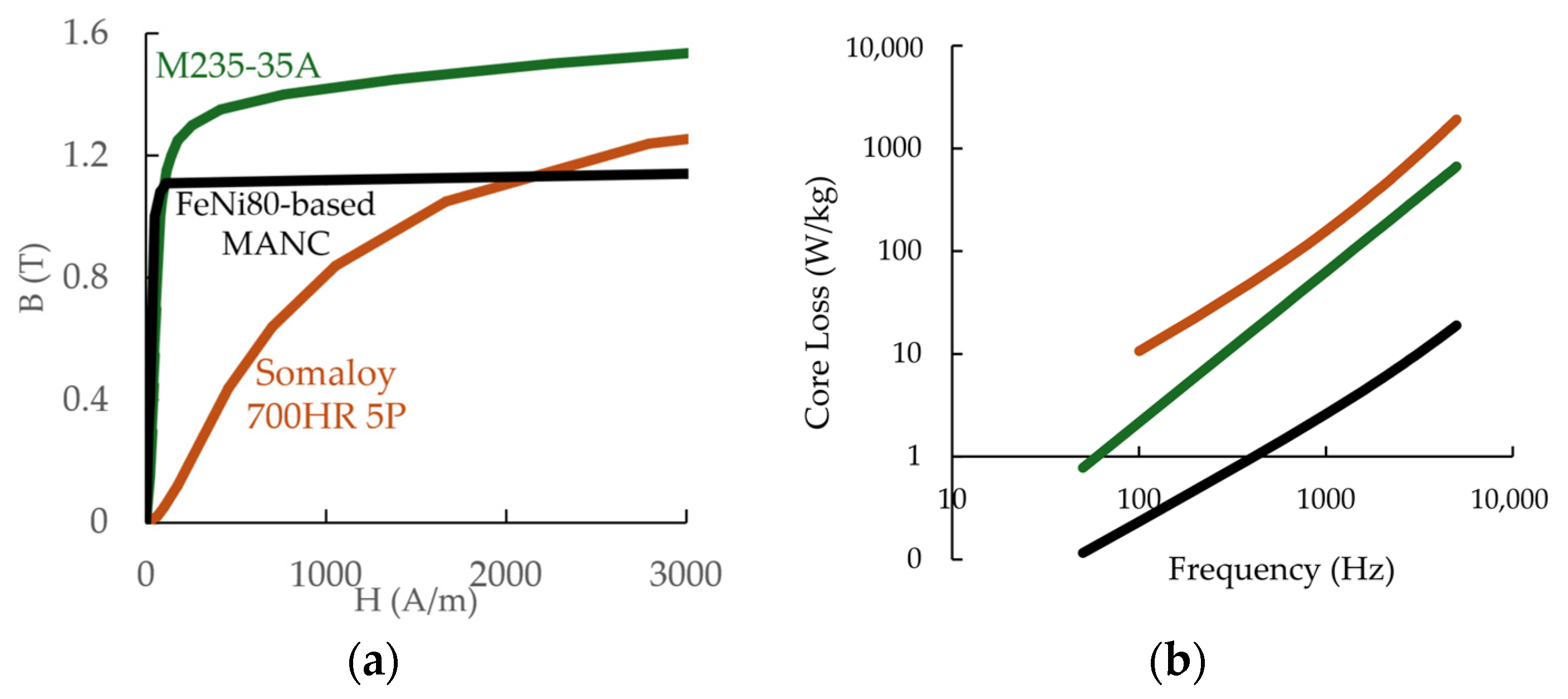
9] demonstrates feasibility for the use of this topology with MANCs, employing manufacturing methods that include toroidal core fabrication and impregnation, core cutting with a waterjet, and the assembly of pieces and magnetized permanent magnets (PMs) to both each other and housing components with epoxy adhesive. A comparison of the magnetic properties of the MANC alloy of interest here with other alloys relevant to existing axial motors is given in
Figure 1.
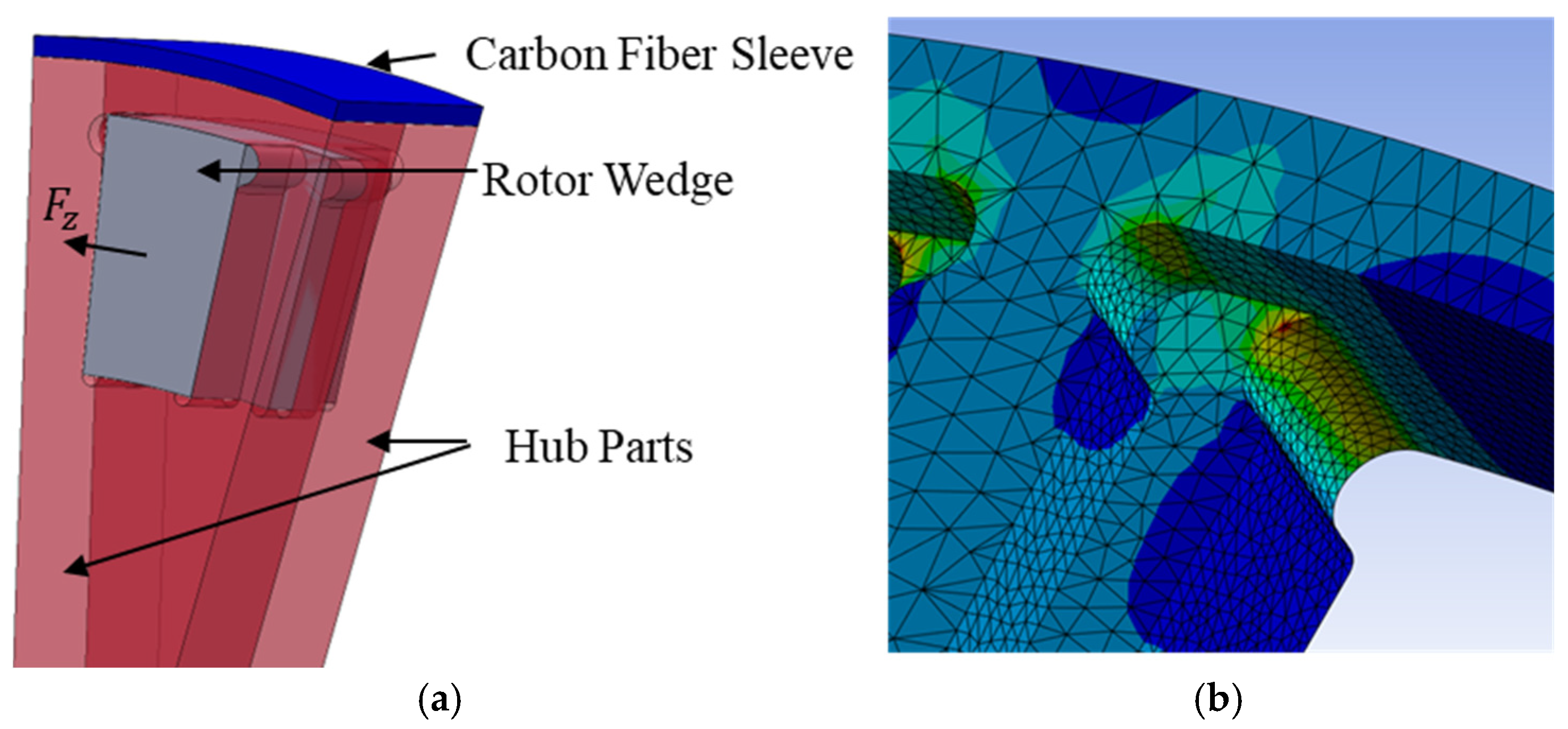
The FSPM motor topology, shown with coils removed in
Figure 2a, is particularly well suited to the use of MANCs because it utilizes a high rate of magnetic switching per mechanical rotation to increase torque. These machines operate by principles similar to switched reluctance machines, where the stator field pulls the rotor toward a position with lower magnetic reluctance. Before this equilibrium position is reached, the stator field changes, continuously exerting electromagnetic torque on the rotor to maintain rotary motion. While switched reluctance machines are typically driven by a square wave, the FSPM topology utilizes a sinusoidal wave.
As shown in
Figure 2, unlike surface PM machines, FSPM motor rotors contain no PMs, and the magnetic flux flowing through the rotor SMM switches direction during the electrical cycle. Switched reluctance machines exhibit a switch in rotor flux direction when a rotor tooth moves from one stator tooth to the next. The flux direction in an FSPM rotor also switches when a rotor tooth passes over a PM embedded in the stator tooth. The torque generated by the magnetic flux between the rotor and stator can be calculated via the Maxwell stress tensor [
12] and by integrating the magnetic flux across the rotor–stator air gap.
Many PM motor topologies, such as surface PM machines, only develop significant eddy current loss in the stator and not in the rotor. However, machines such as switched reluctance machines and FSPM machines develop rotor eddy current (EC) loss due to a change in flux direction as rotor and stator poles pass each other [
13,
14,
15]. This creates a high torque density at the cost of a higher magnetic switching frequency. These topologies benefit from SMMs with lower EC loss because of their elevated magnetic frequency. One example of a well-optimized axial FSPM using grain-oriented silicon steel had SMM losses approximately double that of the copper losses while operating at only 600 RPM [
16], bringing down its electromagnetic efficiency to a maximum of 91%. This example illustrates how even high-grade silicon steels struggle with core losses when one attempts to use them in high-torque-density, high-frequency topologies like FSPM motors.
This present work seeks to determine whether this motor technology can be used to achieve competitive power density and efficiency while using rare earth-free PMs. We alter the motor topology discussed in ref. [
9] and conduct an optimization, by means of a genetic algorithm, in search of specific power improvement. Alteration to the magnetic flux path results in a substantial change in the rotor failure mechanism, motivating us to revisit the mechanical failure problem addressed in ref. [
17] for a different rotor construction. The stator uses rare earth-free ferrite PMs and thereby seeks to demonstrate competitive specific power without the use of expensive and sensitive rare earth materials. We select the use case of an EV traction motor for this motor optimization, where a rated power of approximately 200 kW is desired. This allows us to determine whether MANC motors are capable of challenging state-of-the-art motors with respect to efficiency and specific power.
3. Motor Optimization
We select a population-based optimization strategy, in part using an open-source MATLAB code published by Sudhoff [
21], to explore designs for the motor topology described in
Section 1. To ensure that each motor design receives accurate analysis and provides an accurate fitness value to the genetic algorithm, we model the motor using COMSOL Multiphysics 6.1 and conduct mesh refinement. Each design is generated by the MATLAB code and sent to COMSOL for analysis, which returns the relevant performance parameters. Genetic algorithm-based optimization methods help to avoid local performance maxima but they require many solutions [
22,
23]. This is problematic for a motor topology with a complex electromagnetic solution, as many elements are required to obtain an accurate solution. We therefore employ several strategies to constrain the design space and analysis routine for computational efficiency.
To begin, we limit the allowable number of rotor and stator poles to combinations that are known to provide the least torque ripple. This allows for the analysis routine to solve the magnetic circuit for only one rotor position. As discussed by Simizu [
9], the optimal number of rotor poles (
) for maximum torque density and minimum torque ripple is:
This constrains the number of possible designs to be:
where
is the number of stator pole pairs per phase and
is the number of stator poles. The motor also has sector symmetry with a basis of
, meaning we model a sector with angle
for each design.
As discussed in the introduction, the FSPM motor topology is particularly well suited to MANC properties due to its high-frequency nature. FSPM motors exhibit a change in the direction of air gap flux each time a rotor pole passes a stator pole. Given the high number of stator and rotor poles, this leads to a high rate of magnetic switching per mechanical rotation accompanied by a high torque density. The magnetic frequencies in the stator (
) and rotor (
) for a given mechanical frequency (
) are given by:
The frequencies given by Equations (7) and (8) are used to calculate the SMM loss in the stator and rotor, respectively.
We select pole counts to minimize torque ripple, limiting each motor model to one rotor position. However, this removes the ability to calculate SMM losses with high accuracy. The loss calculation, using the Steinmetz equation [
24], requires the flux density distribution throughout the magnetic cycle. To address this issue, we make a conservative estimate by assuming that every point throughout the geometry is magnetically saturated at some point throughout the magnetic cycle. This calculation will certainly overestimate the SMM losses but an optimized design will make good use of the full SMM volume, where a high percentage of the material reaches near saturation once per magnetic cycle.
SMM losses are typically kept below 300 W/L for air-cooled machines [
25], which leads to a temperature rise of approximately 5 °C/min. However, an EV motor is only expected to deliver the rated power for short periods of time, with longer periods at cruising speed often consuming as little as 10 kW (5% of rated power). At lower power levels, the SMM loss density is lower. We therefore choose 500 W/L as the SMM loss density limit, which leads to a temperature rise of approximately 9 °C/min. While the stator SMM is allowed to reach this loss density, the magnetic frequency in the rotor is far lower, meaning it has a far lower SMM loss. It is therefore safe to assume that the rotor and stator can be passively cooled at this SMM loss limit in a typical passenger EV use case. The Steinmetz equation used to calculate the SMM losses is given by [
24]:
where
represents hysteresis,
represents eddy current, and
represents excess loss, related to anomalous eddy currents from domain wall motion. Also,
is dependent on the material,
is the magnetic frequency,
is the peak magnetic flux density,
is 1, and
and
are 2. Exponents
,
, and
and each
are determined by empirical fit. Importantly,
, where
is the SMM layer thickness and
is the SMM electrical resistivity. Additionally,
= 1 kHz and
= 1.0 T and are the reference frequency and reference flux density, respectively.
Table 2 gives the parameters used in the optimization. These correspond to published values [
9] for the (Fe
70Ni
30)
80B
14Nb
4Si
2 MANC whose mechanical properties are reported [
26] and used [
17] in previous work. The Steinmetz parameters of
Table 2 are those from MANC cores that have not been impregnated. Impregnation does alter the magnetic hysteresis loss. However, the magnetic properties of impregnated cores change with tape-wound core (TWC) geometry. We estimate these losses in the model and discuss them in
Section 4.
Winding loss density, however, is typically larger for highly specific power designs. Because of the easy access to the concentrated windings on the stator poles, we design for liquid cooling of stator coils to remove excess heat. A commonly accepted range of current density for liquid-cooled copper windings is 10–30 A/mm2. In the optimization, we constrain the peak current density to 10–20 A/mm2 to leave extra potential cooling capacity for stator SMM losses during extended periods of high load, such as hill climbing, during which the SMM loss may contribute to heating the windings. We calculate the skin depth for each design to ensure it is sufficiently large that DC winding losses are accurate. We use a fixed coil fill factor of 50% for all designs, as this was found to be feasible in early prototypes.
The most accurate solution for the magnetic flux distribution throughout the motor is a nonlinear model that considers magnetic saturation. Given the computational expense associated with this modeling approach, we choose to model each motor design assuming a linear magnetic response, which provides much faster solutions and is a good approximation for the magnetic material being used. To account for magnetic saturation, we calculate the percentage of the volume that reaches near saturation at every relevant sector throughout the rotor geometry. These sectors are elements of the flux path, including the rotor wedge, stator pole, and stator back iron. We then place a limit on the percentage of each sector that is allowed to reach this near-saturation value. This limit is defined as 10% for this optimization. If a motor design has a percentage of volume exceeding this limit, that design fails the saturation criterion. All variable constraints for the optimization are summarized in
Table 3.
Table 3 also includes constraints placed on the independent variables that define the motor geometry. As mentioned above, this optimization seeks to find the highest specific power for a machine using ferrite PMs with no rare earth materials. We assume that the ferrite PMs have a remanence magnetization,
, of 0.4 T and a recoil permeability of 1.05. The fixed variables in the optimization are the SMM and PM materials, copper fill factor (50%), rotor hub outer band thickness (5 mm), and fiber sleeve thickness (2 mm).
For each motor design, the maximum allowable rotational speed is calculated individually for the loss limitation and the mechanical limitation. We select the smaller of these two speeds as the motor-rated speed, and the motor is labeled by the limiting factor. We simplify the solution by assuming that the inverter can supply the required voltage at this speed and do not consider a flux weakening zone. The assumption of acceptable back EMF is checked in the validation of competitive designs after the optimization. This simplification of having no flux weakening zone enables a larger number of solutions.
Table 3.
Parameter constraints for motor optimization.
Table 3.
Parameter constraints for motor optimization.
| # | Parameter | Minimum Value | Maximum Value | Description |
|---|
| | | | | SMM loss density |
| | | | | Normalized centripetal force |
| | | 160 kW | 240 kW | Motor power output |
| | | | 1.25 T | Acceptable local flux density |
| | | 0.0 | 0.15 | |
| 1 | | 0.3 | 0.5 | Fraction of rotor circumference consumed by rotor teeth |
| 2 | | 0.4 | 0.6 | Fraction of stator height used for coil slot |
| 3 | | 0.2 | 0.4 | Fraction of stator circumference used for PMs |
| 4 | | 0.2 | 0.5 | Fraction of stator circumference used for coil slot |
| 5 | | 6 | 8 | Stator pole pairs per phase (integer) |
| 6 | | 175 mm | 275 mm | Inner radius |
| 7 | | 20 mm | 40 mm | Outer minus inner radius |
| 8 | | 1 mm | 3 mm | Rotor–stator gap length |
| 9 | | 4 mm | 6 mm | Rotor tip height |
| 10 | | 4 mm | 8 mm | Rotor wedge protrusion height |
| 11 | | 20 mm | 35 mm | Stator overall height |
| 12 | | | | Current density |
The model calculates torque by integrating the flux density components through the midpoint of the air gap, given by:
where
and
are the horizontal and vertical flux density components, respectively. In the 2D model shown in
Figure 1, this is a line integral. In a 3D model, this becomes a surface integral of the annulus at the midpoint between the rotor and stator.
The optimization routine proceeds according to the following process. When the first population of designs is generated within the constraints of
Table 3, each is assessed according to the objective function, where the design is generated in COMSOL and analyzed to calculate single-point torque, power, loss, and mass. In addition to the parameter constraints listed above, the assumptions for this analysis are that we conduct a static model of a single operating point, assume linear magnetic response with no more than 15% of the SMM exceeding the saturation flux density, and assume that all of the SMM reaches saturation for purposes of iron loss calculation. The objective function is an equal weighting of the results of electromagnetic efficiency and specific power. The designs that pass the constraints of
Table 3 are included in the genome of the next generation. This is repeated for multiple generations. After the prescribed number of generations has evolved, the results are reported and the selected designs are analyzed in more detail. Thus, the population-based optimization method in general is applicable to all types of motors but the fitness function’s electromagnetic model is specific to the axial FSPM topology.
Given the assumptions and the process, we conduct a dual-objective genetic algorithm optimization of the direct FSPM motor searching for designs that maximize electromagnetic efficiency and specific power. Electromagnetic efficiency only includes SMM and winding losses and excludes bearing, windage, and inverter loss. The specific power calculation includes the electromagnetically active mass and the estimated mass of the housing and rotor hub and sleeve. Housing, hub, and sleeve mass calculations are approximate and based on motor dimensions. The housing mass includes the estimated mass needed for liquid cooling channels contacting the stator coils but excludes the mass of the coolant, radiator, and pump. Also excluded is the mass of the rotor shaft and geartrain. We therefore find the dry mass of the motor alone to provide a direct specific power comparison with other high-performance EV motors such as the Tesla Model 3 motor. This radial flux Internal PM Synchronous Reluctance Motor is used in the single-motor Model 3 and as one of the motors in the dual-motor Model 3 and tri-motor Model S. It has a rated power of 208 kW [
27] and reportedly has a dry mass of 45 kg [
28], giving it a specific power of 4.6 kW/kg. The Model 3 design uses rare earth PMs.
4. Results
Constraining the solution space as described in
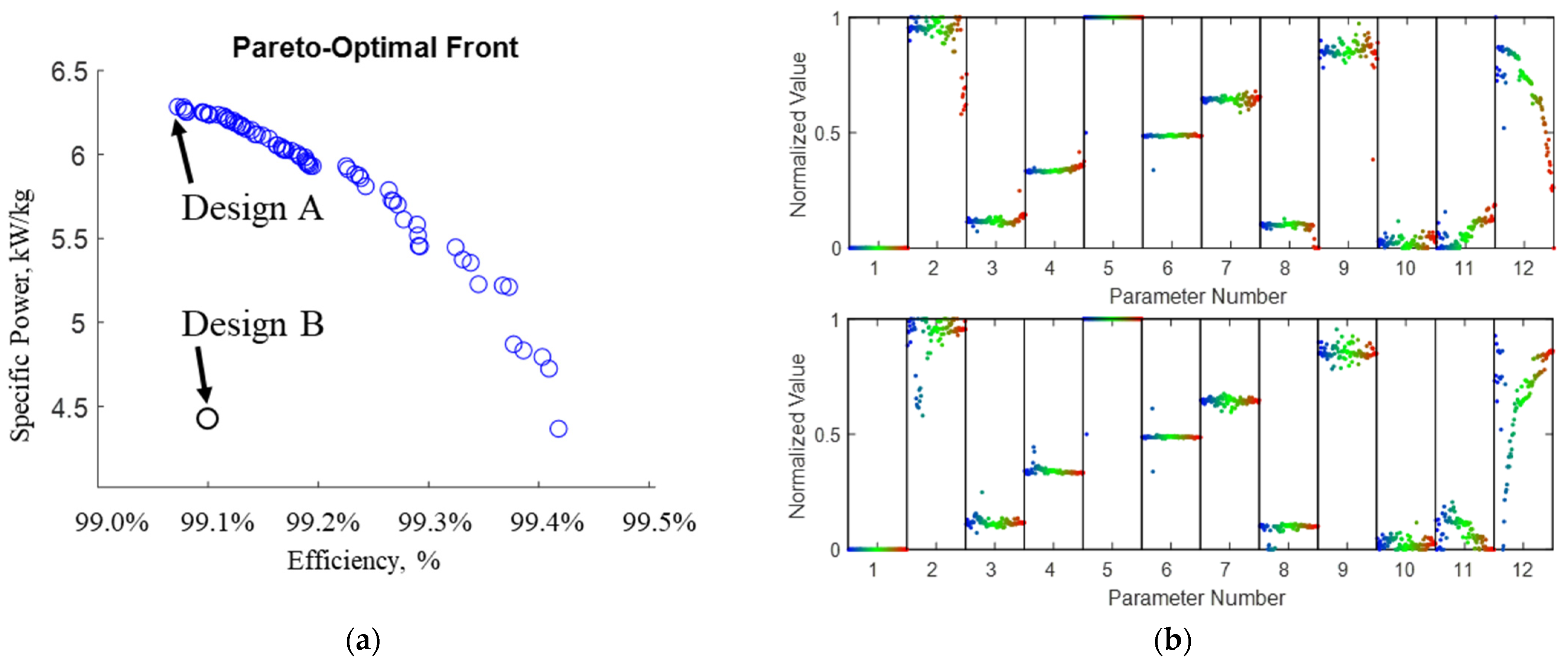
Section 3 allows an optimization of 200 individuals across 200 generations. Each optimal design is limited by stress. We then find the Pareto-optimal front shown in
Figure 4a in terms of specific power versus electromagnetic efficiency. Each point in
Figure 4a represents a different design, and the blue dots indicate designs with 8 stator pole pairs per phase (48 total poles). Design B is from designs with 7 stator pole pairs per phase (42 total poles). More details on Designs A and B are provided in
Section 5. The dependence of efficiency and specific power on each normalized parameter from
Table 3 is shown in
Figure 4b. Here, a normalized parameter of 0 represents that the parameter is equal to the lower bound placed on it in
Table 3. A normalized parameter of 1 indicates a parameter equal to the upper bound placed on it in
Table 3. Parameter 12,
, is especially of note, showing that increasing current density results in increasing specific power and decreasing efficiency. Here, the blue dots in Parameter 12 represent low current density, slightly above 10 Amp/mm
2, and the red dots represent higher values nearer to the upper bound of 20 Amp/mm
2.
We now conduct another FEA analysis of Designs A and B at several rotor positions throughout the electrical cycle, which enables the calculation of back EMF and torque ripple. The average torque value is used to calculate power
in
Table 4. We find that each stator coil has a back EMF waveform that is nearly sinusoidal, with a peak voltage in Design A of approximately 350 V. Torque ripple is less than 8% of the average torque (248 Nm), which can be considered acceptable. Also included in the validation FEA is a calculation of the working point of the PM. A conservative value for the minimum working point is 50% of the
of the PM, though as low as 25% may be acceptable depending on the operating temperature. Design A exhibits PM working points between 30–70% of
throughout the electrical cycle, which can be considered acceptable.
A validation FEA model for the mechanical limitation of Design A reveals hub yielding at
170 Hz, higher than that calculated by Equation (4) and given in
Table 4. This is expected, as the
used in the optimization is 80% of the average from the rotor geometries tested with FEA.
5. Discussion
As
Figure 4a shows, all the designs with the highest fitness values (electromagnetic efficiency and specific power) have only slight variations in efficiency. This is largely due to the constraints placed on SMM and winding loss. The constraints placed on SMM loss are so stringent that as the algorithm finds designs that push against the limits of SMM loss to maximize specific power, the power loss remains low. The SMM loss modeling is conservative on the basis that all material is saturated, but the Steinmetz parameters of
Table 2 are those of non-impregnated TWCs and the model does not include losses associated with the harmonic content of an inverter waveform. From internal testing, we estimate that at the stator frequency of 7.1 kHz, the SMM losses when considering stresses associated with TWC impregnation would increase by a factor of at maximum ~2.6, bringing SMM losses from ~400 W to ~1.1 kW. This estimate reduces the efficiency by ~0.3% and maintains a SMM loss below the constraint of 500 W/L. Further process optimization may be employed to minimize these effects. This phenomenon is not exhaustively explored in the literature but the stresses are explored in ref. [
17] and the impact on properties is demonstrated for the alloy in question in ref. [
5].
Table 4 shows performance highlights and the values for each free parameter from Designs A and B. We highlight Design A because it has the highest specific power without significantly reduced efficiency when compared with other designs. This is the design in the top left corner of the Pareto-optimal front in
Figure 4a. The lower pole count
7 of Design B reduces its manufacturing complexity but it does not exist on the Pareto-optimal front, as all optimal designs have
8.
The high electrical frequency in optimized motor designs is due to a high pole count, which points to drawbacks that can be addressed by future technological developments. The high pole count makes good use of the low SMM losses at high frequency to improve torque density. However, the high pole count increases back-EMF as well as inverter, winding, and iron losses. The FEA that models the motor over a full electrical cycle provides the result of 350 V peak back-EMF, which is achievable with existing inverter and coil insulation technologies, given that coils are wired in parallel. The high electrical frequency of 7.1 kHz, however, presents a major challenge to inverter design and loss, motivating the use of next-generation motor drives. Additionally, having many small poles and a large rotor diameter increases manufacturing complexity.
This work shows that MANCs can utilize the axial FSWPM motor topology to achieve a competitive specific power without the use of rare earth PMs. To compare with a relevant EV motor used in industry today, the example of a Tesla Model 3 motor is used. Considering the dry mass of the motor and housing, this IPMSM has a specific power of 4.6 kW/kg using rare earth PMs. The specific power of Designs A and B are ~33% higher than and ~11% lower than this value, respectively, in the absence of rare earth PMs. Assuming passive cooling for SMM losses, these metrics are met while achieving an electromagnetic efficiency of 99% while requiring no liquid cooling for SMM laminates. Put simply, this remarkably high electromagnetic efficiency is achieved by the low iron losses of MANC alloys and by allotting a large enough cross-sectional conductor area to minimize conductor losses.
As discussed in
Section 2, we use a close-fit hub and sleeve design that remains constant for all rotor geometries modeled to assess the mechanical limit. Future work should address sleeve design optimization, as only one sleeve design is studied here. Additionally, dynamic stresses and resonance concerns are not addressed in
Section 2 but should be considered. Optimal hub and housing design and material selection are other important areas, as these components are important for bearing rotational load and containment in the event of rotor failure. Finally, transient analysis, efficiency mapping, nonlinear analysis, and prototype tests are required to further validate design feasibility and performance.
The innovative aspects of this work include a computationally efficient estimation for the mechanical limit of axial flux rotors of this construction and a design study of an axial flux-switching design with MANC SMMs and ferrite PMs, which demonstrates competitive specific power and efficiency for EV traction applications in the absence of rare earth materials. Future work should also investigate design methods to meet automotive powertrain needs and maintain high efficiency while reducing frequency and manufacturing complexity and prototyping larger MANC motor components, as the large diameter and large number of small poles are important aspects of future manufacturing process development. Nonetheless, this work demonstrates that with sufficient advancements in motor drive technology and manufacturing processes, MANCs can be utilized to dramatically increase EV drivetrain efficiency while using rare earth-free PMs and maintaining a competitive specific power.


