Article

Research on the Oil Cooling Structure Design Method of Permanent Magnet Synchronous Motors for Electric Vehicles

1
School of Electronic Engineering and Intelligent Manufacturing, Anqing Normal University, Anqing 246133, China
2
Anhui Tongfeng Electronics Co., Ltd., Tongling 244000, China
*
Author to whom correspondence should be addressed.
Energies 2025, 18(12), 3134; https://doi.org/10.3390/en18123134 (registering DOI)
Submission received: 18 May 2025 / Revised: 8 June 2025 / Accepted: 13 June 2025 / Published: 14 June 2025
(This article belongs to the Special Issue Advances in Permanent Magnet Motor and Motor Control)

Abstract

:
Permanent magnet synchronous motors for electric vehicles (EVs) prioritize high power density and lightweight design, leading to elevated thermal flux density. Consequently, cooling methods and heat conduction in stator windings become critical. This paper proposes a compound cooling structure combining direct oil spray cooling on stator windings and housing oil channel cooling (referred to as the winding–housing composite oil cooling system) for permanent synchronous motors in EVs. A systematic design methodology for oil jet nozzles and housing oil channels is investigated, determining the average convective heat transfer coefficient on end-winding surfaces and the heat dissipation factor of the oil channels. Finite element analysis (FEA) was employed to simulate the thermal field of a 48-slot 8-pole oil-cooled motor, with further analysis on the effects of oil temperature and flow rate on motor temperature. Based on these findings, an optimized oil-cooled structure is proposed, demonstrating enhanced thermal management efficiency. The results provide valuable references for the design of cooling systems in oil-cooled motors for EV applications.

1. Introduction

With the increasingly stringent demands for motor power density in new energy vehicles, traditional air- and water-cooling technologies are approaching their thermal limits. Against this backdrop, oil cooling technology has become a research hotspot due to its high dielectric constant, non-magnetic properties, high insulation, and strong convective heat transfer capabilities. The EU Motor Efficiency Enhancement Plan explicitly states that all motors with output power between 75 and 200 kW must meet IE4 or higher international efficiency standards starting from July 2023. This has directly accelerated the engineering application of oil cooling technology. Reference [1] optimized the thermal performance of an aerospace oil-cooled motor by analyzing its internal oil flow patterns through CFD modeling. Reference [2] designed an oil-cooling-centric thermal management structure to address the performance limitations caused by heat dissipation challenges in hub motors, establishing a thermal distribution model validated by simulations and experiments. Reference [3] investigated the thermal performance of oil-cooled permanent magnet synchronous motors (PMSMs), analyzing their cooling efficiency under different oil parameters.
Oil-cooled motors are primarily categorized into direct and indirect cooling based on the contact form between the cooling oil and the stator yoke. Indirect oil cooling, implemented via housing oil channels [4], enables non-contact heat dissipation with advantages such as good sealing and simplified maintenance. However, excessive thermal resistance layers limit heat transfer efficiency. Direct oil cooling, achieved through immersion or spray methods [5], allows direct contact between the cooling oil and heat-generating components. For example, Reference [6] studied the thermal and economic characteristics of direct oil cooling in electric traction motors, considering variations in cooling oils and drive duty cycles. Notably, the end windings—the largest heat source in motors—directly impact system reliability through their cooling efficiency. Moreover, spray cooling with different flow rates, velocities, nozzle types (e.g., pressure nozzles), and nozzle quantities exhibits distinct effects on winding temperatures and heat transfer coefficients. Reference [7] concluded that full-cone nozzles offer superior heat dissipation efficiency, while hollow-cone nozzles provide better temperature uniformity.
In recent years, hybrid cooling solutions leveraging multi-physics synergy have emerged as breakthrough strategies. For instance, Reference [8] proposed a shaft-housing coupled cooling method that reduces motor temperatures by over 20 °C. Spray + immersion combinations have also been adopted to enhance heat dissipation. However, existing research predominantly focuses on single-component optimization, lacking system-level thermal management design:
(1)
The matching mechanism between spray parameters and oil channel structures remains unclear.
(2)
The oil pressure balancing challenge in multiple cooling paths leads to local flow stagnation.
(3)
The impact of hybrid cooling on electromagnetic performance has not yet been quantified.
Reference [9] highlights efforts to integrate spray cooling technology into EV motors, discussing the advancements and challenges of this novel thermal management approach in enhancing the power density of electric traction motors.
Reference [10] studied an indirectly oil-cooled permanent magnet traction motor with a rated power of 100 kW and a rated speed of 4000 r/min. Heat dissipation is achieved through oil channels designed on the motor housing. Cooling oil at 25 °C removes 5 kW of heat, demonstrating excellent cooling performance. Reference [11] investigated the thermal structure and temperature field of an indirectly oil-cooled switched reluctance starter/generator. The study first calculated motor losses using finite element software and designed an indirect oil-cooling structure characterized by a large heat dissipation area, low internal resistance, and superior sealing. Cooling oil extracts heat via convective heat transfer within an axial helical structure.
Direct oil-cooled motors differ from indirect ones in cooling structure and heat transfer processes. Direct cooling involves oil directly contacting heat sources (e.g., windings) to remove heat through convection. This method suits motors operating under high thermal loads and harsh environments. However, the complex internal oil flow patterns in direct cooling systems make accurate temperature field calculations challenging, necessitating advanced modeling for theoretical and practical guidance. Reference [12] explored a direct oil-cooling system for EV motors, combining spray cooling and circulatory oil cooling. Oil indirectly extracts heat via housing channels while being directly sprayed onto windings and stator/rotor ends, significantly enhancing cooling for end windings and permanent magnets.
Reference [13] improved the cooling and lubrication of a direct oil-cooled motor by designing oil channels within the hollow shaft to cool winding ends, bearings, and gears. Orthogonal matrix analysis optimized key cooling parameters, resulting in a system outperforming traditional designs. Reference [14] describes Tesla’s compound hollow shaft sleeve with dual annular chambers. Oil flows inward, reverses direction at a sealed wall, and exits through an outer chamber in contact with the rotor, providing supplemental cooling. Reference [15] details Tesla’s hybrid system combining shaft and housing cooling: oil first cools the rotor via centrifugal pumping, then flows to the housing for stator cooling and ambient heat exchange.
Reference [16] implemented in-slot oil cooling by designing axial oil channels adjacent to stator windings. Heat transfers from windings to channels via slot contacts, but increased airgap length (to prevent oil leakage into the rotor) reduces magnetic loading and raises thermal stress. Slot cooling also lowers the slot fill ratio, reducing efficiency. Despite superior cooling, its high cost and design complexity limit applications to niche markets. Reference [17] utilized spray ring cooling, where automatic transmission fluid (ATF) is sprayed onto winding ends via nozzles, achieving uniform cooling across internal and external surfaces. Reference [18] positioned spray nozzles near stator windings, relying on gravity for oil distribution. While spray cooling offers 2.5–5× higher heat removal than air cooling, uneven oil distribution due to gravity and rotor rotation creates temperature gradients, necessitating hybrid approaches (e.g., spray + housing or spray + immersion).
Conclusion: Balancing structural feasibility, manufacturability, cost, and cooling efficiency, this study adopts a combined cooling scheme of direct stator winding spray + housing oil channels. As shown in Figure 1, cooling oil enters through the inlet, sprays onto stator end windings via dual nozzles, flows through housing channels to cool the stator core, and collects in the bottom reservoir before exiting through the outlet. This structure ensures sufficient cooling for the stator windings while simultaneously enabling stator core cooling through the cooling oil. By designing appropriate oil reservoirs and strategically positioned oil outlets, the stator core can be fully immersed in the cooling oil, thereby achieving enhanced cooling performance.

2. Oil Cooling Structure Design for PMSMs-EVs

2.1. Design of Oil Jet Nozzles

The prototype stator windings adopt direct spray cooling, with two oil jet nozzles positioned above each end of the stator windings. The nozzle orifice size and placement directly determine the oil film thickness on the end windings, critically influencing their cooling effectiveness. Given the complexity of the end-winding oil spray paths, finite element analysis (FEA) and multivariate nonlinear fitting theory were employed to comprehensively analyze the impact of nozzle orifice size and positioning on the thermal dissipation performance of the motor’s end windings.
Assuming all heat losses from the end windings are removed by the cooling oil, Newton’s law of cooling gives the following:
P c u _ e n d = h A e n d w ( T max T f ) ,
where P c u _ e n d is the copper loss of the end windings; h and Aendw are the convective heat transfer coefficient and convective heat transfer area of the end windings, respectively; Tmax and Tf are the maximum temperature on the end windings and the cooling oil temperature, respectively.
From Equation (1), the maximum temperature estimation formula for the motor’s end windings can be derived as follows:
T max = P c u _ e n d h A e n d w + T f = P c u _ e n d γ e n d + T f ,
where γ e n d is the heat dissipation factor of the end windings, defined as γ e n d = hAendw.
As indicated by Equation (2), under constant end-winding losses, the maximum temperature rise of the motor’s end windings depends on the heat dissipation factor γ e n d . A higher γ e n d signifies superior cooling performance, while a lower value indicates inferior thermal management.
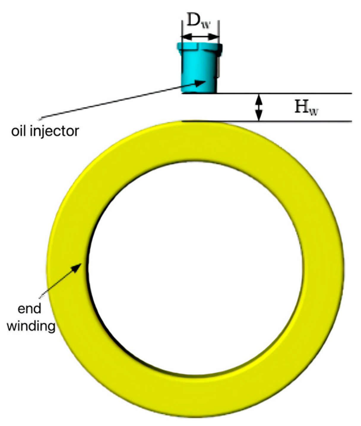
Figure 2 shows the simulation model of the oil jet nozzle and end windings, where the nozzle diameter is denoted as Dw, and the height of the end windings is Hw. The simulation parameters include an inlet oil temperature of 90 °C, an inlet flow rate of 5 L/min (automatic transmission fluid, thermal conductivity: 0.2 W/m·°C, specific heat capacity: 1963 J/(kg·°C), density: 846 kg/m3, dynamic viscosity: 0.0066 Pa·s), and copper losses of 474.7 W per end winding. A 3D finite element simulation was conducted to analyze the influence of nozzle diameter Dw and end-winding height Hw on the average convective heat transfer coefficient (haverage) of the end-winding surfaces. Since the surface area of the end windings is fixed, a higher haverage directly increases the heat dissipation factor ( γ e n d ), thereby improving cooling performance.
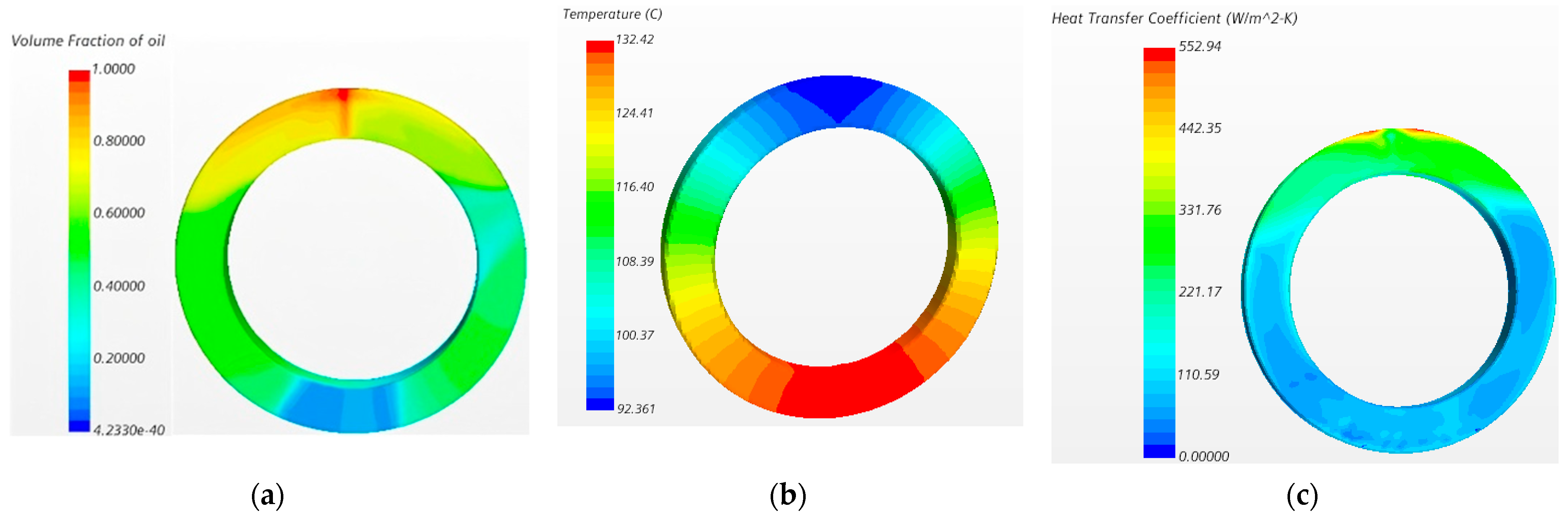
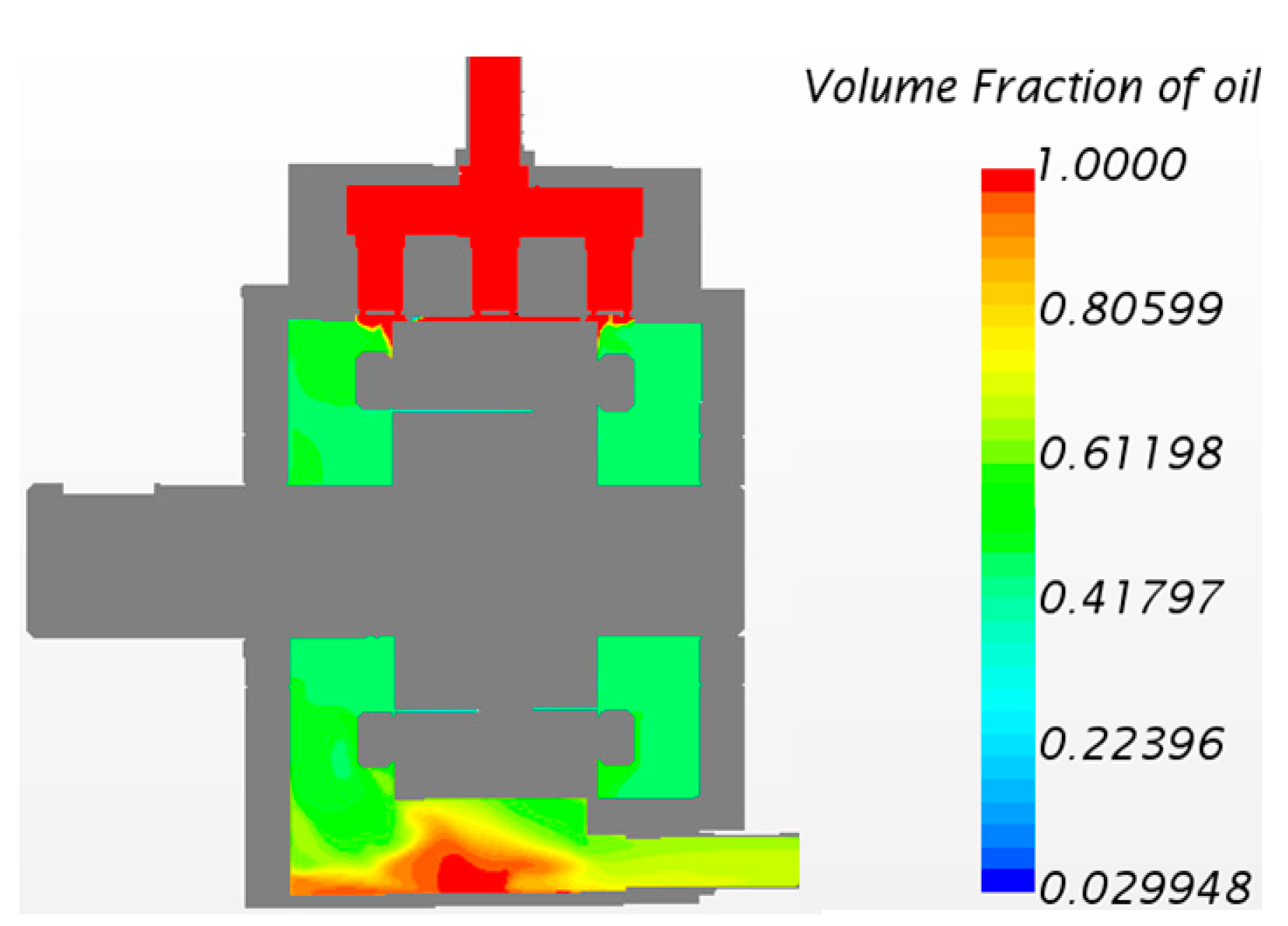
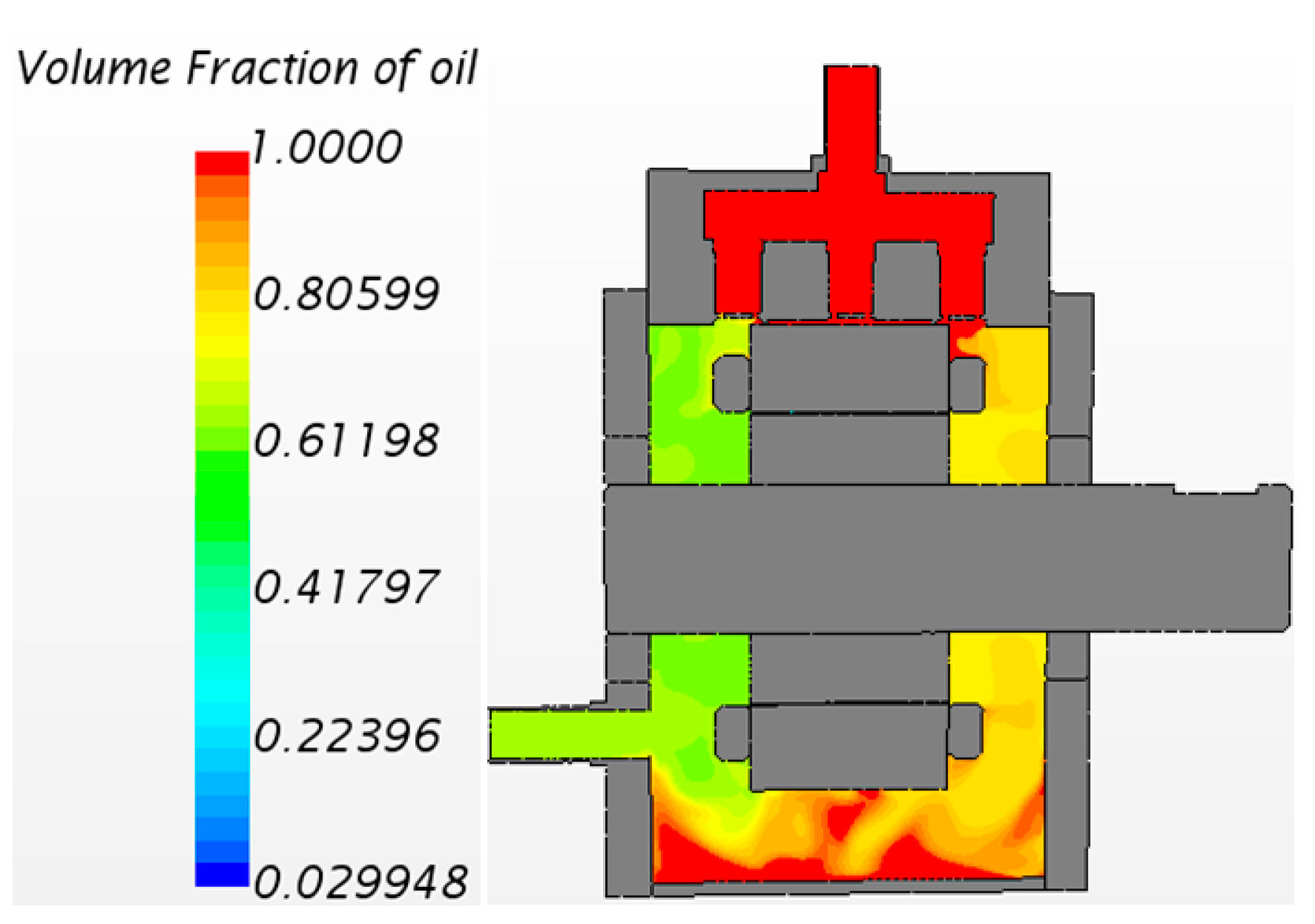
Figure 3 shows the temperature rise simulation results of the end windings with an oil jet nozzle orifice diameter of 1 mm and a vertical position height of 16 mm. In the simulation: value = 1 indicates the corresponding region is fully occupied by cooling oil; value = 0 indicates the region is entirely filled with air. The results reveal that directly below the nozzle, the end windings exhibit the highest concentration of cooling oil, leading to the maximum convective heat transfer coefficient and the lowest temperature of 92.4 °C. Under gravity, the cooling oil flows along the end surfaces of the windings. However, at the bottommost section of the end windings, the oil coverage diminishes significantly, resulting in the highest localized temperature of 132.4 °C.
Using the same analytical method, by varying two parameters—the nozzle orifice diameter and vertical position height—we obtained 49 distinct configurations of the average convective heat transfer coefficient (haverage (W/m2/K)) for the end-winding surfaces, as detailed in Table 1.
Using multivariate nonlinear regression theory, the simulation data from Table 1 were fitted to derive the nonlinear relationship between the convective heat transfer coefficient (haverage) and the nozzle diameter (Dw) and vertical position height (Hw). The analytical procedure is as follows [19]:
Establish the regression function
Y ^ = f ( X i , b i , b 0 ) ,
where Y ^ is the estimated value of the dependent variable Y; Xi are the independent variables; b0 and bi represent the constant term and regression coefficients, respectively.
Residual calculation
e k = y k y ^ k ( k = 1 , 2 , 3 n ) ,
where yk and y ^ k represent the observed value and calculated value of the dependent variable, respectively; ek denotes the deviation between the observed and calculated values; k indicates the observation index.
The objective function of regression analysis:
k = 1 n e k 2 = k = 1 n ( y k y ^ k ) 2 min ,
Based on Equations (3)–(5) and the data from Table 1, the expression for the average convective heat transfer coefficient (haverage) of the end-winding surfaces was derived through regression fitting.
h a v e r a g e = 168.6 12.6 D w 3.253 H w + 0.6896 D w 2 0.2149 H w D w + 0.2858 H w 2 0.01196 D w 3 + 0.00204 D w 2 H w + 0.003833   D w H w 2 0.006227 H w 3 ,
This formula serves as a critical design basis for selecting the nozzle diameter and vertical positioning height in stator end-winding spray cooling systems, enabling rapid optimization of oil-jet nozzle configurations.
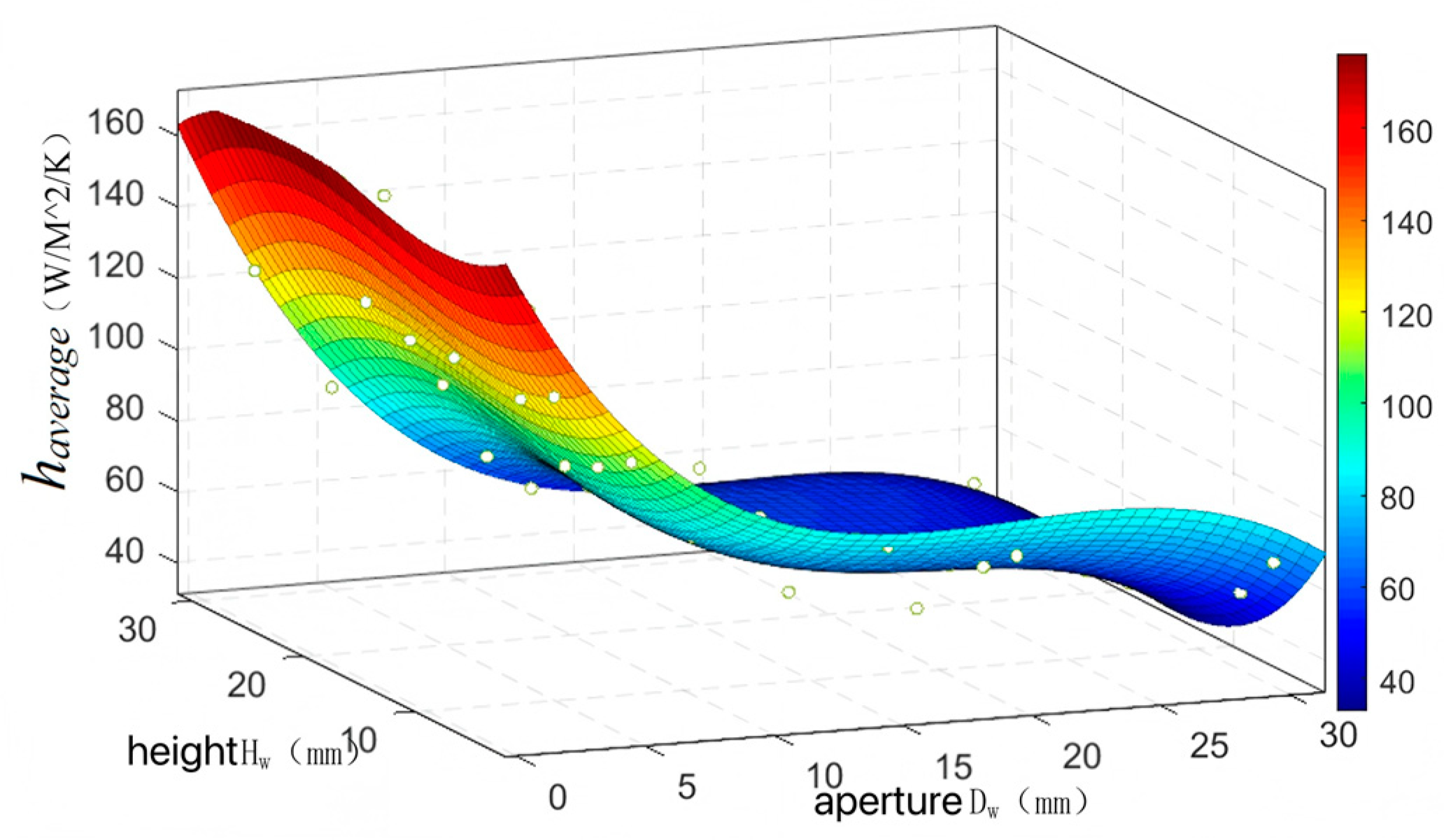
As calculated from Equation (6), Figure 4 illustrates the relationship between the average convective heat transfer coefficient haverage of the end-winding surfaces and the nozzle diameter Dw and positioning height Hw. The results demonstrate that haverage decreases with increasing nozzle diameter, while the positioning height exhibits a nonlinear correlation with the heat transfer coefficient. Design optimization requires a comprehensive consideration of factors including pump power, spatial constraints, cost, and manufacturing feasibility.
Based on Equation (6), the heat dissipation factor of the end windings is obtained as follows:
γ e n d = h a v e r a g e A e n d w = π h a v e r a g e 4 ( D t s 2 D i s 2 ) + l e n d w π h a v e r a g e ( D t s + D i s ) ,
where lendw is the length of the end windings, Dts and Dis denote the tooth root diameter and stator inner diameter of the motor, respectively.

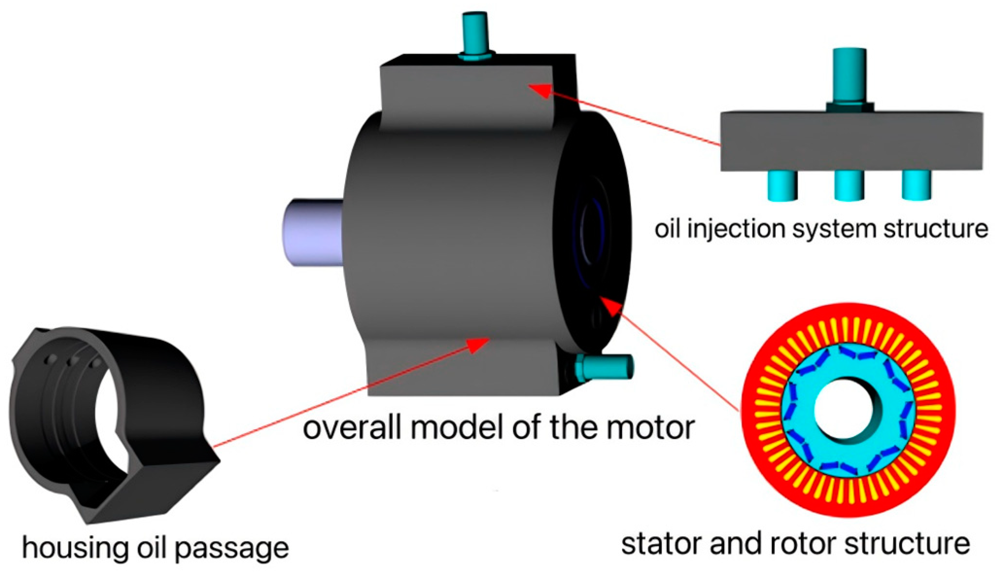
2.2. Design of Housing Oil Channels

Given the manufacturing challenges and poor feasibility of axial helical oil grooves on the inner wall of the motor housing, as well as the adverse impact of stator yoke oil channels on the magnetic circuit, this chapter adopts a circular groove structure on the housing inner wall. The width and depth of the housing oil channels critically determine the thermal dissipation performance of the stator core, while also requiring careful consideration of the housing’s mechanical structural strength.
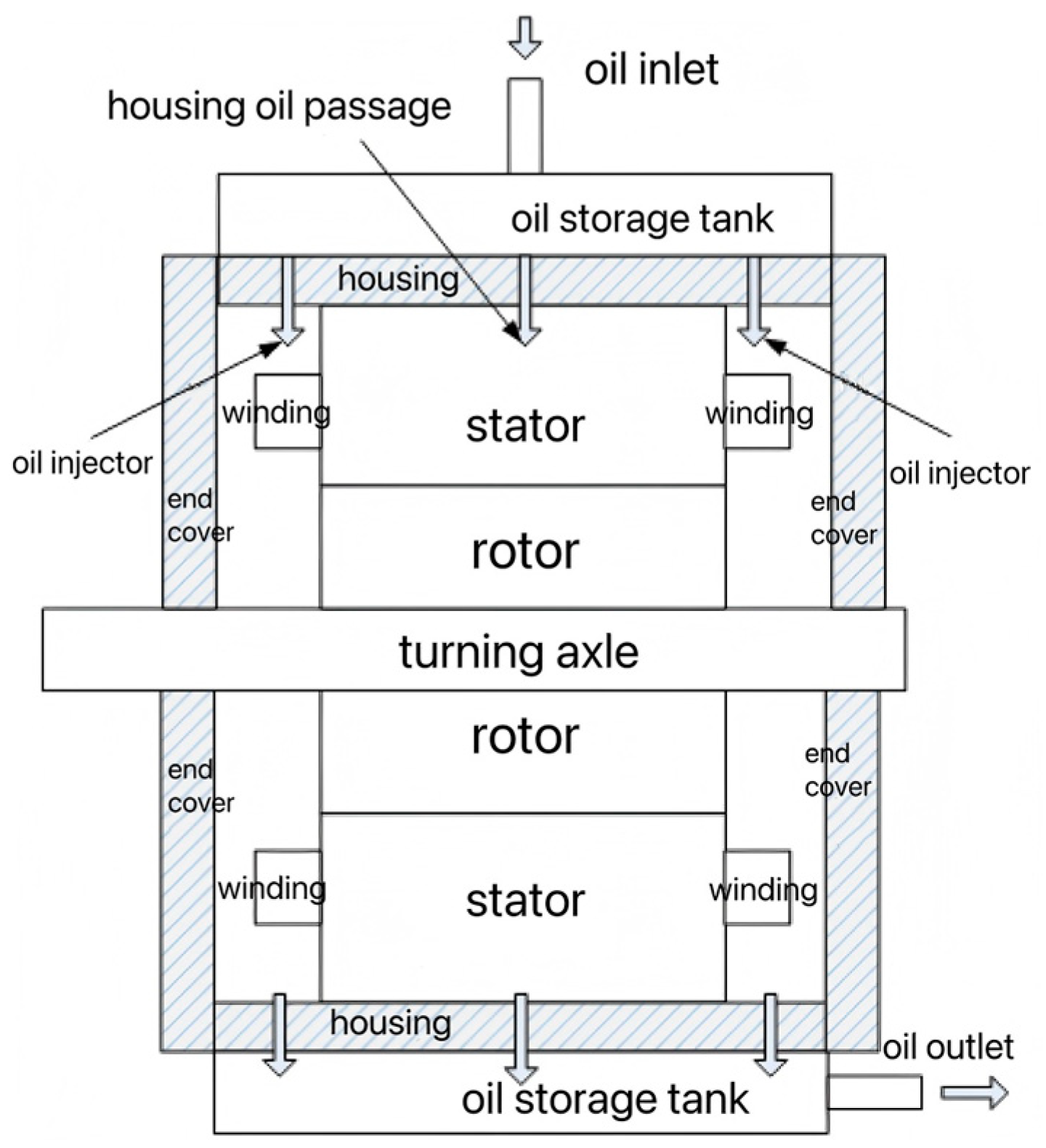
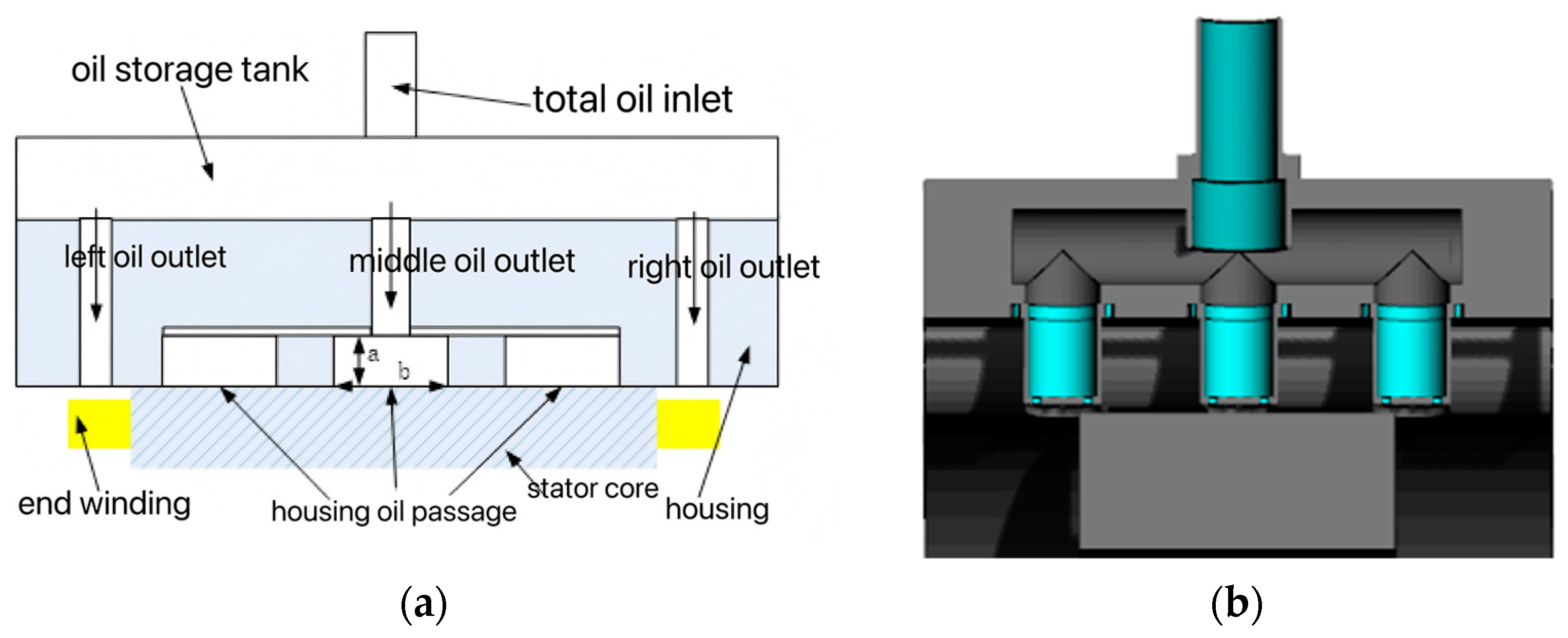
As illustrated in Figure 5, each oil channel operates independently. Cooling oil flows from the main inlet into the top oil reservoir, then distributes through intermediate ports to the housing oil channels, and finally collects in the bottom oil reservoir. Within the channels, the oil flow exhibits three distinct regimes, and the convective heat transfer coefficient under each regime is determined by the Nusselt number (Nu), calculated as follows [20]:
N u = 3.66 , R e 2200.0 0.012 ( R e 0.87 280 ) P r 0.4 [ 1 + ( d / l ) 2 / 3 ] ( p r f p r w ) 0.11 , 2200.0 < R e < 10 4 0.023 R e 0.8 P r 0.4 , R e 10 4 ,
where Re and Pr are the Reynolds number and Prandtl number, respectively; d and l represent the hydraulic diameter and length of the housing oil channels, respectively; Prf and Prw represent the Prandtl numbers calculated with the fluid temperature and the wall temperature as the characteristic temperatures, respectively.
Under specified flow rate and pressure design requirements, the head loss within the housing oil channels directly impacts their cooling effectiveness. Since each housing oil channel has no joints or bends, the cooling oil flow experiences only frictional head loss (also termed major head loss) along the straight channel segments. This loss is proportional to the channel length l and inversely proportional to the hydraulic diameter d. The head loss can be calculated using the following formula:
H f = ξ l d V o i l 2 2 g ,
In the equation, ξ represents the frictional head loss coefficient, Voil is the velocity of the cooling oil within the channel, and g denotes the gravitational acceleration.
Assuming all heat generated by the stator core and slot windings is dissipated by the cooling oil in the housing oil channels, the heat dissipation factor of the housing oil channels ( γ f ) can be derived using the same computational method as Equation (2). A higher γ f indicates a stronger cooling capacity of the oil channels. By optimizing the cross-sectional dimensions of the channels, γ f can be maximized. Additionally, the motor housing must satisfy mechanical structural strength requirements.
Within the housing oil channels, the cooling oil flow velocity (V), hydraulic diameter (d), convective heat transfer coefficient (hfo), and heat transfer area of the oil channels (Afo) can be calculated using Equation (10):
V = Q i N f a b d = 2 a b a + b R e = ρ V d μ f h f o = λ o i l N u d A f o = ( a + b ) N f π D o s ,
In the equation, Qi is the total inlet oil flow rate; μ f and λ o i l are the dynamic viscosity of the fluid and the thermal conductivity of the cooling oil, respectively; a and b are the depth and width dimensions of the housing oil channels, respectively; Dos is the outer diameter of the motor stator; Nf is the number of oil channels in the housing.
Combining Equations (8) and (10), the formula for calculating the heat dissipation factor ( γ f ) of the housing oil channels is derived as follows:
γ f = h f o A f o = 3.66 λ o i l ( a + b ) 2 N f π D o s 2 a b , R e 2200.0 0.012 λ o i l ( a + b ) 2 N f π D o s 2 a b ( R e 0.87 280 ) P r 0.4 [ 1 + ( 4 a b ( a + b ) π D o s ) 2 / 3 ] ( p r f p r w ) 0.11 , 2200.0 < R e < 10 4 0.023 λ o i l ( a + b ) 2 N f π D o s 2 a b R e 0.8 P r 0.4 , R e 10 4 ,
Based on the above, the design methodology for the housing oil channel of PMSMs-EVs can be summarized as follows: Under specified flow rate and pressure requirements, calculate the cooling oil velocity within the housing oil channel, the hydraulic diameter of the channel, and the Reynolds number using Formula (10). Combined with Formulas (8) and (10), determine the flow regime based on the Reynolds number, then compute the corresponding average Nusselt number and convective heat transfer coefficient. Subsequently, calculate the housing heat dissipation factor using Formula (11)—a higher heat dissipation factor indicates better cooling performance. Finally, validate the mechanical structural strength of the motor housing using finite element software to select the optimal dimensional parameters for the housing oil channel.

3. Thermal Field Simulation Analysis of the Electric Motor

3.1. Dimensional Parameters of the Prototype

The prototype analyzed in this study is 48-slot 8-pole PMSMs-EVs. Its technical specifications and primary parameters are summarized in Table 2 and Table 3, respectively.
The prototype employs a combined oil cooling structure featuring direct oil spray on end windings and housing oil channels. The cooling oil inlet flow rate is set to 5 L/min, with an inlet static temperature of 90 °C. Based on Equation (6), the nozzle orifice diameter and positioning height were designed to achieve the maximum average convective heat transfer coefficient on the end-winding surfaces. Substituting relevant parameters into Equations (8)–(10), the calculated Reynolds number (Re), heat dissipation factor ( γ f ) of the housing oil channels, and pressure drop (P) between the inlet and outlet are as follows:
R e = 2 ρ Q i N f ( a + b ) u = 21.4 N f ( a + b ) ,
γ f = 0.066 N f ( a + b ) 2 a b × N u ,
P = ξ 4.84 ( a + b ) × 10 7 a 3 b 3 ,

3.2. Prototype Thermal Field Simulation and Result Analysis

Using Equations (8), (12) and (13), the relationship between the heat dissipation factor ( γ f ) and the parameters Nf, a, and b is established, while satisfying the requirement of Equation (14) (pressure drop between oil channel inlet and outlet ≤ 15 kPa). The mechanical structural strength of the motor housing is then verified via finite element analysis (FEA). The key dimensional parameters of the designed prototype oil cooling structure are listed in Table 4.
To facilitate polyhedral meshing and reduce computational workload, components within the motor were appropriately simplified without compromising the accuracy of temperature distribution. Figure 6 illustrates the simplified 3D model of the motor used for simulation.
Table 5 specifies the material properties of motor components. Table 6 provides the loss distribution values under continuous operation at both rated speed (4775 r/min) and maximum speed (7000 r/min).
The simplified 3D motor model was imported into finite element software to simulate the three-dimensional temperature field distribution under two operating conditions: 4775 r/min @ 100 Nm and 7000 r/min @ 68.2 Nm. For the 4775 r/min @ 100 Nm condition, the cooling oil volume fraction distribution inside the motor is shown in Figure 7, where a value of 1 indicates full oil occupancy, 0 represents pure air, and the distribution reflects the internal oil flow paths. The results reveal a mixed oil–air distribution within the motor. Oil jet nozzles directly spray cooling oil onto both end windings, and under gravity, the oil flows along the end-winding surfaces to the bottom. Simultaneously, cooling oil on the outer surface of the stator core flows through housing oil channels to the motor base, where it collects in the bottom reservoir. However, the oil volume is insufficient to fully submerge the stator core.
Figure 8 shows the temperature contour map of motor components under the 4775 r/min @ 100 Nm condition. The highest temperature on the outer surface of the stator core is located at the motor base. Notably, the maximum winding temperature no longer occurs at the end windings but instead appears in the slot windings at the base. This phenomenon arises because cooling oil flowing through the housing oil channels toward the motor base diminishes in quantity, and the collected oil in the bottom reservoir is insufficient to submerge the stator core.
As shown in Table 7, the highest temperature of the motor does not occur at the end windings but rather at the stator slot windings (4775 rpm @ 100 N·m) or the stator core (7000 rpm @ 68.2 N·m). The overall temperature at 4775 rpm is consistently higher than that at 7000 rpm. This is attributed to the former’s total losses being 332.8 W greater than the latter, with copper losses alone increasing by 807.6 W, leading to elevated temperatures.

4. Analysis of Cooling Oil Temperature and Flow Rate Effects on Thermal Field

Figure 9 shows the simulated temperature variation curves of the motor with oil temperature and flow rate under the 4775 r/min @ 100 Nm operating condition, while maintaining fixed nozzle and housing oil channel dimensions (inlet oil flow rate: 5 L/min). The simulation results reveal the following:
  • The temperatures of key motor components increase with rising inlet oil temperature, and the rate of temperature rise accelerates at higher oil temperatures.
  • Due to direct oil spray on the end windings and rotor end surfaces, the maximum temperature of stator windings shifts from the end windings to the slot windings, while the rotor and permanent magnets exhibit relatively low-temperature rises. This thermal behavior differs from water-cooled housing designs.
  • The critical component temperatures of the prototype decrease with increasing inlet oil flow rate. Below 40 L/min, temperature shows strong flow-rate dependence, though this sensitivity progressively diminishes with higher flow rates. Beyond 40 L/min, further increases in cooling oil flow yield no significant temperature reduction.
Analysis indicates that when the inlet oil flow rate reaches 15 L/min, the cooling oil completely fills the motor interior, as demonstrated by the volume fraction distribution in Figure 10. This operating condition is not recommended in practice because a fully oil-immersed motor substantially increases rotor damping. The resulting effects include significantly reduced operational efficiency and potential mechanical instability risks.
In summary, while increasing the cooling oil flow rate enhances the motor’s cooling effectiveness, it also raises rotor damping and oil pump power consumption, thereby reducing motor efficiency. Consequently, the design must holistically balance cooling performance, motor efficiency, rotor dynamics, and cost to optimally select the cooling oil flow rate. The housing design incorporates only two oil channels, whose relative dimensions are sufficiently small compared to the overall housing size to inherently meet mechanical strength requirements. Therefore, the mechanical stress analysis of the housing was deemed unnecessary and consequently omitted.

5. Improved Design Analysis of the Prototype Oil Cooling Circuit

Analysis of the prototype’s temperature distribution reveals excessive temperatures at the stator windings and the base of the stator core. This issue arises because cooling oil flowing toward the end windings and stator core does not accumulate at the base but instead drains directly into the oil reservoir under gravity. The bottom reservoir collects only a small portion of the oil, with most exiting through the oil outlet. To address this limitation and enhance cooling at the base of the stator core and windings, the oil cooling structure was modified by raising the oil outlet position to align with the central height of the bottom-end windings. This adjustment allows the reservoir to retain more cooling oil, thereby improving thermal management for the base regions.
The oil cooling structure of the PMSMs-EVs was redesigned using the finite element simulation method by elevating the position of the oil outlet. The cooling oil volume fraction distribution contour map inside the improved prototype under the 4775 r/min @ 100 Nm operating condition is shown in Figure 11. It can be observed that the amount of cooling oil collected in the motor’s bottom reservoir has increased compared to the original model. However, the oil volume at the base remains insufficient to fully submerge the stator core and windings at the motor’s bottom.
Figure 12 shows the temperature distribution contour map of motor components for the improved model under the 4775 r/min @ 100 Nm operating condition. A comparison of temperature rise simulation data between the improved and original models is provided in Table 8. The results indicate that, under identical operating conditions and boundary constraints, the improved motor model exhibits significantly lower temperatures across all critical components compared to the original design, with the highest temperature observed at the stator slot windings (137.0 °C). This improvement stems from relocating the oil outlet upward, which increases oil accumulation in the bottom reservoir and enhances cooling efficiency for the stator core, thereby reducing overall temperatures.

6. Conclusions

The design of cooling and thermal management systems is a critical aspect of high-density, high-efficiency PMSMs-EVs. This study focuses on a winding–housing composite oil-cooling structure, with emphasis on the design methodologies for oil jet nozzles and housing oil channels. Leveraging extensive finite element simulation results and applying multivariate nonlinear regression fitting theory, the average convective heat transfer coefficient (haverage) on end-winding surfaces was modeled as a bivariate polynomial function of nozzle orifice diameter and positioning height, revealing their intrinsic relationship. The average convective heat transfer coefficient on the end-winding surface decreases with increasing nozzle orifice diameter, while exhibiting a nonlinear relationship with positional height. Equation (6) provides a basis for rapid optimization of nozzle design parameters. For motors of different sizes, the end-winding cooling factor can be efficiently calculated using Equation (7). Furthermore, we have derived the relationship between the housing oil channel’s cooling factor and its geometric parameters including channel width, depth, and number of channels. Equation (11) enables quick estimation of the housing oil channel cooling factor for variously sized motors. These formulations collectively establish a theoretical framework for rapid thermal assessment of motor cooling structures.
Using a 48-slot 8-pole oil-cooled motor (rated power: 50 kW) as a case study, the temperature distributions under both rated load/rated speed (4775 r/min @ 100 Nm) and maximum speed (7000 r/min @ 68.2 Nm) conditions were analyzed. The influence of oil temperature and flow rate on thermal performance was systematically investigated. An improved oil-cooling structure was proposed, achieving temperature reductions of 10.28% and 9.75% for the stator core and slot windings, respectively, under rated conditions.
The design methodology presented in this study significantly reduces the development costs for oil channel design and optimization while providing a valuable reference for analogous oil-cooled motor architectures. Key contributions include the following:
  • Empirical correlations for haverage and γ f , enabling rapid design iteration.
  • Demonstrated thermal performance enhancements via FEA and parametric studies.
  • Framework applicable to motors across power ranges and cooling configurations.

Author Contributions

Conceptualization, S.C. (Shijun Chen) and C.M.; methodology, S.C. (Shijun Chen) and C.M.; software, S.C. (Shijun Chen) and C.M.; validation, S.C. (Shijun Chen), C.M., X.C., W.Q. and S.C. (Songchao Chu); formal analysis, S.C. (Shijun Chen); investigation, X.C.; resources, S.C. (Songchao Chu); data curation, W.Q.; writing—original draft preparation, S.C. (Shijun Chen), C.M., X.C., W.Q. and S.C. (Songchao Chu); writing—review and editing, S.C. (Shijun Chen) and C.M. All authors have read and agreed to the published version of the manuscript.

Funding

This research was funded by the Anhui Province Key R&D Program High Tech Field Project, grant number 202304a05020084, and 2024 Anhui Province University Science and Engineering Teachers’ Internship Program in Enterprises, grant number. 2024jsqygz47, and the Anhui Province Higher Education Scientific Research Project, grant number 2024AH051084, and the National and Local Joint Engineering Laboratory for High-Efficiency Motors and Control Technologies 2024 Open Fund Project, grant number KFKT202401.

Data Availability Statement

The nature of the data is the motor size parameters; the data can be accessed from the Electrical Machinery Laboratory of Anqing Normal University. The complete data belong to the joint ownership of the Electrical Machinery Laboratory of Anqing Normal University and the enterprise.

Acknowledgments

We would like to thank Anqing Normal University for their support, as well as all the experts and members who provided technical assistance.

Conflicts of Interest

Authors Shijun Chen and Songchao Chu were employed by the company Anhui Tongfeng Electronics Co., Ltd. The remaining authors declare that the research was conducted in the absence of any commercial or financial relationships that could be construed as a potential conflict of interest.

References

  1. Li, M.; Yan, B.; Zhou, Y.; Tian, L. Research and Simulation of Flow Field on Aviation Oil-Cooled Motor. Small Spec. Electr. Mach. 2022, 50, 31–34. [Google Scholar]
  2. Guo, F.; Zhang, C. Oil Cooling Method for Internal Heat Sources in the Outer Rotor Hub Motor of Electric Vehicle and Thermal Characteristics Research. Energies 2024, 17, 6312. [Google Scholar] [CrossRef]
  3. Yang, C.; Cai, W.; Xie, Y.; Shao, B. Experiment and Simulation Study on the Cooling Performance of Oil-Cooling PMSM with Hairpin Winding. Machines 2024, 12, 119. [Google Scholar] [CrossRef]
  4. Yu, S.; Zhou, Y.; Wang, Y.; Zhang, J.; Dong, Q.; Tian, J.; Chen, J.; Leng, F. Optimization Study of Cooling Channel for the Oil Cooling Air Gap Armature in a High-Temperature Superconducting Motor. Electronics 2023, 13, 97. [Google Scholar] [CrossRef]
  5. Gundabattini, E.; Mystkowski, A.; Idzkowski, A.; Singh, R.R.; Solomon, D.G. Thermal mapping of a high-speed electric motor used for traction applications and analysis of various cooling methods—A review. Energies 2021, 14, 1472. [Google Scholar] [CrossRef]
  6. Garud, K.S.; Lee, M.Y. Heat transfer and economic characteristics of direct oil cooling for electric traction motor under driving cycles. Appl. Therm. Eng. 2025, 258, 124608. [Google Scholar] [CrossRef]
  7. Liu, C.; Xu, Z.; Gerada, D.; Li, J.; Gerada, C.; Chong, Y.; Popescu, M.; Goss, J.; Staton, D.; Zhang, H. Experimental investigation on oil spray cooling with hairpin winding. IEEE Trans. Ind. Electron. 2019, 67, 7343–7353. [Google Scholar] [CrossRef]
  8. Zhang, Z.; Song, Q.; Ahmed, B.; Han, Y. Fluid and thermal effect on temperature-dependent power increase of electric vehicle’s permanent magnet synchronous motor using compound water cooling method. Case Stud. Therm. Eng. 2025, 65, 105543. [Google Scholar] [CrossRef]
  9. Kalajahi, A.K.; Ghahfarokhi, P.S. High-Viscosity Spray Cooling System for High-Reliability Motor Drives in Electric Vehicles: A Review. IEEE Trans. Transp. Electrific. 2024, 11, 3418–3432. [Google Scholar] [CrossRef]
  10. Laskaris, K.I.; Kladas, A.G. Liquid Cooled Permanent-magnet Traction Motor design considering Temporary Overloading. In Proceedings of the 2012 XXth International Conference on Electrical Machines, Marseille, France, 2–5 September 2012; pp. 2677–2682. [Google Scholar] [CrossRef]
  11. Song, K.; Chen, W.; Liu, Y. Design of Oil-Cooled Structure for Switched Reluctance Starter/Generator Based on Multi-Field Coupling. Electr. Mach. Control. Appl. 2012, 39, 6–11. [Google Scholar]
  12. Di Pietro, C.C.; Lie, S.S.; Elkasabgy, N. Electric Vehicle Motor. U.S. Patent US5682074A, 28 October 1997. [Google Scholar]
  13. Lim, D.H.; Kim, S.C. Thermal Performance of Oil Spray Cooling System for In-Wheel Motor in Electric Vehicles. Appl. Therm. Eng. 2014, 63, 577–587. [Google Scholar] [CrossRef]
  14. Zhou, P.; Kalayjian, N.R.; Cutler, G.D. Liquid Cooled Rotor Assembly. U.S. Patent US7579725 B2, 25 August 2009. [Google Scholar]
  15. Zysset, E. Liquid Cooled Asynchronous Electric Machine. U.S. Patent US6191511B1, 20 February 2001. [Google Scholar]
  16. Wang, Y. Research on Slot Oil Cooling System for High Torque Density Concentrated Winding Permanent Magnet Motor. Master’s Thesis, Harbin Institute of Technology, Harbin, China, 2017. [Google Scholar] [CrossRef]
  17. Swales, S.H.; Turnbull, P.F.; Schulze, B. Oil Cooled Motor/Generator for an Automotive Powertrain. U.S. Patent US8169110 B2, 1 May 2012. [Google Scholar]
  18. Davin, T.; Harmand, S.; Pellé, J.; Yu, R. Experimental Study of Oil Cooling Systems for Electric Motors. Appl. Therm. Eng. 2015, 75, 1–13. [Google Scholar] [CrossRef]
  19. Wang, Y.; Song, G.; Niu, W. Method for Rapid Calculation of Convective Heat Transfer Coefficient on Surface of Mechanical Components. China Patent CN201610012440.8, 25 May 2016. [Google Scholar]
  20. Zhang, B. Research on Electromagnetic Thermal Design of Permanent Magnet Synchronous Drive Motor for Electric Vehicles. Ph.D. Thesis, Huazhong University of Science and Technology, Wuhan, China, 2015. [Google Scholar]
Figure 1. Combined cooling structure of direct spray on stator windings and housing oil channels.
Energies 18 03134 g001
Figure 2. Simulation model of the oil jet nozzle and end windings.
Energies 18 03134 g002
Figure 3. Thermal field simulation analysis of end windings. (a) Cooling oil volume fraction distribution; (b) temperature distribution; (c) surface convective heat transfer coefficient distribution.
Energies 18 03134 g003
Figure 4. Surface plot of the average convective heat transfer coefficient haverage on end-winding surfaces as a function of Dw and Hw.
Energies 18 03134 g004
Figure 5. Schematic of the motor housing oil channels. (a) Planar schematic; (b) three-dimensional structure.
Energies 18 03134 g005
Figure 6. 3D Simplified model of the prototype.
Energies 18 03134 g006
Figure 7. Cooling oil volume fraction distribution inside the motor at 4775 r/min@100 Nm.
Energies 18 03134 g007
Figure 8. Temperature contour maps of motor components at 4775 r/min@100 Nm: (a) temperature distribution of oil channel inlet/outlet and housing; (b) temperature distribution of stator and rotor cores; (c) Temperature distribution of stator windings; (d) temperature distribution of permanent magnets.
Energies 18 03134 g008
Figure 9. Variation curves of prototype components with inlet oil temperature and flow rate; (a) cooling oil temperature variation; (b) cooling oil flow rate variation.
Energies 18 03134 g009
Figure 10. Cooling oil volume fraction distribution at an inlet flow rate of 15 L/min for the prototype.
Energies 18 03134 g010
Figure 11. Cooling oil volume fraction distribution contour map inside the improved model at 4775 r/min @ 100 Nm.
Energies 18 03134 g011
Figure 12. Temperature distribution contour maps of components in the improved prototype at 4775 r/min @ 100 Nm: (a) oil channel inlet/outlet and housing; (b) stator and rotor cores; (c) stator windings; (d) permanent magnets.
Energies 18 03134 g012
Table 1. Average convective heat transfer coefficient of end-winding surfaces (unit: W/m2/K).
Hw (mm)36912162030
Dw (mm)
1154.1151.7148.8153.3166.1164156.9
2129.1123.8139.1126.2125129.4122.7
510910398.787.890.5104.488.2
1090.786.97675.2885.387.276.1
1579.677.270.152.958.175.254.7
2074.166.462.245.355.748.449.6
3066.453.449.645.740.337.846.6
Table 2. Technical specifications and key dimensional requirements of the prototype.
ParameterValueParameterValue
Rated Power (kW)50Maximum Torque (N·m)120
Rated Speed (r/min)4775DC Bus Voltage (V)350
Rated Torque (N·m)100Maximum Current (RMS, A)210
Maximum Power (kW)70Maximum Core Length (mm)90
Maximum Speed (r/min)7000Maximum Stator Core Outer Diameter (mm)210
Peak Motor Operating Efficiency≥94%Winding Temperature (°C)≤155
Proportion of Efficiency ≥ 85% Region≥85%Peak Motor System Efficiency≥91%
Table 3. Primary Parameters of the Prototype.
ParameterValueParameterValue
Stator Outer Diameter (mm)210Rotor Inner Diameter (mm)67
Core Axial Length (mm)90Poles/Slots8/48
Silicon Steel MaterialB27AHV1400Magnet MaterialN48UH
Cooling MethodOil Cooling
Table 4. Key dimensional parameters of the prototype oil cooling structure.
ParameterValue
Nozzle Diameter (mm)1
Nozzle Height (mm)16
Number of Housing Oil Channels2
Housing Oil Channel Depth (mm)2
Housing Oil Channel Width (mm)19
Table 5. Material properties of motor components.
Motor ComponentThermal Conductivity [W/m·°C]Specific Heat Capacity [J/(kg·°C)]Density [kg/m3]Dynamic Viscosity [Pa·S]
Housing1688332790-
End Cover1688332790-
Shaft524607800-
Core304607650-
Copper Wire4013858933-
Magnet7.64607500-
Air0.024210071.225-
Insulating Varnish0.15930800-
Slot Insulation0.191300800-
Cooling Oil0.219638460.0066
Table 6. Power loss values at rated and maximum continuous speeds.
Operating Condition4775 r/min@100 N·m7000 r/min@68.2 N·m
Loss Type
Copper Loss (W)1898.71091.1
Core Iron Loss (W)1170.61571.1
Permanent Magnet Eddy Current Loss (W)2035
Mechanical Loss (W)127.3186.6
Table 7. Maximum temperature distribution of key motor components.
Operating ConditionMotor ComponentSimulated Temperature (°C)
4775 r/min@100 N·mOil Inlet Temperature90.0
Oil Outlet Temperature110.6
Stator Slot Winding151.8
End Winding146.4
Stator Core150.8
Rotor Core140.6
Permanent Magnet139.5
7000 r/min@68.2 N·mOil Inlet Temperature90.0
Oil Outlet Temperature106.3
Stator Slot Winding138.0
End Winding131.1
Stator Core142.8
Rotor Core138.2
Permanent Magnet137.8
Table 8. Comparison of temperature simulation results before and after oil cooling structure improvement.
Operating ConditionMotor ComponentTemperature (°C) (Original Model)Temperature (°C) (Improved Model)Temperature Change Rate
( T 0 T 1 T 0 × 100 % )
4775 r/min@100 N·mOil Inlet90.090.00
Oil Outlet110.6116.3−5.15%
Stator Slot Winding151.8137.09.75%
End Winding146.4133.78.67%
Stator Core150.8135.310.28%
Rotor Core140.6130.27.4%
Permanent Magnet139.5129.67.1%
Note: T0 denotes the temperature of the original model, and T1 represents the temperature of the improved model.
Disclaimer/Publisher’s Note: The statements, opinions and data contained in all publications are solely those of the individual author(s) and contributor(s) and not of MDPI and/or the editor(s). MDPI and/or the editor(s) disclaim responsibility for any injury to people or property resulting from any ideas, methods, instructions or products referred to in the content.

