Article

Efficient Online Inductance Tracking Algorithm for IPMSM Using Torque Estimation

1
Satellite Technology Research and Development Division, Korea Aerospace Research Institute, Daejeon 34133, Republic of Korea
2
Department of Mechanical Engineering, Kongju National University, Cheonan 31080, Republic of Korea
3
Institute of Green Car Technology, Kongju National University, Cheonan 31080, Republic of Korea
*
Author to whom correspondence should be addressed.
Energies 2025, 18(3), 469; https://doi.org/10.3390/en18030469
Submission received: 2 December 2024 / Revised: 18 January 2025 / Accepted: 19 January 2025 / Published: 21 January 2025
(This article belongs to the Special Issue Advanced Technologies for Electrified Transportation and Robotics)

Abstract

:
This paper proposed a novel real-time inductance tracking algorithm. This algorithm estimates the inductance of interior permanent magnet synchronous motors (IPMSMs) using electrical and mechanical equations. Unlike the conventional algorithms, the proposed online inductance identification algorithm does not need information on magnetic flux. Therefore, the parameter can be estimated of the variation with the operating point and cross-saturation effect. In this paper, a novel real-time parameter tracking algorithm based on the electrical torque estimator is derived. The feasibility and usefulness of the proposed inductance estimation technique are verified by simulation and experimental results.

1. Introduction

Interior permanent magnet synchronous motors (IPMSMs) are widely applied to various industry applications such as electric vehicles, wind power generators, industrial servo motors, and home appliances due to advantages of wide speed range, high power density, high efficiency, and excellent control performance [1]. To operate a high-performance and reliable IPMSM drive system, the precise knowledge of the IPMSM parameters is indispensable. Since IPMSM has cross-saturation, motor parameters change nonlinearly with electric current magnitude and phase angle [2]. Inaccurate parameter values can lead to detrimental issues such as output degradation, low-efficiency operation, and even out-of-synchronization effects. Especially, as the change in inductance varies irregularly depending on the power, shape, and operating characteristics of motor, the incorrect estimation of inductance causes reduced motor operation performance [3,4]. Hence, accurate real-time estimation of inductance is a necessary factor in designing the controller and ensuring high control performance. Moreover, the estimated parameter values are used for current command optimization, control gain tuning, and sensorless position estimation [5,6,7,8].
Estimation techniques can be categorized into offline and online methods [9]. Offline parameter estimation techniques estimate parameters through test operation, while online parameter estimation techniques estimate during motor operation. Offline parameter estimation techniques can be divided into those performed at rest and those applied during operation. Methods at rest include DC current attenuation testing and AC stopping techniques [10,11], while techniques utilized under operating conditions include vector control methods and generator testing [12,13]. These offline estimation techniques have the advantage of being easy to implement with relatively simple algorithms, but have the disadvantage of requiring additional equipment and potentially introducing measurement errors due to the fact that measurements are only taken at specific points.
Online parameter estimation techniques include model-referenced adaptive control, observer-based methods, extended Kalman filter methods, and neural network-based methods [14,15,16,17]. These techniques can estimate parameters during operation, making them suitable for applications that require varying operating conditions. However, they are limited by their algorithmic complexity, difficulty in implementation, and the use of high-performance digital signal processors (DSPs).
Existing techniques have limitations such as not accounting for abnormal operating conditions of the motor or requiring complex calculations. In addition, conventional parameter estimation methods require magnetic flux, which can vary with temperature changes or magnetic saturation in the motor. For these reasons, it is difficult to estimate parameters accurately.
In this paper, we propose a novel approach to identify the parameters online by excluding the magnetic flux and utilizing an electric torque estimator. The proposed estimator utilizes d-q axis voltage and current data to calculate the torque of an IPMSM without any additional equipment.

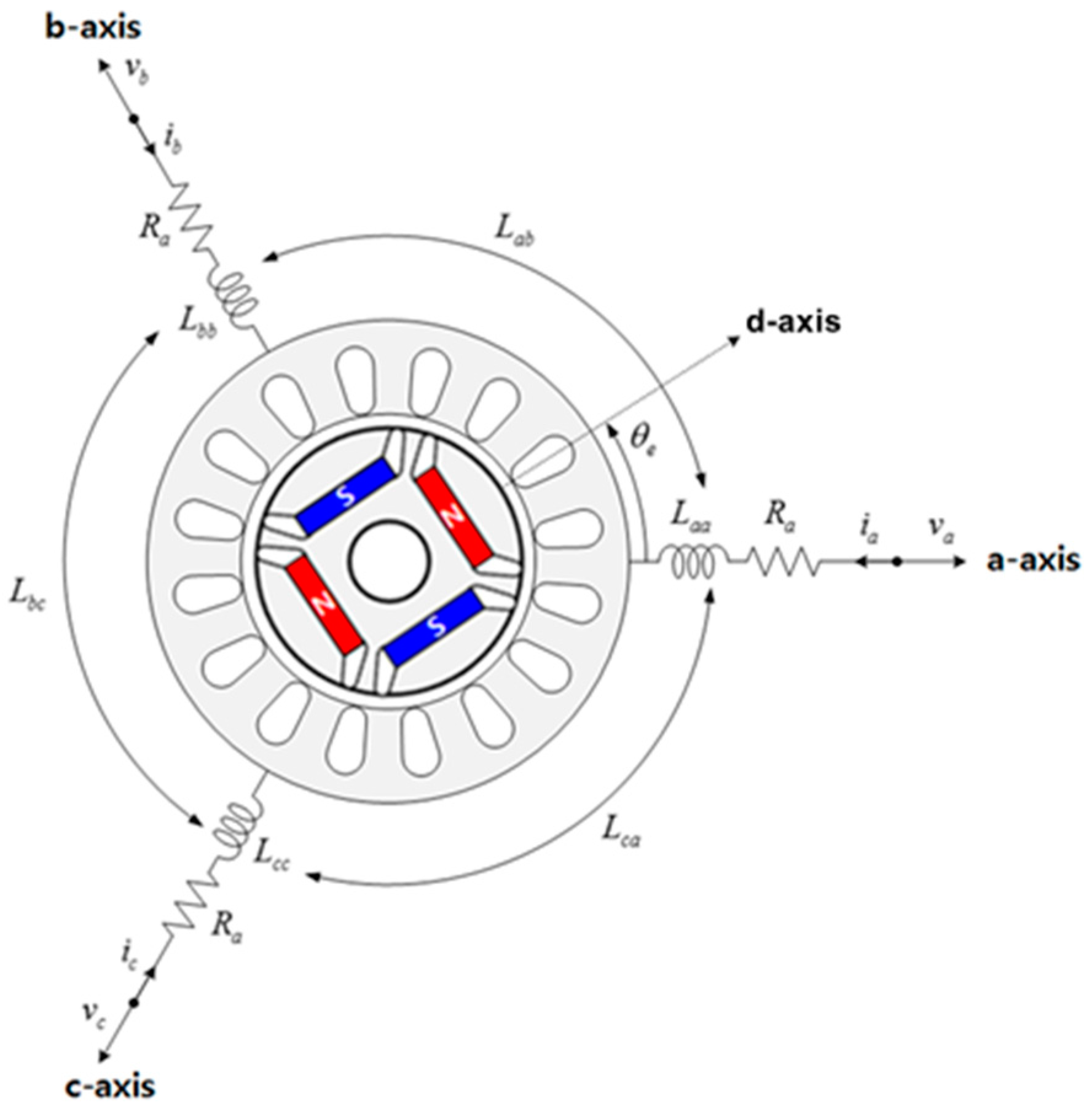
2. IPMSM Mathematic Model

2.1. IPMSM d-q Axis Voltage Equation

The IPMSM is structured as shown in Figure 1. The permanent magnets are inserted inside the rotor in a bar shape. Therefore, mechanical strength is improved. Additionally, permanent magnets are in the d-axis direction of the rotor, which results in higher magnetic reluctance and the magnetic flux produced by an electric current is difficult to flow. However, in the q-axis direction, there are no permanent magnets, resulting in lower magnetic reluctance, making it easier for magnetic flux due to electric current to flow. Therefore, IPMSM has a reverse saliency with the d-axis inductance larger than the q-axis inductance. Due to the reverse saliency, IPMSMs generate not only magnetic torque but also reluctance torque, thereby improving the output density of the motor.
The 3-phase voltage equation of IPMSM can be expressed as follows:
[ v a v b v c ] = [ R s + p L a a p L a b p L a c p L b a R s + p L b b p L b c p L c a p L c b R s + p L c c ] [ i a i b i c ] [ ω r Φ a sin θ ω r Φ a sin ( θ 2 π / 3 ) ω r Φ a sin ( θ + 2 π / 3 ) ]
where v a , v b , and v c are the 3-phase stator voltage, i a , i b , and i c are the 3-phase stator current, R s is stator resistance, L a a , L b b , and L c c are self-inductance, L a b , L a c , L b a , L b c , L c a , and L c b are mutual inductance, ω r is electrical stator angular velocity, Φ a is permanent magnet flux linkage, and p is differential operator, respectively.
In order to apply field-oriented vector control of IPMSM, the 3-phase voltage equation is transformed into the synchronous reference frame (d-q axes) through d-q axes transformation, and the relationship between the current vector (Ia) and d-q axes is shown in Figure 2 [18,19]. The d-axis is aligned with the permanent magnet flux direction, and the q-axis leads the d-axis by 90 electrical degrees as shown in Figure 2. The d-axis and q-axis currents represent the components of Is in the synchronous reference frame, and the voltage equation in the d-q axis coordinate system is represented in (2).
[ v d v q ] = [ R a + p L d ω r L q ω r L d R a + p L q ] [ i d i q ] + [ 0 ω r Φ a ]
where v d and v q are the d-q axis stator voltage, i d and i q are the d-q axis stator current, and L d and L q are the d-q axis stator inductance, respectively.

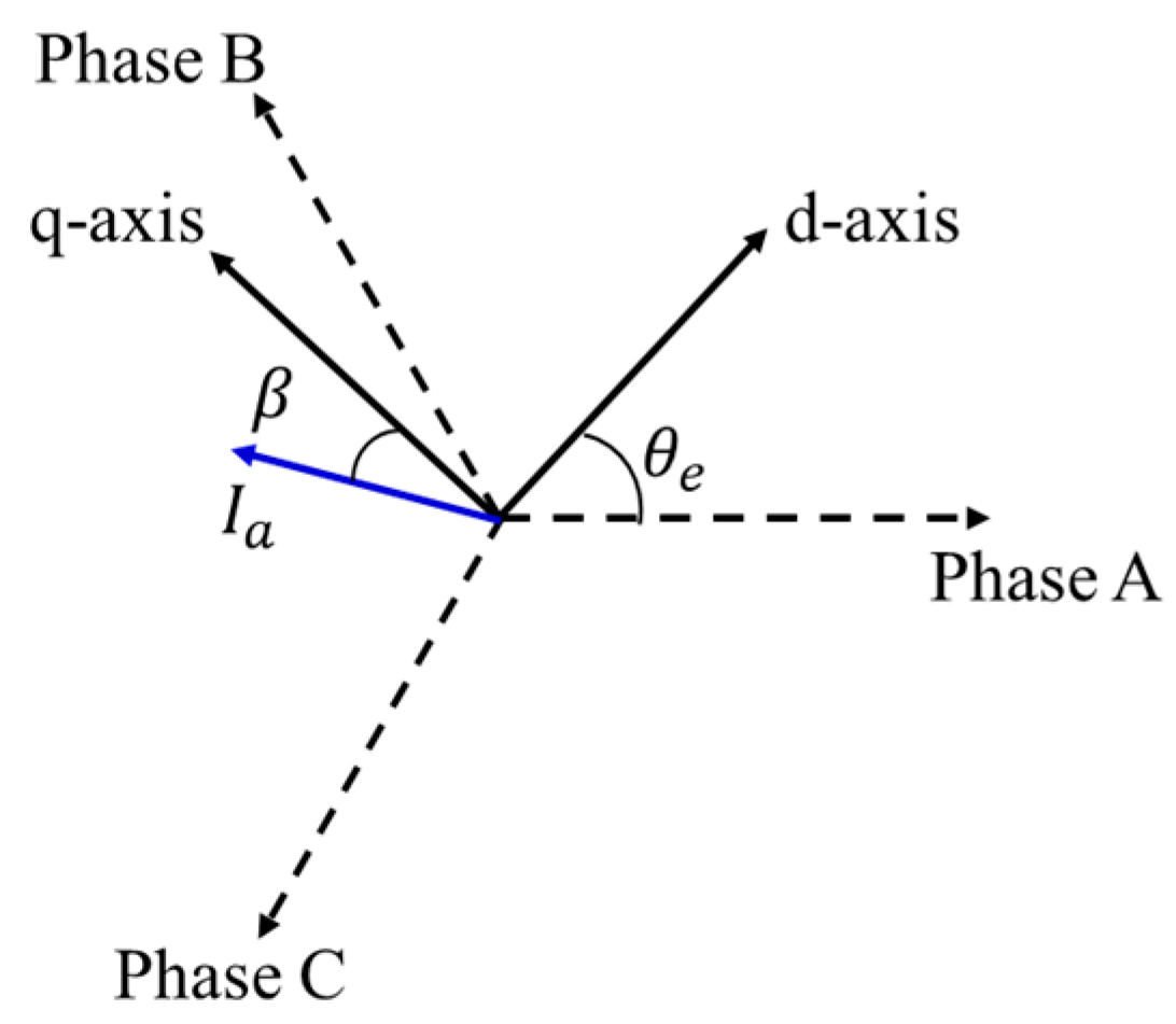
2.2. d-q Axis Current for Maximum Torque per Ampere (MTPA) Control

A permanent magnet synchronous motor (PMSM) always has a current phase that maximizes the torque generated for a given current. Operating at the point where maximum torque is consistently achieved with respect to the stator current is referred to as maximum torque per ampere (MTPA) control [20,21].
For calculating the phase current of MTPA, the torque equation of the IPMSM is expressed as follows:
T e = P 2 3 2 [ Φ a I a cos β + 1 2 ( L d L q ) I a 2 sin 2 β ]
where T e is the electrical motor torque, β is the current phase angle, respectively.
The operating point for maximum torque per ampere control can be obtained by partially differentiating (3), which depends on the magnitude and phase angle of the current, with respect to variable β . The value is the torque equation for a permanent magnet synchronous motor, equal to zero when differentiated with respect to the current phase angle, representing the operating point for maximum torque per ampere control. Therefore, the d-q axis current can be determined as shown in (4) and (5).
i d = Φ a 4 ( L q L d ) Φ a 2 16 ( L q L d ) 2 + I a m 2 2
i q = I a m 2 i d 2
where I a m is the maximum current.

3. Electrical Torque Estimator

In general, to obtain the electric torque of the IPMSM, a dynamo set or a lookup table can be used. However, these approaches require additional tests, which is time consuming and costly. Therefore, this paper proposes a method to estimate the torque using the output equation of IPMSM. The output equation of IPMSM is as follows:
P i n = 3 2 ( v d i d + v q i q ) = 3 2 { ( R a i d + p L d i d ω r L q i q ) i d + ( R a i q + p L q i q + ω r L d i d + ω r Φ a ) i q } = 3 2 { R a ( i d 2 + i q 2 ) + p ( L d i d + L q i q ) + ω r ( Φ a i q + L d i d i q L q i d i q ) }
where P i n is the input power.
In (6), the first term represents copper loss, the second term represents magnetic field energy, and the third term represents mechanical output. In the steady state, the magnetic field energy is constant and does not change, so the output power can be expressed as
P o u t = P i n P c P i P m
where P out is output power, P c is copper loss, P i is iron loss and P m is mechanical loss. The iron loss consists of eddy current loss and hysteresis loss. This can be expressed as follows [22]:
P i = P e d d y + P h y s t e r e s i s = K e f 2 B m a x 2 + K h f B m a x n K e ω m 2 + K h ω m
where K e is eddy current loss constant, K h is hysteresis loss constant, B m a x is maximum flux density, n is material dependent Steinmetz loss constant (1.6 to 2.0). Loss constants K e and K h are determined by the iron loss curve of steel lamination.
Total mechanical losses are the bearing and windage losses, which can be expressed by [11]
P m = P b e a r i n g + P w i n d a g e = 0.5 ω m k b F D b + 0.03125 ω m 3 π k c t k r ρ a i r D r 4 l r
where ω m is mechanical speed of the rotor, k b is bearing loss constant, F is force acting on the bearing, D b is bearing inner diameter, k ct is torque coefficient, k r is roughness coefficient, ρ a i r is density of air, D r is rotor diameter, L r is rotor length. However, mechanical losses are negligible because mechanical loss is very small compared to copper loss and iron loss.
Therefore, the output electrical torque can be represented by
T e = P o u t ω m = 3 2 ω m { ( v d i d + v q i q ) R a ( i d 2 i q 2 ) } ( K e ω m + K h )
The electric torque can be calculated from the d-q axis voltage and current parameter by (10). So, it is possible to estimate the electric torque of IPMSM without additional tests.

4. Online Parameter Tracking Methods

For vector control of IPMSM, the three-phase voltage equation of IPMSM was calculated by applying the Clarke transform and Park transform sequentially, which led to the d-q axes voltage equation as
v d = R a i d + d L d i d d t ω r L q i q
v q = R a i q + d L q i q d t + ω r L d i d + ω r Φ a
The torque equation of IPMSM is given as follows:
T e = 3 2 P 2 { Φ a i q + ( L d L q ) i d i q }
This paper proposes the estimation of d- and q-axis inductances through electrical and mechanical equation without information on magnetic flux. Magnetic flux fluctuates due to temperature and saturation. The proposed estimation has more accurate values because it can estimate d- and q-axis inductance regardless of magnetic flux.
The torque and d and q-axis currents at t = t 1 in (5) are T e ( t 1 ) , i d ( t 1 ) , and i q ( t 1 ) , respectively. At t = t 2 , T e ( t 2 ) , i d ( t 2 ) and i q ( t 2 ) can be written as
Δ T e = T e ( t 2 ) T e ( t 1 ) = 3 2 P 2 [ { Φ a i q + ( L d L q ) i d ( t 2 ) i q ( t 2 ) } { Φ a i q + ( L d L q ) i d ( t 1 ) i q ( t 1 ) } ]
If the q-axis current is controlled constant during t 1 ~ t 2 , the following expression can be obtained:
L d L q = 4 Δ T e 3 P i q Δ i d
Q-axis inductance can be expressed as follows in the steady state by (11):
L q = R a i d v d ω r i q
Therefore, L d and L q can be estimated by (15) and (16) by calculating Δ T e in (14).

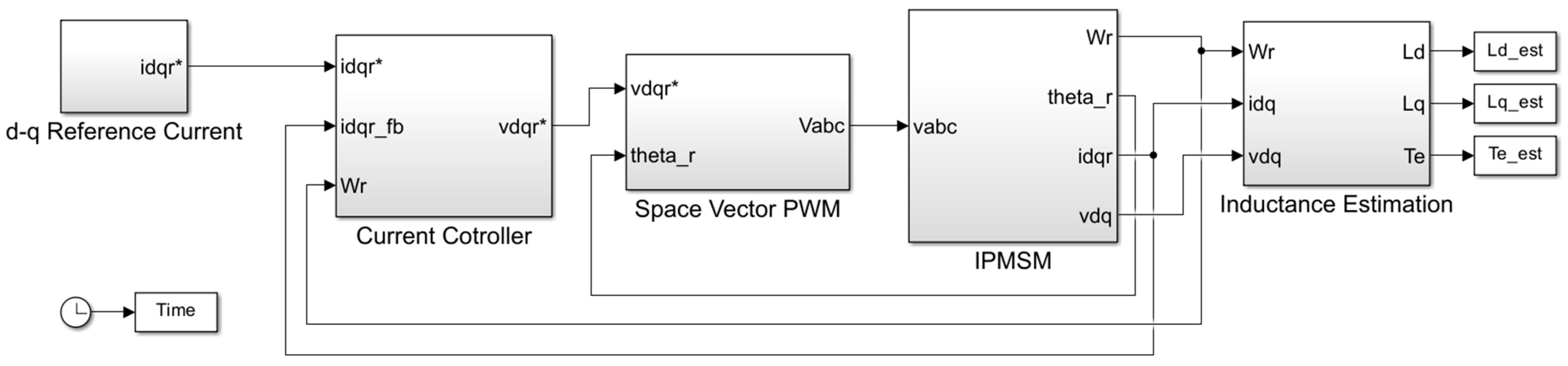
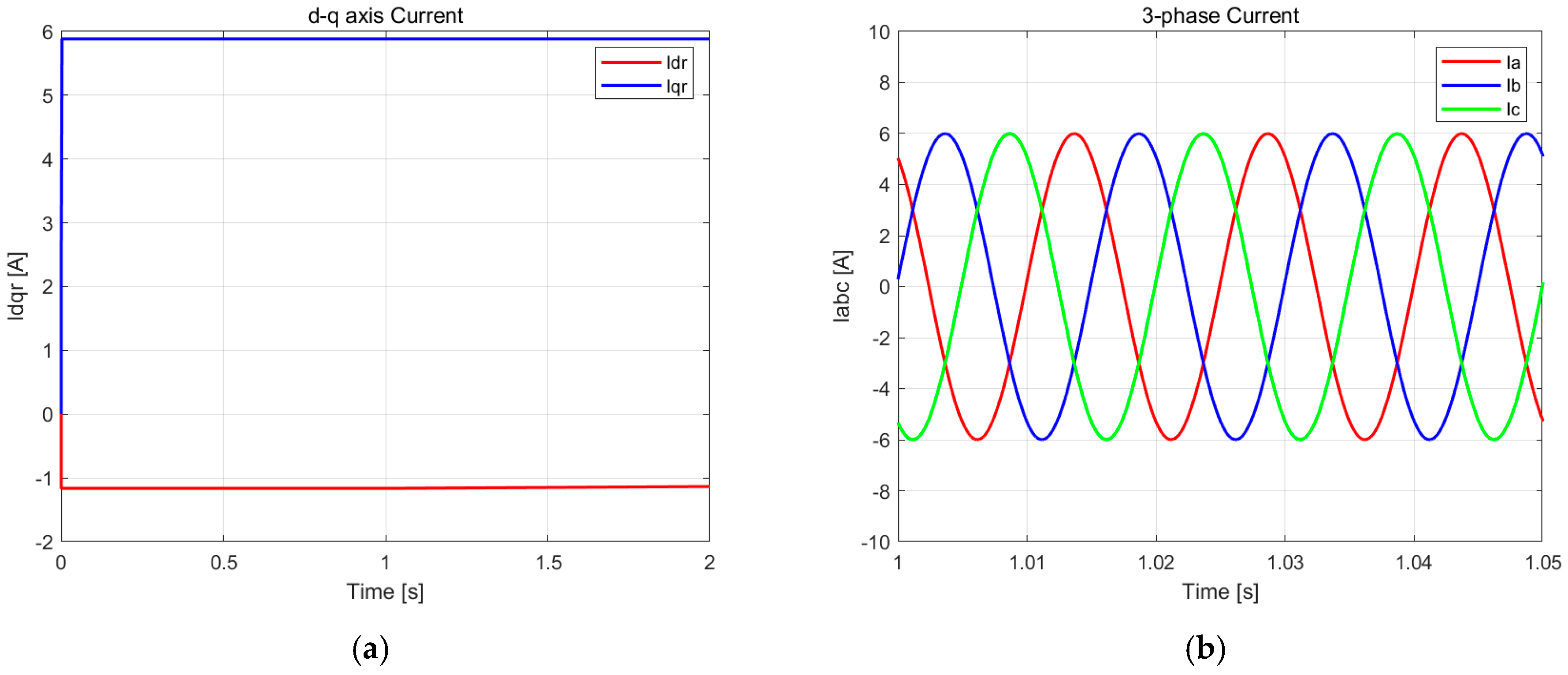
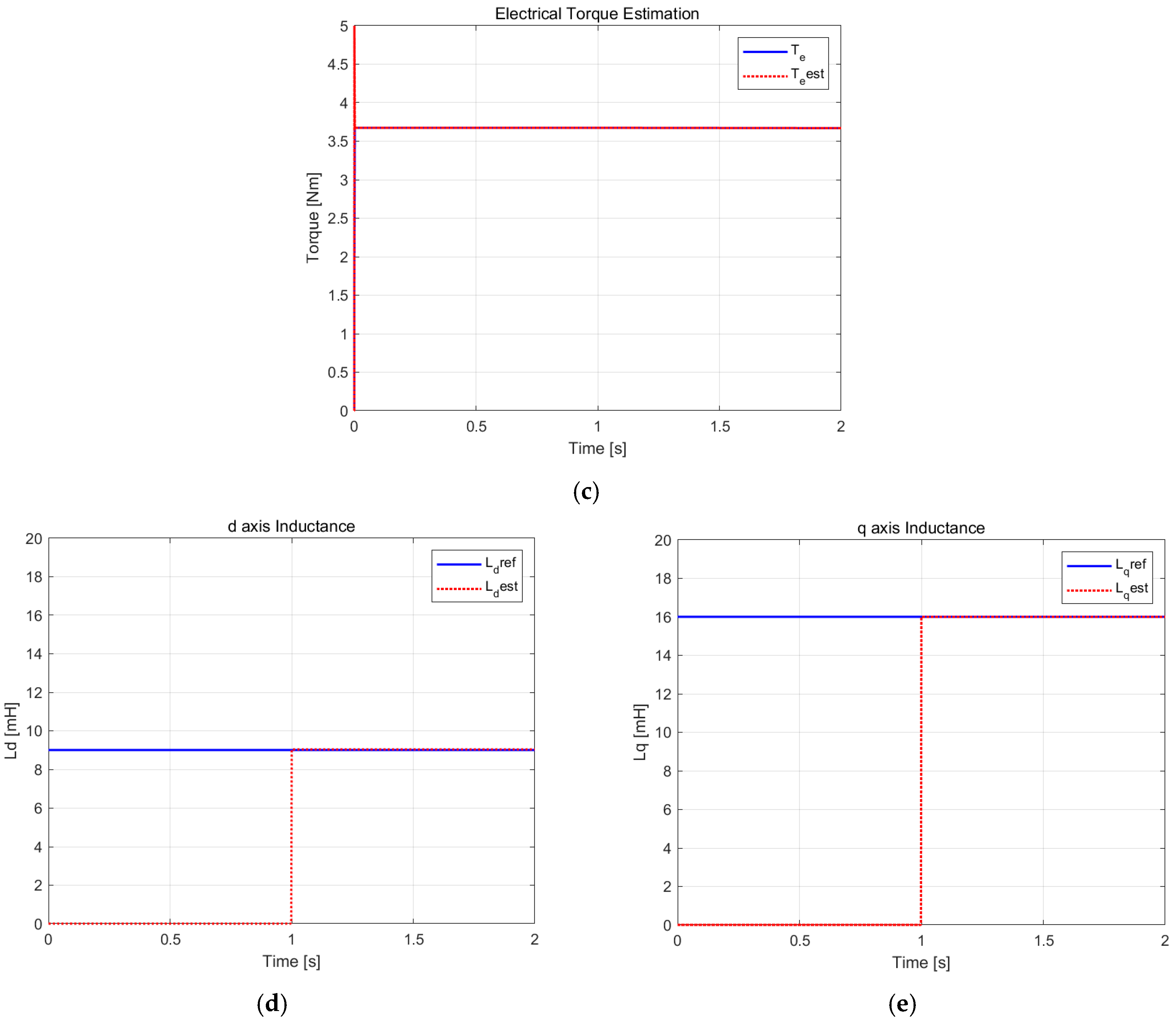
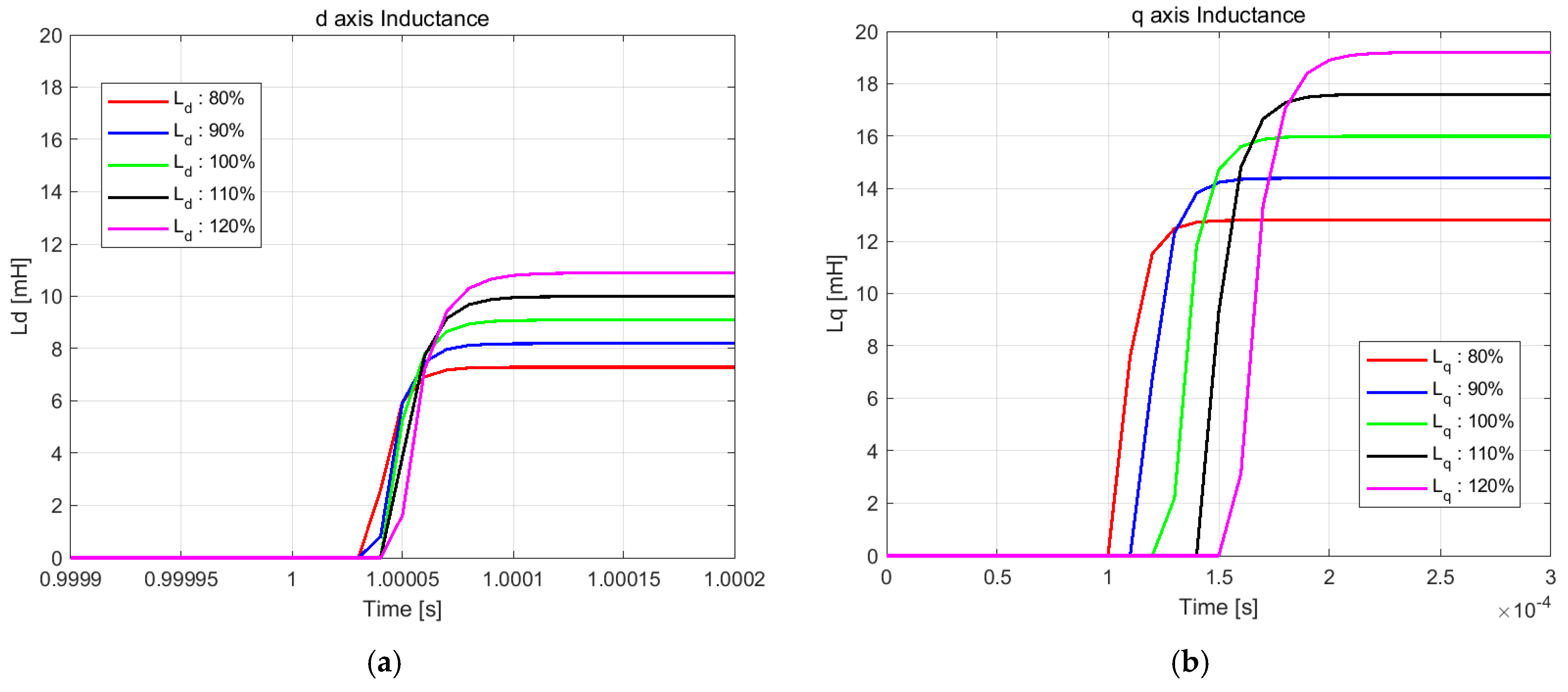
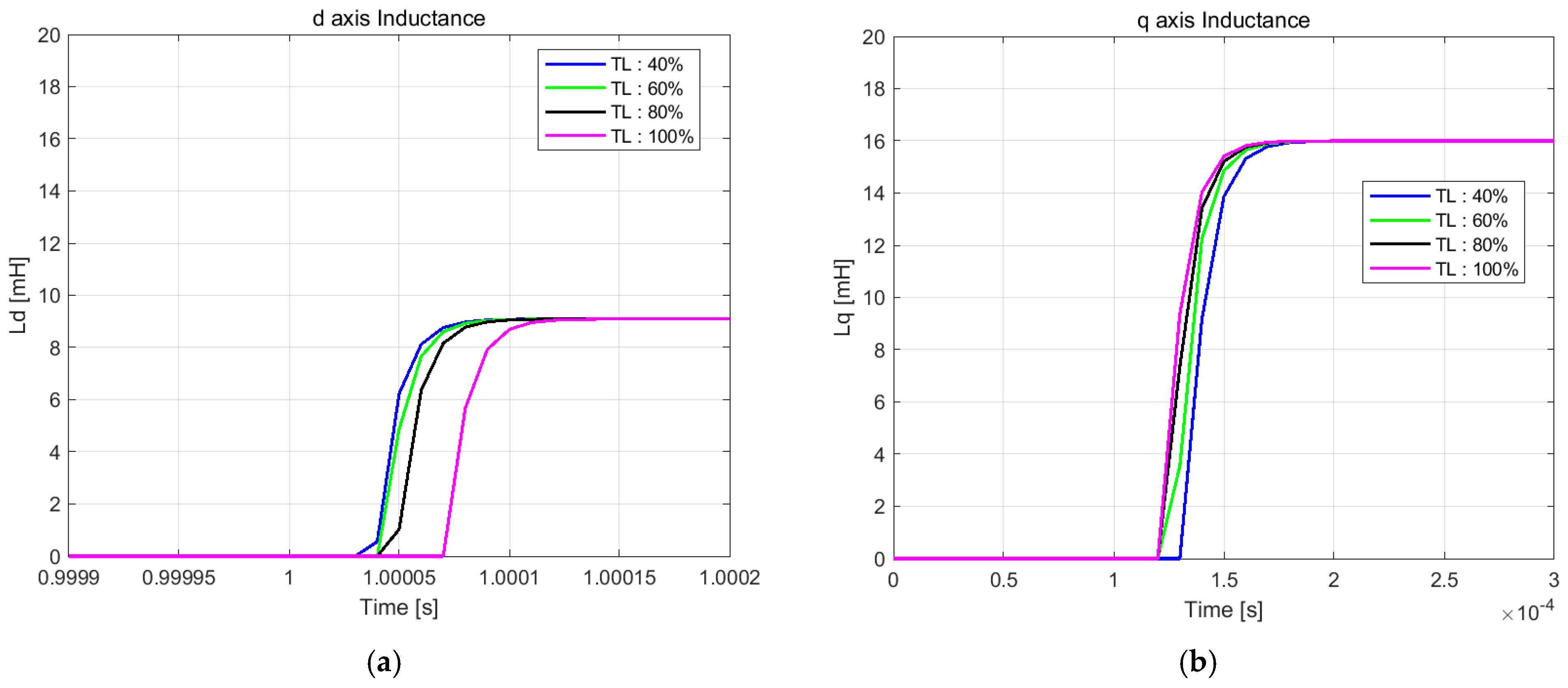
5. Simulation Results

To verify the proposed inductance estimation method, simulations are performed by MATLAB/Simulink R2023a. Figure 3 shows the MATLAB/Simulink blocks. The d-q axis current references are calculated to run the MTPA operation. The current references pass through the current controller to make voltage commands, and then input to the IPMSM after passing through the SVPWM block. Speed and position information for the IPMSM can be obtained from an encoder. Using the current and voltage in the rotating coordinate system, the motor’s torque is estimated, subsequently leading to the acquisition of parameter values for L d and L q . Inductance estimation is simulated to start 1 s after simulation initiation.
Table 1 shows the specifications of the flush-mounted permanent magnet synchronous motor (IPMSM) used in this study. The motor has four permanent magnets, a DC link voltage of 310 V, and a maximum current of 6 A. The maximum torque capacity is 3.6 Nm. It has a maximum torque of 3.6 Nm and a phase resistance of 0.511 Ω. It also has a d-axis inductance of 9 mH, a q-axis inductance of 13 mH, and a flux of 0.2 Wb induced by the permanent magnets.
Figure 4 shows the simulation results obtained using the algorithm proposed in this paper. Figure 4a shows the d-q axis current expressed in the rotor reference coordinate system. This current is the result of the control by the command current of the maximum torque/ampere (MTPA) control applying Equations (4) and (5). The results show that the current is well controlled. Figure 4b shows the three-phase current being applied to the motor, and it can be seen that the a, b, and c phases maintain a constant electrical phase difference of 120°. The magnitude of each phase current is 6 A, again showing good current control. Figure 4c compares the estimated torque obtained from Equation (10) with the actual torque, which can be calculated through Equation (13). The results show that the estimated torque is consistent with the actual torque, which confirms the reliability of the proposed estimation method. Figure 4d and Figure 4e show the estimation results of d-axis inductance and q-axis inductance, respectively. As can be seen from the figures, the inductance estimation starts 1 s after the start of the simulation, and it can be observed from the graphs that the estimated value shown by the red dashed line is consistent with the actual value shown by the blue solid line. This result confirms the accuracy of the inductance estimation in the proposed algorithm.
Figure 5 presents the inductance estimation results when d-q axis inductances are arbitrarily varied from 80% to 120% in simulation. As shown in Figure 5, the inductance estimation algorithm performs effectively despite the inductance variations. In the figure, one division of the time axis represents 50 μs, and it can be observed that the inductance estimation algorithm completes its computation within 50 μs. The estimation results demonstrate accuracy within 2% error bounds. Although not presented in these simulation results, both the d-q axis current control and torque estimation demonstrate performance characteristics comparable to those shown in Figure 4.
Figure 6 presents the inductance estimation results under motor load variations ranging from 40% to 100% of maximum torque in simulation. Consistent with the previous results, rapid inductance estimation is maintained under varying load conditions.

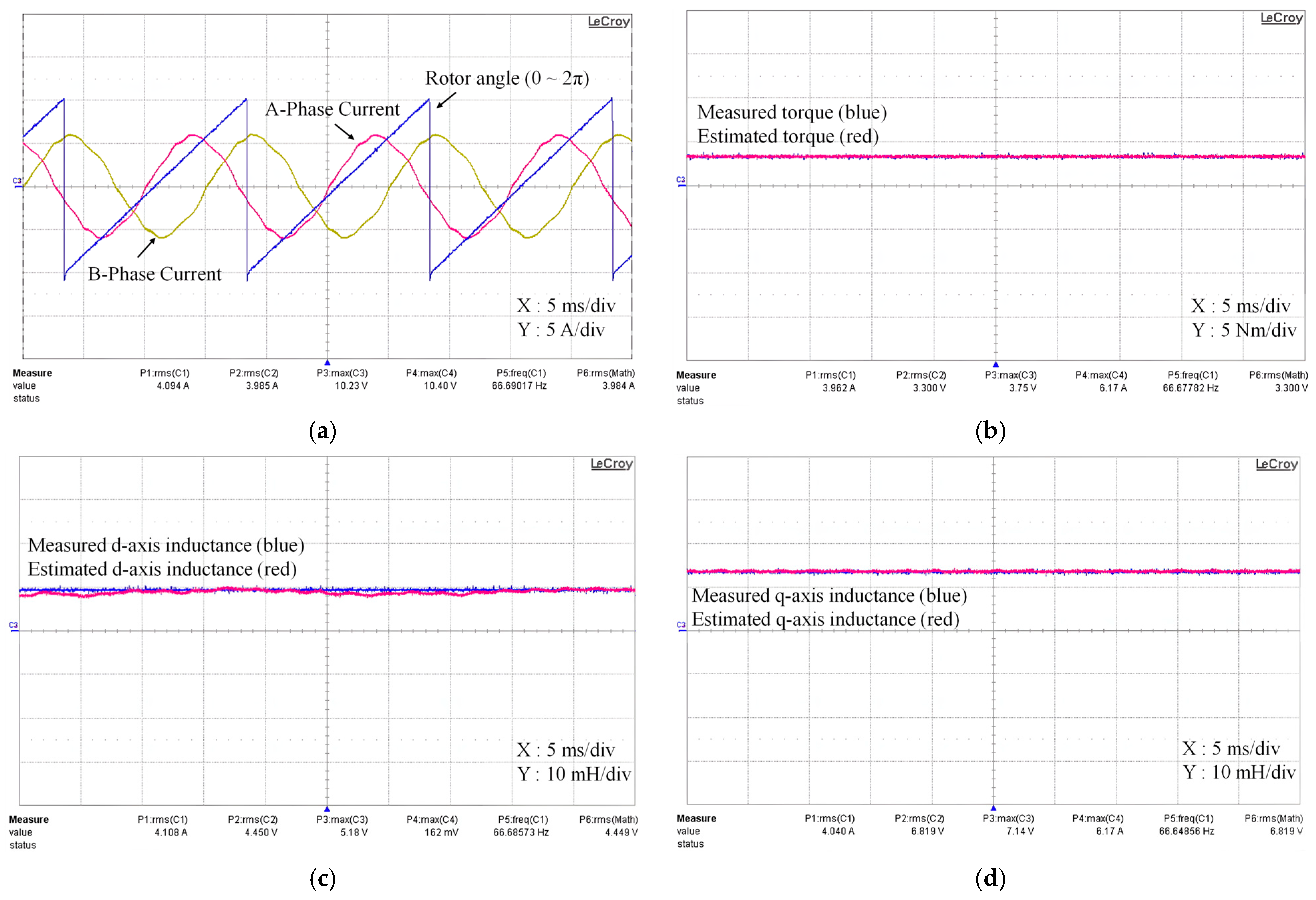
6. Experimental Results

A test configuration is set up as shown in Figure 7 to validate its performance. The specifications of the test IPMSM are presented in Table 1. And the test is performed at the base speed of 2000   [ rpm ] of IPMSM and I a = 6   [ A ] , b e t a = 7 ° for MTPA operation. DSP TMS320F28335 is used to drive the IPMSM and applied the load using a dynamometer.
Figure 8 presents the experimental results in detail to show the performance and accuracy of the proposed algorithm. Figure 8a shows the phase currents and electrical angles. In this graph, the red line represents the A-phase current and the yellow line represents the B-phase current. The electric angle, represented by the blue line, is calculated by measuring the phase difference between when the electric angle is 0 degrees and the moment when the A-phase current passes through 0. The measurement results show that the value of the electric angle is 7.00 degrees, which shows that the proposed algorithm can accurately estimate the phase relationship between the electric angle and the phase current. Figure 8b shows the motor torque and compares the measured torque with the torque estimated by the proposed method. Each bin on the vertical axis represents 5 Nm and is designed to provide a clear interpretation of the torque value. The blue line represents the reference torque measured by the dynamometer, while the red line represents the torque estimated by the algorithm. The two values are very similar, confirming that the proposed algorithm accurately estimates the motor torque and provides reliable performance. Figure 8c shows the d-axis inductance, where the blue line shows the actual value and the red line shows the estimated value. Figure 8d shows the q-axis inductance, and again, the blue line shows the actual value and the red line shows the estimated value. In both graphs, the scale of the vertical axis is set to 10 mH per bin, and the actual and estimated values are very similar, indicating that the proposed algorithm can estimate the d- and q-axis inductance values with high accuracy. This result verifies that the proposed algorithm performs reliably and consistently under the operating conditions of the motor.

7. Conclusions

In this paper, this newly developed method for estimating L d and L q from electrical and mechanical equations is proposed. The proposed parameter estimation method is derived from electrical torque estimator. The method can be easily implemented through the d-q axis voltage and current. Furthermore, it is not affected by the nonlinearity of the magnetic flux, providing higher accuracy. MATLAB/Simulink simulations demonstrate the practicality and effectiveness of the algorithm, and a test motor confirms the suitability of the parameter estimation technique.

Author Contributions

Conceptualization, H.-J.P. and H.-W.A.; methodology, H.-J.P. and H.-W.A.; software, H.-J.P., S.B. and H.-W.A.; validation, H.-J.P., S.B. and H.-W.A.; formal analysis, H.-W.A.; investigation, H.-W.A.; resources, H.-W.A.; data curation, H.-W.A.; writing—original draft preparation, H.-W.A.; writing—review and editing, S.B. and H.-J.P.; visualization, S.B. and H.-J.P.; supervision, H.-J.P.; project administration, H.-J.P.; funding acquisition, H.-J.P. All authors have read and agreed to the published version of the manuscript.

Funding

This research was supported by “Regional Innovation Strategy (RIS)” through the National Research Foundation of Korea (NRF) funded by the Ministry of Education (MOE) (2021RIS-004).

Data Availability Statement

The original contributions presented in the study are included in the article, further inquiries can be directed to the corresponding author.

Conflicts of Interest

The authors declare no conflicts of interest.

References

  1. Liu, X.; Chen, H.; Zhao, J.; Belahcen, A. Research on the performances and parameters of interior PMSM used for electric vehicles. IEEE Trans. Ind. Electron. 2016, 63, 3533–3545. [Google Scholar] [CrossRef]
  2. Lee, K.D.; Lee, J.; Lee, H.W. Inductance Calculation of Flux Concentrating Permanent Magnet Motor Through Nonlinear Magnetic Equivalent Circuit. IEEE Trans. Magn. 2015, 51, 529–551. [Google Scholar] [CrossRef]
  3. Meessen, M.J.; Thelin, P.; Soulard, J.; Lomonova, E.A. Inductance Calculations of Permanent-Magnet Synchronous Machines Including Flux Change and Self- and Cross-Saturations. IEEE Trans. Magn. 2008, 44, 2324–2331. [Google Scholar] [CrossRef]
  4. Rahman, K.M.; Hiti, S. Identification of Machine Parameters of a Synchronous Motor. IEEE Trans. Ind. Appl. 2005, 41, 557–565. [Google Scholar] [CrossRef]
  5. Kim, H.S.; Sul, S.K. Real-Time Torque Control of IPMSM Under Flux Variations. IEEE J. Emerg. Sel. Topics Power Electron. 2022, 10, 3345–3356. [Google Scholar] [CrossRef]
  6. Erturk, F.; Akin, B. Spatial inductance estimation for current loop auto-tuning in IPMSM self-commissioning. IEEE Trans. Ind. Electron. 2020, 67, 3911–3920. [Google Scholar] [CrossRef]
  7. Chen, Z.; Qiu, J.; Jin, M. Adaptive finite-control-set model predictive current control for IPMSM drives with inductance variation. IET Electr. Power Appl. 2017, 11, 874–884. [Google Scholar] [CrossRef]
  8. Morimoto, S.; Sanada, M.; Takeda, Y. Mechanical Sensorless Drives of IPMSM with Online Parameter Identification. IEEE Trans. Ind. Appl. 2006, 42, 1241–1248. [Google Scholar] [CrossRef]
  9. Ahn, H.; Park, H.; Kim, C.; Lee, H. A Review of State-of-the-Art Techniques for PMSM Parameter Identification. J. Electr. Eng. Technol. 2020, 15, 1177–1187. [Google Scholar] [CrossRef]
  10. Boje, E.S.; Balda, J.C.; Harley, R.G.; Beck, R.C. Time-domain Identification of Synchronous Machine Parameters from Simple Standstill Test. IEEE Trans. Energy Convers. 1990, 5, 164–175. [Google Scholar] [CrossRef] [PubMed]
  11. Cavagnino, A.; Lazzari, M.; Profumo, F.; Tenconi, A. Axial Flux Interior PM Synchronous Motor: Parameters Identification and Steady-State Performance Measurements. IEEE Trans. Ind. Appl. 2000, 36, 1581–1588. [Google Scholar]
  12. Choi, C.; Lee, W.; Kwon, S.O.; Hong, J.P. Experimental Estimation of Inductance for Interior Permanent Magnet Synchronous Machine Considering Temperature Distribution. IEEE Trans. Magn. 2013, 49, 2990–2996. [Google Scholar] [CrossRef]
  13. Štumberger, B.; Štumberger, G.; Dolinar, D.; Hamler, A.; Trlep, M. Evaluation of Saturation and Cross-Magnetization Effects in Interior Permanent-Magnet Synchronous Motor. IEEE Trans. Ind. Appl. 2003, 39, 1264–1271. [Google Scholar] [CrossRef]
  14. Shuang, B.; Zhu, Z.Q. A Novel Method for Estimating the High Frequency Incremental DQ-Axis and Cross-Coupling Inductances in Interior Permanent Magnet Synchronous Motor. IEEE Trans. Ind. Appl. 2021, 57, 4913–4923. [Google Scholar] [CrossRef]
  15. Mohamed, Y.A.R.I.; Lee, T.K. Adaptive self-tuning MTPA vector controller for IPMSM drive system. IEEE Trans. Energy Convers. 2006, 21, 636–644. [Google Scholar] [CrossRef]
  16. Liu, K.; Zhu, Z.Q. Online Estimation of the Rotor Flux Linkage and Voltage-Source Inverter Nonlinearity in Permanent Magnet Synchronous Machine Drives. IEEE Trans. Power Electron. 2014, 29, 418–427. [Google Scholar] [CrossRef]
  17. Shi, Y.; Sun, K.; Huang, L.; Li, Y. Online Identification of Permanent Magnet Flux Based on Extended Kalman Filter for IPMSM Drive with Position Sensorless Control. IEEE Trans. Ind. Electron. 2012, 59, 4169–4178. [Google Scholar] [CrossRef]
  18. Nicola, M.; Nicola, C.-I. Improvement Performances of Sensorless Control for PMSM Based on FOC Strategy Using Luenberger Observer, Sine Cosine Algorithm, and RL-TD3 Agent. In Proceedings of the 2023 International Conference on Electromechanical and Energy Systems (SIELMEN), Craiova, Romania, 11–13 October 2023; pp. 1–7. [Google Scholar]
  19. Ren, W.; Wu, Y.; Du, R. A Vector Control System of PMSM with the Assistance of Fuzzy PID Controller. In Proceedings of the 2020 39th Chinese Control Conference (CCC), Shenyang, China, 27–29 July 2020; pp. 2205–2210. [Google Scholar]
  20. Alzayed, M.; Chaoui, H.; Farajpour, Y. Dynamic Direct Voltage MTPA Current Sensorless Drives for Interior PMSM-Based Electric Vehicles. IEEE Trans. Veh. Technol. 2023, 72, 3175–3185. [Google Scholar] [CrossRef]
  21. Alzayed, M.; Chaoui, H. Direct Voltage MTPA Speed Control of IPMSM-Based Electric Vehicles. IEEE Access 2023, 11, 33858–33871. [Google Scholar] [CrossRef]
  22. Pyrhonen, J.; Jokien, T.; Hrabovcova, V. Design of Rotating Electrical Machines; John Wiely & Sons, Ltd.: Hoboken, NJ, USA, 2008. [Google Scholar]
Figure 1. Cross-section of interior permanent magnet synchronous motor.
Energies 18 00469 g001
Figure 2. Current vector representation in d-q reference frame.
Energies 18 00469 g002
Figure 3. MATLAB/Simulink block diagram for online parameter identification simulation.
Energies 18 00469 g003
Figure 4. Simulation results. (a) d- and q-axis current in the rotor frame. (b) Three-phase current. (c) Electrical torque estimation. (d) d-axis inductance estimation. (e) q-axis inductance estimation.
Energies 18 00469 g004aEnergies 18 00469 g004b
Figure 5. Simulation results: inductance estimation under varying d-q axis inductances. (a) d-axis inductance estimation. (b) q-axis inductance estimation.
Energies 18 00469 g005
Figure 6. Simulation results: inductance estimation under varying load torque. (a) d-axis inductance estimation. (b) q-axis inductance estimation.
Energies 18 00469 g006
Figure 7. Experimental results.
Energies 18 00469 g007
Figure 8. Experimental results. (a) Three-phase current. (b) Electrical torque estimation. (c) d-axis inductance estimation. (d) q-axis inductance estimation.
Energies 18 00469 g008
Table 1. The specifications of IPMSM.
DescriptionValueUnit
Pole4-
DC Link Voltage310V
Max. Current6A
Max. Torque3.6Nm
Phase Resistance0.511Ohm
d-axis Inductance9mH
q-axis Inductance13mH
Magnetic Flux0.2Wb
Disclaimer/Publisher’s Note: The statements, opinions and data contained in all publications are solely those of the individual author(s) and contributor(s) and not of MDPI and/or the editor(s). MDPI and/or the editor(s) disclaim responsibility for any injury to people or property resulting from any ideas, methods, instructions or products referred to in the content.

