Article

Smooth Droop Control Strategy for Multi-Functional Inverters in Microgrids Considering Unplanned Off-Grid Transition and Dynamic Unbalanced Loads

by
Jinhao Shen
1,
Hua Zhang
1,
Xueneng Su
1,
Yiwen Gao
1,
Kun Zheng
1,
Cheng Long
1 and
Xinbo Liu
2,*
1
State Grid Sichuan Electric Power Research Institute, Chengdu 610041, China
2
Sichuan Energy Internet Research Institute, Tsinghua University, Beijing 100190, China
*
Author to whom correspondence should be addressed.
Energies 2025, 18(23), 6161; https://doi.org/10.3390/en18236161
Submission received: 15 October 2025 / Revised: 12 November 2025 / Accepted: 13 November 2025 / Published: 24 November 2025

Abstract

If unplanned off-grid events occur in microgrids, stable operation is disrupted. In particular, dynamic unbalanced loads, power pulse, and voltage changes also lead to system instability. To overcome these issues, this paper develops a smooth droop control strategy for multi-functional inverters. By introducing a QPR (quasi-proportional resonant) controller, the load voltage regulator is designed to compensate for the harmonic and unbalanced voltages of microgrids. Compared with traditional strategies, the proposed multi-functional inverter can reduce voltage pulses by more than 60%, and the off-grid voltage THD (total harmonic distortion) is decreased from 7% to less than 3%. At the same time, dynamic unbalanced loads and non-linear dynamic loads are both considered, and the derived strategy achieves smoother grid-connected and off-grid switching. In grid-connected mode (the microgrid connects to the distribution network at the PCC), the peak voltages and overshoots across transitions are definitely decreased, and continuous monitoring shows that the grid’s current THD stays steadily below 3%. This meets compatibility requirements, avoids harmonic interference on distribution networks, and follows the core principle of IEC TS 62898-1:2023. The simulation and experimental results verify the effectiveness of the proposed multi-function inverter control strategy for grid-connected inverters.

1. Introduction

Microgrids consist of distributed generation, dynamic loads, and energy storage systems and are developing rapidly in modern power systems [1]. When the grid fails due to major natural disasters or other factors, microgrids need to switch smoothly from grid-connected mode to off-grid mode, and it is also necessary to ensure continuous power supply for critical loads. After an unplanned off-grid event of a microgrid, it shall enter island mode to maintain operation, ensure microgrid stability through frequency and voltage regulation as well as adapting protection parameters, and compliance with power quality standards IEC TS 62898-1:2023 [2]. Thus, grid-connected inverters in microgrids are required to have multi-mode switching capability [3]. However, most studies about grid-connected and off-grid switching inverters in microgrids are carried out under linear loads, while there are few studies that take dynamic unbalanced loads and non-linear dynamic loads into account. When an inverter operates with non-linear loads and when grid support at the grid connection point is lost, the voltage experiences distortions and three-phase imbalances, poor voltage quality does not conform to common electricity standards, and even the effective power supply for important loads fails. Therefore, it is essential to enable microgrids to disconnect smoothly from the grid during unplanned off-grid events and, simultaneously, guarantee uninterrupted power supply for important loads [4].
Currently, master–slave architecture microgrids are widely adopted due to their maturity and simplicity. In grid-connected mode, the current control of the main inverter provides stable and high-quality active grid-connected current. In off-grid mode, the voltage control of the converter establishes qualified voltage, supplying power to loads instead of the grid. The control objectives of the main inverter are quite different in grid-connected mode and off-grid mode, resulting in voltage fluctuations during mode switching. If unplanned off-grid events happen, then control strategies are adjusted after the off-grid mode is detected. However, during the inspection period, microgrids lose the support of the grid, leading to imbalances among the inverter outputs, and then load demands emerge. These issues deteriorate the AC bus voltage fluctuations in microgrids, severely affecting loads [5]. In addition, when the inverter operates with non-linear and unbalanced loads, the AC bus voltage of microgrids is more prone to distortion and three-phase imbalances in off-grid mode.
When the inverter changes from current-source control to voltage-source control, inconsistent control references usually cause transient impacts on currents and voltages. To address this transient shock issue, Reference [6] proposes an indirect-current-based control strategy. The strategy includes a capacitor voltage control loop, a limiter, an external grid current loop, and an internal capacitor current loop. Limiters and a compensator are designed to reduce transient impacts and achieve smooth off-grid switching. However, using a limiter may reduce the control accuracy of the AC bus voltage and affect the system’s dynamic response. To improve the dynamic responses of microgrids during the transition from grid-connected mode to off-grid mode, References [7,8] propose a feed-forward-based control strategy which achieves smooth switching between the two modes. Nevertheless, the strategy does not consider the impact of distributed generation fluctuations and load changes on the given references. Moreover, voltage is highly sensitive, making the parameter design of the feed-forward controller relatively complex.
In addition, various advanced non-linear control algorithms have been applied to smooth the procedures from grid connection to disconnections, such as model predictive control [9], fuzzy logic control [10], and adaptive sliding mode control [11]. These algorithms offer strong robustness and great dynamic performance. However, sliding mode controllers may still cause fluctuations in voltage frequency and amplitude. Furthermore, these non-linear control methods always require establishing complex and accurate mathematical models, which makes control parameter tuning challenging and limits their practical engineering applications. To solve the voltage/current transients and power imbalance issues in microgrids during unplanned off-grid periods, Reference [12] proposes a coordinated control strategy. The strategy combines stepwise load shedding and dynamic PQ regulation, constrained by the proportional characteristics of battery energy storage systems (BESs). Through coordinated power regulation between master and slave BES units, it achieves smooth transitions during unplanned off-grid switching. Reference [13] proposes a grid-forming (GFM) inverter controller without Phase-Locked Loop (PLL). Using an active synchronization control strategy and multi-device coordination method, it realizes fast and stable synchronization of microgrids during grid connection-to-disconnection transitions, avoiding phase jumps and grid disturbance replication. Reference [14] proposes a detection method based on dual criteria: PCC current zero-crossing and system frequency fluctuation. By autonomously switching between power calculation modes, this method achieves power balance control during sudden off-grid events, avoids power imbalances, and enhances the stability of microgrids without grid support. Additionally, it addresses the low-inertia issue of microgrids and improves stability during unplanned off-grid events by constructing a unified framework for device-level control and grid-level operation. However, none of the above studies fully consider voltage distortion, three-phase imbalances, and dynamic non-linear loads in microgrids.
Overall, research on unplanned switching still faces two major bottlenecks. The first one is the difficulty in suppressing transient impacts during control mode switching between grid-connected and off-grid modes. The second one is a lack of power quality assurance mechanisms under non-linear loads.
To ensure uninterrupted power supply to critical loads in microgrids, this paper proposes a multi-mode droop control strategy for unplanned off-grid and planned reconnections, considering non-linear and unbalanced loads, unplanned off-grid events (caused by severe grid faults), and planned reconnections (after fault recovery). By adding a voltage stability controller and harmonic compensation, the derived strategy suppresses AC bus voltage fluctuations and ensures smooth transitions during grid disconnection. It also establishes qualified AC bus voltage in independent off-grid mode (with non-linear and unbalanced loads) to achieve continuous power supply. When the grid recovers, pre-synchronization control technology is used to realize impact-free, smooth, and seamless reconnection.
This paper is summarized as follows: Firstly, a quasi-proportional resonant (QPR) controller is introduced to compensate for harmonic and unbalanced voltages in off-grid mode. This ensures that the total harmonic distortion (THD) of the inverter output voltage meets the standards. Secondly, a load voltage regulator is designed to make the outer-loop output of the voltage controller nearly identical in both off-grid and grid-connected modes, enabling smoother grid-connected-to-off-grid switching. The regulator also maintains the load currents. Additionally, grid current feed-forward and current compensation are incorporated to limit sudden changes in the inner current loop references. During off-grid detection, the reference is kept equal to the sum of the rated load current and steady-state capacitor current, stabilizing the inverter output voltages. Finally, simulation and experimental results show that the proposed strategy enables the inverter to operate stably in both grid-connected and off-grid modes, achieving smooth and seamless switching for both active and passive grid connection/disconnection.

2. Microgrid Structure and Basic Principles of Grid-Connected and Off-Grid Switching

A simplified diagram of microgrids is shown in Figure 1, where the DC side is represented by a constant DC source and the three-phase inverter is the main inverter. The AC side consists of an LCL (inductor–capacitor–inductor) filter, non-linear loads, unbalanced loads, linear loads, a grid-side instantaneous protection switch S1, a microgrid controllable protection switch S2, and the utility grid. Here, Lf is the inverter-side inductance, and Lg is the grid-side inductance. udc stands for DC bus voltage. Cn is the filter capacitor, and Rf and Rg are the parasitic resistances of the filter inductor. Rc is the damping resistance connected in series with the filter capacitor. id* and iq* are the current reference values of the dq axes. ugn (n = a, b, c) represents grid voltage, uin (n = a, b, c) is the inverter-side output voltage, ucn (n = a, b, c) is the filter capacitor voltage, isn (n = a, b, c) is the inverter output current, ign (n = a, b, c) is the grid-connected current, iLn (n = a, b, c) is the current of non-linear and unbalanced loads, and San (n = 0, 1) denotes control-switching signals. Specifically, Sa0 indicates that the multi-function inverter operates in grid-connected mode, with grid-connected current control. Space Vector Pulse Width Modulation (SVPWM) is used to control inverters, enabling precise regulation of output voltage and current.
The main working modes of the multi-functional inverter and the relationships of switch states are shown in Figure 2. Before planned grid connection, the inverter initiates pre-synchronization control. When the amplitude and phase of the point-of-common-coupling (PCC) voltage uPCC matches the grid, a grid-connection signal is issued. At this time, both switches S1 and S2 are closed to enable seamless and smooth planned grid connection. After connection, uPCC is supported by the grid. In the event of a sudden grid fault, S2 opens, and the microgrid loses grid support. The off-grid detection module identifies the off-grid state after a detection period. During this period, the inverter remains in current control mode, outputting specified power. Due to the imbalance between the inverter output power and load demand, and the loss of grid clamping effect on uPCC, the PCC voltage may suddenly fluctuate or even oscillate unstably, degrading load power quality. Once off-grid detection is complete, an off-grid signal is sent, and S1 opens. The inverter then switches from current control to voltage control, and uPCC is supported by the inverter. When the grid recovers, pre-synchronization control restarts. Upon issuing the grid-connection signal, S1 and S2 are closed to initiate reconnection.
When the inverter operates in grid-connected mode, the output current isn (n = a, b, c) at the inverter side satisfies
i s n = i L n + i c n + i gn
where iLn, icn, and ign (n = a, b, c) represent the three-phase load current, the capacitor current, and the grid-connected current, respectively.
When a grid fault occurs, microgrids disconnect from the grid and enter an off-grid state. At this time, the grid-connected current becomes zero, and the relationship of isn (n = a, b, c) is as follows:
i s n = i L n + i c n
In the traditional constant-voltage and -frequency control strategy, the d-axis component is taken as an example for analysis. As shown in (1) and (2), when a grid fault and unplanned off-grid event happen, microgrids lose grid support. During the off-grid detection period, the multi-function inverter remains in current control mode, causing a sudden change in the filter inductance current isd. Since the given reference value isdref for the inverter output current remains unchanged, the difference between isd and isdref also changes abruptly. This mismatch between inverter output power and load demand power leads to excess power flowing into loads, resulting in rises in load voltages.

3. Improved PQ/VF Control

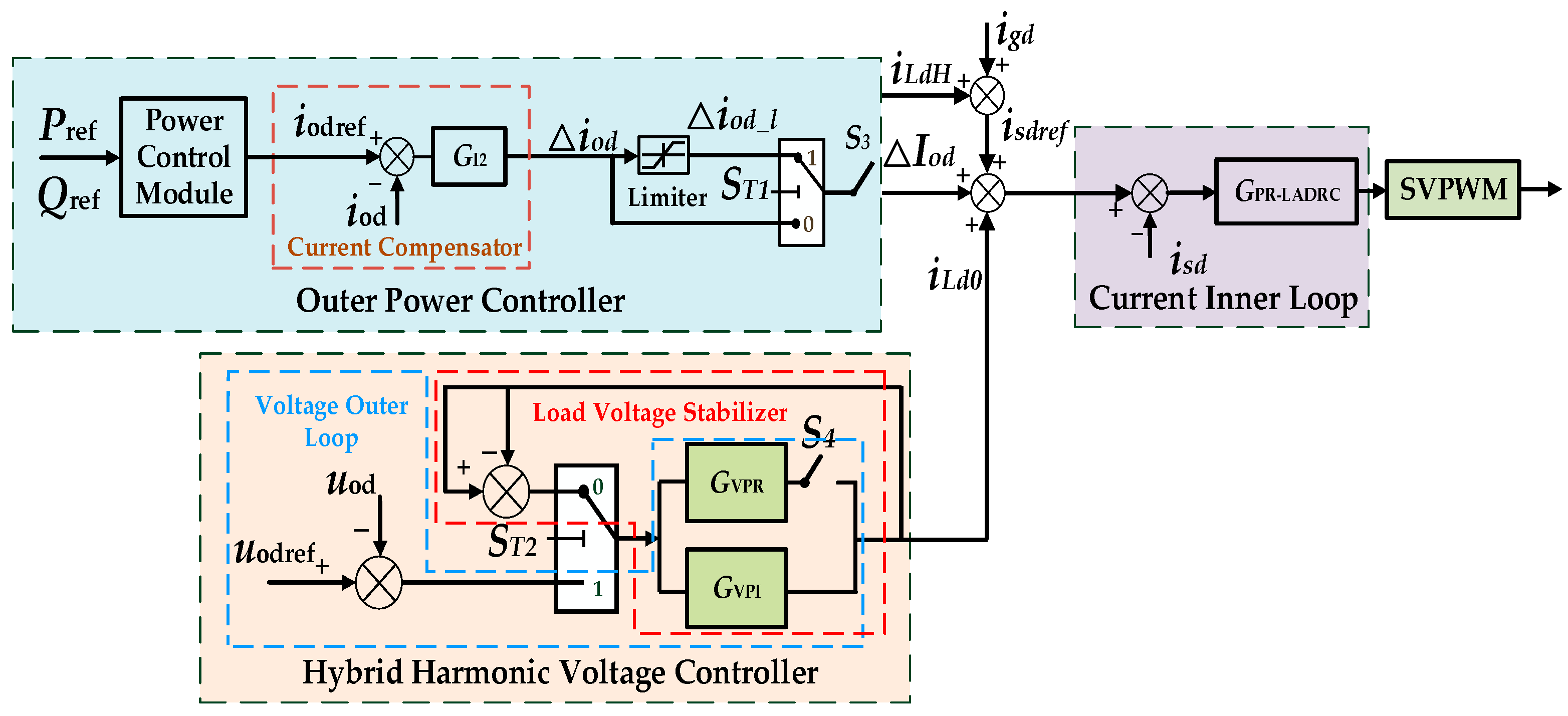
This paper improves the traditional PQ/VF (Voltage Frequency Control/Power Quality Control) method to ensure smooth changing from grid-connected to off-grid modes during unplanned off-grid events. Firstly, a load voltage regulator is designed to make the output of the voltage controller nearly identical in both off-grid mode and grid-connected mode, enabling smoother switching. Secondly, a composite controller combining PI (proportional–integral) and QPR is introduced to compensate for harmonic and unbalanced voltages during off-grid mode, guaranteeing that the total harmonic distortion (THD) of the inverter output voltage meets standards when switching to off-grid mode. Additionally, the load voltage regulator maintains load currents at the rated values. Grid current feed-forward igd and a current compensator are introduced to limit sudden changes in the inner current loop reference isdref. This ensures that isdref equals the sum of the rated load current iLd and steady-state capacitor current icd during off-grid detection, thereby stabilizing the inverter output voltage.
The improved d-axis control structure for PQ/VF switching is shown in Figure 3. The control structure includes an outer voltage controller, an outer power controller, an inner current controller, and a power quality detection module. SVPWM is utilized to control inverters.

3.1. Load Voltage Regulator

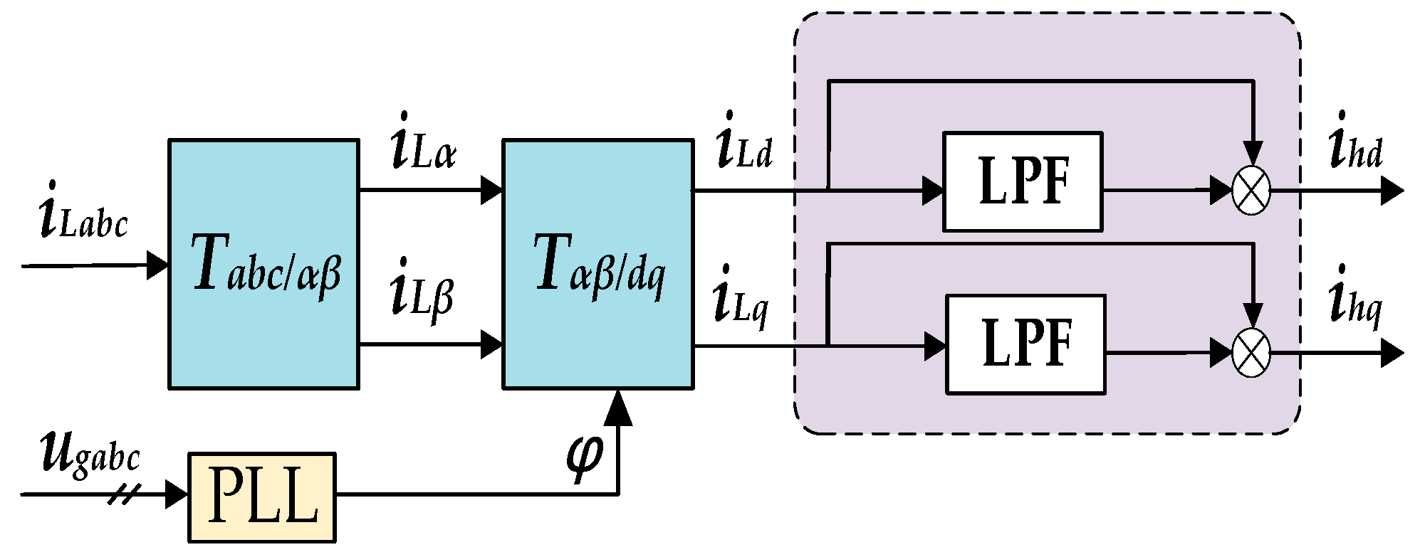
To enable power quality management for the multi-function grid-connected inverter, a power quality detection module is required. This module can accurately and quickly detect current harmonics and negative-sequence current components in microgrids. In Figure 4, for the Low-Pass Filter (LPF), this paper uses a moving average filter (MAF) to obtain the DC components ILdz and ILqz.
These DC components represent the fundamental positive sequence components of the load current in the three-phase abc stationary coordinate system, and the harmonic and negative-sequence current components needed for power quality management in the dq rotating coordinate system are calculated and shown as
i h d = i L d I L d z i h q = i L q I L q z
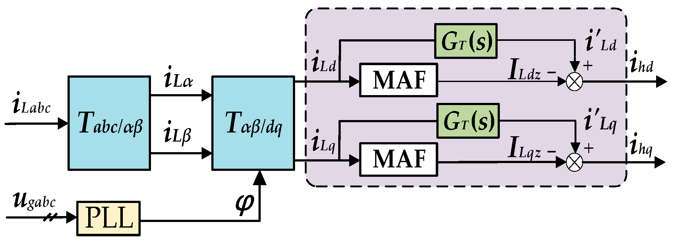
Based on (3), this paper uses the improved current detection module shown in Figure 5. By adding a delay link GT(s), it suppresses fluctuations of the inverter output current, because reference current changes are caused by the inherent delay of the moving average filter in the detection module. The improved method reduces transient fluctuations in the multi-function grid-connected inverter output current, which arise from the difference between iLd and ILdz at different times.
In Figure 3, the d-axis reference value isdref of the inner current loop in the improved control structure is composed of four parts and is
i s d r e f = i L d 0 + i c d + i g d + Δ I o d
where iLd0 is the control variable generated by the outer voltage controller, icd is the capacitor current, igd is the grid-connected current, and ∆Iod is the current compensation output by the outer power controller.
By introducing feed-forward of grid-connected current igd and capacitor current ic, these become part of the inner current loop reference value. During unplanned off-grid events, as igd suddenly drops to zero, the grid-connected current feed-forward component in isdref also becomes zero. This reduces isdref to match the actual induction current isd, minimizing isd oscillations.
In terms of the outer power loop, unlike traditional PQ control, an additional current controller and limiter are included to suppress oscillations in the inverter output current iod during unplanned off-grid events. The relationship among the output current iod, the load current iLd, and the grid-connected current iLd is as follows:
i o d = i L d + i g d
When unplanned off-grid transitions occur, switch ST2 is set to 1. Due to the detection of igd, the limiter is activated, and S1 closes. During off-grid detection, the sudden drop of igd to zero causes a sudden change in the inverter output current iod, leading to an abrupt change in the difference between iodref and iod. However, under the action of the limiter, the current regulator GI2 quickly saturates, limiting oscillations in the output current io. The relevant expressions are
Δ i o d = K p 1 + K i 1 s i o d r e f i o d Δ i o d l = α · Δ i o d i o d r e f = 2 3 · P r e f u o d
where ∆iod is the output value of the PI controller GI2 without the limiter and ∆iod_l is the output value of GI2 under the limiter action. iodref is the inverter output current reference calculated by the outer power loop, and Pref is the given reference value of the inverter output active power. uod denotes the inverter output voltage, and Kp1 and Ki1 are the proportional and integral coefficients of GI2, respectively. α is the limiter, with a value range of 0 < α < 1.
The final output of the power controller ∆Iod is
Δ I o d = Δ i o d Δ i o d l S T 2 = 0 S T 2 = 1
During off-grid detection, the modified current reference value isdref is derived from (3), (6), and (7), shown as follows:
i s d r e f = i L d 0 + i c d + i g d + Δ i o d l
Since igd = 0 during grid faults and the capacitor current icd of the LCL filter is much smaller than iLd0, (8) is simplified as
i s d r e f = i L d 0 + Δ i o d l
As shown in (9), by using a limiter to maintain ∆iod_l at a minimal value (approximately 0) while ensuring that the output of the composite harmonic voltage controller (iLd0 + iLdH) is approximately equal to the rated load current iLd, the reference value of the inner current controller could be made nearly equal to the actual value of the inductor current isd (iLd + icd). This reduces oscillations in the currents iod and isd, as well as in the main inverter’s output active power P, thereby mitigating voltage surges in the inverter output uoabc. This achieves a smooth unplanned off-grid transition. Furthermore, the QPR harmonic compensator mitigates the harmonic and negative-sequence components in the load current, improving the distortion of the main inverter’s output voltage uoabc after the loss of grid support and establishing a qualified AC bus voltage.

3.2. Composite Controller Combining PI and QPR

In the outer voltage controller, it is necessary to establish standard-compliant voltage amplitude and frequency during off-grid events. PI controllers cannot effectively track and control voltage harmonics or unbalanced components. In contrast, quasi-proportional resonant (QPR) controllers can track specific frequency harmonics. Therefore, the voltage controller uses a composite structure that combines PI and QPR controllers.
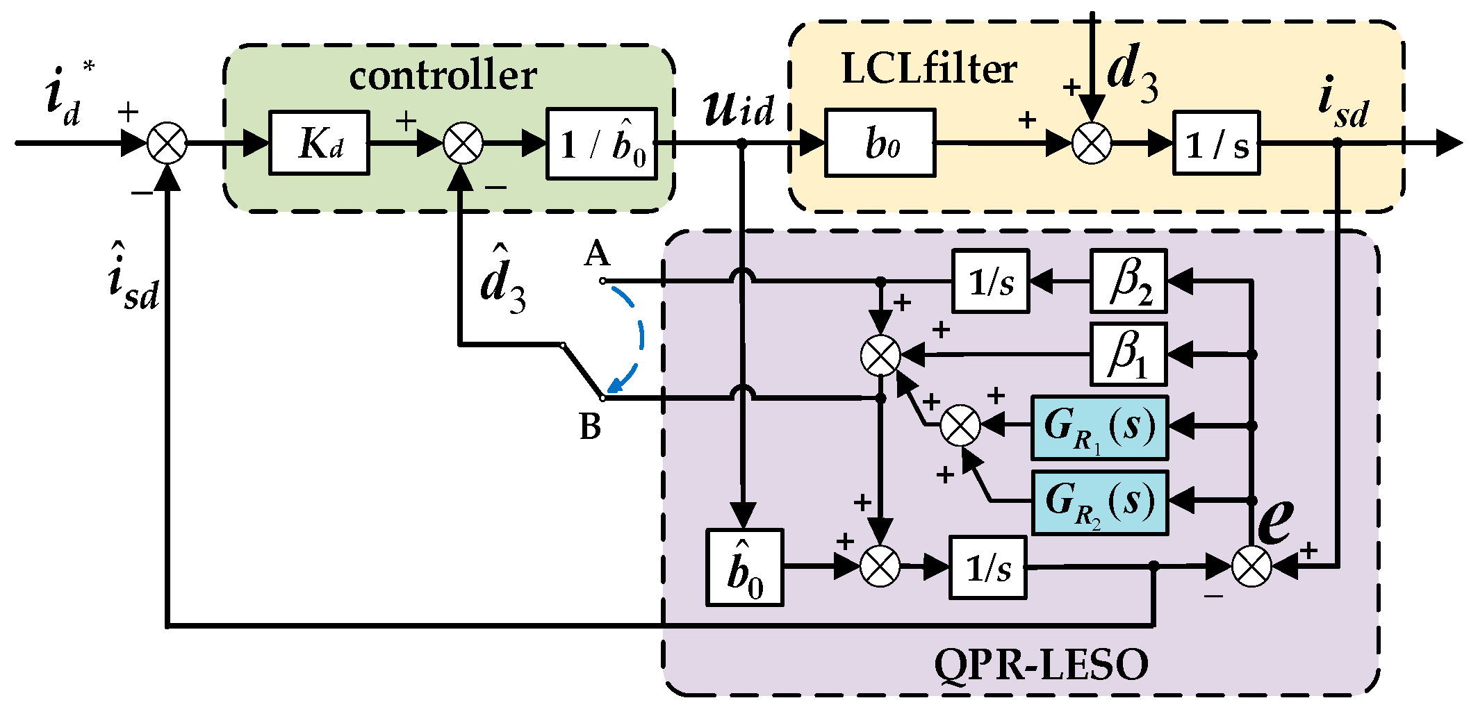
By integrating the QPR controller into the linear extended state observer (LESO), the LESO is upgraded to the QPR-LESO. This enhances the tracking accuracy of the inner linear active disturbance rejection current controller for harmonic and negative-sequence currents, improving the poor power quality caused by non-linear and unbalanced loads in microgrids. The structure diagram of the improved linear active disturbance rejection current controller based on the quasi-proportional resonant linear extended state observer (QPR-LADRC) is shown in Figure 6.
In Figure 6, GR1(s) and GR2(s) represent the transfer functions of the quasi-resonant controller, as shown in (10). Here, Kr1 and Kr2 are the controller gains, ωc1 and ωc2 are the controller bandwidths, and ωn1 and ωn2 are the controller resonance frequencies.
G R 1 ( s ) = 2 K r 1 ω c 1 s s 2 + 2 ω c 1 s + ω n 1 2 G R 2 ( s ) = 2 K r 2 ω c 2 s s 2 + 2 ω c 2 s + ω n 2 2
By setting the resonance frequencies ωn1 and ωn2, parallel quasi-resonant (QPR) controllers can track harmonic current AC signals at frequencies ωn1 and ωn2 without static error, thus guaranteeing that the system suppresses harmonic currents with angular frequencies ωn1 and ωn2. This improves the suppression of harmonics and negative-sequence components in the grid-connected current, enhancing the inverter power quality management capability. Specifically, it focuses on mitigating the fifth/seventh harmonics and negative-sequence components. In the dq coordinate system, only two QPR controllers with resonance frequencies 2ω0, where ω0 is the fundamental angular frequency, ω0 = 100π, and 6 ω0, are connected in parallel connections. Compared with the αβ stationary coordinate system, this method reduces the number of parallel QPR controllers and simplifies the control structure.
As shown in Figure 6, GR1(s), GR2(s), and β1 form a parallel quasi-proportional resonant (QPR) controller with the improved observer (QPR-LESO). The expression of the QPR-LESO is given as
i ^ ˙ s d = b 0 u i d + d ^ 3 d ^ ˙ 3 = β 1 + G R 1 ( s ) + G R 2 ( s ) e ˙ + β 2 e
The perturbation transfer function Gd3(s) of the system in the improved QPR-LADRC is obtained as shown as
G d 3 ( s ) = s s 2 + 2 ω e + G R 1 ( s ) + G R 2 ( s ) s + ω e 2 = s s 2 + 2 ω c 1 s + ω n 1 2 s 2 + 2 ω c 2 s + ω n 2 2 s 2 + 2 ω c 1 s + ω n 1 2 s 2 + 2 ω e s + ω e 2 s 2 + 2 ω c 2 s + ω n 2 2 + 2 ω c 2 K r 2 s 2 + s 2 + 2 ω c 2 s + ω n 2 2 2 ω c 1 K r 1 s 2
Meanwhile, a mode switcher ST3 is set to meet the operation mode requirements of multiple working states. When ST3 = 1, the inverter operates in off-grid mode, aiming to control the inverter output voltage uod to the rated reference voltage uodref. The control variable generated by the voltage controller is iLd0, whose steady-state value equals the actual load current iLd in off-grid mode. When ST3 = 0, the inverter operates in grid-connected mode under current-controlled mode. The input of the PI-QPR composite controller GVPIPR is zero, the output iLd0 equals the load current iLd, and the voltage controller acts as a voltage regulator to maintain consistency between the inverter output voltage and grid voltage. The expression of the outer voltage control variable iLd0(t) is
i L d 0 ( t ) = i L d 0 ( t 1 ) S T 3 = 0 u o d r e f u o d G V P I P R S T 3 = 1
where iLd0(t) and iLd0(t − 1) denote the actual outputs of the voltage controller at t and t − 1 (the previous moment), respectively.
Combining (12) and (13), the inner current loop controller reference value isderf is obtained and shown as
i s d r e f = i L d + Δ i o d l
where ∆iod_l is approximately equal to 0 and isderf matches the actual load current, which reduces the inverter output voltage and power oscillations, thus smoothing the unplanned off-grid transition.

4. Analysis of Operating Modes

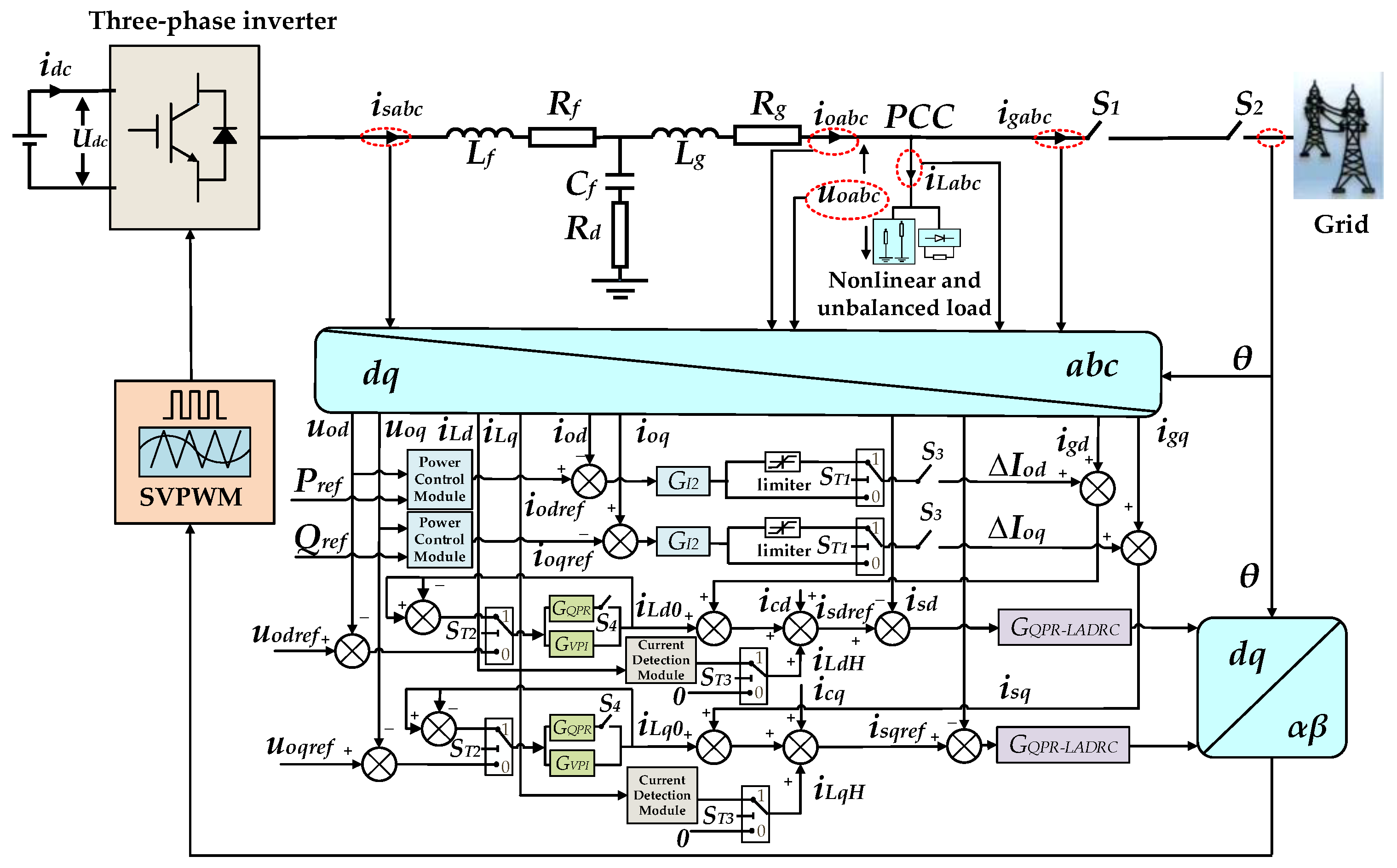
The control strategy for the multi-function grid-connected inverter in the dq rotating coordinate system is shown in Figure 7. This control strategy enables multi-mode operation and allows for the smooth switching between operating modes according to actual needs. Five operating modes are defined as follows: grid-connected mode, off-grid mode, planned off-grid-to-grid-connected transition, planned grid-connected-to-off-grid transition, and unplanned grid-connected-to-off-grid transition. These modes are primarily determined by switch states.
(1) In off-grid mode, the objective is to regulate the amplitude and frequency of the AC bus voltage to establish a qualified voltage level. In Figure 7, both switches S1 and S2 are open, resulting in zero grid-connected current igd. Meanwhile, the outer loop S3 of the power controller is disconnected. At this time, ST2 = 0 causes the current controller and limiter of the outer power loop to disengage. Based on the control structure of the multi-functional inverter shown in Figure 7, the simplified diagram in off-grid mode is derived and illustrated in Figure 8.
The control variable of the outer voltage loop PI-QPR composite controller is iLd0. Neglecting the effect of the capacitor current, the control variable iLd0 serves as the reference value isdref for the inner current loop. Thus, the magnitude of iLd0 equals the actual load current iLd0 in off-grid mode. The PI-PR composite controller compensates for harmonic and unbalanced voltage components, regulating the AC bus voltage to the rated value while ensuring that the voltage THD complies with power consumption standards.
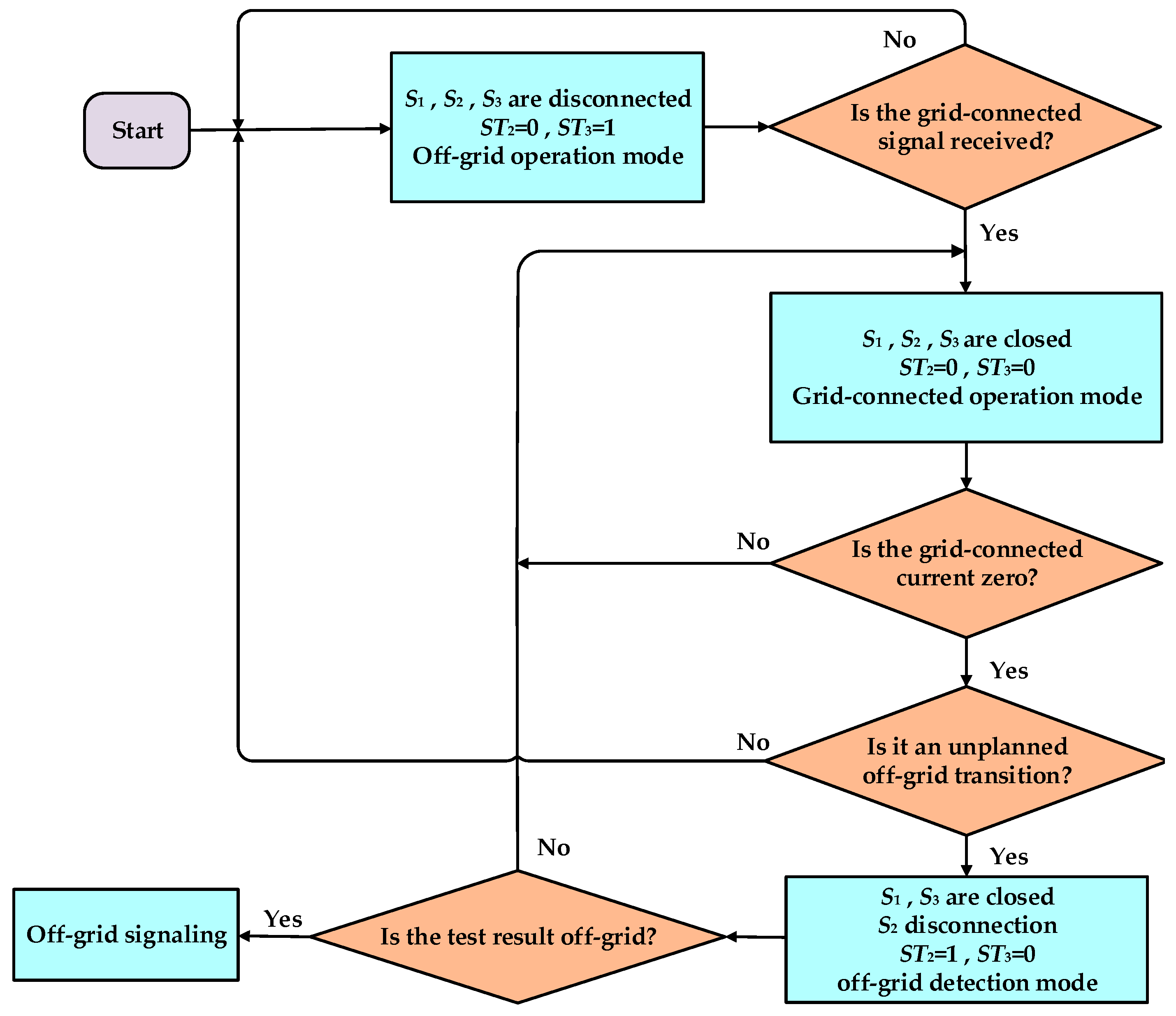
(2) During planned switching from off-grid mode to grid-connected mode, the inverter firstly initiates pre-synchronization control before sending a grid-connection signal. At this point, both S1 and S2 are closed to start the planned grid connection. After successful grid integration, the outer loop S3 of the power controller closes. With ST2 = 0, the current controller of the power loop is activated (without engaging the limiter), while ST3 = 0 in the outer voltage loop. In this state, the outer voltage loop no longer controls the AC bus voltage (which is now supported by the grid), and the inverter output power is regulated by the power outer loop.
(3) In grid-connected mode, the inverter supplies power to both loads and grid simultaneously. In this mode, the switches are in the following states: S1 and S2 are both closed, and S3 is closed, with ST2 = 0 and ST3 = 0. Figure 9 shows the simplified block diagram of the multi-functional inverter in grid-connected mode, derived from Figure 7. ∆iod_l is the output of GI2 in the outer power loop controller.
Reference GI2 compensates for real-time fluctuations in the grid-connected current Igd, enhancing the inverter disturbance rejection capability. The control variable iLd0 remains unchanged and is no longer controlled by the outer voltage controller. iLdH represents the harmonic and negative-sequence current components extracted by the power detection module. At this time, the reference value of the current inner loop is
i s d r e f = i L d 0 + i g d + Δ I o d + i L d H
Based on (15), the reference of the inner current loop is independent with the voltage outer loop. Thus, the multi-functional inverter operates in current-controlled mode in grid-connected modes. Its output power is determined by the active power reference Pref and reactive power reference Qref from the outer power loop. The inner current loop reference value includes both the fundamental active power component and harmonic/negative-sequence current components. Thus, the inner current loop could effectively track the given current reference. This guarantees that the multi-functional inverter not only generates grid-connected power but also locally mitigates harmonic currents and negative-sequence currents caused by non-linear and three-phase unbalanced loads in microgrids.
(4) During unplanned switching from grid-connected mode to off-grid mode, the multi-functional inverter remains in grid-connected state before disconnection (with S1, S2, and S3 closed, and ST2 = 0 and ST3 = 0). Grid failure causes S2 to be open, losing grid support for AC bus voltage uPCC. This triggers off-grid detection (S1 and S3 are closed, ST3 = 0, ST2 = 1, and the limiter is activated). Figure 10 shows the simplified control structure of the multi-functional inverter during off-grid detection, derived from Figure 7. When ∆iod_l is about 0, isderf matches iLd in magnitude, reducing output voltage and power oscillations to achieve smooth unplanned off-grid transitions.
(5) For planned switching from grid-connected mode to off-grid mode, the difference from unplanned switching lies in the manual configuration of the S1 and S2 switch states, eliminating the need for off-grid detection. Before off-grid transition, S1 and S2 are both closed, and during planned disconnection, S1 and S2 are opened simultaneously. Upon receiving the disconnection signals, the control system opens S3, sets ST2 = 0, and activates ST3 = 1, switching the multi-functional inverter from grid-connected mode to off-grid mode. Based on the switch states, a multi-modal operation flowchart of the multi-functional inverter is shown in Figure 11. Under non-linear and unbalanced loads, the inverter controls the AC bus voltage via an outer PI-QPR voltage controller and an inner current controller in off-grid mode. In grid-connected mode, the PI-QPR voltage controller acts as a load voltage regulator with outputs consistent with off-grid mode. It works in conjunction with grid-connected current feed-forward, an improved outer loop of the power controller, a power quality detection module, and an inner current loop. Together, these components adjust grid-connected current, enhance power quality, and ensure that the output of the PI-QPR voltage controller matches the load current during off-grid detection for unplanned off-grid transition, thus maintaining stable, qualified voltage.

5. Simulation and Experimental Results

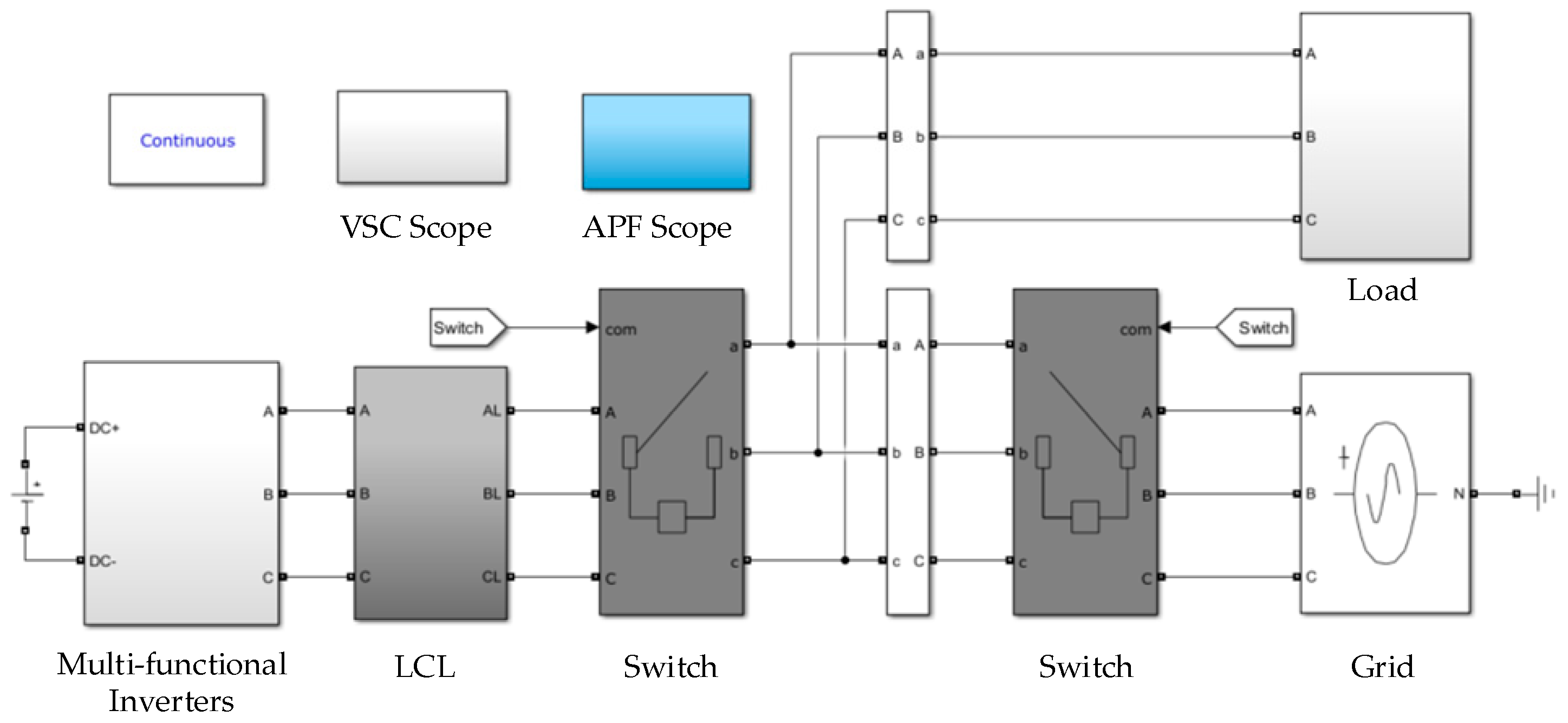
To verify the effectiveness and feasibility of the proposed smooth droop control strategy for multi-functional inverters, a simulation model was established using MATLAB/Simulink 2024a based on Figure 7, as shown in Figure 12. The simulation parameters of the multi-functional inverter are listed in Table 1. Firstly, simulations of planned off-grid-to-grid-connected and unplanned grid-connected-to-off-grid switching were conducted using traditional control strategies. Then, the same conditions from off-grid mode to grid-connected mode were implemented with the proposed strategy.

5.1. Simulations of Full-Mode Operation of Conventional Switching Strategy for Inverters

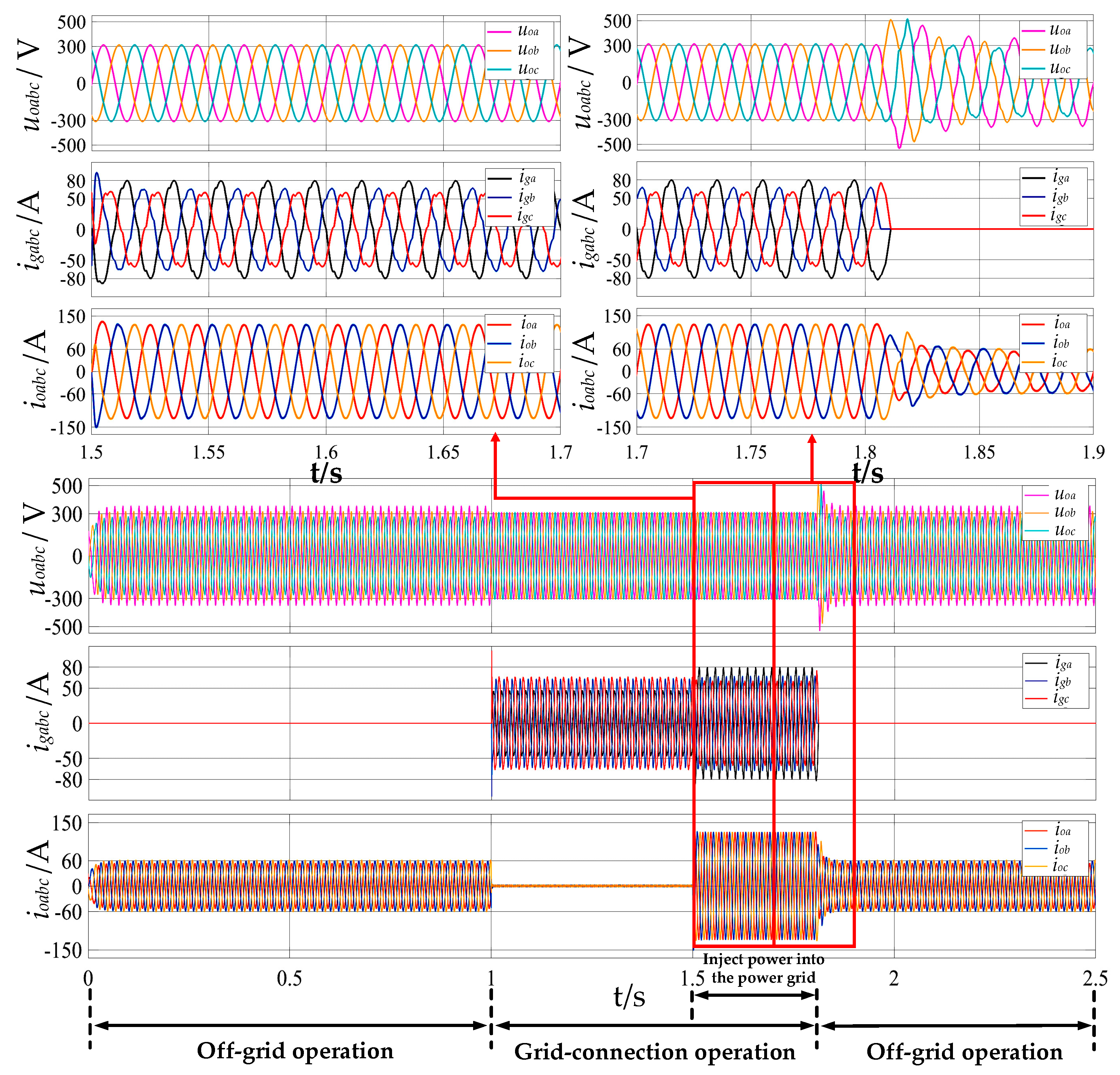
When the traditional PQ/VF control-switching method is adopted, the inverter operates in off-grid mode from t = 0 s to 1 s. During this period, synchronization control is initiated, and the amplitude and phase of the inverter output voltage rapidly synchronize. At t = 1 s, shock-free smooth grid connection is achieved. The inverter then operates in grid-connected mode from t = 1 s to 1.8 s. The simulation results are shown in Figure 13.
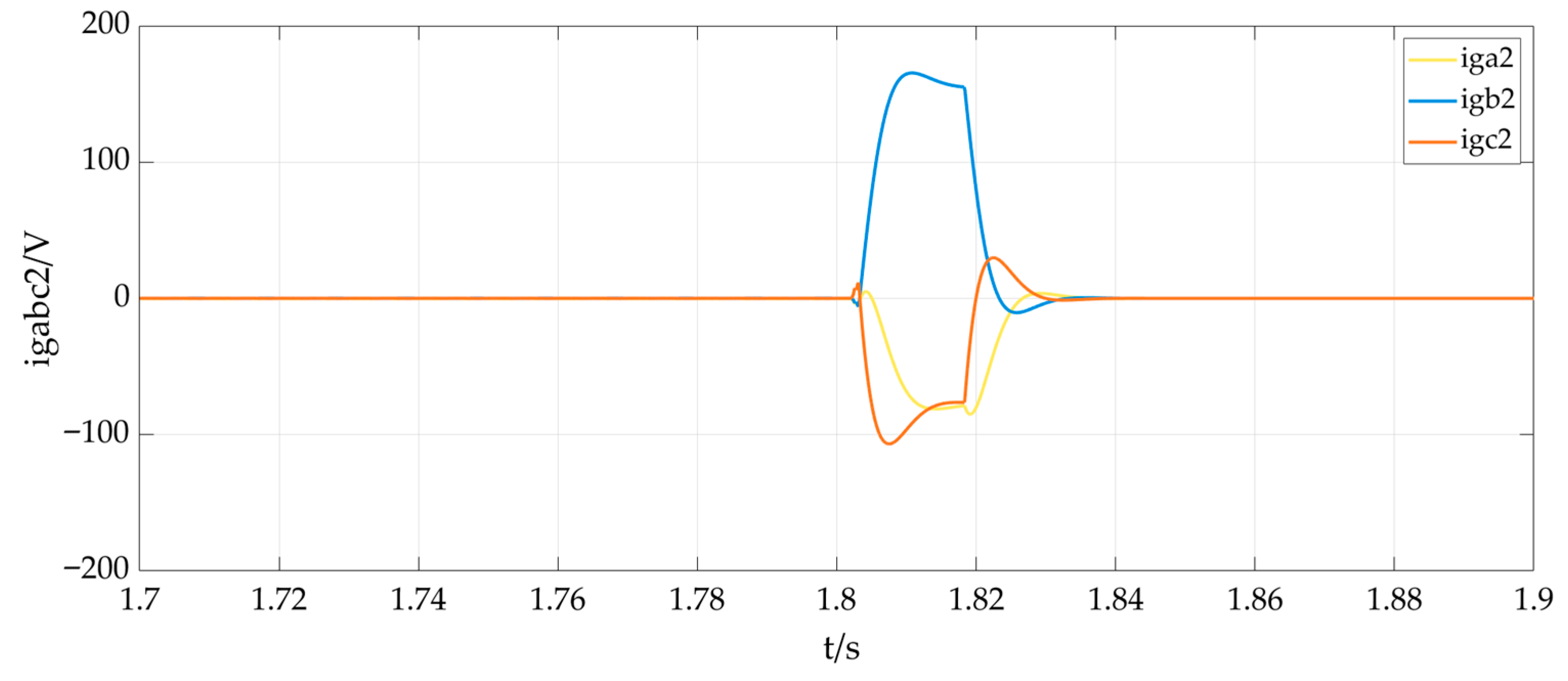
As shown in Figure 13, when a grid fault occurs at t = 1.8 s, the controllable protection switch S2 is directly opened, and the inverter changes to off-grid mode. However, due to off-grid detection by the controller, the inverter remains in grid-connected mode (current control mode) during off-grid detection. As presented in the enlarged view of Figure 13, when the traditional switching strategy is employed, the single-phase peak value of the inverter output voltage uoabc exhibits a sudden increase during the off-grid detection process. Specifically, the peak voltage surges from 311 V to over 500 V, corresponding to an overshoot of approximately 60.8% and a settling time of 1.815 s. This is because the inverter output voltage uoabc loses grid support and becomes uncontrollable and fully directed to the loads. After off-grid detection is completed, the inverter-side switch S1 is opened, and the grid-connected inverter switches from PQ control to grid-forming control. After the control switching is completed, the inverter output voltage uoabc tends to return to normal. Additionally, due to the influence of non-linear and unbalanced loads, the inverter output current and grid connection point voltage exhibit severe distortions, and three-phase imbalances emerge during off-grid detection and in off-grid mode. As shown in Figure 14, at the moment of switching at 1.8 s, the generated three-phase unbalanced negative-sequence current reaches a maximum of nearly 180 A. This will cause a great impact on the power grid and affect the stable operation of the power grid. Consequently, voltage quality fails to meet national standards.

5.2. Simulations of Full-Mode Operation of the Inverter with Proposed Multi-Modal Control Strategy

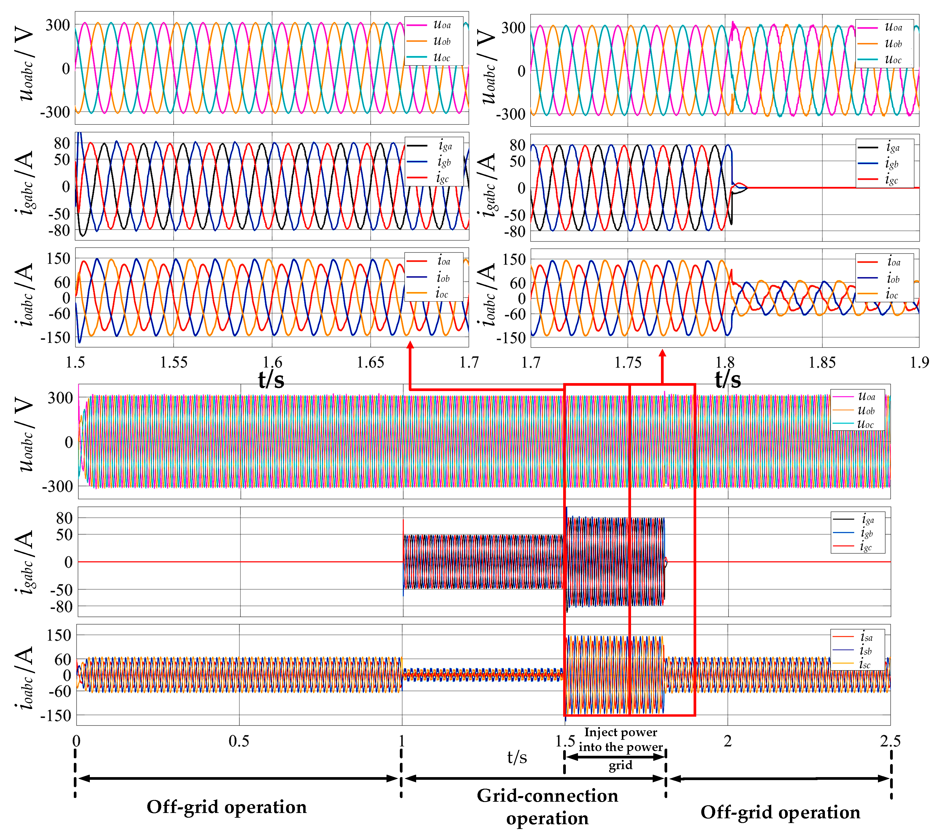
Figure 15 shows the full-mode operation simulation results of the proposed multi-modal control strategy. From t = 0 s to 1 s, the grid-connected inverter is in off-grid mode, and synchronization control is activated to rapidly synchronize the amplitude and phase of the inverter output voltage. At t = 1 s, shock-free smooth grid connection is achieved, and the inverter operates in grid-connected mode from t = 1 s to 1.8 s.
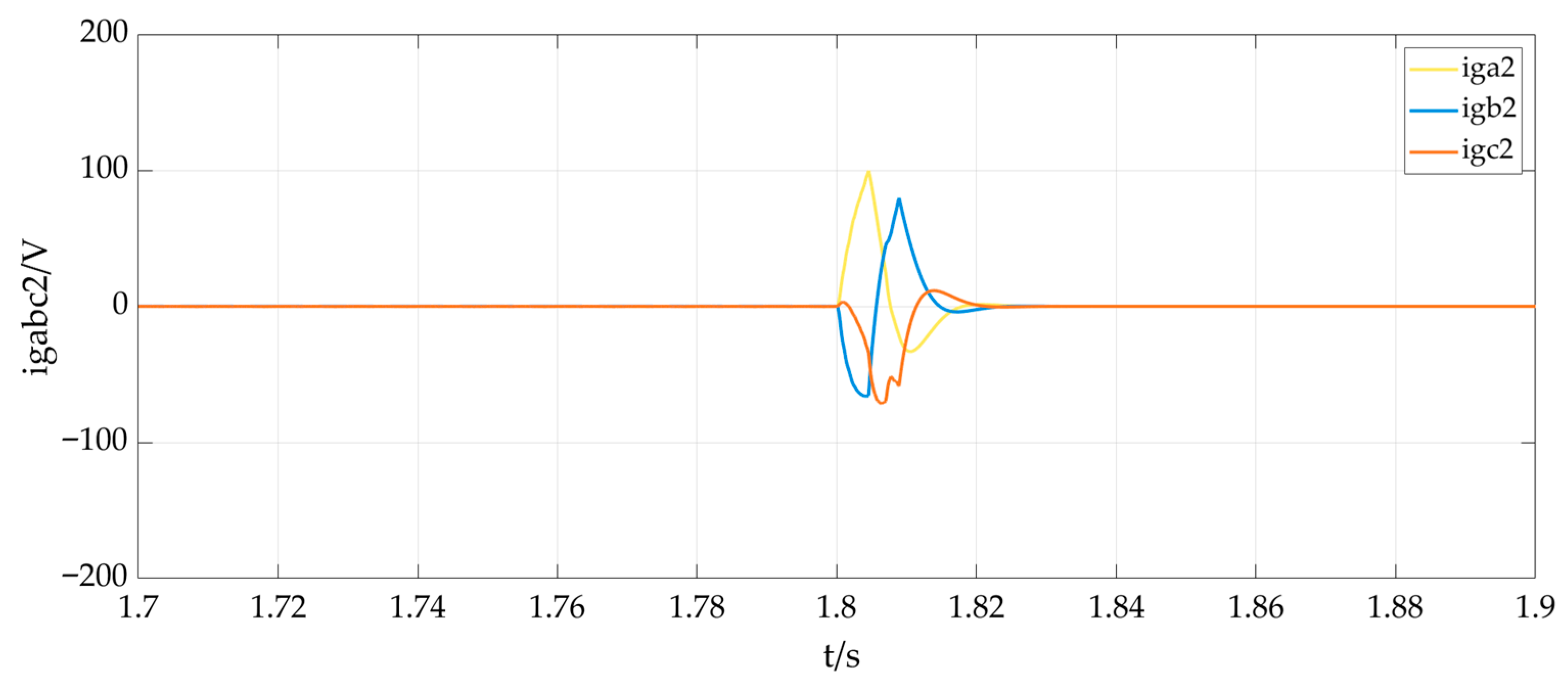
As shown in Figure 15, when a grid fault occurs, the multi-modal control strategy ensures that the inverter output voltage uoabc remains nearly unchanged during the unplanned off-grid process, and single-phase voltage rises from 311 V to approximately 326 V, where the settling time is 1.809 s. Compared with the phase A voltage surge from 311 V to over 500 V in Figure 13, the proposed strategy significantly reduces the overshoot of uoabc during unplanned off-grid transitions. This is because during off-grid detection, the improved composite harmonic voltage controller acts as a load voltage stabilizer, with its control quantity being set to the rated load current value. Through coordination of the composite harmonic voltage controller, power outer loop, and grid-connected current feed-forward igd, the current inner loop reference isdref matches the actual load current, minimizing output voltage and power oscillations to achieve smooth, seamless unplanned off-grid transitions. As shown in Figure 16, when the converter adopting the proposed control strategy switches, compared with the traditional control strategy shown in Figure 14, the generated three-phase unbalanced negative-sequence current is reduced to within 100 A. This reduces the impact on the power grid caused by mode switching and is beneficial to the stable operation of the power grid.
Comparing Figure 13 with Figure 15, the derived multi-modal control strategy enables the inverter to deliver active power to the grid in grid-connected mode while also improving the power quality of the grid-connected current igabc. As shown in Figure 15, no distortions or three-phase imbalances occur in the current igabc.
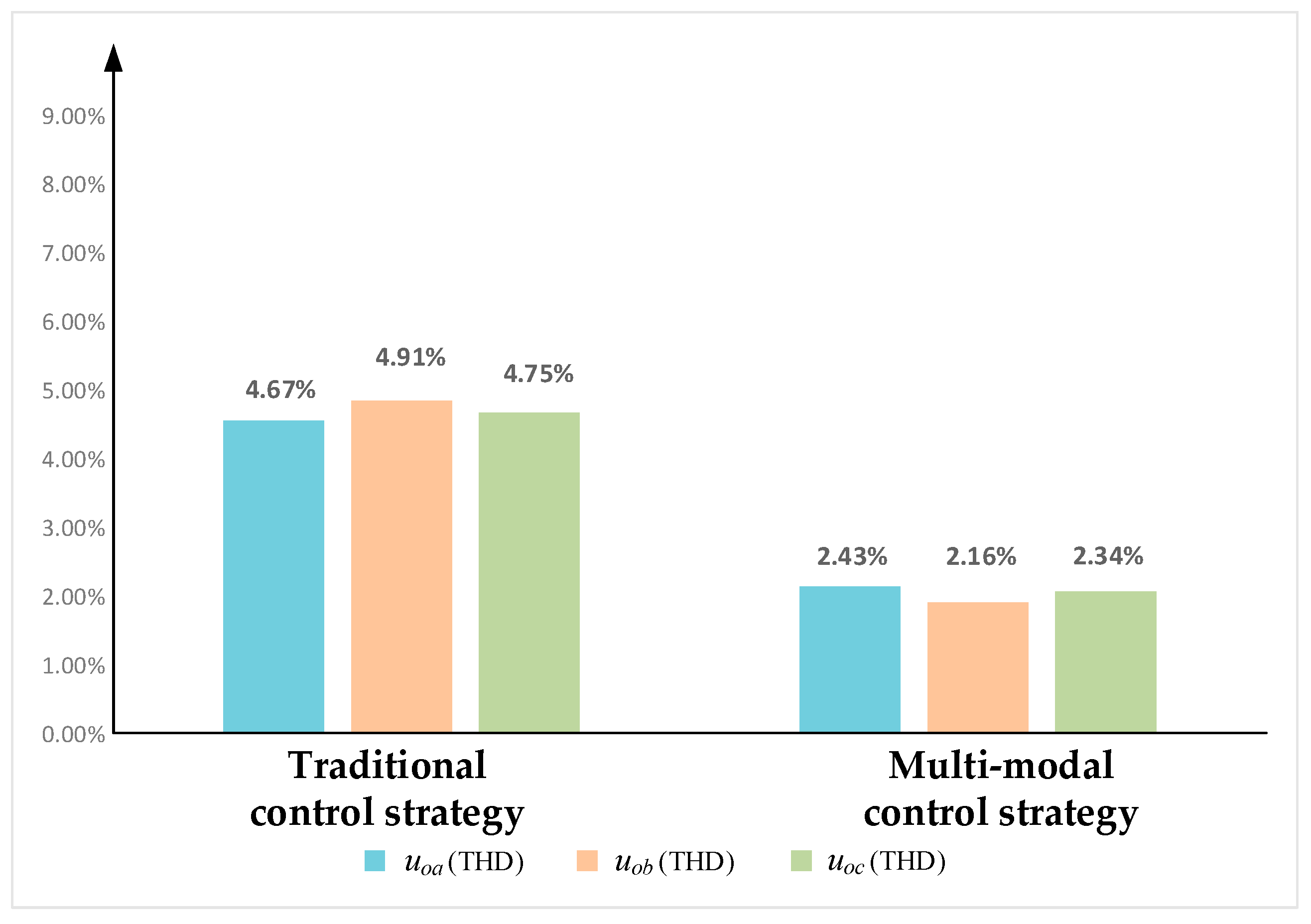
As shown in Figure 17, in off-grid mode, the measured results of the total harmonic distortion (THD) for each phase voltage of the inverter output voltages uoa, uob, and uoc under the traditional control strategy and the multi-modal control strategy in the simulation experiments are compared. The results show that under the traditional control strategy, the THD values of voltages uoa, uob, and uoc are 4.67%, 4.91%, and 4.75%, respectively. After adopting the multi-modal control strategy, the THD values of the inverter output voltages uoa, uob, and uoc are significantly reduced to 2.43%, 2.16%, and 2.34%, respectively.
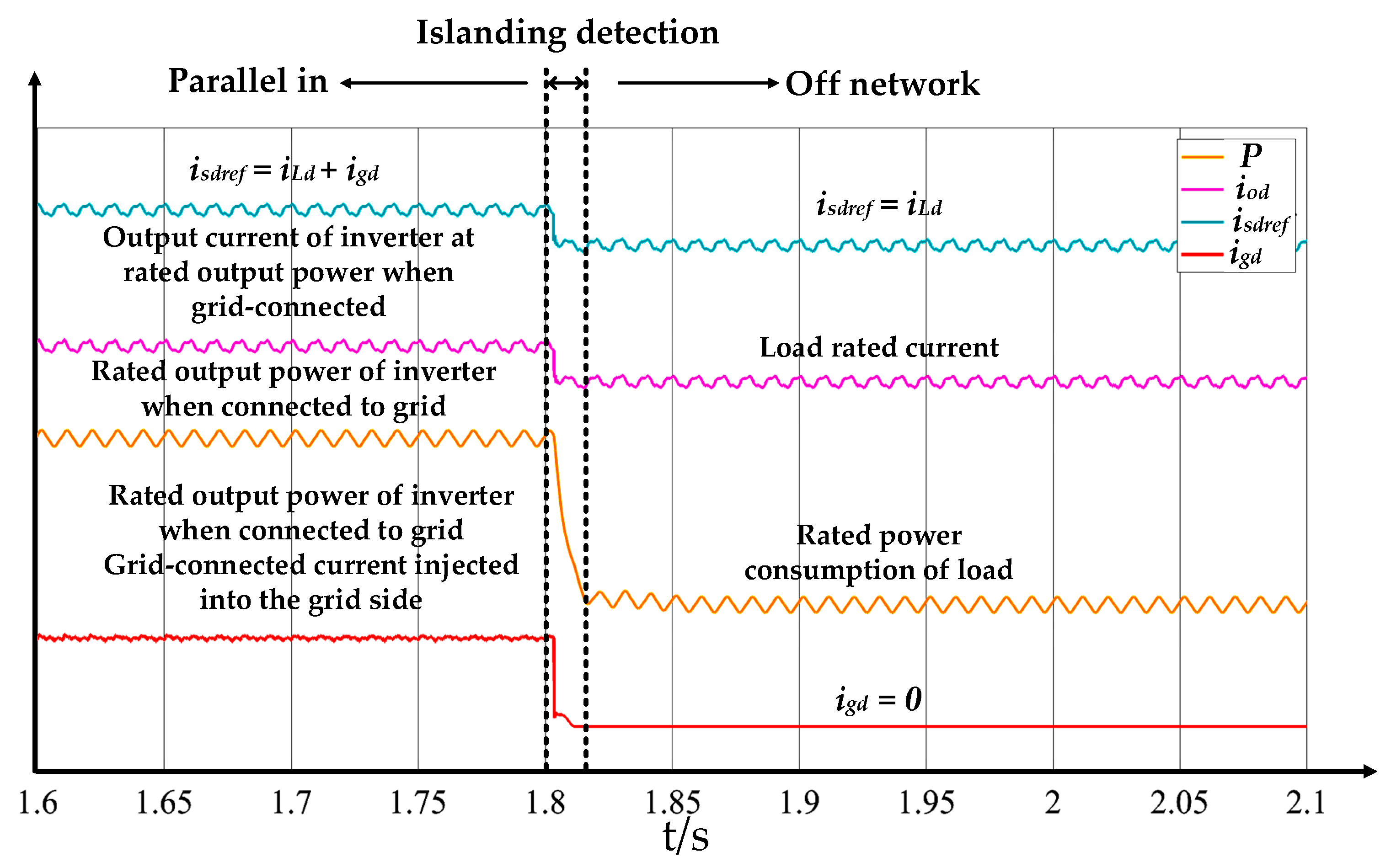
Figure 18 shows the electrical quantity changes in the dq coordinate system during unplanned off-grid transitions with the multi-modal control strategy. Taking the d-axis component as an example, the figure indicates that no sudden changes occur in the inverter inductor current reference isdref or output power P during off-grid detection, and the multi-functional inverter output voltage uoabc exhibits no overshoots.
The simulation results from Figure 13, Figure 14, Figure 15, Figure 16, Figure 17 and Figure 18 demonstrate that the proposed multi-modal control strategy for the inverter achieves smooth and seamless operation during different mode transitions. It significantly reduces output voltage overshoots during unplanned off-grid transitions and mitigates voltage distortions and three-phase imbalances under off-grid conditions.

6. Experiments

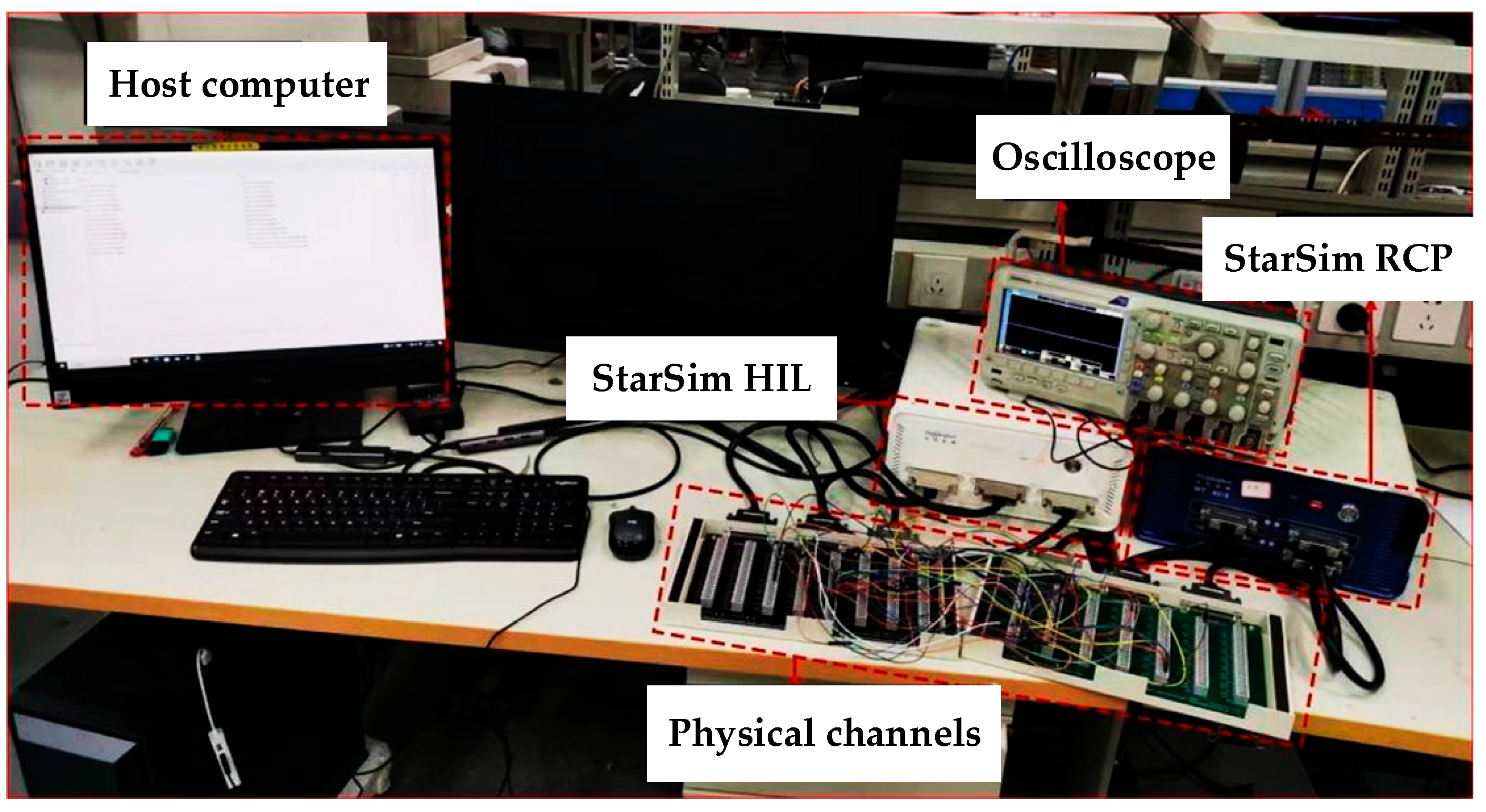
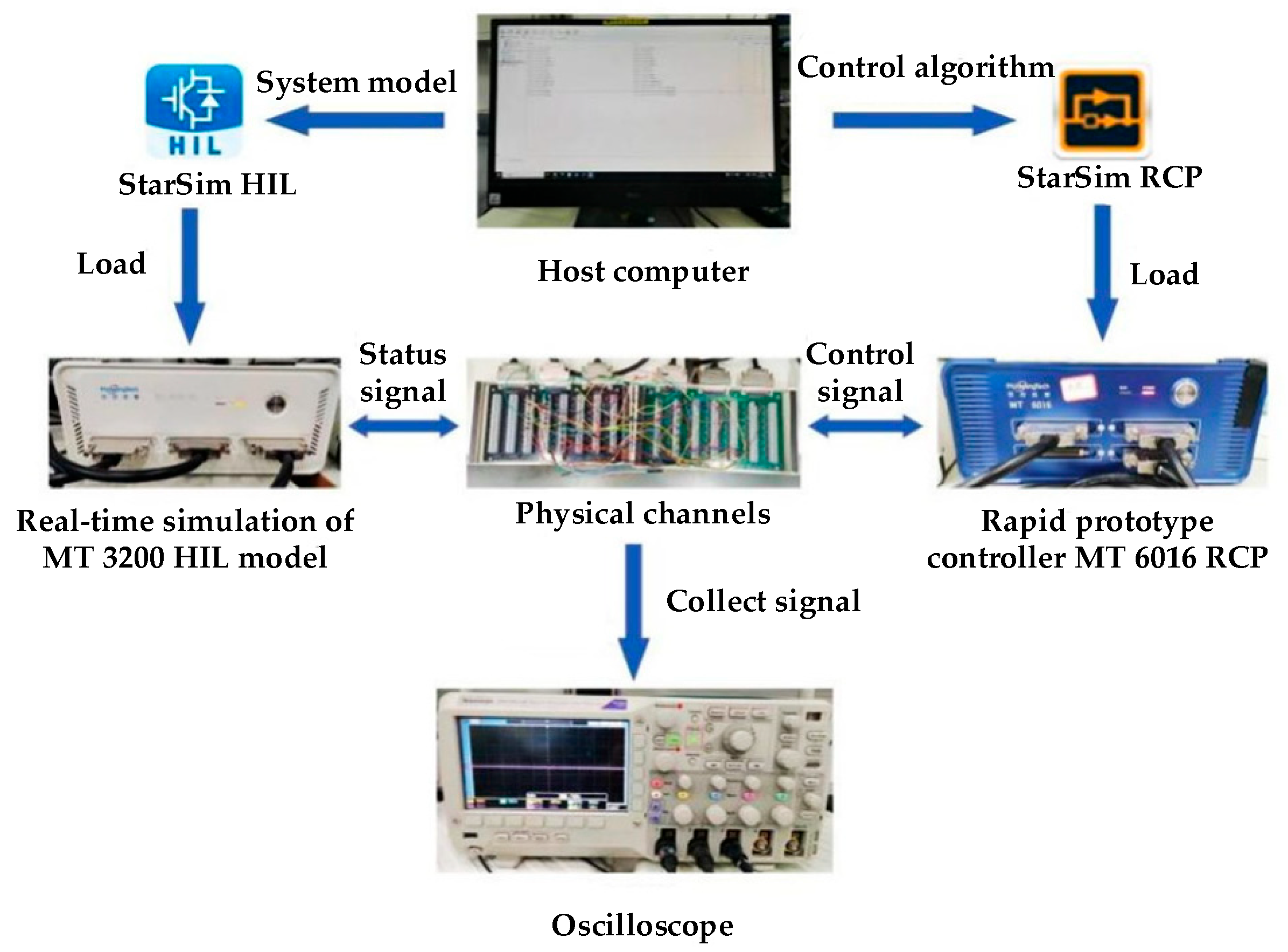
To validate the effectiveness of the proposed multi-modal control strategy for the inverter, a test system was built on the YuanKuan Hardware-In-the-Loop (HIL) experimental platform, based on the topology and control strategy of the multi-functional inverter shown in Figure 7. As shown in Figure 19, the HIL experimental platform mainly consists of a StarSim MT3200 HIL (real-time simulator), a StarSim MT6016 (rapid control prototyping, RCP) controller, physical channels, an oscilloscope, and a host computer, and its working principle is illustrated in Figure 20. StarSim MT3200 HIL and StarSim MT6016 are manufactured by Yuan Kuan Energy, Shanghai, China. Since the HIL platform uses actual electrical signals for sampling, signal generation, and internal signal interactions, its experimental results are widely recognized in the power electronics industry. The specific parameters for the multi-functional inverter HIL platform experiments are consistent with the simulation parameters listed in Table 1. The experiments firstly verified the multi-functional inverter power quality under off-grid conditions with unbalanced and non-linear loads; then planned off-grid-to-grid-connected switching is verified. Finally, smooth unplanned grid-connected-to-off-grid switching is validated.

6.1. Experimental Verifications of Switching from Off-Grid Mode to Grid-Connected Mode of Multi-Functional Inverter

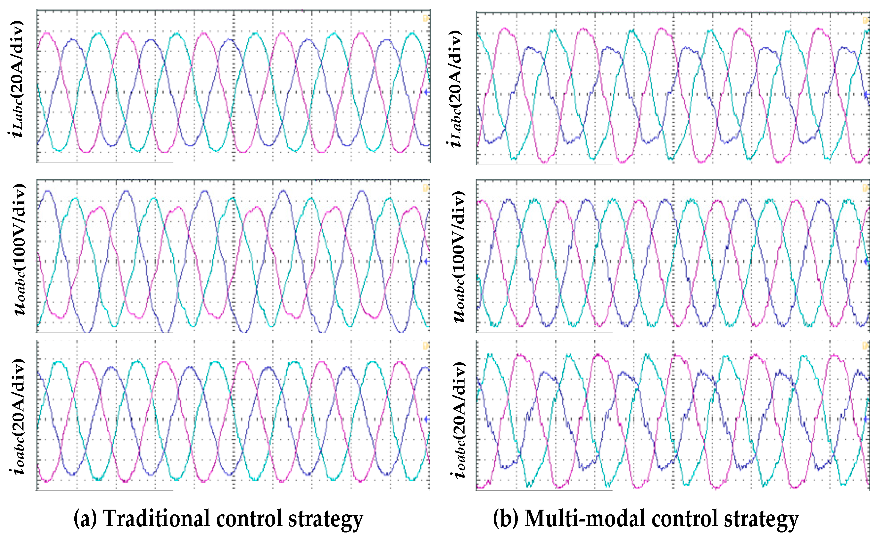
To verify the smooth switching from off-grid mode to grid-connected mode of the multi-functional inverter, comparative experiments were set up with the traditional strategy and the proposed multi-modal control strategy, as shown in Figure 21. Specifically, Figure 21a,b present the experimental waveforms of load current iLabc, grid-connected inverter output voltage uoabc, and output current ioabc. These waves correspond to the traditional grid-forming control strategy and the multi-modal control strategy, respectively.
The control objective of the inverter in off-grid mode is to maintain qualified voltages. As shown in Figure 21a, the inverter using the traditional grid-forming control strategy in off-grid mode has deficiencies in handling non-linear and unbalanced loads. The output voltage uoabc of the inverter exhibits obvious voltage distortions, including voltage harmonics and three-phase imbalances, resulting in poor voltage quality that fails to meet load power supply standards. This is mainly because the load current iLabc generated by non-linear and unbalanced loads contains a large number of harmonic and negative-sequence components, causing distortions in the inverter output voltage uoabc. Therefore, in off-grid mode, inverters using traditional control strategies have significant limitations in operating with non-linear and unbalanced loads, failing to meet load power requirements.
According to Figure 21b, the inverter adopting the proposed multi-modal control strategy in off-grid mode demonstrates a significant improvement in handling non-linear and unbalanced loads. The waveform of the inverter output voltage uoabc shows no obvious harmonic or negative-sequence voltage components and is a sinusoidal voltage waveform. Compared with the voltage waveform uoabc in Figure 21a, the power quality of the voltage is significantly enhanced. The experimental waves under the two control strategies in Figure 21 align well with the simulation waves in Figure 13 and Figure 15.
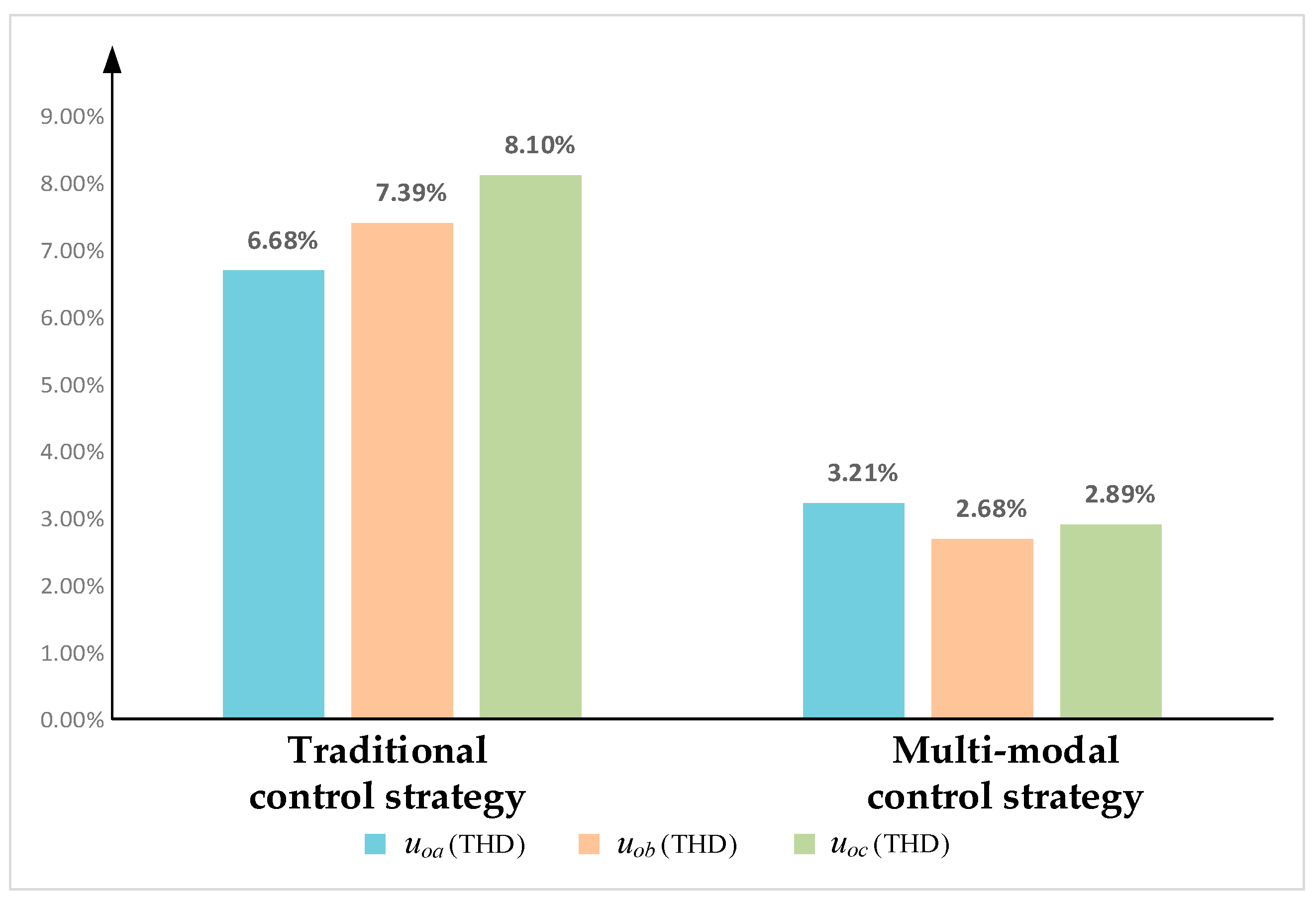
As shown in Figure 22, in off-grid mode, the measured results of the total harmonic distortion (THD) for each phase voltage of the inverter output voltage uoabc under the traditional control strategy and the multi-modal control strategy are compared. The results show that under the traditional control strategy, the THD values of voltages uoa, uob, and uoc are 6.68%, 7.39%, and 8.10%, respectively. After adopting the multi-modal control strategy, the THD values of the inverter output voltages uoa, uob, and uoc are significantly reduced to 3.21%, 2.68%, and 2.89%, respectively.
The experimental results verify the effectiveness of the improved composite harmonic voltage controller for suppressing voltage harmonics and negative-sequence components, thereby enhancing the multi-functional inverter performance in handling non-linear and unbalanced loads in off-grid mode.
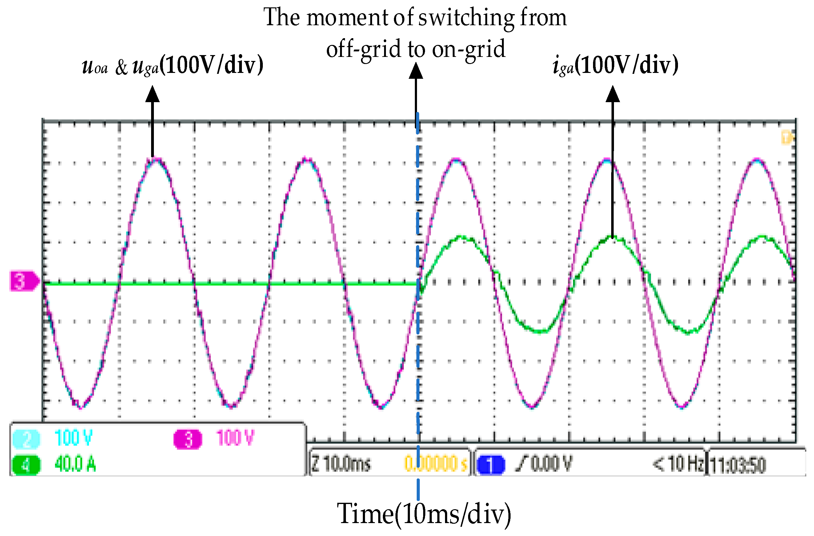
The experimental waves of smooth switching from off-grid mode to grid-connected mode are shown in Figure 23. Taking phase A as an example, the amplitude and phase of the inverter output voltage uoa rapidly synchronize with the grid voltage uga under synchronization control until they fully match grid voltage amplitude and phase, and smooth grid connection is prepared. At the moment of grid connection, since the inverter output voltage and grid voltage are completely consistent in amplitude and phase, the grid-connected inverter achieves shock-free, smooth synchronization. The experimental results verify the effectiveness of the synchronization control technology in the multi-modal control strategy.

6.2. Experimental Verifications of Smooth Unplanned Transition from Grid-Connected Mode to Off-Grid Mode for Multi-Functional Inverter

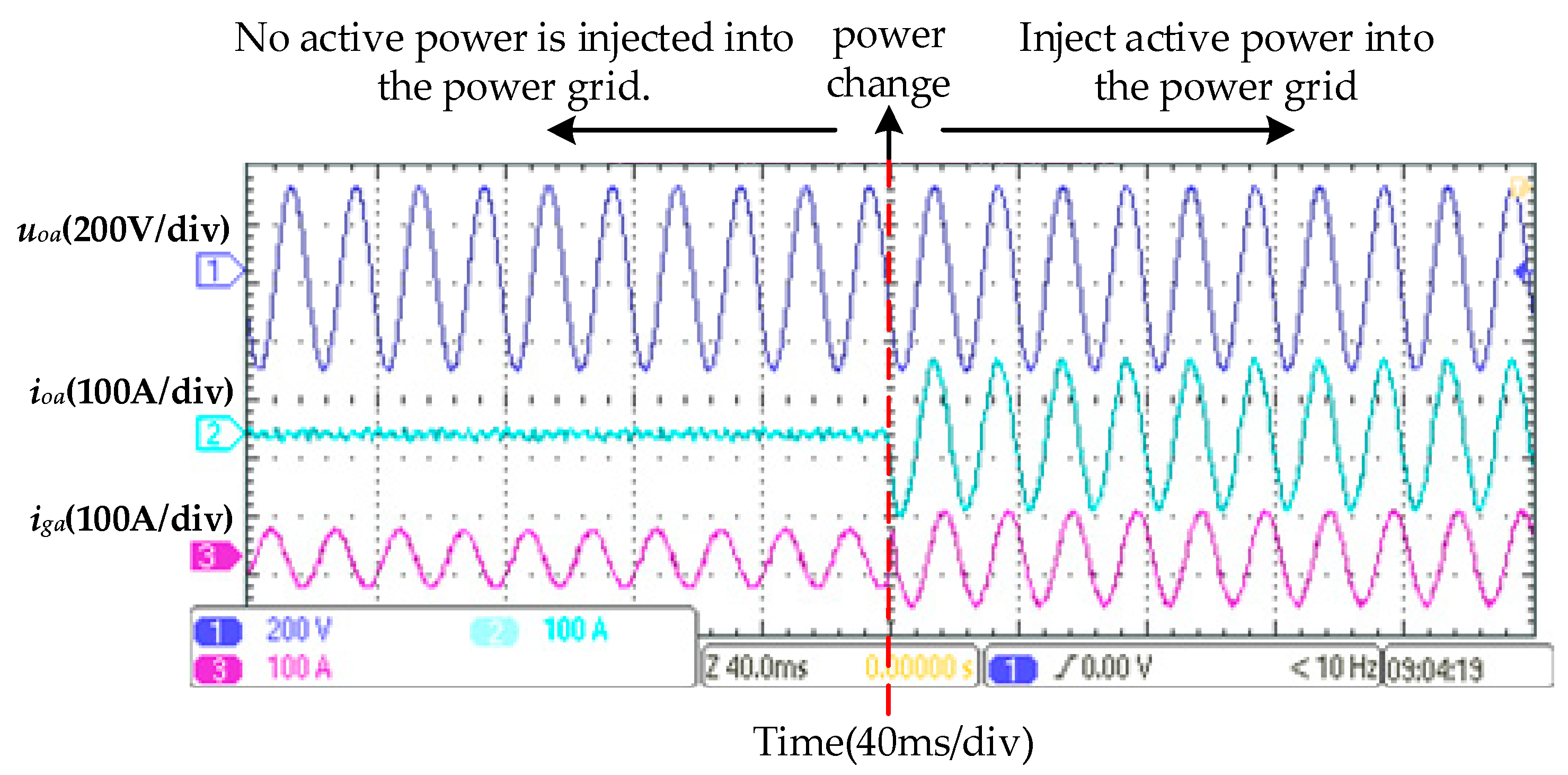
Firstly, the experiment verified that the multi-modal control strategy enables the inverter output power to track the grid-connected active power (injecting active power into the grid) in grid-connected mode, as shown in Figure 24. The figure displays the experimental waves of multi-functional inverter active power injection into the grid; uoa is the phase A output voltage, ioa is the phase A output current, and iga is the phase A grid-connected current in grid-connected mode. When the inverter does not inject active power into the grid (the grid-connected power is 0 kW), the inverter output current is very small, and it only performs on-site power quality conditioning for the power quality issues caused by non-linear and unbalanced loads near the PCC, with the grid supplying power to the loads. After the grid-connected power increases from 0 kW to 30 kW, the inverter not only supplies power to the loads and injects active power into the grid but also utilizes its remaining capacity to conduct on-site power quality conditioning at the PCC, improving the power quality of the grid-connected current. The experimental results in Figure 24 demonstrate that the inverter output power can track changes in grid-connected active power.
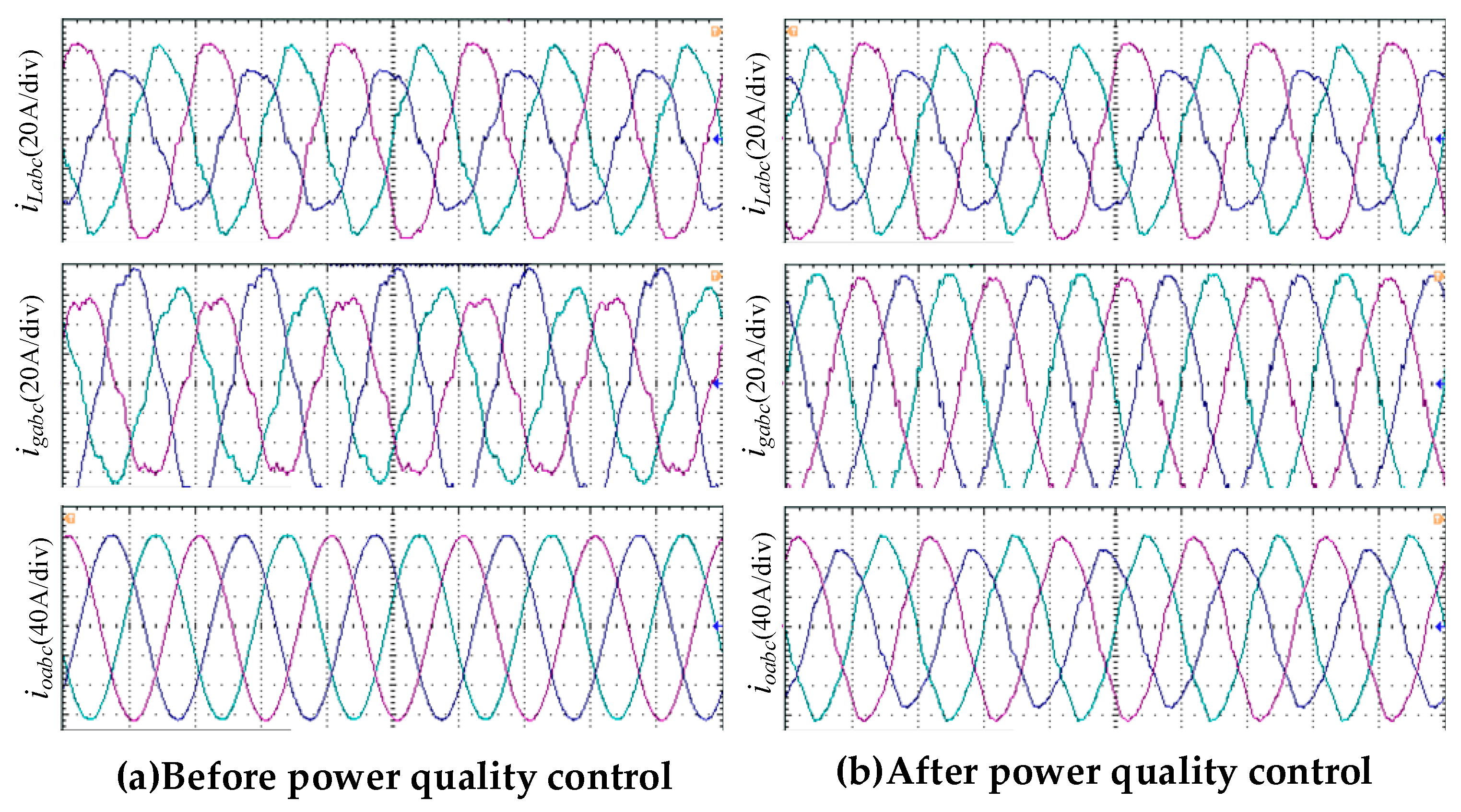
In order to further verify whether the multi-functional inverter can achieve grid-connected power generation and power quality governance functions in grid-connected mode, Figure 25 presents comparative experimental waveforms of load current ilabc, grid-connected current igabc, and inverter output current ioabc before and after power quality conditioning.
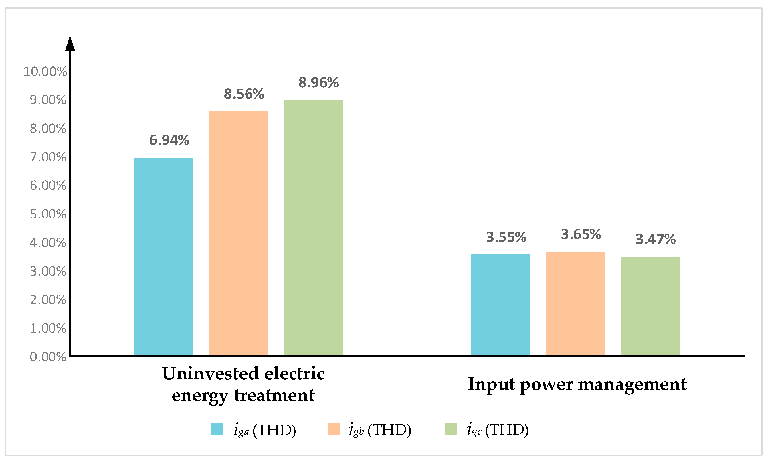
Figure 26 presents the THD measurement results of grid-connected current igabc for the multi-functional inverter in grid-connected mode. Based on Figure 25 and Figure 26, the proposed multi-modal control strategy enables the inverter to simultaneously achieve grid-connected power generation and address power quality issues from non-linear/unbalanced loads. The strategy ensures that the total harmonic distortion (THD) of grid-connected current remains below 5%, complying with national grid connection standards.
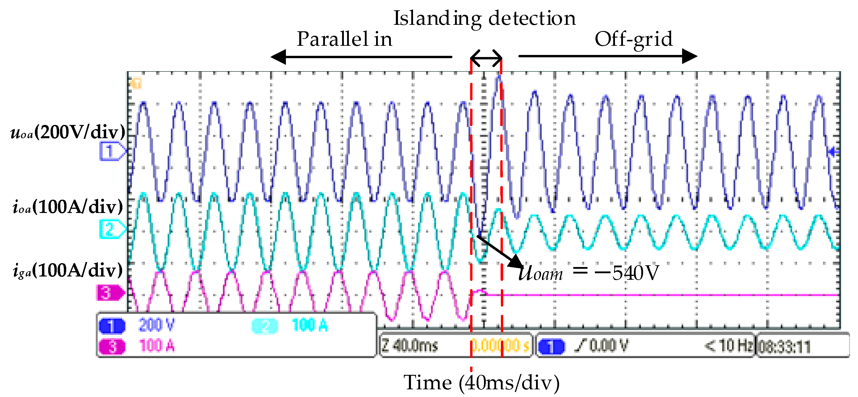
Next, the experimental verification of the multi-functional inverter smooth switching capability under unplanned off-grid conditions is conducted, focusing on whether it can stably output voltage and avoid voltage surges during off-grid detection when an unplanned off-grid event occurs. A grid fault occurs when the controllable protective switch S2 suddenly trips due to a grid fault. Figure 27 shows the experimental waves of the inverter phase A output voltage uₒₐ, the phase A load current ioa, and the phase A grid-connected current iga during an unplanned off-grid event using both traditional PQ/VF mode switching and the multi-modal control strategy.
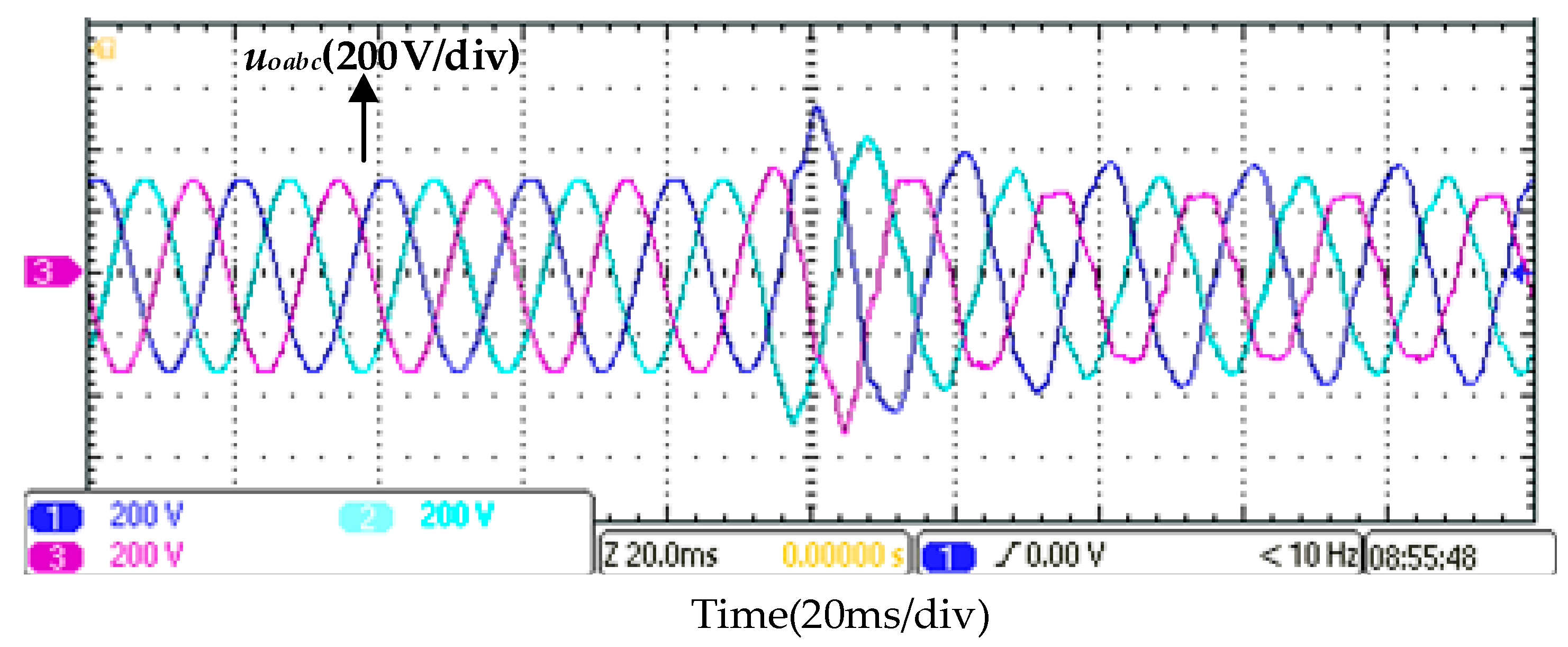
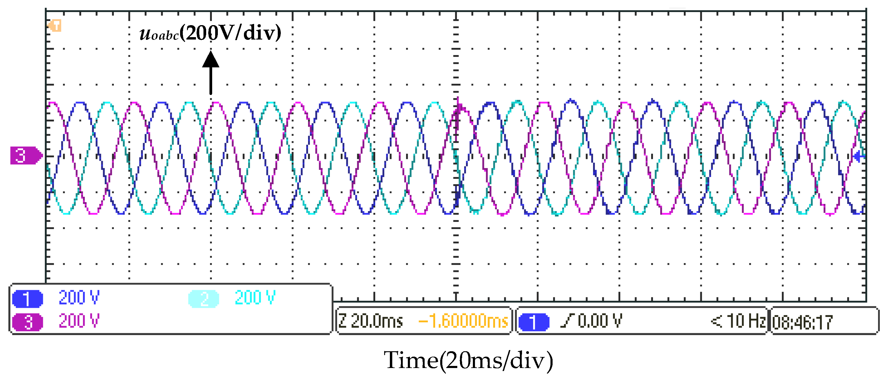
As shown in Figure 27, when a grid fault occurs and the inverter experiences unplanned off-grid mode, the phase A grid-connected current iga drops to zero. During the off-grid detection period, the grid-connected inverter remains in grid-connected control mode (current control mode). Figure 28 reveals that under the traditional switching strategy, the peak value of the phase A inverter output voltage uoa suddenly increases during off-grid detection. The positive peak surges from 311 V to approximately 400 V, while the negative peak reaches around −524 V. This occurs because the inverter output voltage loses grid support and becomes uncontrollable, causing grid-connected power that should be fed to the grid to entirely flow to the load. After off-grid detection ends, inverter switch S1 disconnects, and the grid-connected inverter switches from PQ control to grid-forming control. Following the control mode transition, the inverter output voltage gradually stabilizes to normal values after one cycle. Additionally, influenced by non-linear and unbalanced loads, the inverter output voltage uoabc exhibits severe distortions and three-phase imbalances during off-grid detection and off-grid mode, as shown in Figure 27. The voltage quality of three-phase output voltage uoabc in off-grid mode fails to meet national standards.
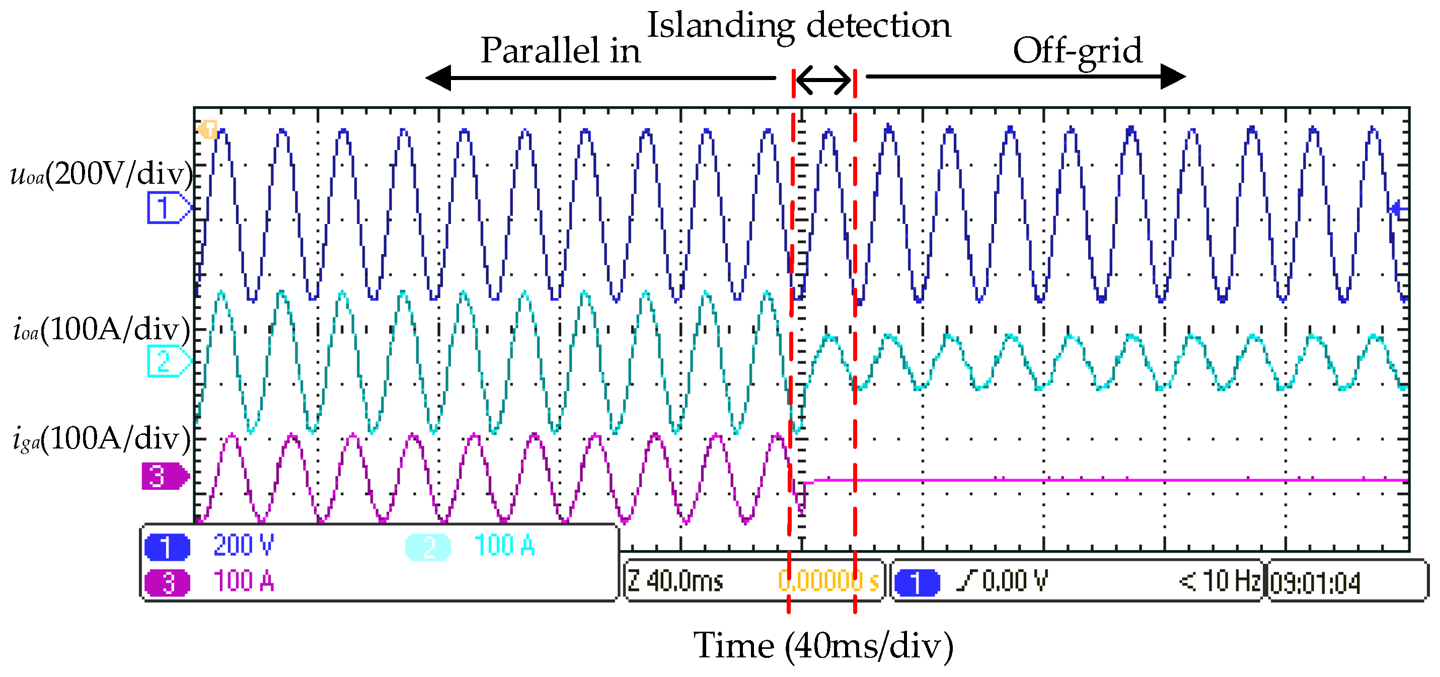
Figure 29 shows the experimental waves of the inverter phase A output voltage uoa, the phase A load current ioa, and the phase A grid-connected current iga during an unplanned off-grid event using the multi-modal control strategy.
As shown in Figure 29, when the multi-modal control strategy is adopted for the main multi-functional inverter during unplanned off-grid events, the peak voltage variation in the inverter output voltage uoabc is extremely small. The phase A voltage uoa increases from approximately 311 V to 324 V. Compared with the phase A voltage surge from 311 V to 400 V in Figure 27, this strategy significantly reduces the output voltage surges during unplanned off-grid transitions. This is because during the off-grid detection period, the improved composite harmonic voltage controller acts as a load voltage stabilizer, while its control quantity is set to the rated load current value. Through the coordinated operation of the improved composite harmonic voltage controller, the outer power controller, and grid-connected current feed-forward igd, the reference value isdref of the inner current controller matches the actual load current, thereby mitigating the inverter output voltage surges and achieving smooth and seamless unplanned off-grid transition.
Additionally, during both the off-grid detection period and off-grid mode, the multi-modal control strategy significantly alleviates the severe distortions and three-phase imbalances in the inverter output current and PCC voltage caused by non-linear and unbalanced loads, as demonstrated in Figure 30.
As shown in Figure 29 and Figure 30, the multi-modal control strategy enables the inverter to achieve smooth unplanned off-grid capability. The inverter output voltage rises slightly without voltage surges during off-grid detection, and the output current changes smoothly. After off-grid detection is completed, the multi-functional grid-connected inverter switches from current control to voltage control.
The experimental waves of the two control strategies in Figure 28 and Figure 30 are in good agreement with the simulation waves in Figure 13 and 15. Both experiments and simulations demonstrate that the proposed multi-modal control strategy for grid-connected inverters could realize smooth unplanned transitions from grid-connected mode to off-grid mode.
The experimental results verify that the proposed smooth control strategy for multi-functional inverters considering dynamic unbalanced loads not only enables the inverter to operate in various modes and achieve active/passive seamless transitions between grid-connected and off-grid states but also provides power quality governance auxiliary services for non-linear and unbalanced loads in microgrids. Specifically, this strategy reduces voltage surges during switching by over 60% and lowers off-grid voltage THD from 7% to below 3%.

7. Summary and Future Work

In microgrids, to reduce voltage surges and harmonic distortions caused by dynamic unbalanced loads during switching from unplanned grid-connected to off-grid modes, this paper proposes a droop control-based multi-modal strategy. Through a load voltage stabilizer and a PI-QPR composite controller, the strategy enables the inverter to operate smoothly in five modes. Considering dynamic unbalanced loads, the proposed smooth mode switching strategy for multi-functional inverters is stable, reliable, and easy to implement in practical projects. It effectively mitigates voltage surges and distortions during unplanned off-grid mode with non-linear loads, simultaneously enables power tracking and harmonic mitigation in grid-connected mode, and also provides stable voltage and frequency power supply in off-grid mode. This control strategy for smoothing unplanned grid-connected/off-grid transitions of multi-functional inverters in microgrids with dynamic unbalanced loads significantly improves transient performance and offers a reliable solution for microgrids.
Future research will focus on the verification of the proposed strategy in a physical microgrid setup, which will include testing its performance in more complex scenarios, such as the critical case of a dynamic unbalanced/non-linear load step applied directly during the switching instant. Further investigations will also explore the extensibility of the method in hybrid microgrids integrated with diverse renewable sources, as well as the incorporation of artificial intelligence for adaptive mode-switching under uncertain load dynamics.

Author Contributions

J.S.: Conceptualization, Methodology, Software, and Writing—Original Draft. H.Z.: Validation, Formal analysis, and Investigation. X.S.: Resources, Data Curation. Y.G.: Writing—Review and Editing, and Visualization. K.Z.: Supervision and Project administration. C.L.: Software and Investigation. X.L.: Supervision, Funding acquisition, and Writing—Review and Editing. All authors have read and agreed to the published version of the manuscript.

Funding

This work was supported by the Science and Technology Project of State grid Sichuan Electric Power Company—Key Technologies for Flexible Networking and Multi-mode Operation of Distributed Resources (Project No. 521997220031).

Data Availability Statement

The original contributions presented in this study are included in the article. Further inquiries can be directed to the corresponding author.

Conflicts of Interest

Authors Jinhao Shen, Hua Zhang, Xueneng Su, Yiwen Gao, Kun Zheng and Cheng Long were oyed by the company State Grid Sichuan Electric Power Research Institute. The remaining authors declare that the research was conducted in the absence of any commercial or financial relationships that could be construed as a potential conflict of interest. The authors declare that this study received funding from Science and Technology Project of State grid Sichuan Electric Power Company. The funder was not involved in the study design, collection, analysis, interpretation of data, the writing of this article or the decision to submit it for publication.

References

  1. Sunjaq, A.; Chen, P.; Bongiorno, M. Frequency control by BESS for smooth Island transition of a hydro-powered microgrids. IET Smart Grid 2024, 7, 63–77. [Google Scholar] [CrossRef]
  2. IEC TS 62898-1:2017+AMD1:2023 CSV; Microgrids—Part 1: Guidelines for microgrid projects planning and specification. International Electrotechnical Commission: Geneva, Switzerland, 2023.
  3. Shanzah, N.; Sadiq, A. Intelligent islanding detection in smart microgrids using variance autocorrelation function-based modal current envelope. IET Smart Grid 2024, 7, 1019–1035. [Google Scholar]
  4. Mehdi, B. Control method for improvement of power quality in single interlinking converter hybrid AC-DC microgrids. IET Smart Grid 2021, 4, 414–428. [Google Scholar]
  5. Nwaulu, E.; Masaud, T.M. Stochastic risk-managed reserve dispatch for seamless microgrids islanding during unplanned events. J. Eng. 2025, 2025, e70035. [Google Scholar] [CrossRef]
  6. Liu, Z.; Liu, J. Indirect current control based seamless transfer of three-phase inverter in distributed generation. IEEE Trans. Power Electron. 2014, 29, 3368–3383. [Google Scholar] [CrossRef]
  7. Deng, Y.; Tao, Y.; Chen, G.; Li, G.; He, X. Enhanced power flow control for grid-connected droop-controlled inverters with improved stability. IEEE Trans. Ind. Electron. 2016, 64, 5919–5929. [Google Scholar] [CrossRef]
  8. Ashabani, S.M.; Mohamed, Y.A.-R.I. A flexible control strategy for grid-connected and islanded microgrids with enhanced stability using nonlinear microgrids stabilizer. IEEE Trans. Smart Grid 2012, 3, 1291–1301. [Google Scholar] [CrossRef]
  9. Ankita, S.; Rajasekharareddy, C.; Kumar, K.V.P. Model Predictive Control of MMC-based Medium Voltage microgrids for grid Connected and Islanded Operation. IEEE Trans. Ind. Appl. 2025, 61, 5751–5766. [Google Scholar] [CrossRef]
  10. Hmad, J.; Houari, A.; Trabelsi, H.; Machmoum, M. Fuzzy logic approach for smooth transition between grid-connected and stand-alone modes of three-phase DG-inverter. Electr. Power Syst. Res. 2019, 175, 105892. [Google Scholar] [CrossRef]
  11. Ghanbarian, M.M.; Nayeripour, M.; Rajaei, A.; Mansouri, M. Design and implementation of a new modified sliding mode controller for grid-connected inverter to controlling the voltage and frequency. ISA Trans. 2016, 61, 179–187. [Google Scholar] [CrossRef] [PubMed]
  12. Liu, W.; Liu, X. Unplanned off-grid switching strategy considering BES rate characteristic and dynamic PQ control. Dianli Xitong Baohu yu Kongzhi/Power Syst. Prot. Control. 2022, 50, 100–107. [Google Scholar]
  13. Wang, J.; Blake, L.; Andrey, B. Design of a Non-PLL grid-forming Inverter for Smooth microgrids Transition Operation. In Proceedings of the 2020 IEEE Power & Energy Society General Meeting, Montreal, QC, Canada, 2–6 August 2020. [Google Scholar]
  14. Wang, G.; Wang, X.; Gao, X. Improved Seamless Switching Control Strategy for AC/DC Hybrid microgrids. IEEE Access 2021, 9, 55790–55801. [Google Scholar] [CrossRef]
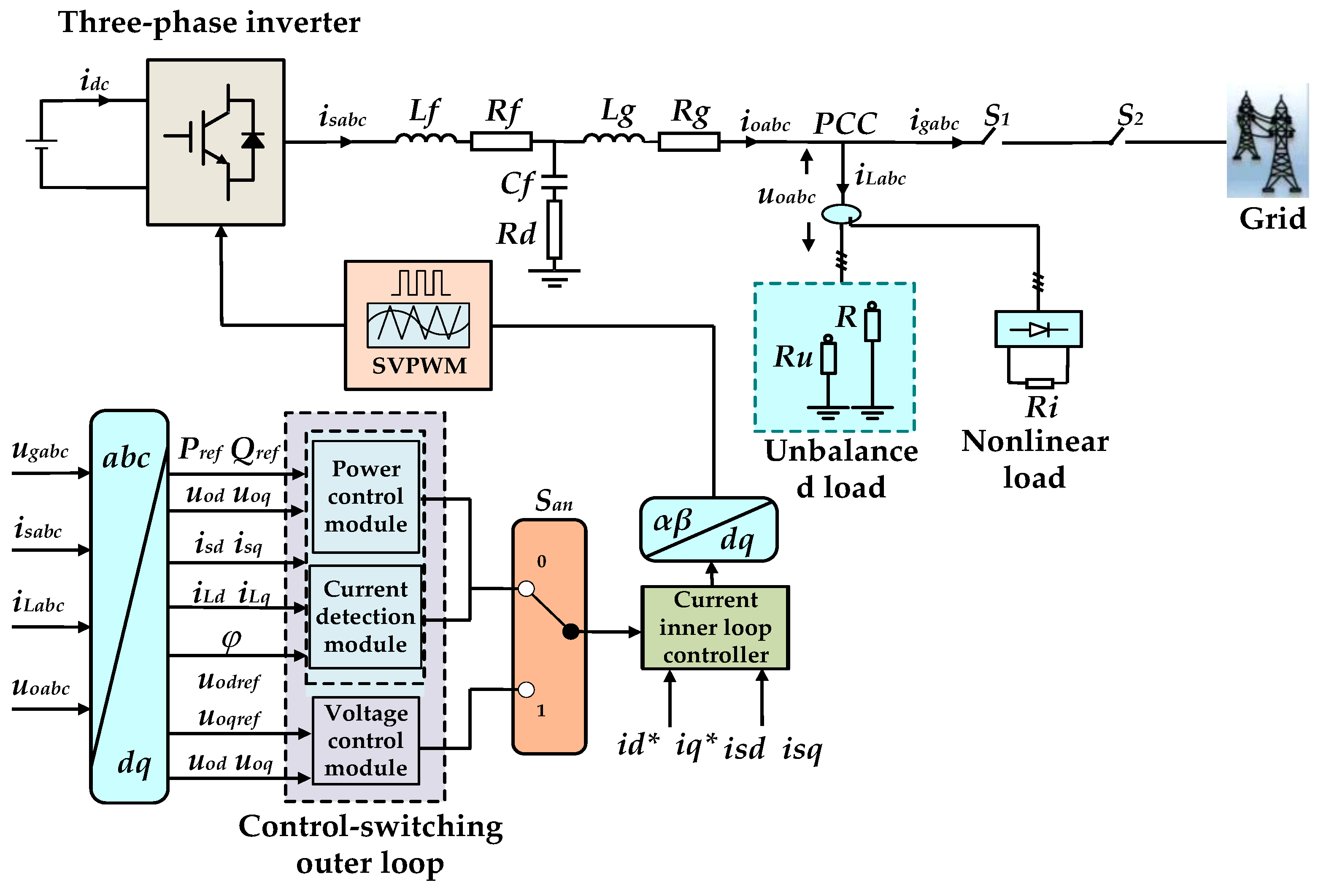
Figure 1. Simplified control structure diagram of microgrids.
Energies 18 06161 g001
Figure 2. Main operating modes of the inverter and switch states.
Energies 18 06161 g002
Figure 3. Improved d-axis control structure for PQ/VF switching.
Energies 18 06161 g003
Figure 4. Load current detection module.
Energies 18 06161 g004
Figure 5. Current detection module after adding delay function.
Energies 18 06161 g005
Figure 6. Improved QPR-LADRC structure.
Energies 18 06161 g006
Figure 7. Multi-functional inverter control diagram in grid-connected mode in dq coordinate system.
Energies 18 06161 g007
Figure 8. Simplified control structure of multi-functional inverter in off-grid mode.
Energies 18 06161 g008
Figure 9. Simplified control structure of multi-functional inverter in grid-connected mode.
Energies 18 06161 g009
Figure 10. Simplified diagram of the multi-functional inverter control structure during off-grid detection.
Energies 18 06161 g010
Figure 11. Multi-modal operations of the multi-functional inverter.
Energies 18 06161 g011
Figure 12. Simulation models of the multi-functional inverter.
Energies 18 06161 g012
Figure 13. Simulated waveforms of output voltage uoabc, grid-connected current igabc, and inverter output current ioabc for full mode of grid-connected inverter with conventional control strategy.
Energies 18 06161 g013
Figure 14. The negative-sequence currents of the conventional switching strategy.
Energies 18 06161 g014
Figure 15. Simulated waveforms of output voltage uoabc, grid-connected current igabc, and inverter output current ioabc of grid-connected inverter in full-mode operation with proposed multi-modal control strategy.
Energies 18 06161 g015
Figure 16. The negative-sequence currents of the proposed multi-modal control strategy.
Energies 18 06161 g016
Figure 17. THD measurements of the inverter output voltage when the conventional strategy and multi-modal control strategy are applied separately in simulation.
Energies 18 06161 g017
Figure 18. Simulations in the dq coordinate system during unplanned off-grid transitions under the proposed multi-modal control strategy.
Energies 18 06161 g018
Figure 19. YuanKuan Energy hardware in the loop experimental platform.
Energies 18 06161 g019
Figure 20. Working principle of YuanKuan experimental platform.
Energies 18 06161 g020
Figure 21. Experimental waves of load current iLabc of inverter in off-grid mode, output voltage uoabc, and output current ioabc of grid-connected inverter.
Energies 18 06161 g021
Figure 22. THD measurements of the inverter output voltage when the conventional strategy and multi-modal control strategy are applied separately in HIL.
Energies 18 06161 g022
Figure 23. Experimental waves of the inverter phase A output voltage uoa, phase A grid voltage uga, and phase A grid-connected current iga at the moment of grid connection under synchronization control.
Energies 18 06161 g023
Figure 24. Experimental waves of power change of inverter in grid-connected mode.
Energies 18 06161 g024
Figure 25. Experimental waveforms of load current iLabc of the multi-functional inverter in grid-connected mode, grid-connected current igabc, and inverter output current ioabc.
Energies 18 06161 g025
Figure 26. THD measurements of the multi-functional inverter in grid-connected mode for grid-connected current igabc.
Energies 18 06161 g026
Figure 27. Experimental waves of phase A output voltage uoa, output current ioa, and phase A grid-connected current iga of the inverter under traditional PQ/VF mode switching before and after unplanned off-grid transition.
Energies 18 06161 g027
Figure 28. Experimental waves of three-phase output voltage uoabc of the inverter applying conventional PQ/VF mode switching before and after unplanned off-grid transition.
Energies 18 06161 g028
Figure 29. Experimental waves of phase A output voltage uoa, output current ioa, and phase A grid-connected current iga of the inverter using the multi-modal control strategy before and after unplanned off-grid transition.
Energies 18 06161 g029
Figure 30. Experimental waves of three-phase output voltage uoabc of the inverter applying the multi-modal control strategy.
Energies 18 06161 g030
Table 1. Simulation parameters of multi-functional inverter.
Parameter NameParameter SymbolsNumerical Values
Inverter-side filter inductanceLs1.5 mH
Filter capacitorC16.5 μF
Grid-side filter inductanceLg0.45 mH
DC-side voltageUdc750 V
Grid phase voltageUg220 V
Grid frequencyf50 Hz
Grid-connected inverter capacityCg60 kW
Switching frequencyfs10 kHz
Asymmetric resistive loads activeP1, P2, P33 kW, 6 kW, 9 kW
Non-linear load DC-side resistanceRi20 Ω
Damping resistanceRc1.5 Ω
Linear load activeP45 kW
Resonance frequency (one)ωn1200 πrad/s
Resonance frequency (two)ωn2600 πrad/s
GainsKr1 Kr22000 rad/s
Observer gain oneβ14000 rad/s
Observer gain twoβ24,000,000 rad/s
P gainkp0.1
I gainki20
Filtering inductor Ls1Ls12 mH
Filtering inductor Ls2Ls21 mH
Filtering capacitor Cf1Cf16.5 μF
BandwidthΩc1 ωc225
Overall controller bandwidthKd35
Disturbance Compensation Coefficientb0476.2
Observer bandwidthωe2000 rad/s
Limiter coefficient of voltageαv1.6
Limiter coefficient of currentILIMIT±50
Disclaimer/Publisher’s Note: The statements, opinions and data contained in all publications are solely those of the individual author(s) and contributor(s) and not of MDPI and/or the editor(s). MDPI and/or the editor(s) disclaim responsibility for any injury to people or property resulting from any ideas, methods, instructions or products referred to in the content.