Review

A Review of Cooling Technology Methods for Electric Vehicle Battery Thermal Management Systems

by
Mohamed Mohamed
1,
Khaled Elleithy
1,* and
Wafa Elmannai
2
1
Department of Computer Science and Engineering, University of Bridgeport, Bridgeport, CT 06604, USA
2
Department of Electrical and Computer Engineering, Manhattan University, Riverdale, NY 10471, USA
*
Author to whom correspondence should be addressed.
Energies 2025, 18(23), 6143; https://doi.org/10.3390/en18236143
Submission received: 20 September 2025 / Revised: 20 October 2025 / Accepted: 19 November 2025 / Published: 24 November 2025
(This article belongs to the Special Issue Challenges and Innovations in Stability and Control of Power Systems)

Abstract

The global issues of air pollution and the energy crisis present significant potential for the development of electric vehicles. However, modern power batteries fall short of conventional internal combustion engine vehicles in several categories, including factors such as cycle longevity, suitability for various environments, range of driving, and charging duration. Battery thermal management (BTM) must be performed well to solve these problems. Enhancing efficiency of electric vehicle batteries is one of the biggest challenges in lowering power usage during electric vehicle battery discharging while driving. Additionally, if the range of electric vehicles is extended, more individuals will acquire them. The cooling system for the battery is one of the main performance issues faced by electric vehicles. This literature review focuses on battery modules that use air and liquid cooling and discusses various cooling configuration arrangements. Liquid, straightforward liquid, and air-cooling strategies are also evaluated, as they can advance battery thermal management systems to a new generation. We aim to address and present various issues related to electric vehicle battery cooling systems, enabling researchers to design and improve current cooling systems for enhanced performance.

1. Introduction

The swift advancement of global economic growth has heightened the demand for mobility and transportation. Conversely, the reliance on fossil fuels as a traditional method of energy conversion for vehicles has begun to be scrutinized considering the increasing global focus on reducing emissions. New energy vehicles play a crucial role in facilitating energy conservation and decreasing CO2 emissions [1]. Power batteries are essential elements for a vehicle classified as a fully electric vehicle [2]. In general, batteries are classified according to the active material used in the battery. Lithium-ion batteries are primarily used to power electric cars due to their advantages over other battery types. These advantages include a lighter weight structure, higher voltage, a long lifespan, and a low self-discharge rate [3,4]. While the batteries are in use, the batteries within a battery pack generate considerable heat, which can significantly impact performance [5]. The importance of an effectively designed battery thermal management system (BTMS) cannot be emphasized enough. It is essential for preserving battery capacity and extending its lifespan. To achieve optimal performance, the temperature of the lithium-ion batteries must be maintained within the range of 25 °C to 40 °C, and the temperature difference between cells should not exceed 5 °C [6]. It is essential to note that once the battery temperature exceeds 50 °C, both the charging speed and efficiency, as well as the overall lifespan, begin to decline. Electrodes produce heat; therefore, for lithium-ion batteries to maintain thermal efficiency, it is essential to modify the electrodes to enhance both ionic and electrical conductivity [7]. Currently, the understanding of how heat is generated in batteries is primarily based on Bernardi’s theory of battery heat generation [8,9]. Electric vehicle batteries undergo chemical reactions when in service. This chemical reaction generates heat, which reduces the battery performance as well as its life span. Therefore, there is a need for some methods to reduce the heat and increase the battery reliability. These methods are air-cooled, liquid-cooled, phase change material (PCM)-based, and thermoelectric-based systems that help to maintain battery health, safety, and lifespan during first charging and heavy use. The primary concern with adding thermal conductivity enhancers is their impact on the overall weight of the battery pack. These enhancer components contribute to the total weight, which must be considered in the complete design of the electric vehicle [10]. To guarantee the secure functioning of batteries, it is essential to implement an inclusive thermal safety management system that can identify potential thermal malfunctions and initiate emergency cooling measures before any incidents occur [11]. A battery thermal management system (BTMS) is crucial for improving efficiency and prolonging the longevity of battery packs in electric vehicles. Considerable research efforts have been made to develop an effective BTMS for electric cars that efficiently removes surplus heat from batteries [12,13]. The battery’s performance will be negatively affected if the operating temperature falls outside the ideal range, whether too high or too low, potentially affecting its longevity, capacity, and heat-related safety features [14,15]. Based on the types of cooling media employed, BTMS technologies can be categorized into three main groups: liquid cooling, air cooling, and phase change material (PCM) cooling. Currently, the most used cooling method is liquid cooling, as shown in Figure 1 [16].
This study examines thermal management models and the latest advancements in cooling methods, with the goal of offering essential support for research into heat generation and the design of cooling systems for power batteries in new energy vehicles.

2. Lithium-Ion Battery Heat Generation

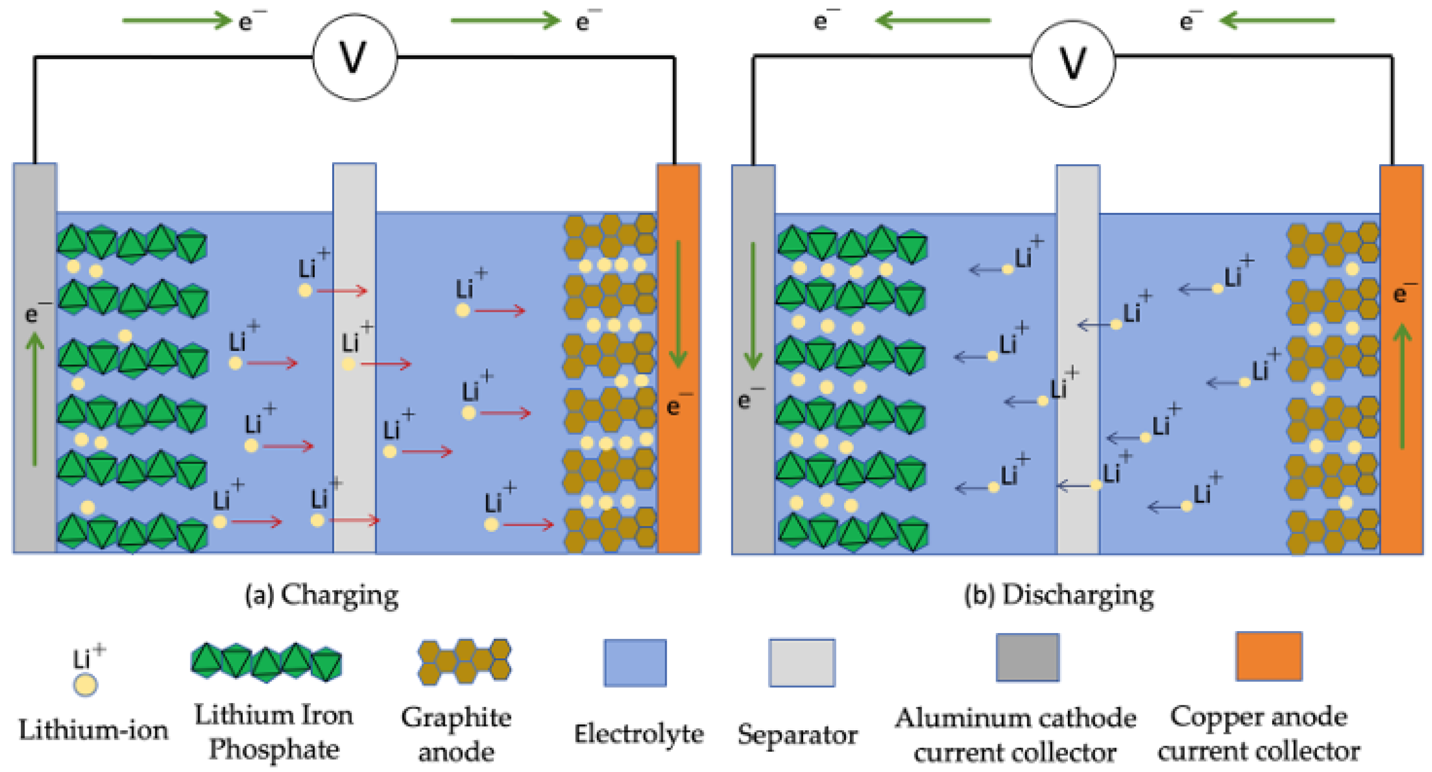
Lithium-ion batteries generate heat primarily due to charge movement and chemical reactions that occur during charging and discharging, as illustrated in Figure 2. In the discharge phase, lithium ions separate from the microporous structure of the graphite anode and become integrated into the lithium-ion phosphate within the battery’s internal configuration; the quantity of lithium ions incorporated indicates the extent of the discharge. Simultaneously, to ensure a balanced transfer of both positive and negative ions, a specific number of electrons also travel through the external circuit between the anode and cathode, thus achieving charge equilibrium and completing the battery’s redox reaction. The heat generated accumulates, significantly affecting the performance, lifespan, and safety of lithium-ion batteries. Therefore, developing an effective heat generation model is crucial for battery thermal management, as it can predict and analyze the behavior of lithium-ion batteries under various operating conditions [16]. As shown in Figure 2.

2.1. Mechanism of Heat Generation

Conventional vehicles use 12 V automobile batteries with different plate sizes (9 p, 11 p, 13 p, etc.). This conventional automobile battery uses positive and negative plates, separator and electrolyte. However, Lithium-ion battery uses positive plates, separator and negative plates. This modern electric vehicle undergoes charging and discharging phases when used heavily. During these stages, the Li-ion battery generates different forms of heat. Many researchers have reported the different forms of heat generation in the Lithium-ion battery. According to D, Bernardi’s examination of heat generation in batteries identifies four primary forms of heat produced: Joule heat Qj, Polarization heat Qp, reaction heat Qr, and side reaction heat Qs [17].
  • Joule heat Qj: The components of batteries, such as electrodes and separators, possess varying levels of electrical resistance, and the heat produced when current passes through these components is referred to as Joule heat. The calculation is expressed in Equation (1).
Qj = I2 R0
In the equation, I represent the current during both charging and discharging, while R0 denotes the internal ohmic resistance of the battery, expressed in ohms (Ω).
2.
Polarization heat, denoted as Qp: During the charging and discharging processes, polarization effects take place, resulting in electrode potentials that differ from their equilibrium values. The heat generated due to these polarization effects is referred to as polarization heat, and it is irreversible. The formula for calculation is shown in Equation (2).
Qp = I2 Rp
In this equation, Rp signifies the battery’s internal polarization resistance, also measured in ohms (Ω).
3.
Reaction heat Qr: When positive or negative electrodes are added or removed, heat is generated due to the movement of lithium ions, referred to as reaction heat. It is commonly understood that reaction heat takes on a positive value during discharging and a negative value during charging. Reaction heat is reversible. The formula for its calculation is given in Equation (3):
Q r = n m Q I M F
In the equation, n represents the number of batteries,  m denotes the mass of each battery in kilograms, Q indicates the total chemical reaction heat in joules, M stands for molar mass in kilograms per mole, and F refers to the Faraday constant in coulombs per mole.
4.
Heat from side reactions Qs: In cases of thermal stress, such as when batteries are overcharged or over-discharged, the electrode materials and electrolytes in lithium batteries produce heat, which adds to the heat from side reactions. If the operating conditions remain normal, this heat can typically be disregarded. Consequently, the total heat produced in the battery pack can be calculated using Equation (4):
Q = I 2   R p + I 2   R 0   +   n m Q I M F
The relevant supporting numerical charging and discharging data from Equations (1)–(4) show overall heat production during charging and discharging at different C-rates at 30 °C are reported by Table 1 in Maher et al. [18].

2.2. Models for Heat Generation

The model for heat generation in lithium-ion batteries is essential. The prevalent heat generation models for batteries include electrochemical-thermal models and electrical-thermal models. Electrochemical-thermal models focus on the electrochemical processes happening within the battery, factoring in how internal chemical reactions contribute to heat generation. On the other hand, electrical-thermal models are based on the heat generated when current flows through the internal resistance of the battery, accounting for energy losses that are subsequently transformed into thermal energy [16].

2.2.1. Electrochemical Thermal Models

This model effectively captures the heat generated and the distribution of potential within lithium batteries during charging and discharging, and it has a wide range of practical uses. It is more than just a theoretical framework; it serves as a basis upon which researchers have developed various electrochemical thermal coupling models utilized across several battery technologies and thermal management systems [16]. Kemper et al. [19] Present a model for a streamlined two-dimensional electrochemical thermal system that enhances our ability to anticipate pulse charges and constant currents. By segmenting the concentration distribution of lithium ions according to the p2d model supposition and determining the potential using the lithium-ion concentration at the boundary, this model reveals promising new avenues for enhancing our understanding of battery performance. In their study in Figure 1 in [20], Nie et al. introduced a technique for simulating batteries of varying sizes (14,650, 18,650, and 26,650) using electrochemical thermal coupling by illustrating a longitudinal view of a commercial lithium-ion cell and a pseudo two-dimensional electrochemical model.
The larger sizes and elevated discharge rates resulted in increased temperatures. A three-dimensional electro-thermal coupling model was created for 30 Ah batteries by Li et al. [21]. Various discharge rates and ambient temperatures were examined to investigate the battery’s internal electrochemical processes and thermal characteristics. They discovered that the discharge rate had a significant impact on the battery’s electrochemical and thermal behaviors, with higher discharge rates causing more heat generation. This finding has significant implications for the design and management of batteries, indicating that regulating the discharge rate can assist in controlling the battery’s temperature [22].

2.2.2. Electrical Thermal Models

The battery equivalent circuit is important to predict and improve its performance. This is essential for optimization of battery design, extending lifespan, state of health and state of charge during electrical and thermal model representation. Therefore, the battery’s equivalent circuit can be formed by incorporating voltage, capacitance, and resistance in both the electrical and thermal models of the battery. Consequently, the thermal model processes the terminal voltage simulation to determine the rate at which heat is generated by the battery [16]. Therefore, the equivalent circuit modifies the resistance and capacitance parameters based on the average temperature, as illustrated by in Figures 1 and 2 of Barcellona et al. [23] define the thermal and electrical models of the battery.
Kim et al. [24] created a model for polymer lithium batteries that include two-dimensional electric thermal interactions. They utilized infrared thermal imaging to confirm the model’s validity by examining the discharge performance and temperature distribution. Xie et al. [25] proposed a dynamic 3-D resistance-based thermal modelwhich enhances the temperature distribution and evolution of the 50 AH battery capacity under various charging and ambient conditions. Li et al. [26] utilized an electro-thermal model to investigate heat generation in batteries during overcharging to improve computing efficiency.

2.3. The Impact of Temperature on Battery Performance

Li-ion batteries possess a complicated structure and undergo chemical reactions during discharge, generating significant heat; therefore, examining battery performance across various temperatures is both crucial and necessary. When charged at high rates without an appropriate cooling system, Li-ion batteries can overheat, which can negatively influence their efficiency, capacity, lifespan, and cycle times, potentially leading to explosions [12,27]. While increased temperatures lower internal resistance, they also cause irreversible changes within the battery, diminishing its capacity, longevity, and output power. As the temperature rises, the rate of aging for the battery accelerates [28]. Over time, when operating at a temperature of 50 °C, the battery’s capacity can decline by 60% after 500 charging cycles [29]. In general, for every 10 °C rise in battery temperature, the rate of internal chemical reactions doubles, reducing its lifespan [30]. At elevated temperatures, the battery experiences capacity reduction due to the formation of dead zones and lithium plating, leading to decreased power output as impedance increases [31,32]. Thus, most lithium batteries function best within an optimal temperature range of 25–40 °C [33,34].

3. Battery Thermal Management System (BTMS)

As previously discussed, the temperature of the battery has a significant impact on the performance of Li-ion batteries. The discharging process generates heat at a high transfer rate, which is a critical factor that raises the temperature considerably. The battery’s low thermal conductivity and thermal contact resistance further exacerbate the temperature gradient within it [1]. The primary challenge faced by the BTMS is to maintain the cell’s temperature within the allowable range while minimizing the thermal gradient throughout the battery.

3.1. Battery Thermal Management System Utilizing Cooling Mechanisms

There are three cooling mechanisms: cabin cooling, direct cooling, and an indirect liquid cooling mechanism.
In cabin cooling, the air within the cabin is utilized to regulate the battery’s temperature; therefore, this method can be implemented when the cabin air has been treated using a typical vapor compression cycle (VCC) system [35]. A schematic representation of this system is shown in the scheme of the cabin cooling mechanism in Figure 2a in Kim et al. [35].
This type of mechanism is straightforward, as it requires only a few extra components to improve airflow around the battery. However, a major disadvantage is that it can compromise passenger comfort inside the cabin due to increased noise, vibrations, and the space required for the system [36].
Direct cooling system: by utilizing the interaction between the coolant and the battery module, the liquid can pass directly through the cell with assistance from the dielectric fluid [37].
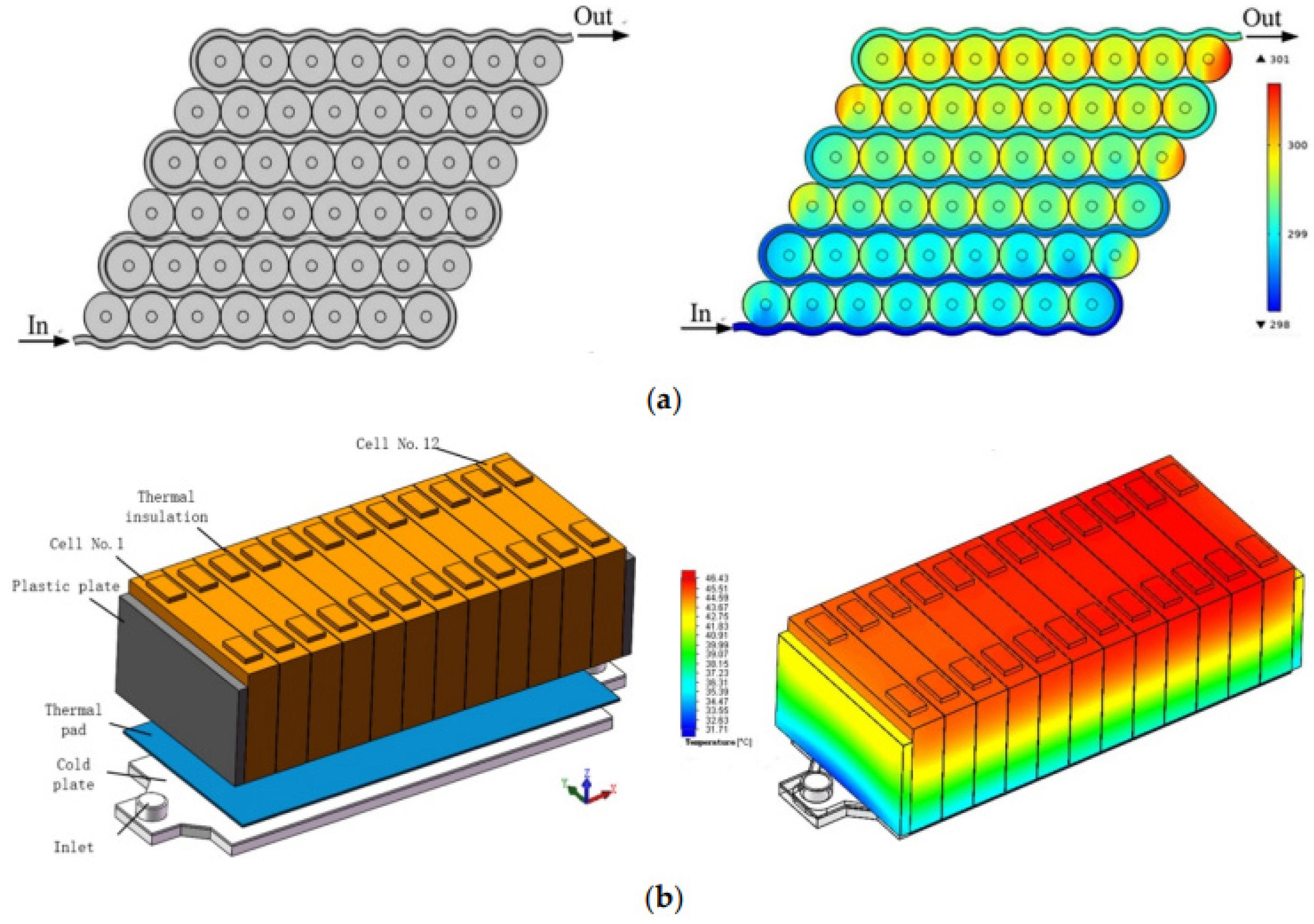
Currently, indirect liquid cooling is a common approach for heat dissipation within the BTMS of new energy vehicles. There are two primary implementation methods illustrated in Figure 3.
(a)
Dispersing heat via the tubes or tube sheets within the battery pack.
(b)
Mounting the batteries onto the liquid cooling plate.
These two methods allow the cooling liquid to circulate through the tubes or the cooling plate, facilitating heat exchange with batteries [16].
The thermal property of the Li-ion is considered at the discharge rate of 2C. These properties are the ambient temperature of 318.15 K; the convective heat transfer coefficient of the battery module is 5 W/(m2·K) and the cooling water at the inlet is 298.15 K in temperature. The battery pack, along with the cooling liquid, flow is a complex geometry. This liquid flow is usually referred to laminar fluid flow. This complex geometry is discretized into normal, finer and extremely fine with the 189,398, 243,570 and 305,716 triangular elements to calculate the exact heat generation and vibration using FEA [38].

3.2. Battery Thermal Management System Utilizing Cooling Mode

3.2.1. Air Cooling Technology

Air cooling technology represents the most traditional form of cooling system in BTMS. This system is defined by its simplicity, direct approach, safety, low viscosity, compact size, lightweight design, affordable maintenance, and minimal initial investment. Numerous studies have shown that the cooling performance of BTMS using air cooling is significantly affected by its structure and airflow. There are two categories of air cooling: passive and active, as illustrated in the schematic diagram in Figure 7a,b in Fu et al. [16].
Kim et al. [39] discovered that passive air cooling consists of air moving from outside the vehicle into the battery pack, effectively cooling the batteries due to the vehicle’s motion. Heat is extracted from the battery pack by air flowing through gaps in the pack and subsequently exiting from the opposite side. Thus, this method is best suited for batteries with lower energy density. However, when vehicles encounter high external temperatures and increased demands for heat dissipation from the battery pack, passive air-cooling technology becomes less effective. Consequently, aerodynamic devices like fans must be integrated to enhance air speed and improve heat transfer efficiency. Fan et al. [40] conducted experiments indicating that enhanced airflow can lead to more effective heat removal in a battery pack, resulting in uniform temperature distribution and reduced maximum temperatures. Park et al. [41] noted that the inclusion of fans increases the overall expense of the air-cooling system. On the other hand, the active air-cooling system significantly enhances heat dissipation performance and reliability, making its advantages outweigh the associated costs. Yu et al. [42] reported improved cooling performance with the use of two-directional airflow. They designed an integrated airflow system featuring two types of air ducts with distinct intake channel fans. This system is illustrated in detail with multi views in Figure 5 in Yu et al. [42].
In this setup, the airflow was produced by a fan located in the upper channel, which directed air through the lithium-ion battery after traveling through the guide plate to manage the flow distribution. A secondary channel utilized airflow from fan 2 to maintain the lower part of the battery, which necessitated significant cooling. The simulation results indicated that this model achieved a peak battery temperature of 33.1 °C, representing a reduction of over 9 °C compared to a single-channel system, while effectively managing heat accumulation in the center of the battery. The authors emphasized the crucial role of temperature elevation in lithium-ion batteries during charging and discharging cycles, noting that the heat generated in these processes could substantially increase the battery temperature. They also addressed different cooling methods for electric vehicle batteries, highlighting various strategies. The article primarily discusses the drawbacks of liquid and phase change material (PCM) cooling systems, even though they are commonly used in electric vehicle battery cooling solutions. The researchers proposed that air cooling is a superior option for lithium-ion battery thermal management systems due to several factors [43], such as its straightforward design, energy consumption, and cost-effectiveness. The battery system investigated consisted of three battery modules with two distinct cooling configurations. Due to the air vents positioned on the holding plates, the airflow within the staggered battery arrangement experienced periodic compression and expansion along the horizontal airflow pathway. It is recommended to implement forced air convection cooling to tackle critical thermal challenges associated with the tested battery pack, which natural convection cooling cannot effectively solve, thereby ensuring optimal battery efficiency and safe operation while prolonging the lifespan of the lithium-ion battery. Furthermore, to provide accurate guidelines for designing an effective battery pack with air cooling, the influences of air supply velocities and discharging rates on the transient thermal behaviors of the staggered battery pack with longitudinal airflow were thoroughly analyzed. The system is illustrated as a schematic illustration of the battery pack arranged in a staggered formation in Figure 1 in [43] and a schematic diagram of the experimental setup in Figure 2 in [43].
The strength of the article lies in its practical approach to demonstrating the effectiveness of lithium-ion battery air cooling. However, a drawback of the article is the lack of clarity in the experimental procedures and outcomes. This research [44] explores the mechanisms of battery heat generation and their impact on powertrain systems in electric and hybrid electric vehicles. Following this, the basic design of the air-cooling Battery Thermal Management System (BTMS) is analyzed, along with a variety of innovative design improvements assessed to evaluate the benefits and challenges of implementing an air-cooling BTMS. By presenting novel concepts for battery packs, inventive cooling channel structures, and specialized thermally conductive materials, the efficiency of air cooling is notably enhanced through extensive experimentation and advanced computational numerical simulations. To advance the air-cooling BTMS within the electric and hybrid electric vehicle sectors, this study suggests future research directions and potential solutions grounded in the review. The advantages of air cooling include its simple design, which removes the necessity for cooling loops, ease of integration, low maintenance costs, no risk of liquid leaking into electronics or the cabin, and decreased weight and energy consumption. A well-constructed air-cooling thermodynamic system (BTMS) has generally been adequate for most parallel hybrid electric vehicle applications over the past several decades to meet the performance requirements across various climates. All elements that influence the battery pack need to be fine-tuned to achieve optimal vehicle performance. This is due to the fact that the air-cooling method has a direct effect on the output, cost, and lifespan of battery packs, which in turn affects vehicle performance, manufacturing expenses, and durability. Current research aimed at enhancing the air-cooling BTMS can be categorized into five areas: improvements in cooling channels, enhancements of inlets and outlets, design upgrades for battery packs, advancements in thermally conductive materials, and enhancements to secondary channels. To achieve the smallest possible battery pack volume and maximum specific energy, the design of the battery pack can be optimized by rearranging the battery cells and subsequently refining the cooling channel. The next aim of the optimization efforts is the design of the cooling channels. To boost cooling efficiency, some research has focused on refining the designs of the inlets and outlets. Different cooling channel designs, such as the Z-type cooling channel, U-type cooling channel, and J-type cooling channel, are illustrated in Figure 3 in Zhao et al. [44], and a battery pack made up of three stacks, where lithium-ion battery cells are arranged in an alternating pattern on each stack as shown in Figure 2 in [44].
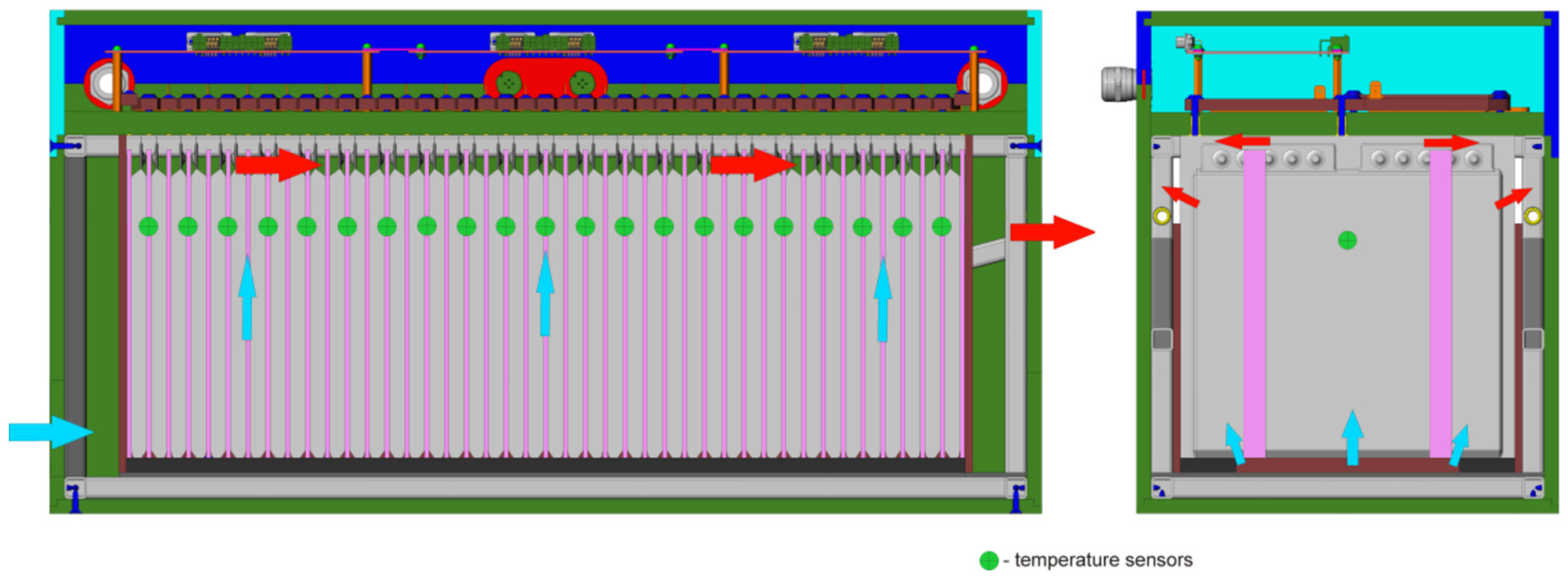
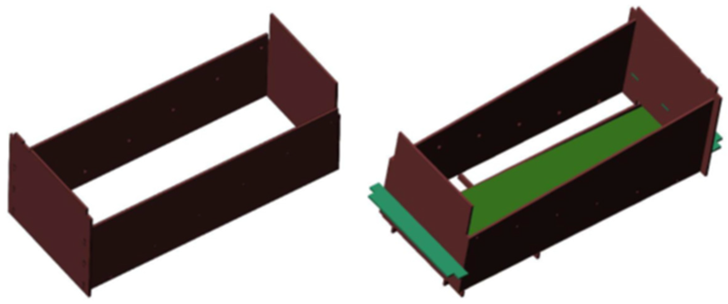
The article [45] initially highlighted that lithium-ion cells are predominant in electric vehicle battery markets and emphasized the significance of cooling for these batteries. In high-capacity batteries containing lithium-ion cells, various temperature conditions exist, with significant disparities. Due to the interactions among surrounding components, the central cells tend to reach higher temperatures than those on the edges without forced cooling. The authors designed a battery consisting of 42 lithium-ion cells. All cells are connected in a series of units with three battery modules. The electrical terminals of the cells link through a single insulating board and specialized clamps. The module body includes two plastic casings: an inner casing that directs airflow and an external protective casing made of metal. A radial fan provides cooling by directing air into the space formed by the plastic shells and then through the areas in between them. As the air ascends along the cells, it absorbs heat generated during charging or discharging processes. The heated air is then expelled into the surrounding environment. The design of the developed battery module and its cooling flowchart are illustrated on the battery management system’s (BMS) boards located at the top. One battery module was built for laboratory testing, and the 3D models created were used to produce new and modified components. Considering its essential role in redistributing the heat-carrying substance, the modules inside the casing underwent the most significant changes. Figure 4 and Figure 5 below illustrate the comparison between the original and revised inside casing designs. The modifications implemented made it possible to lower both maximum and average cell temperatures, improving cooling and reducing the likelihood of module failure.
The article’s strengths include a straightforward explanation of the developer battery module and a clear experiment. However, a drawback of the article is the absence of detailed steps for the experiment, which would illustrate the significant changes in the batteries. Park [46] evaluates the cooling efficiency of various forced air inlets and outlet ducts through simulations of different duct designs, as displayed in Figure 4 in Park [46]. The battery comprises 72 individual units arranged in two rows, with each row featuring a battery channel for airflow numbered 36 through 37. The dimensions of the system are 255 mm (about 10.04 in) by 191 mm (about 7.52 in) by 787 mm. The simulations revealed that models (a), (b), and (c) reached high maximum temperatures (exceeding 90 °C) and pressure levels. In contrast, models (d) and (e) recorded maximum temperatures of 61.9 °C and 58 °C, respectively, with pressure drops that still adhered to the predefined constraints.
This paper [47] proposed modifying minivan vehicles from internal combustion engines (ICE) to electric cars. The components of a modified electric vehicle:
  • Electrical vehicle components made from a minivan weighed about 900 kg (about 1984.16 lb). The vehicle was driven for 70 km at a speed of 70–90 km per hour. The temperature display screen was not over 35 °C, and the ambient temperature was 29 °C.
  • Battery from 94 pcs NMC CATL 3.6 v and 50 AH connected in series.
  • Heat generation model: the heat source from the Li-ion battery is composed of two sources, first from the joule effect and the other from the electrochemical reaction. The temperature increases from heat generation in three cases, which are 34 °C, 60 °C, and 72 °C.
  • Battery thermal management system (BTMS): The airflow cooling system consists of 6 fans that move 150 cubic feet per minute. The installed equipment in a converted EV is shown in Figure 1 in Siriboonpanit et al. [47].
This research demonstrated the assessment of battery arrangement and heat generation based on the principles of thermodynamics and a simulation model using solid work. The installed modeling of surface temperature under a 200 A load is shown in Figure 6 in Siri-boonpanit et al. [47]; the protection system is designed to regulate the temperature below 60 °C to avoid thermal runaway. The air-cooling system for the battery pack, specifically developed for smaller converted EVs, is not only the safest option but also the most economical method for battery installation in electric vehicles. However, for larger electric vehicles with a driving motor that exceeds 30 kW, an extra battery pack may be required to sustain the current in the battery pack and prevent the battery cell from overheating.

3.2.2. Liquid Cooling Technology

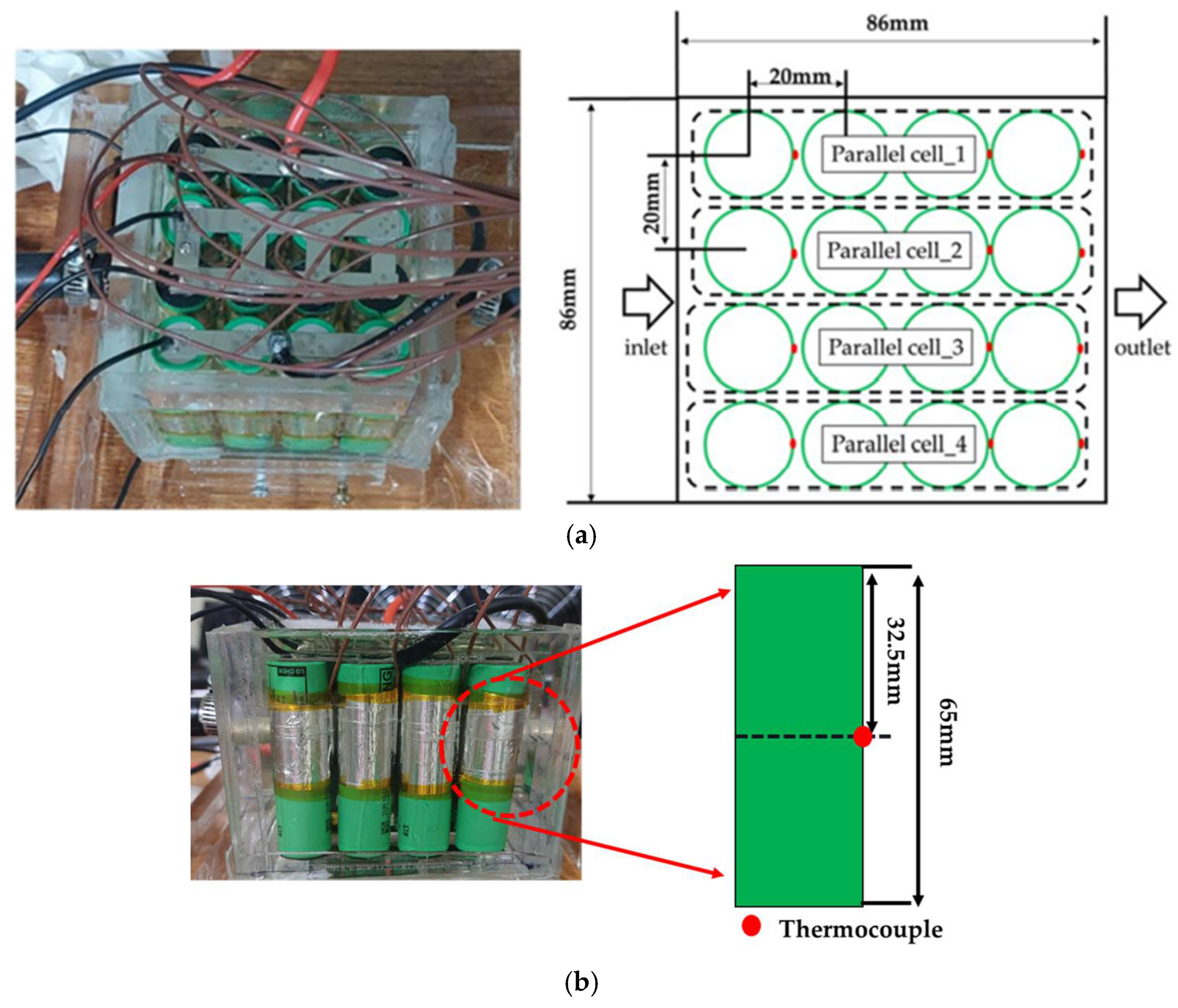
In addition to using air for cooling, liquid cooling is another conventional technique employed in Battery Thermal Management Systems (BTMS). Liquid cooling typically provides greater cooling potential and more effective heat dissipation and is especially beneficial for larger battery packs when compared to air cooling. There are two categories of liquid cooling: direct and indirect. In the direct method, the cooling fluid makes direct contact with the battery, while in the indirect method, the working fluid flows through tubing or a cold plate that connects to the battery. Han et al. [48] conducted experiments to investigate the thermal management of lithium-ion batteries by examining the discharge and heat transfer properties of dielectric immersion cooling systems in their study. As the discharge rate increases from 1C to 4C, the discharge capacity declines from 13.06 Ah to 8.136 Ah. However, at a 3C discharge rate, the capacity shows a slight increase from 10.61 Ah to 10.73 Ah, while at 4C, it shifts from 10.64 Ah to 10.72 Ah as the volume flow rate rises from 400 mLPM to 1000 mLPM. Raising coolant inlet temperatures from 15 °C to 35 °C increases the discharge capacity from 6.73 Ah to 11.88 Ah at 3C and from 5.61 Ah to 10.34 Ah at 4C. Improved cooling resulting from elevated flow rates and lower temperatures diminishes battery operating voltage and capacity. For immersion cooling at a 4C discharge rate, the temperature of the battery pack reduces from 56.18 °C to 52.93 °C, while the heat transfer coefficient rises from 1109.02 W/m2·K to 2884.25 W/m2·K with increasing flow rates. Conversely, at elevated coolant temperatures, the battery pack temperature increases from 38.94 °C to 58.06 °C, and the heat transfer coefficient declines from 2290.19 W/m2·K to 1639.79 W/m2·K, as depicted in Figure 6 [48].
Park and Jung [49] investigated the direct cooling performance of various heat transfer fluids in cylindrical battery configurations, utilizing the schematic displayed in Figure 6. They analyzed the model through finite difference simulations, testing both air and liquid as working fluids. The simulation results revealed that water cooling demands more power, particularly under high cooling loads, as illustrated in Figure 2 in Park et al. [49].
Gomathi et al. [50] presents a practical experiment aimed at enhancing the performance of electric vehicles through improved thermal management solutions. An indirect cooling liquid is utilized to cool a battery module during its operation. The article elaborates on the details and goals of the experiment. A temperature sensor is integrated into the battery. If the temperature of the battery exceeds 44 °C, the cooling system is triggered. The temperature sensor’s output is linked to the Fuzzy system, a schematic representation, using a fuzzy system in a microcontroller as illustrated in Figures 2 and 3 in Gomathi et al. [50].
This research study concentrates on developing a thermal management system for a boxed lithium-ion phosphate battery module utilizing thermoelectric cooling (TEC). It contrasts this system with a traditional cooling approach that incorporates both thermoelectric and liquid cooling methods. A significant element of this research is the optimization of the thermal management system to reduce peak temperatures. The control system is illustrated in Figures 2 and 3 in Gomathi et al. [50]. The advantages of the article: The authors provide a practical discussion on battery cooling for electric vehicles using a liquid cooling system. Disadvantages of the article: The article overlooks alternative cooling methods. Niall P. Williams and colleagues [51] present an experimental study of a battery module featuring four LiFePo4 cylindrical cells connected in parallel electrically and fully immersed in the dielectric fluid Novec 7000. This investigation explores the use of two-phase immersion cooling. The module is composed of:
  • Four LiFePO4 cylindrical cells connected in parallel. Each cell measures 26 mm in diameter and 65 mm in height, with a capacity of 2.5 Ah and a voltage of 3.3 V.
  • The cell module is housed within a steel chamber with internal dimensions of 0.1 m × 0.1 m × 0.2 m and is submerged in the dielectric fluid Novec 7000. The fluid’s saturation temperature is 34 °C at 1 atm. This experiment is constructed from materials that are compatible with the working fluid, minimizing liquid loss and contamination during operation.
  • Gaskets and O-rings are used to seal the chamber.
  • Polycarbonate windows are positioned on two sides of the chamber, allowing access for charging and discharging processes.
  • Power connections to the cells are made through a 6 mm2 tri-rated cable attached to the copper busbar, connecting the cells electrically in parallel. A diagram of battery units inside the testing chamber is shown in Figure 2 in Williams et al. [51].
The analysis showed that the surface temperature of all cells within the module remained below the recommended operating threshold for lithium-ion cells, with a peak temperature increase of 2.2 °C under the highest discharge rate examined.

3.2.3. The Two-Phase Cooling

Using a cooling medium like liquid would be ideal when the phase change into gas occurs during the cooling process. This approach would improve heat transfer efficiency and enhance the cooling capacity of the battery [1]. Al-Zareer et al. [52] designed a battery cooling system based on the ammonia boiling process. It was observed that the maximum temperature could be maintained below 33 °C, with a peak temperature difference of 12 °C and an average temperature of 28 °C. Another iteration of the two-phase cooling system is a heat pipe—Smith et al. [53] created a heat pipe system dedicated to heating the Battery Thermal Management System (BTMS) with a power capacity of 400 W. This system comprised two key components: the “heat pipe cooling plate” which absorbs heat from the battery, and the “remote heat transfer heat pipe”, which conveys heat from the module to the cold plates positioned 300 mm away. The schematic representation of the BTMS heat pipe assembly is shown in Figure 4 in Smith et al. [53].
The experimental findings indicated that the system is capable of absorbing 400 W of heat while ensuring the battery’s maximum temperature stays under 55 °C and the cold plate’s temperature remains below 25 °C at a flow rate of 1 pm. The temperature distribution within the battery was notably consistent, with only about 5 °C variation between the highest and lowest temperatures.

3.2.4. Phase Change Materials (PCMs)

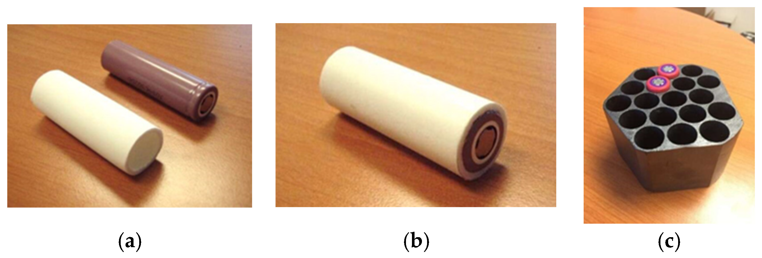
Phase Change Materials refer to substances that absorb or release heat through changing states from liquid to solid or the reverse. PCMs offer a solution for cooling batteries without requiring significant power, unlike many other systems [33]. The PCM system presents benefits such as simplicity, lightness, and high efficiency while not needing additional components like a blower [1]. The article [54] begins by highlighting the benefits of lithium-ion battery packs before concentrating on the factors that affect their performance. It states that thermal conditions are the primary element impacting their performance. The article outlines an effective passive thermal management method and emphasizes battery packs that utilize single lithium-ion cells. The author notes the ideal operating temperature for batteries (between 20 °C and 40 °C) and discusses how battery charging and discharging impact temperature. The article elaborates on both passive and active air-cooling methods for lithium-ion batteries. It stresses that thermal management is crucial for keeping the battery pack’s temperature at the ideal operational level. The author categorizes thermal management strategies into active and passive cooling techniques, weighing their respective pros and cons. The article identifies phase change materials (PCMs) as an efficient form of passive cooling. Phase Change Materials (PCMs) capture heat as they transition from solid to liquid once the designated phase transition temperature is achieved. Producers of thermal management products incorporating PCMs offer a range of composite materials that retain their original solid form while the PCM inside undergoes phase change and absorbs heat, as illustrated in Figure 7.
If the battery cell is kept within a ventilated heat sink capsule, the heat will transfer through the capsule walls. The advantage of the article is the simple description of the passive cooling type. The article’s disadvantage is the limited example of passive cooling types. Himchan et al. [55] examined a thermal management system utilizing paraffin. RT31, RT15, EG26, and EG5 PCM (phase change material) were chosen to keep the battery’s safe operating temperature ranging from 25 °C to 40 °C. The pouch battery comprises four lithium polymer battery modules arranged sequentially within an aluminum container. Each battery is situated on a shared base (aluminum base). Each battery casing features one PCM on both sides. The four batteries utilize four distinct PCMs placed on either side. All batteries are electrically configured in series to manage the charging and discharging processes. The positive terminal of the first battery links to the positive terminal of the load discharge unit, while the negative terminal of the fourth battery connects to the negative terminal of the discharge unit. Sensors are positioned on the surface of the battery, with the PCM located on the outer surface. Following calibration, these temperature sensors are linked to the signal conditioner and a computer monitor to show temperature fluctuations. A schematic representation of the experiment setup layout is illustrated in Figures 1 and 2 in Kim et al. [55].
This research has demonstrated that the maximum temperature occurs at the positive terminal and is distributed towards the negative side of the battery. Consequently, all phase change materials (PCMs) utilizing EG26 and EG5 exhibited enhanced thermal management for lithium polymer pouch batteries. This improvement is expected to significantly boost battery performance, thereby extending battery life. Goli et al. [56] explored the application of graphene-enhanced PCMs. Throughout the experiment, the battery was charged at 16 A and discharged repeatedly at 5 A. The initial experiment employed paraffin before transitioning to graphene. The findings indicated that graphene as a PCM is more effective than both paraffin and the absence of PCM, with temperature reductions reaching up to 5 °C.

3.2.5. Hybrid Cooling System

In addition to utilizing a single cooling material, various studies have investigated the integration of two cooling methods into a hybrid cooling system. Presently, researchers have created a hybrid cooling system that merges PCM with air or liquid cooling [57]. Surya et al. [58] suggested that a superior dual cooling approach includes an external air cooler fan combined with an internal propylene glycol pumping system, working in unison to maintain optimal thermal conditions. The dual cooling system comprises:
  • An external cooling system utilizes a forced air-cooling method.
  • Control of the external cooling system is managed by a motor (air cooling fan) that regulates the battery’s thermal system at an optimal temperature. The motor’s speed increases as the armature input voltage rises, resulting in the air cooler delivering chilled air into the battery. The air cooler motor utilized in this setup is a DC shunt motor, which accelerates as the battery temperature rises. Furthermore, the DC shunt motor circulates the liquid through the cooling channel for internal cooling. A schematic diagram of the external cooling system of the battery is illustrated in Figure 3 in Surya et al. [58]. A PID (Proportional-Integral-Derivative) controller is a control algorithm used in automation to continuously calculate errors based on input values and send corrective output values to help the system reach the desired state. In this application, the PID controller takes the ambient and battery temperatures as inputs and controls the motor pump that cools the battery pack to maintain the battery temperature in the optimal range.
  • Internal cooling uses the liquid Propylene Glycol, a fluid, to cool the battery internally and distribute the temperature evenly. This study shows that double cooling the battery internally and externally leads to the desired performance level. This system can be seen in Figure 2 in [58]. The system improves the battery’s overall performance, durability, and safety standards, emphasizing its effectiveness as an energy storage system.
Saechan et al. [59] conducted a study that involved simulations assessing how the rate of Hydrofluoroether (HFE) Novec—7100 fluid injection affects the heat dissipation effectiveness of 40 cylindrical Li-ion battery packs configured in series and parallel to achieve the target voltage and capacity. The cooling method combined both forced air and liquid spray. The battery packs were arranged in a linear layout with a center-to-center spacing of 2 mm, and the inlet airflow maintained a consistent velocity of 2 m/s. The liquid was delivered through four nozzles placed at the top of the fluid domain. The simulation was executed in two phases, which included the movement of liquid droplets suspended within the air. A significant conclusion drawn from this research includes the following:
  • The utilization of a non-conductive spray played a vital role in minimizing the maximum temperature variance within the densely arranged battery cells.
  • Hydrofluoroether (HFE) droplets with higher flow rates penetrated further into the battery pack, aiding in the reduction in thermal effects on the batteries.
  • The liquid jet should be aimed to make contact with the cell surface to enhance cooling efficiency.
  • While increasing the mass flow rate has a limited effect on temperature regulation and is not economically viable, it is important to optimize the quantity of liquid spray used. Experimental findings indicate that the hybrid spray and cooling system can effectively manage the heat produced by the battery pack, keeping the temperature within the specified limits. The system’s schematic diagram can be found in Figures 1 and 3 in [59].
Reference [60] introduced a hybrid cooling design for a cylindrical Li-ion battery pack utilizing phase change material (PCM) and air. In this design, the PCM core was integrated into a jelly roll, with blue and red lines indicating the air inlet and outlet, respectively, as shown in Figures 1c and 14a,d in [60]. The proposed approach effectively lowered the peak temperature from 66.9 °C to 50 °C, as shown in Figure 14a,d in [60] which illustrates the temperature distribution for both the standard and proposed designs.
Wei et al. [61] suggested integrating air-cooling and two-phase cooling systems. The configuration resembles a typical air-cooling system, featuring an inlet and outlet channel for the primary coolant (airflow), but it also includes extra hydrophilic fibers to facilitate latent heat transfer from water to the battery. A schematic representation of this system is illustrated in Figure 3 in Wei et al. [61].

4. Summary

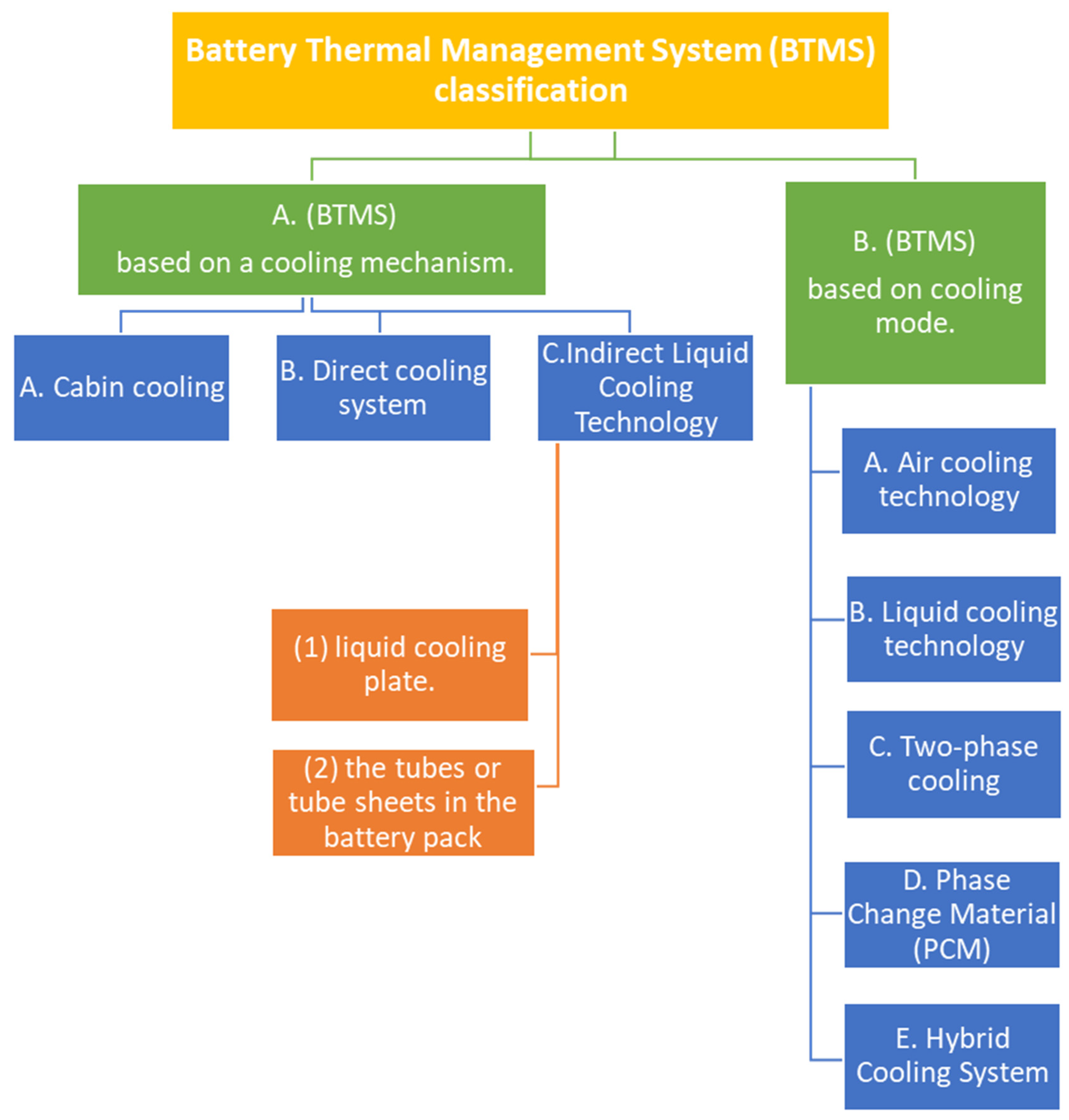
Electric vehicles play a crucial role in conserving global energy and reducing CO2 emissions, with the power battery being a vital part. This paper provides a concise overview of the mechanisms and models of heat generation, highlighting the key principles. The research centers on the advancements in cooling technologies used in the electric vehicle’s battery thermal management system over recent years. The classification of the Battery Thermal Management System (BTMS) and a summary of cooling techniques are illustrated in Figure 8 and Table 1.

5. Conclusions and Discussion

The lithium-ion battery is considered the most advantageous option for electric vehicles; however, it is susceptible to temperature fluctuations, requiring effective thermal management. The primary challenge of the Battery Thermal Management System (BTMS) is to keep operating temperatures within the range of 15 °C to 30 °C; otherwise, the battery capacity may decline, and the risk of fire or explosion may increase. The Battery Thermal Management System (BTMS) for air-cooled batteries boasts a highly efficient manufacturing process and a compact, dependable design, making it perfect for smaller battery configurations. In recent years, the focus of air-cooling systems has primarily been on refining the design of the battery pack, enhancing the cooling channels, utilizing materials with improved thermal conductivity, and exploring the integration of other cooling methods. To address unpredictable battery failures and thermal runaway issues, the current trends in air-cooling system development aim to enhance cooling effectiveness, minimize power usage, and improve high-temperature compatibility. A high heat transfer coefficient characterizes the liquid cooling system. Nevertheless, the indirect liquid cooling Battery Thermal Management System (BTMS) features a complicated design and poses a risk of coolant leaks. Immersion liquid cooling technology utilizes insulation and non-flammable coolants to provide enhanced cooling efficiency by focusing on the selection of appropriate coolants, flow rates, and temperatures. Emerging trends encompass efficient cooling solutions, intelligent regulation, integration of heat management, and lightweight construction. The phase change material (PCM) cooling method features solid–liquid phase change materials and liquid–gas PCMs, exemplified by heat pipes. These systems utilize the properties of phase change materials, which can absorb substantial amounts of heat during phase transitions, resulting in effective cooling performance. Key areas of focus for PCM cooling systems include identifying materials with high thermal conductivity, optimizing system designs, and investigating collaboration with other methods. Looking ahead, PCM cooling system developments are expected to include enhancements in efficiency, miniaturization, integration, and a focus on sustainability. In summary, most researched systems fall short of fully satisfying the need for improving battery thermal management systems (BTMS) in electric vehicles. We intend to further this review by examining each function separately, creating an intelligent structure that enhances performance for electric vehicles while addressing the identified deficiencies. Given the existing technological constraints, a flawless cooling system is not currently available. Looking ahead, the future direction for lithium-ion battery thermal management technology involves integrating various cooling methods to enhance overall performance and efficiency. It is possible to select and combine suitable thermal management technologies, considering the pros and cons of various cooling techniques to address the thermal management requirements of a range of users. Additionally, by incorporating sensors and intelligent control, cooling systems can be modified in real-time to regulate the battery temperature with greater precision.

Author Contributions

The work has been primarily conducted by M.M. under the supervision of K.E. and W.E. M.M. wrote the manuscript. The three authors discussed extensively the techniques presented in this paper. All authors have read and agreed to the published version of the manuscript.

Funding

This research received no external funding.

Data Availability Statement

No new data were created or analyzed in this study.

Conflicts of Interest

The authors declare no conflict of interest.

References

  1. Liu, H.; Wei, Z.; He, W.; Zhao, J. Thermal issues about Li-ion batteries and recent progress in battery thermal management systems: A review. Energy Convers. Manag. 2017, 150, 304330. [Google Scholar] [CrossRef]
  2. Conte, F.V. Battery and battery management for hybrid electric vehicles: A review. Elektrotechnik Inf. 2006, 123, 424–431. [Google Scholar] [CrossRef]
  3. Silvestri, L.; De Santis, M.; Falcucci, G.; Serao, P.; Bella, G. Evaluation of Battery Power Losses During the LCA Use Phase of Electric Vehicles: An Experimental Analysis of Different Li-Ion Battery Chemistries; SAE Technical Paper; SAE: Warrendale, PA, USA, 2023. [Google Scholar]
  4. Pesaran, A.A. Battery thermal models for hybrid vehicle simulations. J. Power Sources 2002, 110, 377–382. [Google Scholar] [CrossRef]
  5. Sato, N. Thermal behavior analysis of lithium-ion batteries for electric and hybrid vehicles. J. Power Sources 2001, 99, 70–77. [Google Scholar] [CrossRef]
  6. Wang, H.; Tao, T.; Xu, J.; Shi, H.; Mei, X.; Gou, P. Thermal performance of a liquid-immersed battery thermal management system for lithium-ion pouch batteries. J. Energy Storage 2022, 46, 103835. [Google Scholar] [CrossRef]
  7. Zhao, R.; Zhang, S.; Liu, J.; Gu, J. A review of thermal performance improving methods of lithium-ion battery: Electrode modification and thermal management system. J. Power Sources 2015, 299, 557–577. [Google Scholar] [CrossRef]
  8. Doyle, M.; Fuller, T.F.; Newman, J. Modeling of Galvanostatic Charge and Discharge of the Lithium/Polymer/Insertion Cell. J. Electrochem. Soc. 1993, 140, 1526–1533. [Google Scholar] [CrossRef]
  9. Bernardi, D.; Pawlikowski, E.; Newman, J. A General Energy Balance for Battery Systems. J. Electrochem. Soc. 1985, 132, 5–12. [Google Scholar] [CrossRef]
  10. Hwang, F.S.; Reidy, C.; Picovici, D.; Callaghan, D.; Culliton, D.; Nolan, C. Review of battery thermal management systems in electric vehicles. Renew. Sustain. Energy Rev. 2024, 192, 11417. [Google Scholar] [CrossRef]
  11. Li, W.; Zhou, Y.; Zhang, H.; Tang, X. A Review of Battery Thermal Management for New Energy Vehicles. Energies 2023, 16, 4845. [Google Scholar] [CrossRef]
  12. Rao, Z.; Wang, S. A review of power battery thermal energy management. Renew. Sustain. Energy Rev. 2011, 15, 4554–4571. [Google Scholar] [CrossRef]
  13. Wang, Q.; Jiang, B.; Li, B.; Yan, Y. A critical review of thermal management models and solutions of lithium-ion batteries for the development of pure electric vehicles. Renew. Sustain. Energy Rev. 2016, 64, 106–128. [Google Scholar] [CrossRef]
  14. An, Z.; Jia, L.; Ding, Y.; Dang, C.; Li, X. A review on lithium-ion power battery thermal management technologies and thermal safety. J. Therm. Sci. 2017, 26, 391–412. [Google Scholar] [CrossRef]
  15. Xia, G.; Cao, L.; Bi, G. A review on battery thermal management in electric vehicle application. J. Power Sources 2017, 367, 90–105. [Google Scholar] [CrossRef]
  16. Fu, P.; Zhao, L.; Wang, X.; Sun, J.; Xin, Z. A Review of Cooling Technologies in Lithium-Ion Power Battery Thermal Management Systems for New Energy Vehicles. Processes 2023, 11, 3450. [Google Scholar] [CrossRef]
  17. Liu, X. Research on Heat Production Model and Thermal Management of High-Rate Soft-Pack Lithium-Ion Battery. Master’s Thesis, Harbin Institute of Technology, Harbin, China, 2021. [Google Scholar]
  18. Maher, K.; Boumaiza, A.; Amin, R. Understanding the heat generation mechanisms and the interplay between joule heat and entropy effects as a function of state of charge in lithium-ion batteries. J. Power Sources 2024, 623, 235504. [Google Scholar] [CrossRef]
  19. Kemper, P.; Li, S.E.; Kum, D. Simplification of pseudo two-dimensional battery model using dynamic profile of lithium concentration. J. Power Sources 2015, 286, 510–525. [Google Scholar] [CrossRef]
  20. Nie, P.; Zhang, S.W.; Ran, A.; Yang, C.; Chen, S.; Li, Z.; Zhang, X.; Deng, W.; Liu, T.; Kang, F.; et al. Full-cycle electrochemical-thermal coupling analysis for commercial lithium-ion batteries. Appl. Therm. Eng. 2021, 184, 116258. [Google Scholar] [CrossRef]
  21. Li, H.; Saini, A.; Liu, C.; Yang, J.; Wang, Y.; Yang, T.; Pan, C.; Chen, L.; Jiang, H. Electrochemical and thermal characteristics of prismatic lithium-ion battery based on a three-dimensional electrochemical-thermal coupled model. J. Energy Storage 2021, 42, 102976. [Google Scholar] [CrossRef]
  22. Joula, M.; Dilibal, S.; Mafratoglu, G.; Alipour, M.; Alipour, M. Hybrid Battery Thermal Management System with NiTi SMA and Phase Change Material (PCM) for Li-ion Batteries. Energies 2022, 15, 4403. [Google Scholar] [CrossRef]
  23. Barcellona, S.; Piegari, L. Integrated electro-thermal model for pouch lithium-ion batteries. Math. Comput. Simul. 2020, 183, 5–19. [Google Scholar] [CrossRef]
  24. Kim, U.S.; Shin, C.B.; Kim, C.S. Modeling for the scale-up of a lithium-ion polymer battery. J. Power Sources 2009, 189, 841–846. [Google Scholar] [CrossRef]
  25. Xie, Y.; Zheng, J.; Hu, X.; Lin, X.; Liu, K.; Sun, J.; Zhang, Y.; Dan, D.; Xi, D.; Feng, F. An improved resistance-based thermal model for prismatic lithium-ion battery charging. Appl. Therm. Eng. 2020, 180, 115794. [Google Scholar] [CrossRef]
  26. Li, J.; Sun, D.; Jin, X.; Shi, W.; Sun, C. Lithium-ion battery overcharging thermal characteristics analysis and an impedance-based electro-thermal coupled model simulation. Appl. Energy 2019, 254, 113574. [Google Scholar] [CrossRef]
  27. Klein, M.; Tong, S.; Park, J. In-plane nonuniform temperature effects on the performance of a large-format lithium-ion pouch cell. Appl. Energy 2016, 165, 639–647. [Google Scholar] [CrossRef]
  28. Xie, J. Optimization Investigation on the Cooling Structure of Lithium-Ion Battery Packages in Electric Vehicles. Master’s Thesis, South China University of Technology, Guangzhou, China, 2018. [Google Scholar]
  29. Ramadass, P.; Haran, B.; White, R.; Popov, B. Capacity fade of Sony 18650 cells cycled at elevated temperatures Part II. Capacity fade analysis. J. Power Sources 2002, 112, 614–620. [Google Scholar] [CrossRef]
  30. Bandhauer, T.M.; Garimella, S.; Fuller, T.F. A Critical Review of Thermal Issues in Lithium-Ion Batteries. J. Electrochem. Soc. 2011, 158, R1. [Google Scholar] [CrossRef]
  31. Yang, Z.; Patil, D.; Fahimi, B. Online estimation of capacity fade and power fade of lithium-ion batteries based on in-put-output response technique. IEEE Trans. Transp. Electrif. 2017, 4, 147–156. [Google Scholar] [CrossRef]
  32. Jaguemont, J.; Boulon, L.; Venet, P.; Dubé, Y.; Sari, A. Lithium-ion battery aging experiments at subzero temperatures and model de-elopement for capacity fade estimation. IEEE Trans. Veh. Technol. 2016, 65, 4328–4343. [Google Scholar] [CrossRef]
  33. Huang, Q.; Li, X.; Zhang, G.; Zhang, J.; He, F.; Li, Y. Experimental investigation of the thermal performance of heat pipe assisted phase change material for battery thermal management system. Appl. Therm. Eng. 2018, 141, 1092–1100. [Google Scholar] [CrossRef]
  34. Zhao, C.; Sousa, A.C.; Jiang, F. Minimization of thermal non-uniformity in lithium-ion battery pack cooled by channeled liquid flow. Int. J. Heat Mass Transf. 2019, 129, 660–670. [Google Scholar] [CrossRef]
  35. Kim, J.; Oh, J.; Lee, H. Review on battery thermal management system for electric vehicles. Appl. Therm. Eng. 2019, 149, 192–212. [Google Scholar] [CrossRef]
  36. Scrosati, B.; Garche, J.; Tillmetz, W. Advances in Battery Technologies for Electric Vehicles; Woodhead Publishing: Sawston, UK, 2015. [Google Scholar]
  37. Wu, W.; Wang, S.; Wu, W.; Hong, S.; Lai, Y. A critical review of battery thermal performance and liquid based battery thermal management. Energy Convers. Manag. 2019, 182, 262–281. [Google Scholar] [CrossRef]
  38. Xie, L.; Huang, Y.; Lai, H. Coupled prediction model of liquid-cooling based thermal management system for cylindrical lithium-ion module. Appl. Therm. Eng. 2020, 178, 115599. [Google Scholar] [CrossRef]
  39. Kim, G.-H.; Pesaran, A. Battery Thermal Management System Design Modeling, National Renewable Energy Laboratory; NREL: Golden, CO, USA, 2006.
  40. Fan, Y.; Bao, Y.; Ling, C.; Chu, Y.; Tan, X.; Yang, S. Experimental study on the thermal management performance of air cooling for high energy density cylindrical lithium-ion batteries. Appl. Therm. Eng. 2019, 155, 96–109. [Google Scholar] [CrossRef]
  41. Park, C.-W.; Jaura, A.K. Thermal Analysis of Cooling System in Hybrid Electric Vehicles; SAE Technical Paper Series; SAE: Warrendale, PA, USA, 2002. [Google Scholar]
  42. Yu, K.; Yang, X.; Cheng, Y.; Li, C. Thermal analysis and two directional air flow thermal management for lithium-ion battery pack. J. Power Sources 2014, 270, 193–200. [Google Scholar] [CrossRef]
  43. Yu, X.; Lu, Z.; Zhang, L.; Wei, L.; Cui, X.; Jin, L. Experimental study on transient thermal characteristics of stagger-arranged lithium-ion battery pack with air cooling strategy. Int. J. Heat Mass Transf. 2019, 143, 118576. [Google Scholar] [CrossRef]
  44. Zhao, G.; Wang, X.; Negnevitsky, M.; Zhang, H. A review of air-cooling battery thermal management systems for electric and hybrid electric vehicles. J. Power Sources 2021, 501, 230001. [Google Scholar] [CrossRef]
  45. Ivanov, I.D.; Velikoretskiy, A.; Sergeevich, A.; Nekrasov, A.; Papkin, I. Lithium-Ion Batteries with Forced Air Cooling: Simulation and Laboratory Tests. Int. J. Eng. Adv. Technol. IJEAT 2019, 9, 5552–5558. [Google Scholar] [CrossRef]
  46. Park, H. A design of air flow configuration for cooling lithium-ion battery in hybrid electric vehicles. J. Power Sources 2013, 239, 30–36. [Google Scholar] [CrossRef]
  47. Siriboonpanit, E.; Sasiwimonrit, K.; Saelao, J.; Patcharaprakiti, N. An Air Force Cooling of Lithium–ion Battery Thermal Management System for Heat Eliminating in Modified Electric Vehicle. In Proceedings of the International Electrical Engineering Congress (iEECON2022), Khon Kaen, Thailand, 9–11 March 2022. [Google Scholar]
  48. Han, J.-W.; Garud, K.S.; Hwang, S.-G.; Lee, M.-Y. Experimental Study on Dielectric Fluid Immersion Cooling for Thermal Management of Lithium-Ion Battery. Symmetry 2022, 14, 2126. [Google Scholar] [CrossRef]
  49. Park, S.; Jung, D. Battery cell arrangement and heat transfer fluid effects on the parasitic power consumption and the cell temperature distribution in a hybrid electric vehicle. J. Power Sources 2013, 227, 191–198. [Google Scholar] [CrossRef]
  50. Gomathi, S.; Janani, G.; Jothishwaren, R.; Nalien, A. Thermo Electric Cooling System for E-Vehicle. In Proceedings of the 5th International Conference on Mobile Computing and Sustainable Informatics (ICMCSI), Lalitpur, Nepal, 18–19 January 2024. [Google Scholar] [CrossRef]
  51. Williams, N.; Trimble, D.; O’Shaughnessy, S. Thermal Management of Lithium-ion Batteries for Electric Vehicles through Immersion Cooling. In Proceedings of the 2023 22nd IEEE Intersociety Conference on Thermal and Thermomechanical Phenomena in Electronic Systems (ITherm), Orlando, FL, USA, 30 May–2 June 2023. [Google Scholar] [CrossRef]
  52. Al-Zareer, M.; Dincer, I.; Rosen, M.A. Development and evaluation of a new ammonia boiling based battery thermal management system. Electrochem. Acta 2018, 280, 340–352. [Google Scholar] [CrossRef]
  53. Smith, J.; Singh, R.; Hinterberger, M.; Mochizuki, M. Battery thermal management system for electric vehicle using heat pipes. Int. J. Therm. Sci. 2018, 134, 517–529. [Google Scholar] [CrossRef]
  54. Steve Wener, S. Passive Thermal Management Optimizes Lithium-Ion Battery Pack Performance. Available online: https://www.edn.com/passive-thermal-management-optimizes-lithium-ion-battery-pack-performance/ (accessed on 8 May 2019).
  55. Kim, H.; Kim, E.; Seo, M.; Kim, T.; Angani, A.; Shin, K. Design of Battery Thermal Management Unit with PCM for Electrical Vehicle: Part II: Experimental Investigation on Pouch Type Battery Cell. In Proceedings of the IEEE Eurasia Conference on IOT, Communication and Engineering, Yunlin, Taiwan, 3–6 October 2019; pp. 255–258. [Google Scholar]
  56. Goli, P.; Legedza, S.; Dhar, A.; Salgado, R.; Renteria, J.; Balandin, A.A. Graphene-enhanced hybrid phase change materials for thermal management of Li-ion batteries. J. Power Sources 2014, 248, 37–43. [Google Scholar] [CrossRef]
  57. Rangappa, R.; Rajoo, S. Effect of thermo-physical properties of cooling mass on hybrid cooling for lithium-ion battery pack using design of experiments. Int. J. Energy Environ. Eng. 2019, 10, 67–83. [Google Scholar] [CrossRef]
  58. Surya, M.; Aravindhan, A.; Yokeshwar, N.; Geetha, N.; Kavitha, D. Thermal Management of Li-ion Battery by Dual Cooling Systems. In Proceedings of the 2024 Second International Conference on Emerging Trends in Information Technology and Engineering (ICETITE), Vellore, India, 22–23 February 2024. [Google Scholar] [CrossRef]
  59. Saechan, P.; Dhuchakallaya, I. Investigation of the Cooling Characteristics of Hybrid Liquid Spray and Air Cooling for an EV Battery Pack. In Proceedings of the 6th International Conference on Electrical Engineering and Green Energy (CEEGE), Grimstad, Norway, 6–9 June 2023. [Google Scholar] [CrossRef]
  60. Zhao, R.; Gu, J.; Liu, J. Optimization of a phase change material based internal cooling system for cylindrical Li-ion battery pack and a hybrid cooling design. Energy 2017, 135, 811–822. [Google Scholar] [CrossRef]
  61. Wei, Y.; Angelin-Chaab, M. Experimental investigation of a novel hybrid cooling method for lithium-ion batteries. Appl. Therm. Eng. 2018, 136, 375–387. [Google Scholar] [CrossRef]
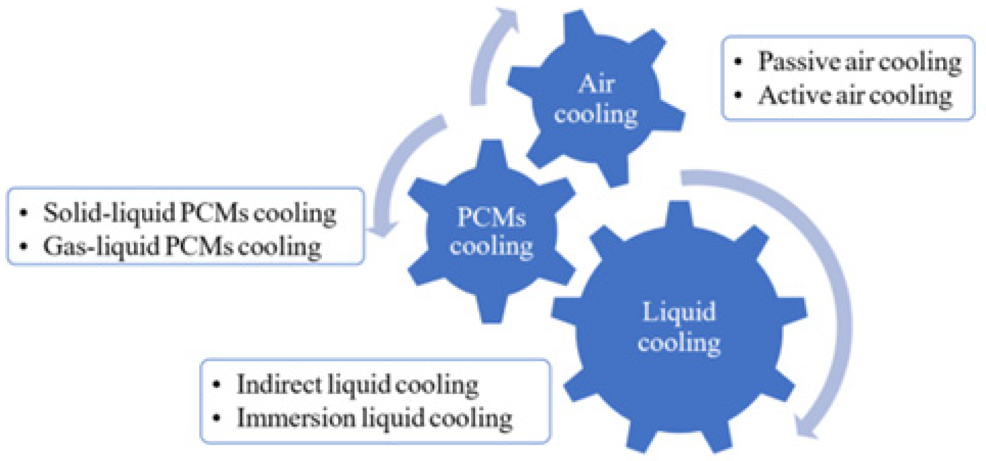
Figure 1. Types of cooling technology in the battery temperature management system [16].
Energies 18 06143 g001
Figure 2. Illustrative scheme of (a) lithium-ion batteries charging process, (b) lithium-ion batteries discharging process [16].
Energies 18 06143 g002
Figure 3. Schematic illustration and thermal contours of (a) tube sheets for indirect cooling, (b) cooling plates [16].
Energies 18 06143 g003
Figure 4. Design of battery module and cooling flow diagram. The blue arrows indicate the upward flow of cold air, while the red arrows indicate the flow of hot air. [45].
Energies 18 06143 g004
Figure 5. A comparison between the original and updated designs of the internal casing, the green section highlights the new design updates. [45].
Energies 18 06143 g005
Figure 6. (a) Setup of a battery pack featuring coolant for direct liquid cooling and (b) One thermocouple is attached to the middle of each battery cell surface to measure the cell temperature [48].
Energies 18 06143 g006
Figure 7. 18,650 Li-ion cells (a) next to PCM sleeve, (b) inserted into PCM sleeve, and (c) PCM block machined to accept 18,650 cells [54].
Energies 18 06143 g007
Figure 8. Battery Thermal Management System (BTMS) classification.
Energies 18 06143 g008
Table 1. Research summary on cooling techniques.
Author NameResearch MethodCooling MethodStrengthWeakness
1. Kim et al. [39]SimulationPassive air coolingLow costLimited effectiveness
2. Fan et al. [40]ExperimentAir cooling The author shows the active air-cooling effects on the batteries during the operation.High cost
3. Yu et al. [43]Experiment SimulationAir cooling. Forced air.Effective practical work, simple design.Unclear experimental steps and results
4. Zhao et al. [44]Experiment and SimulationAir coolingThe advantages of air cooling consist of its straightforward design, which eliminates the need for cooling loops, ease of packing, minimal maintenance costs, zero chance of liquid seeping into electronics or the cabin, and reduced weight and energy usage.Air cooling is inefficient for cooling electric vehicle batteries in high ambient temperatures
5. Ivanov et al. [45]Experiment and SimulationAir coolingThe simple description of the developer battery module and the simple experimentThe experiment’s steps are missing, which would show the major changes in the batteries.
6. Park [46]SimulationAir cooling. Forced air method.The research focused on the benefits of the air-cooling methodAffected by high ambient temperatures.
7. Siriboonpanit et al. [47]Experiment SimulationAir cooling. Forced air method.The research focused on compact electric vehicles, and it is not only the safest but also the most cost-effective way to install batteries in EVs.An additional battery pack might be necessary to maintain the battery’s current and prevent the battery from overheating.
8. Han et al. [48]ExperimentLiquid cooling. Dielectric immersion cooling systems.Enhancing the volume flow rate while lowering the coolant inlet temperature improves the cooling effect to increase the battery performanceProbability of liquid leaks and low performance.
9. Park and Jung [49]SimulationLiquid cooling, direct cooling performance.Low costWater cooling demands more power, particularly under high cooling loads
10. Gomathi et al. [50]ExperimentIndirect cooling liquidThe research is optimizing the thermal management system to minimize the maximum temperature.Low cooling efficiency.
11. Williams et al. [51]ExperimentLiquid cooling. Dielectric fluid Novec 7000.The research proved the effectiveness of applying the two-phase immersion cooling on the BTSMHigh cost, and significant weight.
12. Al-Zareer [52]ExperimentTwo-phase cooling. Ammonia boiling process.The paper practically investigates the use of ammonia as a cooling liquid for the batteriesSignificant safety risks and operational complexities.
13. Smith et al. [53]ExperimentTwo-phase cooling. Heat pipeThe paper provides a practical investigation into the use of a heat pipe in the cooling system for electric vehicle batteries.unsymmetrical temperature over the battery pack.
14. Himchan et al. [55]ExperimentPhase change material. Paraffin. RT31, RT15, EG26, and EG5 PCM.The paper presents a practical investigation into the use of phase change materials (PCMs) in the cooling system for electric vehicle batteries, demonstrating the positive results achieved with a specific material and thickness.Low heat transfer and the likelihood of paraffin leakage.
15. Goli et al. [56]ExperimentPhase change materialPractical investigation into the use of phase change materials (PCMs) in the cooling system for electric vehicle batteries, showing the positive results of using a specific material, resulting in a reduction in the battery temperature by more than 4 °C.Low heat transfer.
16. Surya et al. [58]ExperimentHybrid cooling. External air cooler fan and internal propylene glycol pumping system.This study demonstrates that double cooling of the battery, both internally and externally, enhances performance, durability, and safety, highlighting its effectiveness as an energy storage system.The system adds more weight to the vehicle.
17. Saechan et al. [59]SimulationHybrid cooling. Forced air and liquid spray.The investigation into the use of a hybrid spray and cooling system can be effective in the cooling system for electric vehicle batteries.Not applicable to practical applications due to the limited water volume in the tank.
18. Zhao et al. [60]ExperimentPCM-air cooling. Hybrid design.The proposed design successfully reduced the battery peak temperature by using this hybrid combination.The system increases the vehicle’s weight and has a low heat transfer capability.
19. Wei and Angelin-Chaab [61]ExperimentHybrid cooling with a two-phase air-cooling systemExperimentally, using hybrid cooling with two-phase air-cooling systems improves the cooling system.A complex system incurs additional costs.
Disclaimer/Publisher’s Note: The statements, opinions and data contained in all publications are solely those of the individual author(s) and contributor(s) and not of MDPI and/or the editor(s). MDPI and/or the editor(s) disclaim responsibility for any injury to people or property resulting from any ideas, methods, instructions or products referred to in the content.