1. Introduction
The rapid growth of distributed generation is driving the development of DC microgrids [
1]. As a key link between the DC microgrid and the AC grid, the bidirectional grid-connected converter (BGC) plays a crucial role in maintaining the DC bus voltage stability. For DC microgrids, which are rich in new energy sources and transmit energy to the grid, the BGC can emulate synchronous generators (SGs) using the virtual synchronous generator (VSG) strategy to provide inertia support to the grid [
2,
3].
Most of the work on VSG assumes that the DC side is an ideal voltage source, and for a given AC frequency, only a fixed power can be output that does not vary with the DC voltage. It only simulates the dynamic response characteristics of the AC frequency but does not take into account the dynamic response characteristics of the DC voltage, which cannot provide stability to the DC voltage. Even in order to provide inertial support to the AC system and the energy required for primary frequency regulation, the VSG power will fluctuate widely and exceed the given power reference value [
4]. In addition, the renewable energy generation in the microgrid is also unstable, and the output power is highly susceptible to fluctuations. As a low-inertia system dominated by power electronics, once the above two situations occur in a DC microgrid, the wide range of power fluctuations will lead to sharp fluctuations in DC voltage. Although DC microgrids are equipped with active power reserves to stabilize the DC voltage, the cost and other issues limit the active power reserve capacity [
5,
6,
7,
8]. More seriously, if the VSG power is too high, the energy storage cannot keep the DC voltage stable, and the VSG output power cannot vary with DC voltage, which will break the dynamic balance of the system power, and a serious power shortage will occur, leading to the collapse of the DC microgrid. Therefore, considering the stability of the DC voltage in the AC inertia enhancement strategy is of great significance for the safe and stable operation of DC microgrids.
Currently, the research on AC inertia enhancement strategies considering the stability of DC voltage mainly includes two methods: Direct control of active power by DC voltage and establishing a link between DC voltage and AC frequency.
For the first method, Refs. [
9,
10,
11] implement the droop control of DC voltage on active power. In [
12], the author proposes a virtual synchronous generator error tracking controller strategy, which can maintain the balance of power on both AC and DC sides and suppress the fluctuation of frequency and voltage without normalization processing. In addition, based on the circuit power equation, Ref. [
13] proposes to construct the VSG rotor equation based on the nature of the load by directly replacing the active power with the DC voltage or its square to achieve the control of the DC voltage. In [
14,
15], the authors use the relationship between the square of the DC voltage and the active power to control the DC voltage by using a PI controller. However, the DC microgrid is a low-inertia system, and merely adjusting the power of the converter through DC voltage without providing inertia support for the DC microgrid is not able to suppress DC voltage fluctuations when there is a large power change in the load or power source of the DC microgrid.
For the second method, in [
16,
17,
18,
19], the authors construct a proportional relationship between AC frequency and DC voltage to achieve the control of DC voltage and AC inertia support. In [
20], the author reconstructs the rotor equation from the perspective of energy and uses the internal energy stored in the capacitor as the state variable instead of the DC voltage to establish a proportional relationship with the AC frequency to achieve DC voltage control and AC inertia support. However, Refs. [
16,
17,
18,
19,
20] only consider the DC voltage and AC frequency, and do not improve the inertia on the DC side.
In [
21], the author proposes a VSG-based inertia control strategy by exploiting the property of equal transmitted power on the AC and DC sides of the inverter, which can enhance both the DC inertia and AC inertia. In [
22], based on the idea of virtual resistance of the generalized DC electromotive force control method, the author uses the inertia equations of the AC and DC sides to slow down the changes in the DC voltage and AC frequency, and to enhance the inertia level of the AC and DC sides. However, in [
21,
22], it is detrimental to the system stability to use a differentiator to obtain the rate of change of the DC voltage. Furthermore, Ref. [
23] proposes a virtual synchronous control using the dynamic characteristics of the DC capacitor to achieve self-synchronization, establishes a link between the squared value of the DC voltage and the AC frequency to achieve DC voltage control and AC inertia support, and uses a phase-locked loop (PLL) to track the grid frequency. But PLL has been shown to be sensitive to grid impedance variations, which may lead to oscillations if the control parameters are not properly designed, especially under weak grid conditions.
Aiming at the shortcomings of the existing strategies, this paper proposes an AC and DC inertia enhancement strategy using the BGC in a DC microgrid as an example. The main contributions of this paper are summarized as follows:
- (1)
The proposed strategy addresses the voltage stability problem on the DC side of the VSG. The proposed strategy better suppresses DC voltage fluctuations and slows down DC voltage and frequency variations compared to existing strategies.
- (2)
Unlike the existing virtual inertia strategies, the proposed strategy does not use a differentiator, which avoids the introduction of high-frequency fluctuations, prevents fluctuations in the control signal, and improves the accuracy of the system control.
- (3)
The proposed strategy is highly similar to the VSG in terms of control structure, with the addition of only one proportional link. Compared to the existing strategies, the number of integrators is fewer, and the dynamic response is faster.
- (4)
When the active power shortage occurs in the DC microgrid, the proposed strategy can adjust the active power output of the grid-connected converter more smoothly and suppress the DC voltage oscillation.
This paper is organized as follows: The system architecture is presented in
Section 2. The proposed AC and DC inertia enhancement strategy is described in detail in
Section 3. The stability analysis is presented in
Section 4. In addition, the simulation and experimental results are discussed in
Section 5. The conclusions are given in
Section 6.
2. System Configuration
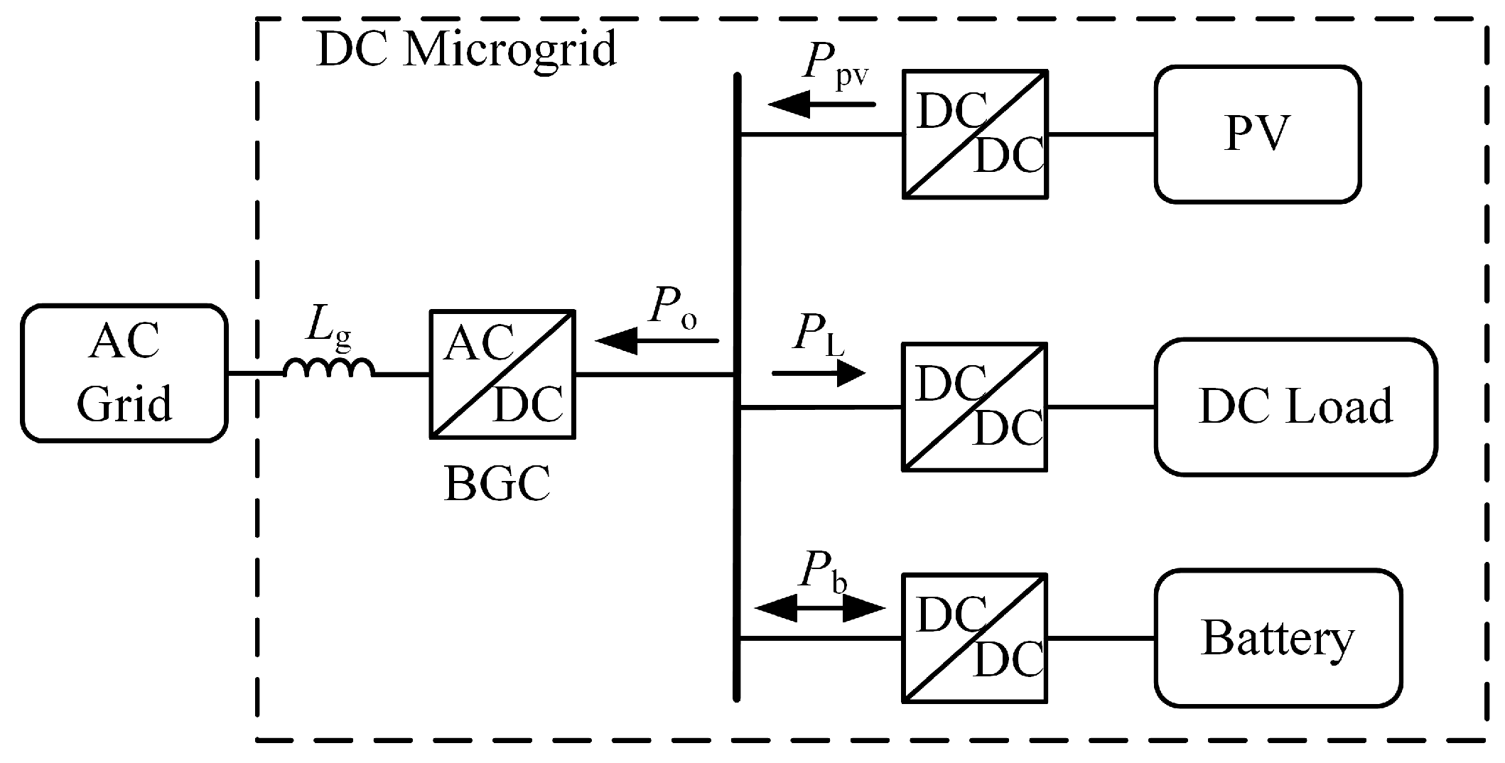
A DC microgrid configuration with BGC is shown in
Figure 1, which mainly consists of photovoltaic (PV), energy storage, DC load, and BGC, and is connected to the AC grid through BGC. By controlling the BGC, power can flow in both directions between the DC microgrid and the AC grid. The PV adopts maximum power point tracking (MPPT) technology, the energy storage adopts voltage-current double closed-loop control of the DC bus voltage, and the DC load adopts constant power control.
Ppv,
PL,
Pb, and
Po are the active power of PV, DC load, energy storage, and BGC, respectively.
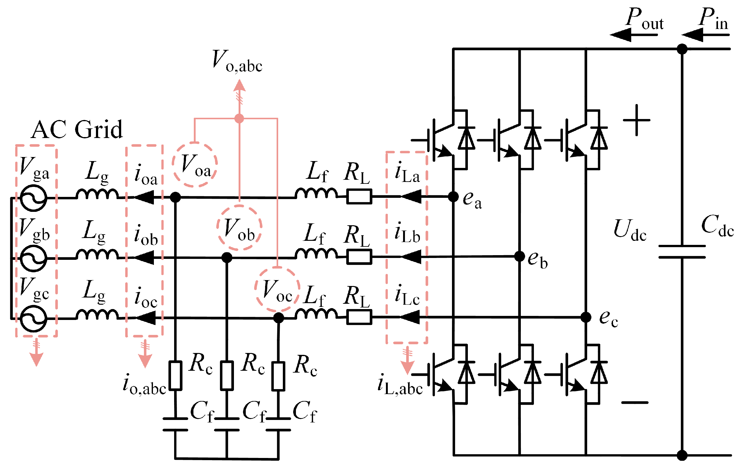
Figure 2 shows the BGC topology, where
Udc is the DC bus voltage, and
Cdc is the parallel capacitance on the DC microgrid bus.
Lf and
Cf are the BGC output filter inductance and filter capacitance,
RL and
Rc are the parasitic resistances of the filter inductance and the filter capacitance, and
Lg is the equivalent impedance of the grid.
ea,
eb, and
ec are the three-phase voltages of the midpoint of the bridge arm of the converter,
iL,abc and
io,abc are the three-phase current of the AC side inductor and the BGC output three-phase current,
Vo,abc and
Vg,abc are the three-phase voltage at the two ends of the BGC output capacitor and the three-phase voltage of the grid, respectively.
3. Proposed Inertia Enhancement Strategy
For the stability problem of the DC side of the VSG, the existing strategy utilizes the DC voltage as well as its rate of change to control the active power reference value of the VSG in order to enhance the stability of the DC side. The proposed strategy improves the VSG strategy by utilizing the dynamic characteristics of the DC capacitor, and the DC voltage acts directly on the virtual frequency to ensure the stability of the DC side voltage.
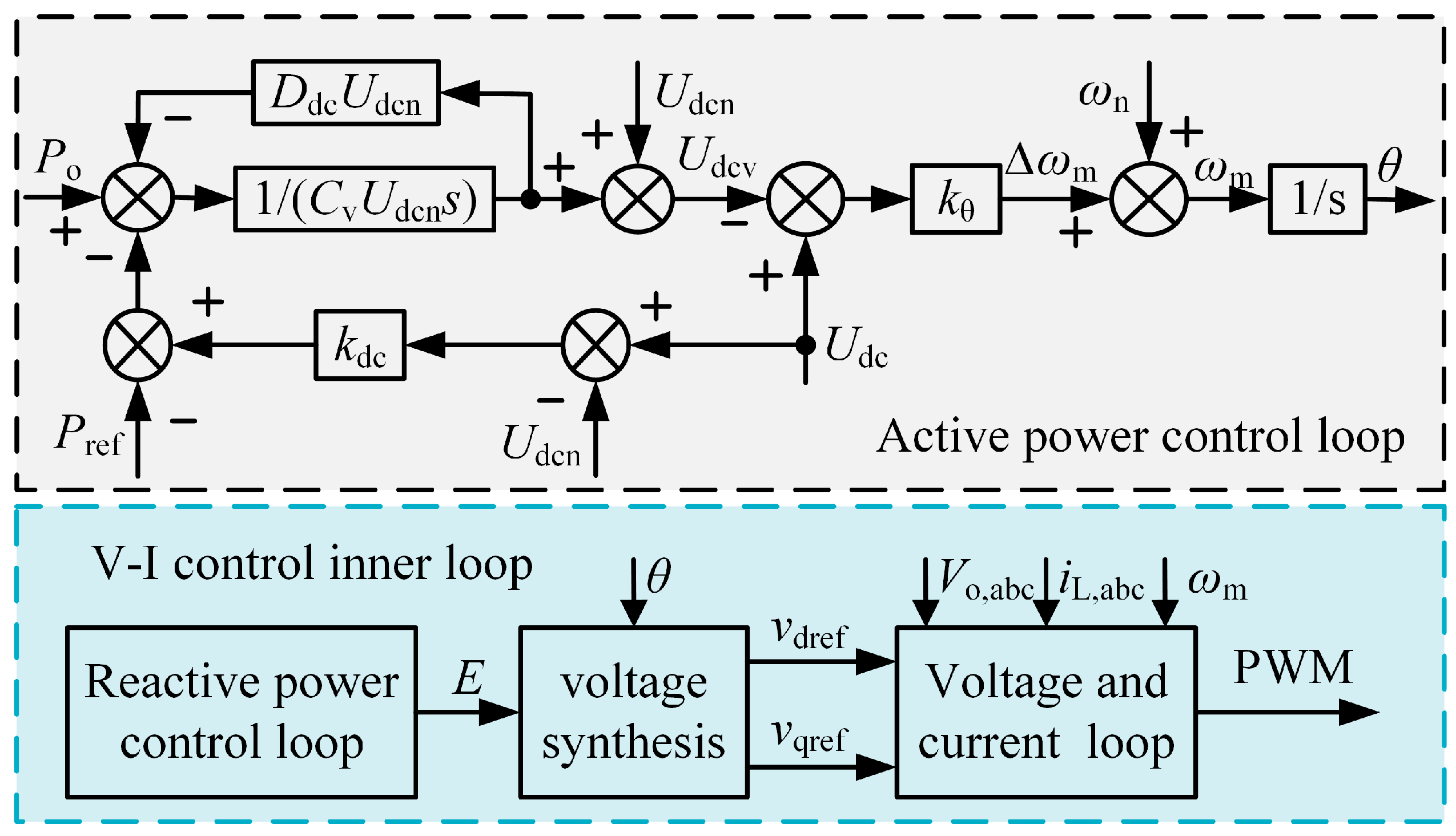
The overall block diagram of the proposed strategy is shown in
Figure 3, which mainly includes an active power control loop and a reactive power control loop. The reactive power control loop is the same as the conventional VSG strategy. The active power control loop consists of a proportional and a virtual capacitor loop.
3.1. Proportional Loop
The active power control equation for the VSG strategy can be expressed as
where
J is the virtual rotational inertia,
Pref is the power reference value,
Dac is the VSG damping coefficient, and
ωm and
ωn are the virtual and rated angular frequency of the VSG, respectively.
Neglect the damping in the VSG and compare it with the dynamic characteristic equation of the DC capacitor, as follows:
where
Pin and
Pout are the DC capacitor input and output active power. From (2), we can see that the dynamic characteristics of the DC capacitor are similar to the active power equation of the VSG in form. Citing the idea in [
17], we construct a proportional relationship for the DC voltage and virtual angular frequency, which can be expressed as
where ∆
ωm is the deviation of the virtual angular frequency with the rated angular frequency,
kθ is the proportional factor, and
Udcref is the DC voltage reference value.
3.2. Virtual Capacitor Loop
The transfer of energy from the DC side to the AC side is taken as the positive direction, and the active power control equation for the virtual capacitor (VC) strategy can be expressed as
where
Cv is the virtual capacitance,
D is the damping coefficient, and
Udcv and
Udcn are the virtual capacitance voltage and the DC nominal voltage.
To enhance the inertia on the DC side, the virtual capacitor voltage
Udcv is then used as the DC voltage reference value
Udcref, which realizes the improvement of the VSG strategy. Finally, DC voltage-power droop control is added to the active power control loop. Substituting (3) into (4) yields
where
kdc is the DC voltage-power droop coefficient. According to (5), we can see that the proposed strategy not only enhances the inertia of the AC and DC sides but also provides AC and DC damping effects. Among them, the inertia level and damping effect on the AC side are improved through the AC terms
and
, while those on the DC side are improved through the DC terms
and
.
Observing the active power control structure of the proposed strategy, we can know that the proposed strategy is highly similar to the VSG strategy in terms of structure, with the addition of only one proportional loop. Compared with the existing inertial strategy, the proposed strategy does not use differentiators, and the fluctuation of DC voltage can directly affect the value of the virtual frequency; the response speed to the change of DC voltage is much faster than the existing strategy. Therefore, the proposed strategy can provide a stronger DC voltage response speed with the same AC/DC inertia and damping effects as the existing inertia strategy, and it is not affected by the high-frequency clutter introduced by the differentiator.
4. Stability Analysis
Considering that the response speed of the power outer loop in the proposed strategy is slower than that of the voltage-current control inner loop, this paper ignores the effect of the inner loop on the power loop when analyzing the power characteristics. The active power injected into the AC network through the BGC is shown as
where
E is the virtual excitation electromotive force magnitude,
Vg is the AC grid voltage magnitude,
Xg is the equivalent impedance between the BGC and the grid, and
δ is the phase angle difference between the BGC output voltage and the grid voltage. According to [
10], the small signal model of (7) can be expressed as
Therefore, the small signal model of BGC is shown in
Figure 4. The small signal closed-loop transfer function of the strategy proposed in this paper is
where
Then, according to (9), the closed-loop pole distribution is plotted under different AC virtual inertia
J, DC damping
D, and DC virtual capacitance
Cv, as shown in
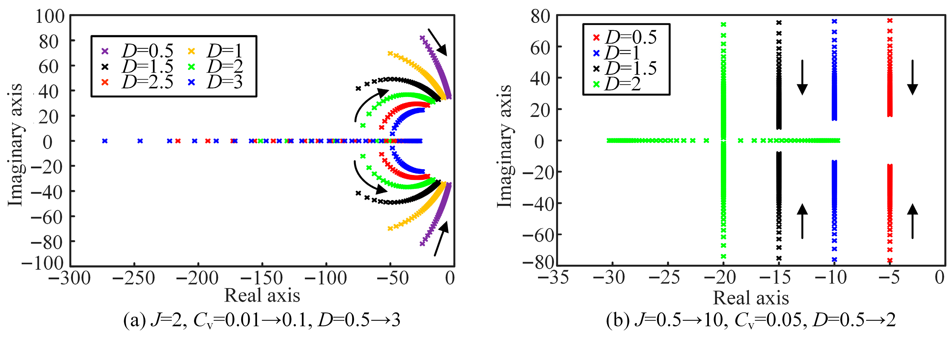
Figure 5. According to
Figure 5a, when
J and
D are constant, with the increase in virtual capacitance, the stronger the DC inertia, the pair of conjugate poles moves toward the imaginary axis, and the system dynamic response is slower.
From
Figure 5b, when
Cv and
D are unchanged, as
J increases, the closer the pair of conjugate poles is to the negative real axis, the stronger the AC inertia, the system damping is gradually enhanced, and the system active power output overshoot is smaller. When
J and
Cv are unchanged, as
D is increased, the poles gradually move away from the imaginary axis and approach the negative real axis, system damping is gradually enhanced, and system active power output overshoot is smaller.
Figure 6 shows the unit-step response of ∆
Po/∆
Pref. As we can observe from
Figure 6a, as
Cv increases, the output active power overshoot is larger, and the system damping ratio gradually becomes smaller. From
Figure 6b, as
J increases, the output active power overshoot is smaller, and the system damping ratio gradually becomes larger.
Furthermore, considering that the strategy proposed in this paper is applied to a DC microgrid, analyzing the stability of this strategy alone has limitations. Therefore, an overall analysis of the DC microgrid is necessary. In this paper, impedance modeling of each module in the DC microgrid is conducted to analyze the stability of the DC microgrid.
The output power of BGC can be expressed as
Write the state variable in (11) as the sum of the steady state quantity and the small perturbation:
Substituting (12) into (11), neglecting the quadratic perturbation term, and simplifying and performing Laplace transformation, the small-signal equation can be obtained as
According to [
24], transforming (13), the input impedance
ZBGC on the DC side of the BGC is found as
Combining (9) and (14), the input impedance of the DC side of BGC can be obtained. Based on [
25,
26], impedance modeling of each module of the system is developed. Based on impedance analysis [
27,
28], the individual modules of the DC microgrid are categorized into two types: Bus Voltage Controlled Converter (BVCC) and Bus Current Controlled Converter (BCCC). Based on the analysis of the control strategies of each module, it can be known that PV, load, and BGC belong to BCCC, while the energy storage belongs to BVCC. Therefore, the DC microgrid impedance ratio, i.e., the system open-loop transfer function
Tdc, is
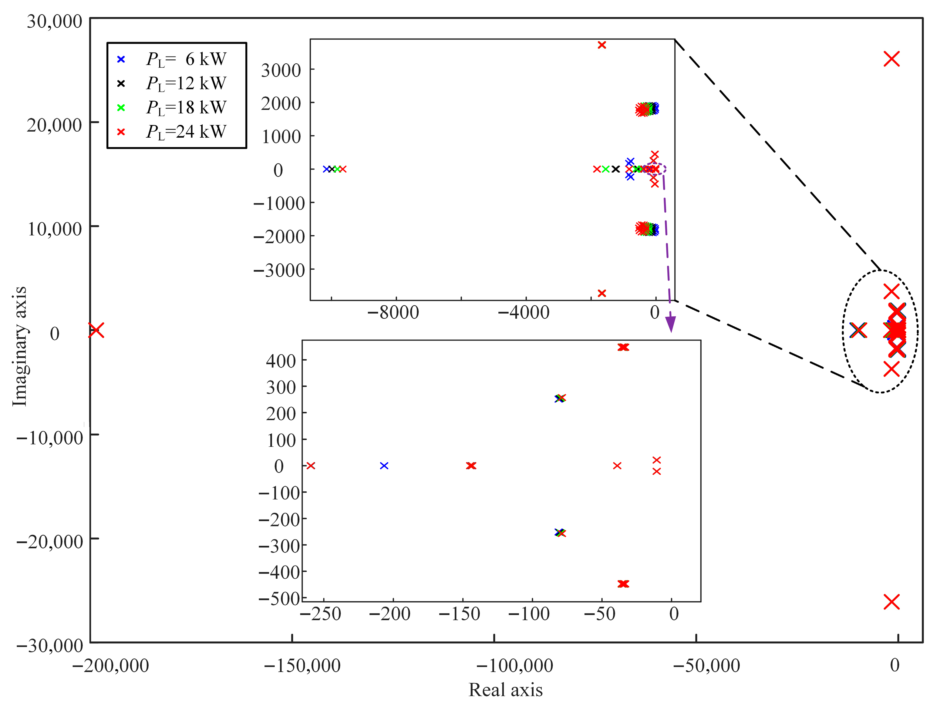
The distribution of the system’s closed-loop poles under different load powers is plotted, as shown in
Figure 7. According to
Figure 7, when the load power changes, all the closed-loop poles of the system are distributed in the left half-plane, and there are no poles in the right half-plane. Therefore, the DC microgrid system can operate stably under the strategy proposed in this paper.
5. Simulation and Experimental Verification
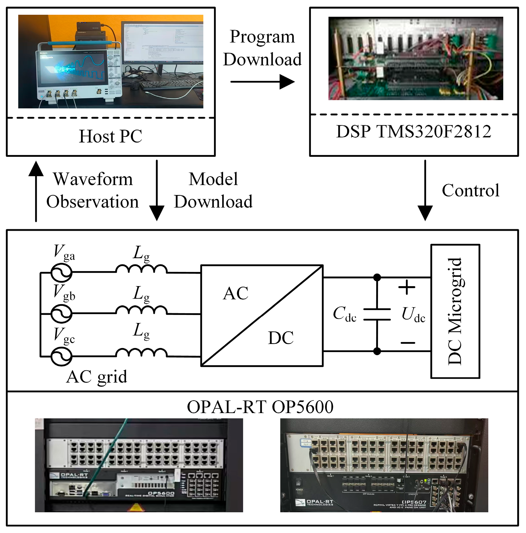
In order to verify the effectiveness of the proposed strategy, this paper builds a simulation model on MATLAB 2023a/Simulink and a semi-physical simulation on the real-time laboratory (RT-LAB), which uses the DSP28335 to control the OP5600. The experimental platform, based on the RT-LAB, is shown in
Figure 8. The system structure is shown in
Figure 1, and the rated power of PV, energy storage, BGC, and DC load are all 24 kW, all switch frequencies are 10 kHz, the rated frequency of the grid is 50 Hz, the line voltage is 380 V, and the DC voltage-power droop coefficient is 1.6 kW/V. The parameters of the proposed control strategy are shown in
Table 1.
In order to verify the inertia-enhancing ability of the proposed strategy on both AC and DC sides and the DC voltage stabilizing ability, simulated and experimental tests are carried out under AC-side and DC-side disturbances, respectively. The proposed strategy is compared with VSG control, PI control [
12], and virtual inertia control [
29] in simulation and experiment.
5.1. Simulation Verification
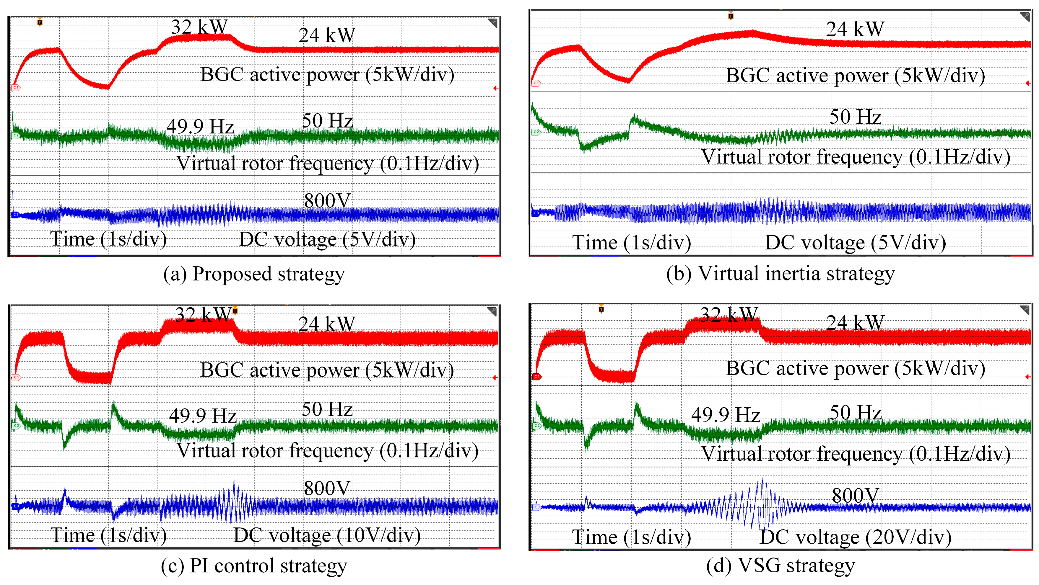
(1) Case 1: Simulation of AC side inertia enhancement test. Figure 9 shows the simulation results of DC voltage, frequency, and BGC active power when the active power reference value and the grid frequency are changed under the control of four strategies. The load is 10 kW at the beginning, and the active power reference value is set to 24 kW, which is set to 0 kW at 1 s and 24 kW at 2 s; the grid frequency decreases to 49.9 Hz at 3 s, and the grid frequency returns to 50 Hz at 4.5 s.
The simulated waveforms show that all four control methods can realize power control and increase the active power output to realize frequency support when the grid frequency is reduced.
Table 2 shows the fluctuations of DC voltage when the active power reference value and the grid frequency change in simulation. The DC voltage fluctuation under the VSG control and [
12] reach more than 30 V when the active power reference varies. The DC voltage fluctuation under the VSG control even reaches 82 V when the grid frequency varies. [
12] reduces the voltage fluctuation in comparison to the VSG control, but it also has about 30 V fluctuation. The DC voltage of [
29] fluctuates below 10 V, and there are small oscillations during grid frequency changes. However, the DC voltage fluctuation under the proposed strategy is kept below 5 V, the output active power has no obvious oscillation, and the change rate of frequency is even smaller.
(2) Case 2: Simulation of DC side inertia enhancement test. Figure 10 shows the simulation results of DC voltage and BGC active power under the control of four strategies for DC microgrid PV light intensity and load variation. The strategies are tested to see whether they have a stabilizing effect on the DC voltage through the DC side disturbances.
The active power reference value is set to 24 kW, the load power is 15 kW, and the PV output is 24 kW. The PV light intensity is reduced at 1 s to make the PV output less than 15 kW. At this time, since the energy storage is rated at 24 kW, the DC voltage will not be able to maintain stability if the BGC active power is kept constant at 24 kW. From the DC voltage and active power waveforms under VSG control, we can observe that when there is an active power deficit in the system, the DC voltage under the VSG strategy continues to drop to 400 V, and there is a large oscillation in the BGC output active power. So, we can see how much the VSG strategy affects the degree of voltage stability on the DC side.
In the proposed strategy, Refs. [
12,
29] can stabilize the DC voltage by adjusting the active power of the BGC according to the power deficit of the DC microgrid.
Table 3 demonstrates the DC voltage fluctuations as the DC microgrid load and PV output power vary in simulation. The proposed strategy and [
29] quickly stabilize the DC voltage, although there are DC voltage fluctuations of nearly 50 V and 100 V, respectively. The DC voltage of [
12] appears to fluctuate for 0.4 s, with a peak value of 50 V. At 2 s, the DC load power rises to 20 kW, and the DC microgrid power deficit widens further. The proposed strategy and [
29] quickly stabilize the DC voltage, whereas [
12] shows a large fluctuation that lasts for 0.4 s and peaks at 108 V. In summary, compared to the VSG strategy [
12,
29], the proposed strategy can adjust the BGC active power more smoothly when there is an active power deficit in the system.
5.2. Experimental Verification
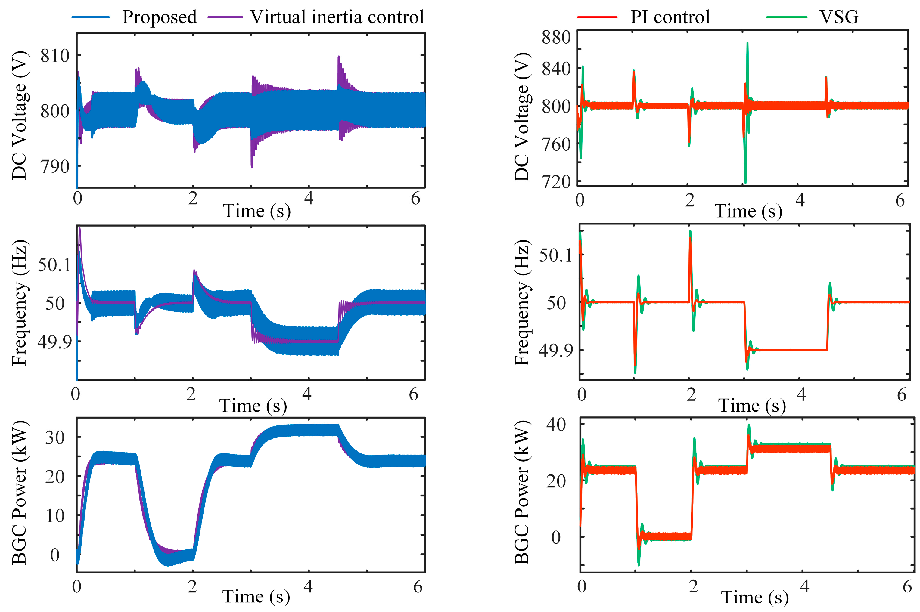
(1) Case 1: AC-side inertia enhancement test experiment. Figure 11 shows the experimental results under Case 1, where the experimental parameters and AC-side perturbation settings are the same as the simulation.
Figure 11a–d shows the experimental waveforms under the proposed strategy, PI control strategy [
12], Virtual inertia strategy [
29], and the VSG strategy, respectively.
The experimental waveforms show that all four control methods can achieve power control and inertia improvement on the AC side.
Table 4 shows the fluctuations of DC voltage when the active power reference value and the grid frequency change in the experiment. The DC voltage fluctuation is kept below 10 V under the proposed strategy and [
29]; Ref. [
12] and the VSG strategy show some amplitude of voltage oscillation, with oscillation peaks of 30 V and 70 V, respectively.
Therefore, compared with the VSG control [
12,
29], the proposed strategy effectively slows down the DC voltage and frequency variations and ensures the stability of the system control.
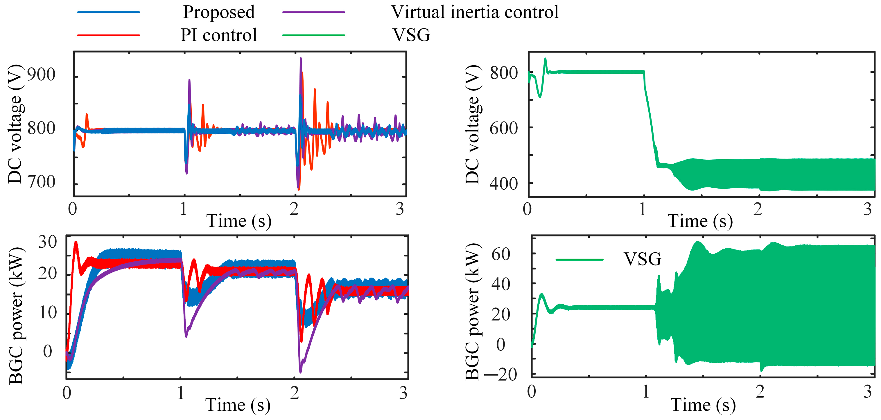
(2) Case 2: DC-side inertia enhancement test experiment. Figure 12 shows the experimental results under case 2, where the experimental parameters and DC side disturbance settings are consistent with the simulation.
Figure 12a–d shows the experimental waveforms under the proposed strategy, PI control strategy [
12], Virtual inertia strategy [
29], and the VSG strategy, respectively.
Table 5 demonstrates the DC voltage fluctuations as the DC microgrid load and PV output power vary in the experiment.
At 1 s, according to
Figure 12d, we can see that the VSG strategy does not have the ability to keep the DC voltage stable and even affects the DC voltage stabilization. Once the energy storage is unable to stabilize the DC voltage, it will lead to system collapse, the DC voltage will continue to drop to 400 V, and the BGC output power will oscillate.
According to
Figure 12c, we can observe that the DC voltage of [
12] fluctuates with a peak value of 70 V at 1 s and gradually stabilizes. At 2 s, the DC load power rises to 20 kW, the active power deficit of the DC microgrid further expands, and the DC voltage of [
12] fluctuates more, with a peak value of 116 V, but still gradually stabilizes. It can be seen that the ability of PI control in [
12] to steady the DC voltage is not strong, and when the active power of the system has a large fluctuation, the response speed of [
12] is slow, it cannot stabilize the DC voltage quickly, and the DC voltage fluctuates greatly.
According to
Figure 12b, at 1 s and 2 s perturbations, the DC voltage of [
29] shows some oscillations with fluctuation amplitudes of 68 V and 100 V, respectively. According to
Figure 12a, we can observe that the DC voltage of the proposed strategy fluctuates 30 V under 1 s and 2 s perturbations and remains stable quickly. In summary, the proposed strategy can better stabilize the DC voltage, effectively improve the inertia level of the DC side, and control with higher stability.
