1. Introduction
Silicon carbide (SiC) has 10 times the electric field strength, 3 times the thermal conductivity, and 3 times the energy gap compared to Silicon. The new multilevel converter based on SiC power devices has better control performance, higher efficiency, and smaller volume [
1,
2,
3]. Compared with other medium and high-voltage multilevel topologies, such as modular multilevel converters (MMC) and neutral point clamped multilevel converters (NPC), hybrid multilevel converters (HCC) use fewer switching devices and have better control performance and higher efficiency [
4]. Combining SiC devices, it is expected to build medium and high-voltage converters with high power density and high efficiency [
5,
6,
7,
8].
Current research on HCC mainly focuses on the topology and control strategies, aiming to achieve balanced capacitor voltages and reduce voltage fluctuations to enhance system efficiency and reduce output harmonic. Reference [
9] proposed a unified specific harmonic elimination pulse width modulation for HCC, making harmonic elimination control more flexible and improving control performance. Reference [
10] introduced an open-loop control method based on the injection of third-order common-mode harmonic voltages, which can significantly reduce the voltage fluctuations of DC bus capacitors, increase voltage utilization, and lower output harmonic content. However, for medium-voltage multilevel converters operating for long periods, the primary condition for ensuring the reliable operation of SiC-based equipment is to achieve real-time fault monitoring and rapid protection under substantial electromagnetic-thermal coupling impacts [
11,
12].
When a SiC-based multilevel converter experiences an overcurrent fault, the propagation speed of this fault is fast, and the time required for the circuit breaker to isolate the fault.
When an overcurrent fault occurs in a SiC-based multilevel converter, the fault propagates rapidly. As a result, the time required for fault isolation using a circuit breaker is relatively long (typically at the millisecond level [
13]). Therefore, a more effective solution is to utilize the converter’s inherent protection functions to achieve fault blocking and clearance. Reference [
14] proposed replacing one-third of the half-bridge sub-modules with full-bridge sub-modules for MMCs to achieve the ability to block short-circuit faults. For short-circuit faults that occur during the operation of power devices, short-circuit fault detection and protection circuits integrated into the driver are usually employed to ad-dress them. In the case of the power device is in an open-circuit fault state, software can be used to detect and locate the faulty device. In [
15], the average value of the three-phase AC current was extracted as a fault feature, and a genetic algorithm was employed to locate the faulty device. Reference [
16] proposed a fault diagnosis method based on state observers and a new fault-tolerant operation method to achieve reliable operation under device open-circuit faults.
Most of the literature mentioned above focuses on a single type of fault and has problems such as complex algorithm implementation and increased hardware costs. This paper proposes a multilevel fault monitoring and protection method for medium-voltage all-SiC-based hybrid multilevel converters. It can monitor various faults that threaten the regular operation of converter and provide multilevel response protection through software control/hardware triggering, ensuring the safe operation of medium and high-voltage converters. The remaining content of this paper is structured as follows: In
Section 2, typical faults during the operation of medium-voltage converters are analyzed, and their severity and the characteristic quantities that need to be monitored are clarified. Based on typical fault types,
Section 3 designs a set of hardware and software protection systems, and provides a detailed explanation of the hardware protection design and the software protection control algorithms. In
Section 4, the effectiveness of the proposed multilevel fault monitoring and protection method is verified through experiments. The experimental results show that the system can effectively protect system safety in the face of various faults and improve the operational reliability of medium-voltage converters.
2. Analysis of Typical Faults and Extraction of Characteristic Quantities
The common fault types of medium-voltage multilevel converters include overcurrent, overvoltage, overtemperature, etc. [
17,
18,
19]. As shown in
Table 1, the classification of typical faults is described. Due to the different causes of faults, the hazard levels of faults are also different. Therefore, this paper adopts different protection methods for various types of faults caused by various causes. A multilevel fault protection method combining software and hardware is adopted for faults with high hazard levels.
Overcurrent fault is the most harmful fault. When the controller malfunctions, causing the device to mislead through, or when there is a short circuit between output phases, it will lead to an overcurrent of the device. At this point, the current through the device increases sharply. If the device cannot be turned off in time, overcurrent burning out is risky. Because this short-circuit current has the characteristics of a short rise time and a fast current growth rate, the method of measuring the on-voltage of the device is usually adopted to monitor this fault. Moreover, this fault usually must be cleared within a relatively short time. Therefore, rapid protection should be provided at the hardware level first. Then, the fault signal should be reported to the control software, which will block the drive signal to other switching devices to protect the inverter.
When the output current exceeds the preset rated value, the converter can still maintain a normal output state. However, working in this state for a long time will increase the converter’s loss, thereby causing an overtemperature fault. This fault should be monitored by collecting the output current. When the output current exceeds the preset rated value, the software should promptly trigger an alarm to remind the converter to operate at a reduced capacity or shut down.
Overvoltage fault refers to the overvoltage caused by the fluctuation of capacitor voltage when the converter is operating under harsh conditions. Monitoring this fault requires monitoring the capacitor voltage. However, the actual withstand voltage of the capacitor in the converter is usually lower than the rated value of the capacitor voltage. Capacitor overvoltage caused by fluctuations can be considered a software alarm. When the power supply or controller malfunctions, causing the capacitor to overcharge due to incorrect operation, rapid hardware protection should be taken at this time. Meanwhile, at the software level, the drive signal should be disconnected, and the capacitor should release the residual charge through the resistor.
Overheating faults often occur during the long-term operation of the converter. The accumulation of losses of the switching devices causes severe heating of the devices. If switching devices operate at excessively high temperatures for a long time, it may accelerate the aging of the devices. Meanwhile, excessively high temperatures can also cause damage to the devices and lead to overcurrent. The typical characteristic quantity of this fault is temperature. Since SiC devices can operate at a specific temperature, software alarms are adopted at medium and high temperatures. Overcurrent faults can also cause a sharp temperature rise. Under this working condition, hardware rapid protection should also be adopted.
In conclusion, due to the different types of faults, some faults require rapid protection through the collaboration of software and hardware to ensure the safety of the devices. At the same time, some faults do not cause damage to the converter in a short period when they occur, but if they persist for a long time without alarm or protection, they will also threaten the safe operation of the converter. Therefore, at the software level, it is also necessary to collect key data of the converter for monitoring to ensure its reliable operation.
3. Multilevel Fault Monitoring and Protection Methods
The second section analyzes the common fault types of medium and high-voltage multilevel converters. Among them, output short circuit or direct connection of devices, severe overheating of modules, or rapid overvoltage of capacitors can all seriously endanger the safe operation of the converter. At the same time, there are also faults such as excessive output current, overheating of the module, and excessive capacitor voltage, which require software monitoring and alarm. Based on this, this paper proposes a multilevel fault monitoring and protection method that can be applied to medium and high voltage all-SiC hybrid multilevel converters. This part clarifies the software/hardware coordinated monitoring and protection design [
20,
21].
3.1. Hardware Protection Design
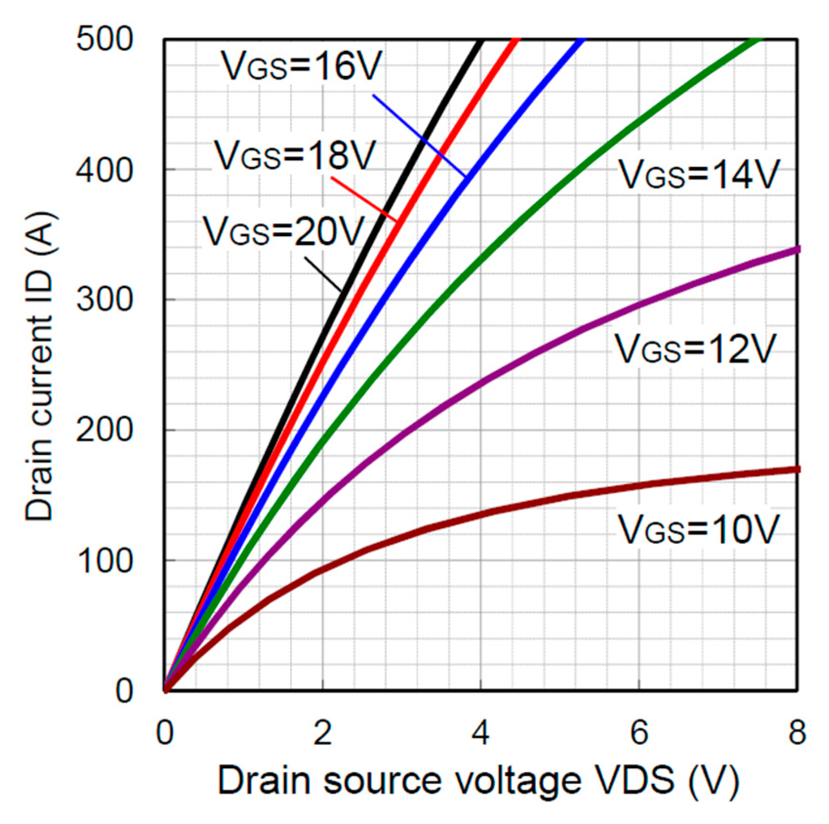
As mentioned above, fatal faults require rapid hardware protection. Therefore, in this section, an intelligent gate driver is designed for the 1700V/250A SiC MOSFET (model BSM250D17P2E004, manufactured by ROHM Semiconductor in Kyoto, Japan), and its characteristics are shown in
Table 2 and
Figure A1. This device integrates rapid and high-precision hardware protection for device overcurrent/overtemperature/overvoltage. Faults can be identified, and turn-off protection can be achieved within a time scale of microseconds, thereby completing the protection at the device layer.
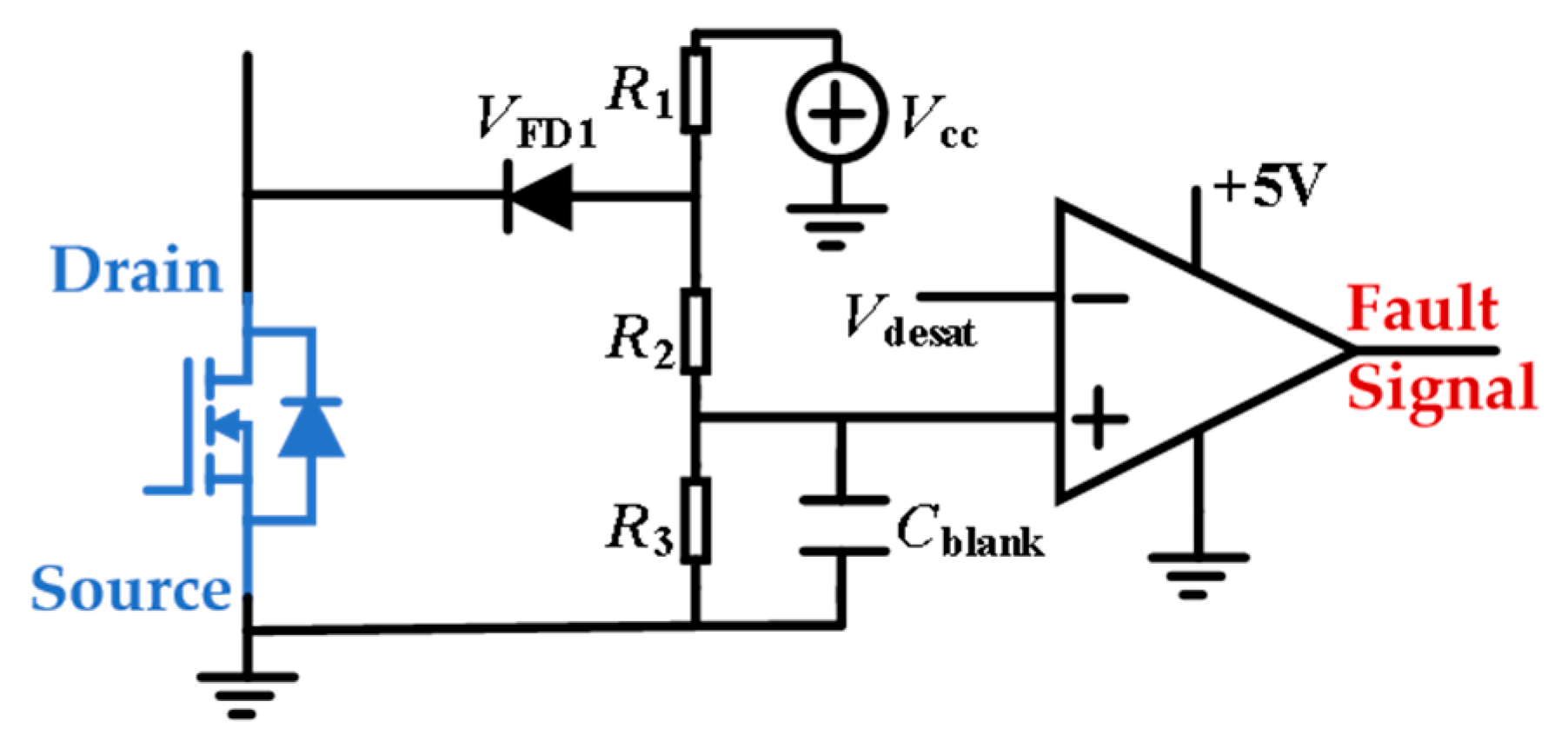
Due to the small area of SiC chips, high current density, and high sensitivity of parasitic parameters, the device’s temperature rises sharply during the short circuit. Therefore, a protection circuit design with high sensitivity and anti-interference ability is required. DESAT is the most mature short-circuit protection circuit, with its nomenclature originating from the term “desaturation”. The DESAT circuit samples the sum of the conduction voltages of the anti-parallel diode and the device, providing rapid protection for the device in case of a short-circuit fault. Based on the principle of basic desaturation protection, this paper proposes a DESAT with parameter optimization design for overcurrent protection of the device.
The schematic diagram of DESAT is shown in
Figure 1. Its basic principle is as follows: When the device operates normally, the voltage between its drain and source is relatively low, the diode conducts, and the voltage across the blank-eliminating capacitor, C
blank, is relatively low. When a short circuit occurs in the device, the current in the device rises sharply, the voltage between the drain and source increases rapidly, and the C
blank voltage rises accordingly. When it exceeds the preset voltage, V
desat, the comparator outputs a fault signal, thereby turning off the device. The threshold detection voltage V
ds_on for activating the DESAT circuit can be calculated by Equation (1):
Among them,
Vds_on is the conduction voltage during a short circuit, and the appropriate short-circuit protection voltage value can be selected by adjusting the values of
R2 and
R3.
VFD1 is the voltage of the blocking diode. Since maintaining a low parasitic parameter of the blocking diode benefits the system’s anti-interference performance, it can reduce the interference of high dv/dt generated by a faster switching speed to the DESAT, thereby causing false triggering. Based on the above analysis, this paper adopts a Schottky diode with a blocking voltage of 2 kV. Its model is RRGP02-20E-E3/73, and the junction capacitance is only 3 pF. Although the parasitic parameters on the Schottky diode are already relatively small, there is still a blank-vanishing time,
tblank, for the protection delay, which can be expressed by Equation (2).
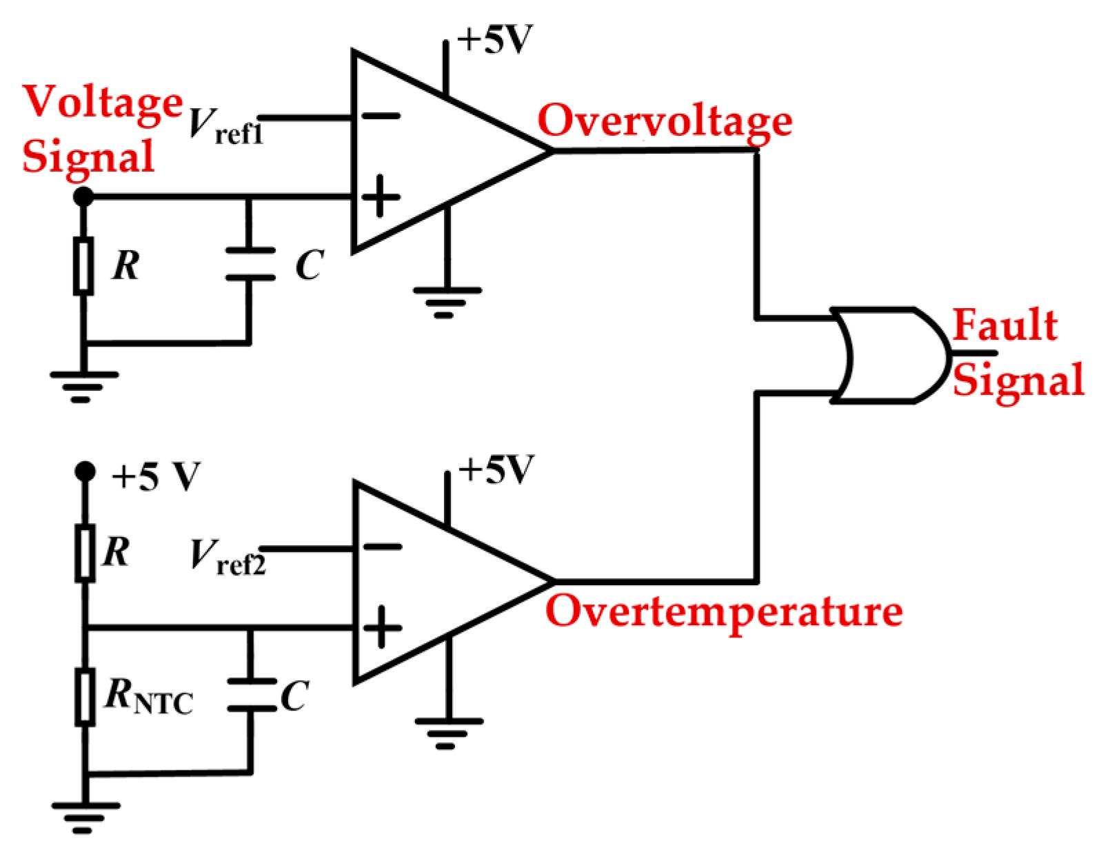
Meanwhile, the drive device also integrates hardware protection circuits for overtemperature and overvoltage of the device. The schematic diagram is shown in
Figure 2. After the Hall voltage sensor detects the device voltage, a voltage signal is generated through the signal conditioning circuit. Then, the analog signal is compared with the comparator’s reference voltage. Once the signal exceeds the reference voltage, the comparator outputs a fault signal, the drive signal becomes low, and the power device turns off. The overtemperature protection circuit is similar to the overvoltage protection circuit. The driving device collects the resistance voltage from the device’s thermistor. The higher the temperature, the lower the voltage. The comparator outputs a fault signal when the voltage is lower than the reference voltage. Therefore, regardless of whether overvoltage or overheating faults occur, the device immediately receives the fault signal and generates a turn-off signal.
3.2. Software Protection Design
At the software level, to provide detection and protection for the converter, it is necessary to extract key parameters of the converter, such as capacitor voltage, output current, device temperature, etc. This paper designs a controller combining DSP and FPGA. The driving signal is transmitted to the device through optical fiber, and the fault signal generated at the hardware level is also transmitted to the controller through optical fiber. The temperature, capacitor voltage, and output current signals collected by the sensor are transmitted to the controller for analysis.
Figure 3 presents the overall control structure diagram of the central control system using DSP and FPGA. The selected DSP is the TMS320F28377D (manufactured by Texas Instruments, Dallas, TX, USA), and the FPGA is the Altera Cyclone IV EP4CE40F29C8N (manufactured by Intel, Santa Clara, CA, USA). In the experimental setup, the DSP handles slower control tasks, such as carrier generation and feature extraction, with an execution frequency of 50 kHz, while the FPGA is responsible for high-speed tasks including the generation of driving signals, with an execution frequency of 50 MHz.
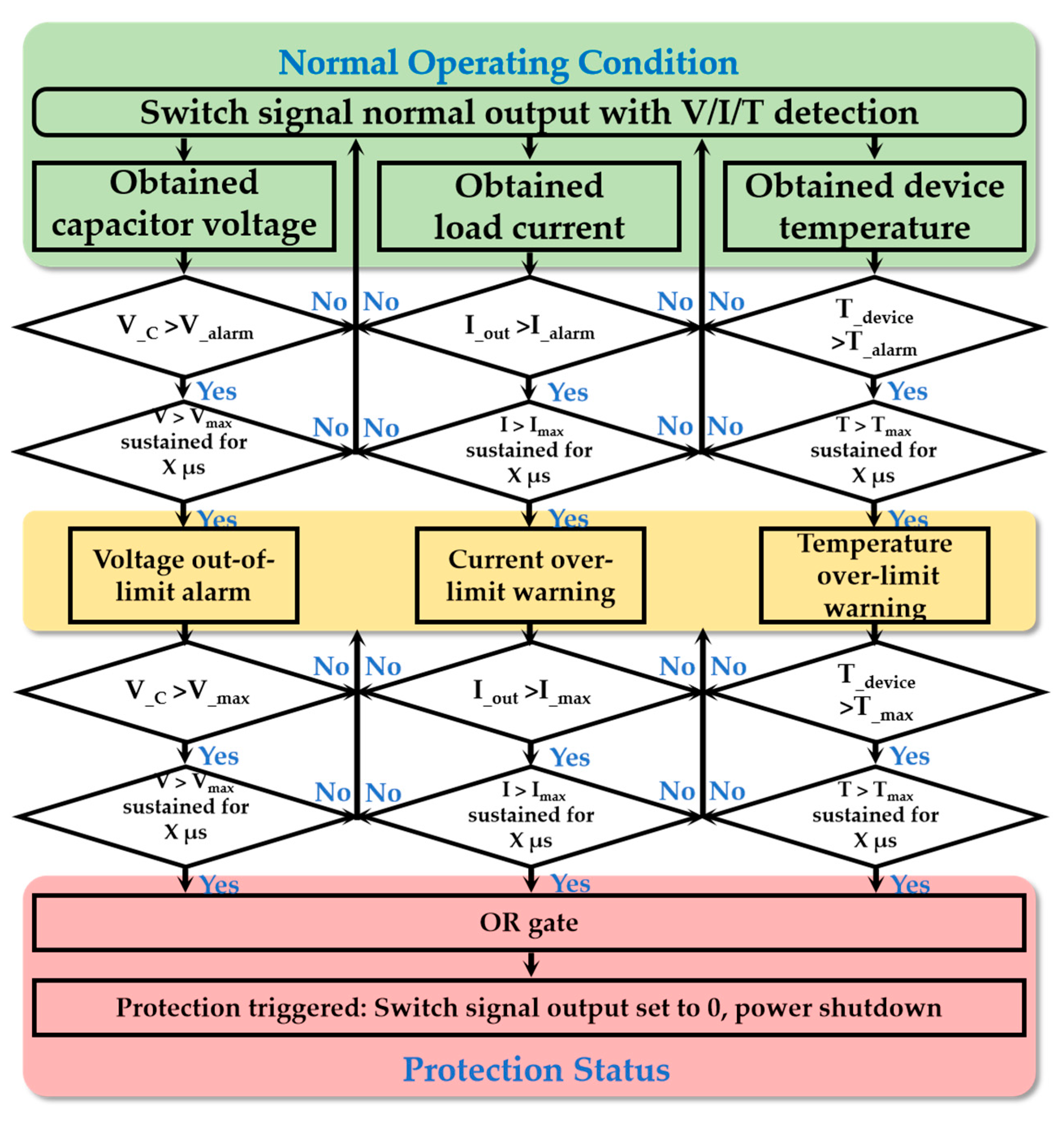
The temperature, capacitance voltage and output current of the devices in the control system can be monitored using high-precision sensors at the software level. Based on this monitoring value, rapid detection and protection of faults such as excessive system output current, system overheating, and capacitor fluctuation overvoltage can be achieved. The program flowchart for alarm and protection at the software level is shown in
Figure 4.
When the converter operates normally, the switch signal is usually output, and the system voltage/current/temperature is commonly detected simultaneously. The program will enter the timing stage when the capacitor voltage, output current, and device temperature exceed the alarm value. If they cannot remain above the alarm value for a period of time, they will be regarded as disturbances during the sensor’s transmission process and will not be protected. The alarm state will be entered if it can continuously exceed the protection value by 50 μs. After the system enters the alarm state, it continues to monitor each characteristic value using the same logic described above. If it is greater than the maximum value for a period of time, the system enters the software protection state. At this time, all switch signals are output low, and the emergency stop switch is controlled to cut off the power supply.
3.3. Multilevel Fault Protection Method
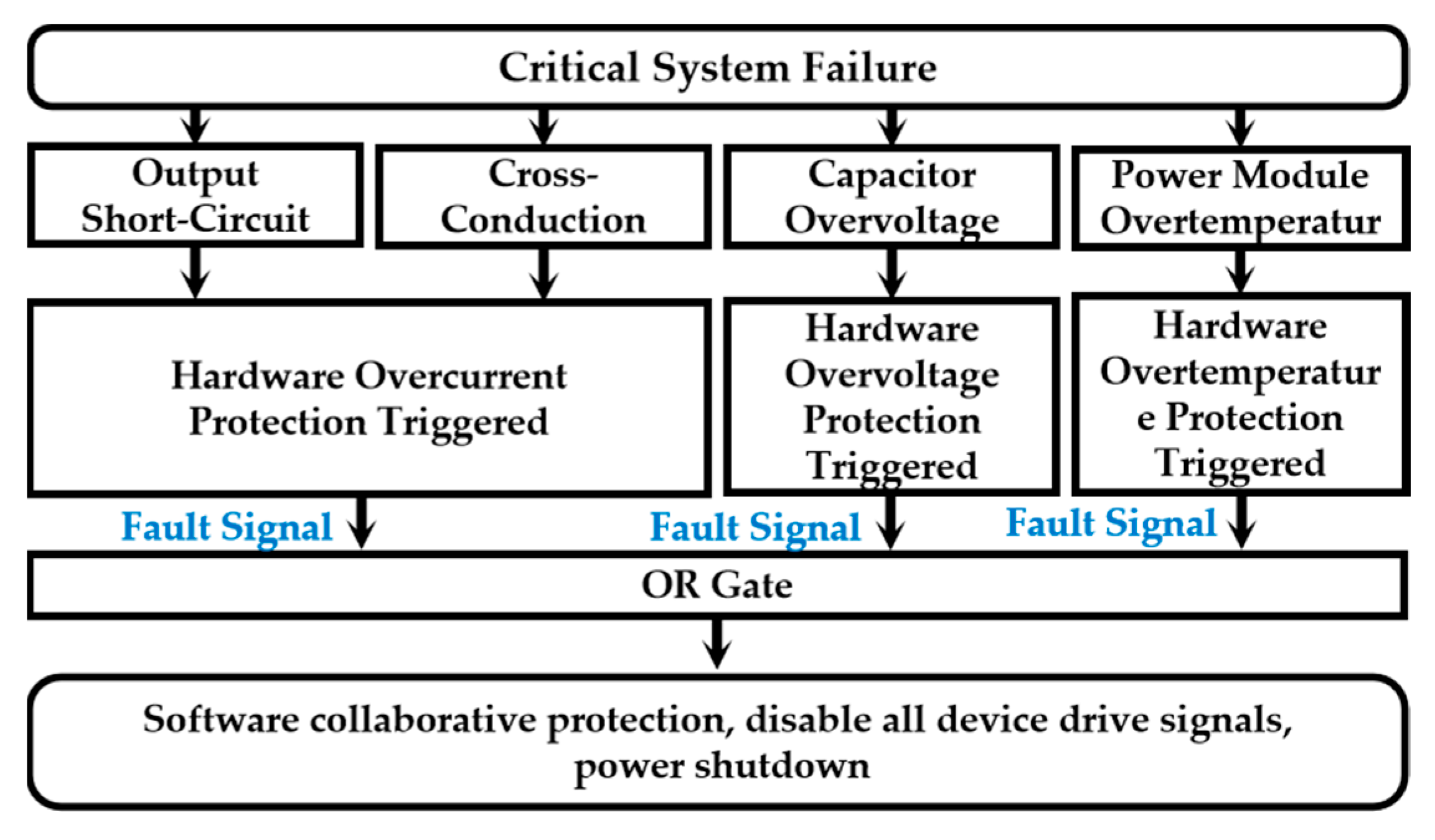
When a multilevel converter is exposed to extreme working conditions and faults such as output short circuit or direct connection of devices, severe overheating of modules, and rapid overvoltage of capacitors occur, the safety of individual devices can only be protected by hardware alone. The safety of the entire converter requires the coordination of software and hardware. Therefore, this paper proposes a multilevel protection method for the coordinated cooperation of software and hardware. When facing extreme working conditions, the specific protection process is shown in
Figure 5.
When a high-risk fault occurs, the corresponding hardware protection is triggered first. As mentioned above, the hardware design can only protect a single device. However, in a multilevel converter, a fault on a single device may spread to other devices. Therefore, when the hardware protection on the device is triggered, the fault signal should be transmitted to the software simultaneously. After receiving a fault signal at the software level, the drive signals of other devices should be turned off promptly, and the power supply should be cut off to prevent the fault from spreading.
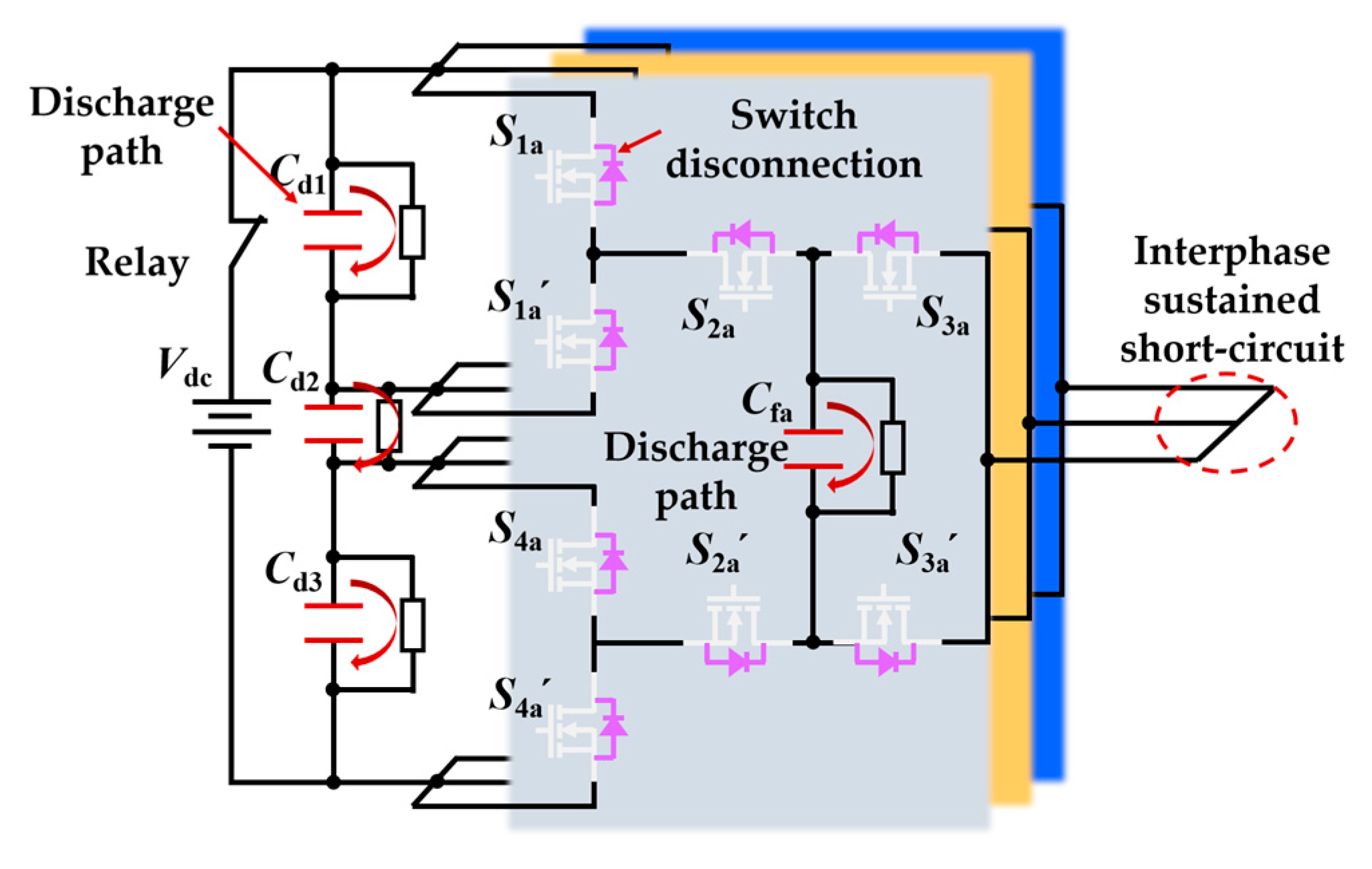
In addition, as shown in
Figure 6, after the software turns off the driving signals of each device, there are discharge resistors on each capacitor. When a continuous short-circuit fault occurs between the output phases, the system will enter the overcurrent protection state as preset. The hardware overcurrent protection is triggered first, then the drive signals of each device are turned off, and at the same time, the power supply is disconnected from the converter through relay. Afterward, each capacitor will discharge through the discharge resistor connected in parallel with it, achieving protection for the entire system and facilitating personnel to approach and clear the fault.
4. Experimental Verification
To validate the effectiveness of the proposed hardware overcurrent protection method for the power module, a dedicated module testing platform was established.
First, the power module designed in this work is introduced, with its structure and prototype shown in
Figure 7. The designed power module consists of four main components: the power supply board, driver board, SiC power module, and heatsink. The power supply board includes a voltage sensor and two power supply units. The voltage sensor monitors the voltage across the power module, while the power supply units provide power to the driver board. The driver board contains the gate drivers that control the upper and lower power devices in the power module. The SiC power module adopts a half-bridge structure consisting of two power devices, S
1 and S
2. The heatsink, after being coated with thermal grease, is attached directly to the back of the power module to ensure efficient heat dissipation.
The constructed module testing platform is illustrated in
Figure 8. The drive control signals of the module are generated by the FPGA. V
dc represents the bus voltage.
Cdc is the DC-link capacitor, which adopts model CBB131 manufactured by Jianghai in Nantong, China, with a rated voltage of 1500 V and a capacitance of 330 μF.
Cdec is the decoupling capacitor, which is used to reduce voltage overshoot during switching. In this work, the designed decoupling network consists of two types of capacitors: the film capacitor and the multilayer ceramic capacitor (MLCC). The film capacitor used is model MKP386M410200JT5 by Vishay, rated at 2000 V with a capacitance of 0.1 μF. The MLCC used is model C2220X443KGRLCAUTO by KEMET in Fort Lauderdale, FL, USA, also rated at 2000 V with a capacitance of 0.044 μF. V
GS_S1 is the gate drive signal of the upper switch, which is normally off.
VGS_S2 is the gate drive signal of the lower switch.
ID indicates the current through the lower switch
S1, and V
DS is the voltage across
S2.
Ls represents a custom-wound air-core short-circuit inductor, which is used to short
S1 and generate a large transient current. Meanwhile, it allows control of the current rise rate to prevent device damage. The inductance value of is approximately 2 μH.
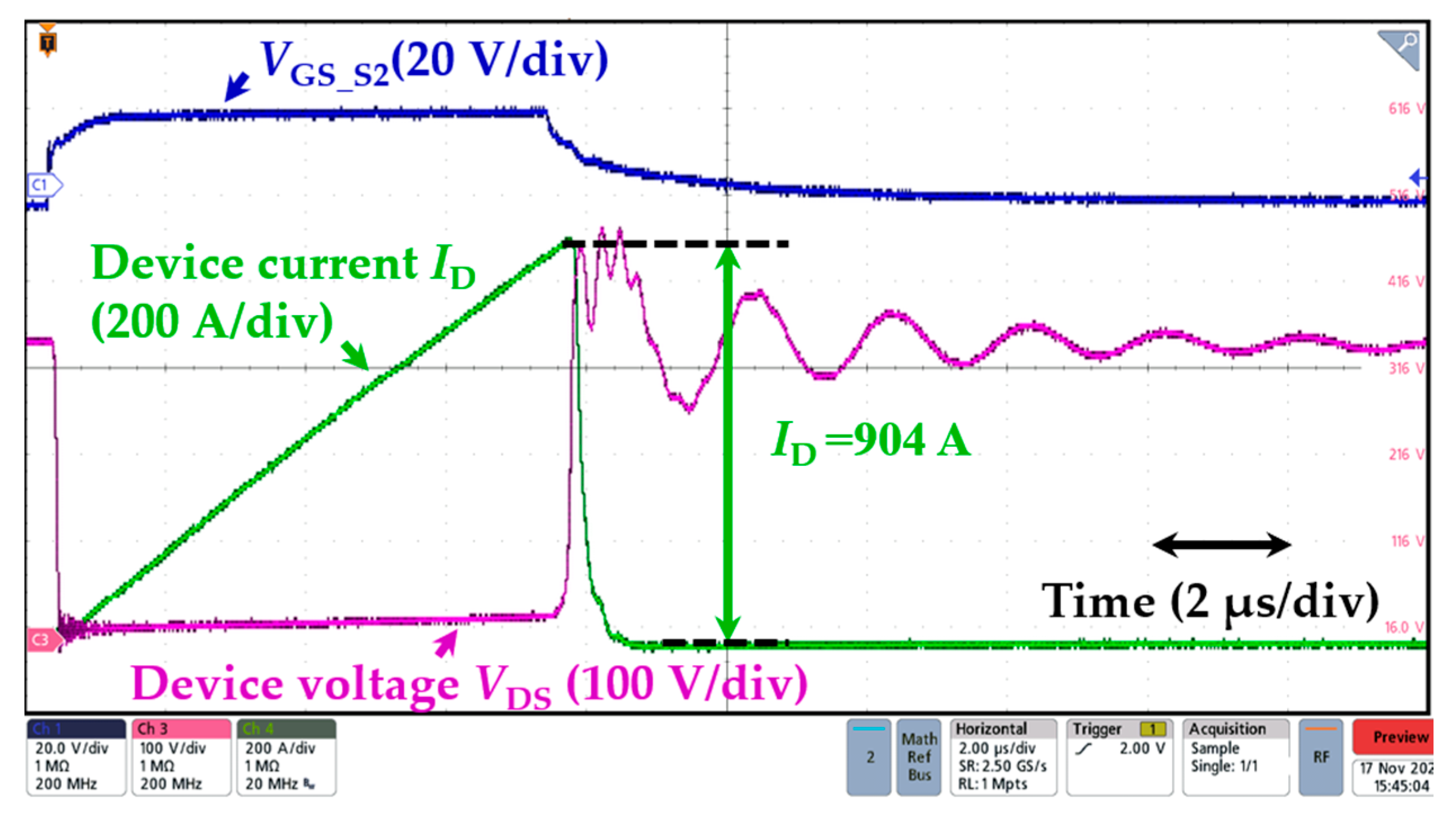
Figure 9 shows the test results of hardware short-circuit protection. The FPGA sends a drive signal with a fixed time width of 10 μs. After the device is turned on, the current rises rapidly and reaches 904 A within 7 μs, triggering the overcurrent hardware protection. The experimental results show that the designed DESAT circuit works normally and can protect the device overcurrent in time.
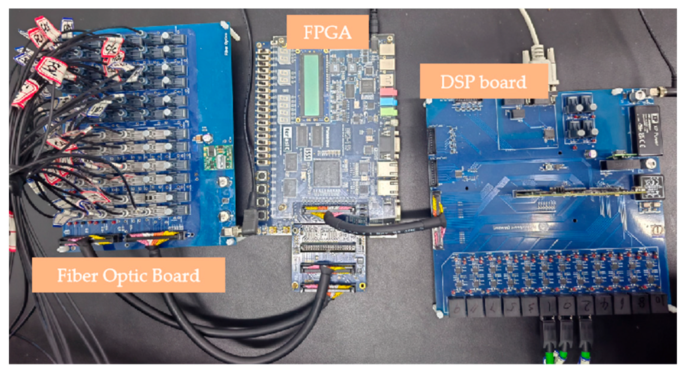
To verify the effectiveness of the proposed multi-level fault monitoring and protection method, a 3 kV/500 kVA three-phase HCC experimental prototype was built. The converter is based on the power module described earlier. The prototype of the controller, integrating DSP and FPGA, is shown in
Figure 10. The overall view of the experimental system is shown in
Figure 11, and the system parameters are listed in
Table 3.
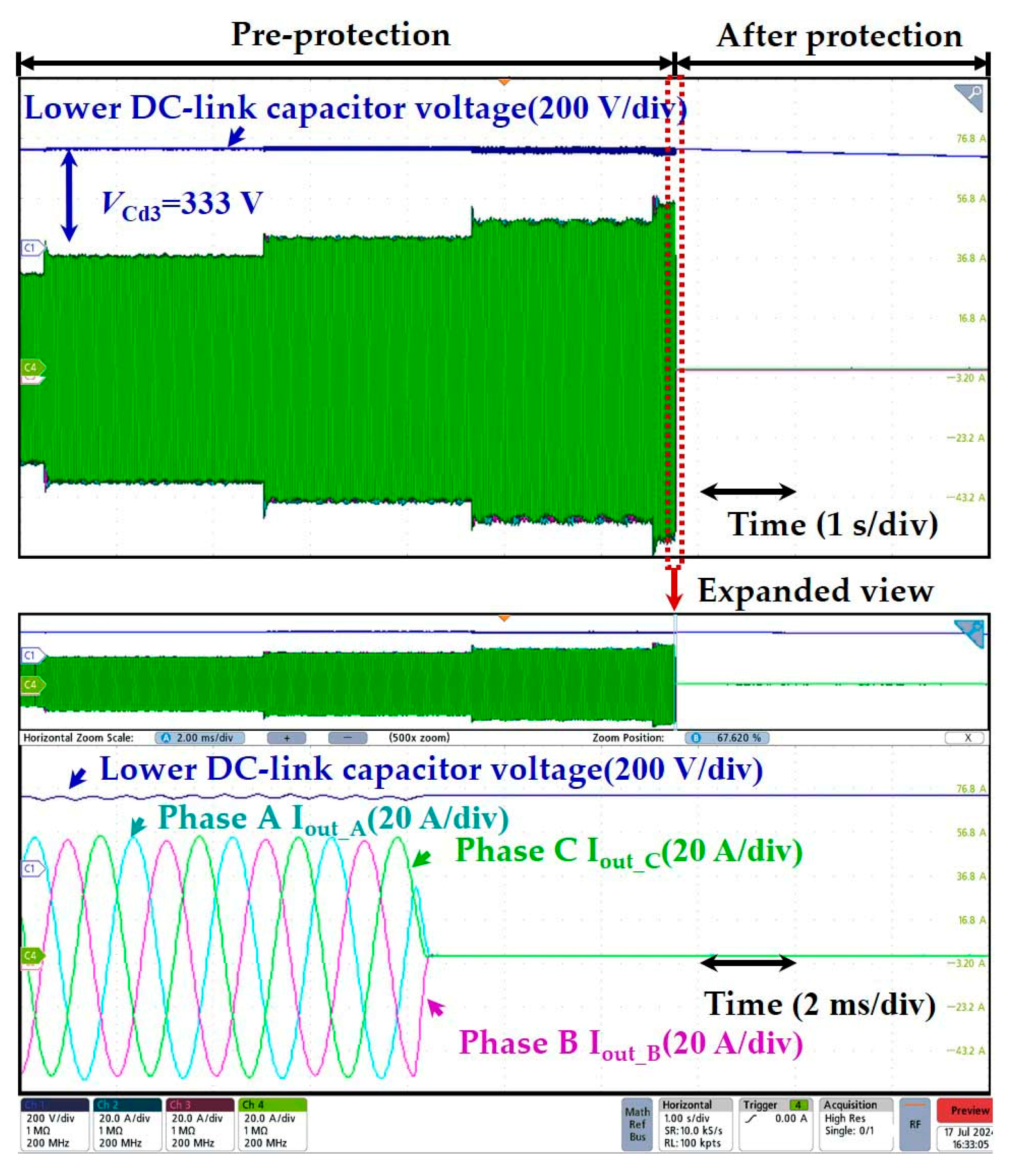
The software protection function was verified on this experimental platform. Since short-circuiting the converter directly to simulate faults is too dangerous, in this paper, the operating state of the system under extreme working conditions was simulated by changing the software protection threshold.
Figure 12 shows the waveform diagram of the overcurrent fault condition of the system under 1 kV high voltage. The software protection threshold is designed to be 60 A in this working state. The output current is increased by raising the modulation ratio to achieve the protection value. Experimental results show that when the output current reaches the protection threshold, the system promptly shuts off the control signal of the power device and disconnects the power supply via the emergency stop switch. The residual charge in the capacitor is discharged through bleed resistors, thereby achieving reliable software-level protection of the system under overcurrent conditions.
Finally, the system’s multi-level protection functionality under extreme operating conditions was verified. The waveform of Phase A drive signal under such conditions is shown in
Figure 13. Since performing a direct short-circuit test would be too dangerous, this study simulates extreme conditions by applying a signal with a reference voltage higher than the protection threshold to forcibly trigger a fault signal. Experimental results indicate that once the hardware fault signal is detected, the software receives the signal and quickly turns off the driving signals of other devices, and the protection time within 10 μs. Therefore, the multilevel protection function proposed in this paper can effectively protect the safety of the converter under extreme working conditions and ensure the stable and reliable operation of the converter. This paper presents the design of fault handling and multi-level protection mechanisms for SiC-based medium-voltage converters. By comparing with existing related studies in
Table 4, it is found that this work comprehensively considers both power device and system-level protection, integrating hardware and software protection measures. An adjustable protection threshold is implemented, making the proposed approach a valuable reference for the design and protection of converter systems based on SiC devices.
5. Conclusions
This paper proposes a multilevel fault monitoring and protection method applicable to medium voltage all-SiC-based hybrid multilevel converters. The common fault types of multilevel converters and monitoring characteristic values of each fault are analyzed, A multi-level fault detection, alarm, and protection method combining hardware and software is proposed. Experimental results demonstrate that the designed hardware short-circuit protection circuit can rapidly respond to overcurrent faults and shut down the device. On the software side, it is capable of detecting over-limit conditions in current, voltage, or temperature and triggering alarms and protection mechanisms. When fault values exceed critical thresholds, the system can also be swiftly shut down to ensure the safety of the converter. Meanwhile, under extreme operating conditions, the proposed multi-level protection method can also respond rapidly. Once hardware protection is triggered, it promptly shuts off the drive signals of other devices and disconnects the power supply, ensuring the safe and reliable operation of the converter.
Author Contributions
Validation, R.Z.; Formal analysis, Z.W. and H.T.; Writing—original draft, Z.C.; Writing—review & editing, K.X.; Supervision, Q.C.; Project administration, J.P. All authors have read and agreed to the published version of the manuscript.
Funding
This work is sponsored by the Science and Technology Program of China Southern Power Grid Co., Ltd. (H20241983).
Data Availability Statement
The original contributions presented in the study are included in the article.
Conflicts of Interest
Authors Kai Xiao, Qian Chen, Runming Zheng and Zhen Wang were employed by CSG EHV Electric Power, Research Institute, China Southern Power Grid Company Limited. The remaining authors declare that the research was conducted in the absence of any commercial or financial relationships that could be construed as a potential conflict of interest. The authors declare that this study received funding from the Science and Technology Program of China Southern Power Grid Co., Ltd. The funder had the following involvement with the study: Validation, Formal analysis, Writing—review & editing, Supervision.
Appendix A
Figure A1.
Characteristic of Id = f(Vds) for BSM250D17P2E004.
Figure A1.
Characteristic of Id = f(Vds) for BSM250D17P2E004.
References
- Li, Y.; Zhang, Y.L.; Yuan, X.B.; Zhang, L.; Song, Z.H.; Wu, M. 500 kW Forced Air-Cooled Silicon Carbide (SiC) Three-Phase DC/AC Converter with a Power Density of 1.246 MW/m3 and Efficiency >98.5%. IEEE Trans. Ind. Appl. 2021, 57, 5013–5027. [Google Scholar] [CrossRef]
- Yuan, X.B.; Laird, L.; Walder, S. Opportunities, challenges and potential solutions in the application of fast-switching silicon carbide (SiC) power devices and converters. IEEE Trans. Power Electr. 2021, 36, 3925–3945. [Google Scholar] [CrossRef]
- Zhang, L.; Yuan, X.B.; Wu, X.J.; Shi, C.C.; Zhang, J.H.; Zhang, Y.L. Performance evaluation of high-power SiC MOSFET modules in comparison to Si IGBT modules. IEEE Trans. Power Electr. 2019, 34, 1181–1196. [Google Scholar] [CrossRef]
- Wang, K.; Xu, L.; Zheng, Z.D.; Li, Y.D. Voltage Balancing Control of a Four-Level Hybrid-Clamped Converter Based on Zero-Sequence Voltage Injection Using Phase-Shifted PWM. IEEE Trans. Power Electr. 2016, 31, 5389–5399. [Google Scholar] [CrossRef]
- Colmenares, J.; Peftistsis, D.; Rabkowski, J.; Sadik, D.P.; Tolstoy, G.; Nee, H.P. High-efficiency 312-kVA three-phase inverter using parallel connection of silicon carbide MOSFET power modules. IEEE Trans. Ind. Appl. 2015, 51, 4664–4676. [Google Scholar] [CrossRef]
- Pan, J.Y.; Ke, Z.W.; Sabbagh, M.A.; Li, H.; Potty, K.A.; Perdikakis, W. 7-kV 1-MVA sic-based modular multilevel converter prototype for medium-voltage electric machine drives. IEEE Trans. Power Electr. 2020, 35, 10137–10149. [Google Scholar] [CrossRef]
- Ji, S.Q.; Palmer, J.; Huang, X.X.; Li, D.R.; Giewont, B. Impact of submodule voltage sensor noise in 10 kV SiC MOSFET modular multilevel converters (MMCs) under high dv/dt environment. In Proceedings of the 2020 IEEE Applied Power Electronics Conference and Exposition (APEC), New Orleans, LA, USA, 15–19 March 2020. [Google Scholar]
- Peftistsis, D.; Tolstoy, G.; Antonopoulos, A.; Rabkowski, J.; Lim, J.K.; Bakowski, M. High-Power Modular Multilevel Converters With SiC JFETs. IEEE Trans. Power Electr. 2012, 27, 28–36. [Google Scholar] [CrossRef]
- Yang, Y.; Pan, J.Y.; Wen, H.Q.; Na, R.S.; Wang, H.Y.; Zhang, Z.W. An Optimized Model Predictive Control for Three-Phase Four-Level Hybrid-Clamped Converters. IEEE Trans. Power Electr. 2020, 35, 6470–6481. [Google Scholar] [CrossRef]
- Zhao, Y.H.; Pan, J.Y.; Yan, S.; Luo, Y.; Tang, H.B.; Li, J. Novel Voltage-Balance Control of Four-Level Hybrid-Clamped Converter With Open-Loop Optimized Common-Mode Voltage Injection. IEEE Trans. Power Electr. 2022, 37, 14045–14051. [Google Scholar] [CrossRef]
- Montanari, G.C.; Hebner, R.; Morshuis, P.; Seri, P. An approach to insulation condition monitoring and life assessment in emerging electrical environments. IEEE Trans. Power Deliv. 2019, 34, 1357–1364. [Google Scholar] [CrossRef]
- Feng, X.Y.; Xiong, Q.; Gattozzi, A.; Montanari, G.C.; Seri, P.; Hebner, R. Cable commissioning and diagnostic tests: The effect of voltage supply frequency on partial discharge behavior. In Proceedings of the 2018 12th International Conference on the Properties and Applications of Dielectric Materials (ICPADM), Xi’an, China, 20–24 May 2018. [Google Scholar]
- Ghat, M.B.; Shukla, A. Series-Stacked Hybrid Modular Converter with DC Fault Blocking Capability for HVDC Application. In Proceedings of the 2018 IEEE Energy Conversion Congress and Exposition (ECCE), Portland, OR, USA, 23–27 September 2018. [Google Scholar]
- Li, M.; Chen, K.; He, J.H.; Luo, Y.P.; Wang, X.J.; Luo, G.M. Analysis of Fault Characteristics of Hybrid Multiterminal HVDC Transmission System. In Proceedings of the 2020 2nd International Conference on Smart Power & Internet Energy Systems (SPIES), Bangkok, Thailand, 15–18 September 2020. [Google Scholar]
- Ke, L.Z.; Liu, Z.X.; Zhang, Y. Fault Diagnosis of Modular Multilevel Converter Based on Optimized Support Vector Machine. In Proceedings of the Chinese Control Conference, Shenyang, China, 27–29 July 2020. [Google Scholar]
- Li, B.B.; Shi, S.L.; Wang, B.; Wang, G.L.; Wang, W.; Xu, D.G. Fault Diagnosis and Tolerant Control of Single IGBT Open-Circuit Failure in Modular Multilevel Converters. IEEE Trans. Power Electr. 2016, 31, 3165–3176. [Google Scholar] [CrossRef]
- Xiao, S.J.; Lan, S.; Yuan, Y.B.; Chen, M.J.; Jin, T. A Line Fault Type Detection Method Based on Optimal Sample Training Support Vector Machine in MMC-HVDC Transmission System. In Proceedings of the 2019 IEEE 8th International Conference on Advanced Power System Automation and Protection (APAP), Xi’an, China, 21–24 October 2019. [Google Scholar]
- Han, K.L.; Cai, Z.X.; Liu, Y. Study on protective performance of HVDC transmission line protection with different types of line fault. In Proceedings of the 2011 4th International Conference on Electric Utility Deregulation and Restructuring and Power Technologies (DRPT), Weihai, China, 6–9 July 2011. [Google Scholar]
- Liu, X.X.; Judge, P.; Chaffey, G.; Leterme, W.; Hertem, V.D. Impact of Current Limiter Implementation in MMC Control on AC Fault-Ride-Through and System Distance Protection. In Proceedings of the 2024 Energy Conversion Congress & Expo Europe (ECCE Europe), Darmstadt, Germany, 2–6 September 2024. [Google Scholar]
- Liu, S.Y.; Wang, Q.; Zhang, L.; Zheng, S.S. The Digital System Architecture for Multi-Level Collaborative Monitoring and Analysis of Converter Station Main Equipment. In Proceedings of the 2024 4th International Conference on Smart Grid and Energy Internet (SGEI), Shenyang, China, 13–15 December 2024. [Google Scholar]
- Zhang, D.W.; Lu, H.; Xu, C.C.; Hu, X.X.; Han, R.H.; Cao, Y.S. Automated Fault Diagnosis Technology for Modular Multilevel Converter Based on Infrared Temperature Measurement. In Proceedings of the 2024 IEEE 7th Eurasian Conference on Educational Innovation (ECEI), Bangkok, Thailand, 26–28 January 2024. [Google Scholar]
| Disclaimer/Publisher’s Note: The statements, opinions and data contained in all publications are solely those of the individual author(s) and contributor(s) and not of MDPI and/or the editor(s). MDPI and/or the editor(s) disclaim responsibility for any injury to people or property resulting from any ideas, methods, instructions or products referred to in the content. |
© 2025 by the authors. Licensee MDPI, Basel, Switzerland. This article is an open access article distributed under the terms and conditions of the Creative Commons Attribution (CC BY) license (https://creativecommons.org/licenses/by/4.0/).
