Review

Advancements and Challenges in Floating Photovoltaic Installations Focusing on Technologies, Opportunities, and Future Directions

by
Ryan Bugeja
1,*,
Luciano Mule' Stagno
1,
Cyprien Godin
1,
Wenping Luo
2 and
Xiantao Zhang
2
1
Institute for Sustainable Energy, University of Malta, MXK1531 Msida, Malta
2
State Key Laboratory of Ocean Engineering, Shanghai Jiao Tong University, Shanghai 200240, China
*
Author to whom correspondence should be addressed.
Energies 2025, 18(22), 5908; https://doi.org/10.3390/en18225908
Submission received: 8 October 2025 / Revised: 27 October 2025 / Accepted: 1 November 2025 / Published: 10 November 2025

Abstract

Floating and offshore photovoltaic (FPV) installations present a promising solution for addressing land-use conflicts while enhancing renewable energy production. With an estimated global offshore PV potential of 4000 GW, FPV systems offer unique advantages, such as increased efficiency due to water cooling effects and synergy with other offshore technologies. However, challenges related to installation costs, durability, environmental impacts, and regulatory gaps remain. This review provides a comprehensive and critical analysis of FPV advancements, focusing on inland, nearshore, and offshore applications. A systematic evaluation of recent studies is conducted to assess technological innovations, including material improvements, mooring strategies, and integration with hybrid energy systems. Furthermore, the economic feasibility of FPVs is analysed, highlighting cost–benefit trade-offs, financing strategies, and policy frameworks necessary for large-scale deployment. Environmental concerns, such as biofouling, wave-induced stress, and impacts on aquatic ecosystems, are also examined. The findings indicate that while FPV technology has demonstrated significant potential in enhancing solar energy yield and water conservation, its scalability is hindered by high capital costs and the absence of standardised regulations. Future research should focus on developing robust offshore floating photovoltaic (OFPV) designs, optimising material durability, and establishing regulatory guidelines to facilitate widespread adoption. By addressing these challenges, FPVs can play a critical role in achieving global climate goals and accelerating the transition to sustainable energy systems.

1. Introduction

The increasing demand for renewable energy has accelerated research into novel solutions that maximise generation while minimising the environmental impact. Floating photovoltaic (FPV) systems have emerged as a promising alternative to ground-mounted photovoltaic (GPV) farms, particularly in regions where land scarcity, urban expansion, and agricultural demands limit terrestrial solar installations [1,2]. FPVs can utilise artificial reservoirs, lakes, and even offshore environments, offering additional benefits such as natural cooling effects and reduced water evaporation [3,4,5,6,7,8,9]. These systems can also be integrated with other renewable energy systems such as offshore wind or hydroelectric plants [6,10].
Despite these advantages, the deployment of FPV systems—particularly in offshore and nearshore environments—remains limited due to several technical, economic, and regulatory challenges. OFPVs are subject to higher wave loads, extreme weather conditions, and biofouling, which impact their structural durability and long-term energy yield [11]. Furthermore, FPV installations currently lack international regulatory frameworks and standardised design criteria, leading to uncertainty in project development and financing. While existing reviews have focused on inland floating photovoltaic (LFPV) applications, comprehensive analyses of offshore floating photovoltaic (OFPV) feasibility, technological advancements, and economic barriers are still lacking.
This review systematically examines the technological advancements, environmental impact, and economic viability of FPV systems, with a particular focus on offshore applications. This review differs from the existing literature by focusing on select technological advancements and gaps, rather than providing a historical overview of floating PV installations. The authors believe these factors will shape the future success of floating PV systems, particularly in offshore environments. By analysing data from several peer-reviewed studies, case reports, and real-world deployments, this study addresses the following key questions:
  • What are the latest technological innovations in FPV mooring systems, materials, and hybrid renewable energy integration?
  • What are the major cost and durability challenges facing OFPV adoption, and how can they be mitigated?
  • What environmental impacts do FPV systems have on aquatic ecosystems, and what regulatory frameworks are needed for sustainable deployment?
The findings of this review aim to provide a roadmap for scaling FPV technology while addressing the remaining scientific, economic, and policy challenges that hinder its large-scale deployment.

Review Methodology

This paper constitutes a scoping review of floating photovoltaic systems, synthesising technological, environmental, and techno-economic findings to identify current research gaps and future development priorities. This review follows a structured scoping review approach based on the PRISMA-ScR [12] guidelines for transparency and reproducibility. The literature was collected using search terms such as “floating photovoltaics,” “offshore solar,” “marine solar,” and “FPV”. Recognising that commercial advancements and market trends are often detailed in industry reports, the search strategy was designed to include grey literature in addition to peer-reviewed academic publications. This approach was essential to fulfil the review’s objective of comprehensively mapping the FPV market. The inclusion criteria for the literature required the following:
-
Quantitative performance or techno-economic data.
-
Discussion of offshore FPV design, materials, or environmental interaction.
-
Practical designs beyond numerical models with either a high technology readiness level (TRL) or a forward vision to advance the current TRL.
Moreover, this review grounds its ecological and life cycle discussions by synthesising findings from a variety of empirical monitoring and modelling studies. These sources are complemented by comprehensive Life Cycle Assessment (LCA) data to evaluate the total environmental burden associated with material selection, mounting, and system operation.

2. Benefits and Potential Implementation of FPVs

2.1. Benefits of FPVs

Floating photovoltaic (FPV) systems provide multiple benefits compared to conventional GPV installations, particularly in regions where land scarcity or competing land-use priorities pose challenges [1,2,13]. By utilising water bodies such as reservoirs, canals, and offshore environments, FPVs reduce land occupation while also enhancing energy efficiency, water conservation, and hybrid renewable energy integration.
Furthermore, thanks to their rapid assembly and installation and less disruptive dismantling, LFPV platforms can be simpler and less expensive to install than GPV farms. Their accessibility on the surface of the water can make maintenance operations easier [14]. Another important advantage of LFPVs is that they reduce water evaporation [3,15]. According to research conducted in Australia, up to 40% of the water in open tanks is lost through evaporation [13]. By covering just 30% of the water surface with photovoltaic panels, evaporation can be reduced by up to 49%, preserving crucial freshwater resources, particularly in agricultural areas [7,8]. A study by Tian et al. [16] found that annual water reservoir evaporation losses equate to nearly 73% of the 2010 municipal water withdrawal. According to Nisar et al. [3], LFPV systems can reduce water evaporation by 17% when the water body is partially covered and by 28% when the water body is fully covered. Moreover, Elminshawy et al. [9] found that floating PVs installed with a 10° tilt can reduce water evaporation by 83.33%. Also, the shading effect of LFPVs prevents the growth of algae in the water beneath the panels, which is beneficial for maintaining water quality and protecting aquatic ecosystems. Reducing the growth of algae is of vital importance for the preservation of fish species and other marine life [17].
Solar panels installed on water also tend to increase energy production thanks to the natural cooling effect of the water, which prevents the panels from overheating and improves their efficiency [3,4]. A study conducted on “the offshore oil platform QMS Al Bahia in Abu Dhabi” evaluated the performance of an OFPV system under the climatic conditions of the Persian Gulf. The research highlighted that the offshore environment positively impacts the efficiency of PV panels, with a maximum temperature difference of 4.1 °C observed in November compared to ambient conditions. This temperature reduction contributes to enhanced energy yields [18].
In their study conducted in West Java Province in Indonesia, Sukarso et al. [5] found that the temperature difference between water-based and ground-based zones can be up to 3.8 °C in November and December and 15 °C in early October. Furthermore, the cooling effect lowers the front PV temperature by 2 to 4% and the back PV temperature by 5 to 11% compared to similar ground-based PV modules (GPVs) [3]. This phenomenon results in a higher energy conversion efficiency of the FPV modules which can generate up to 10% more electricity [6].
By generating renewable energy, FPVs help to reduce greenhouse gas emissions, reduce dependence on fossil fuels, provide energy independence, and align with the EU’s goal to reach climate neutrality by 2050 [19,20]. Another opportunity is hybridisation of FPVs with hydroelectric power stations. This approach uses the infrastructure of hydroelectric dams, combining solar and hydroelectric power to create a more reliable and constant energy source while maximising the use of renewable resources [10,21].
The economic benefits and profitability of FPVs are compelling. FPVs are economically attractive because of reduced land costs, increased energy production, and lower maintenance costs (for LFPVs) [22]. In addition, some floating platforms, made of high-density polyethylene resistant to UV rays and corrosion, can be recycled, improving their durability and profitability.

2.2. Potential Implementation of FPVs

In their study, Silalahi et al. [23] analysed 40 years of wave height data and maximum wind speeds to identify potential locations to implement OFPV installations. The Gulf of Guinea and the Indonesian archipelago were identified as the most favourable sites for OFPV installations. Their work showed a “huge potential” for OFPV systems in calm tropical regions, possibly generating up to 1 million TWh per year in areas with winds rarely stronger than 15 m/s and waves rarely larger than 6 m. According to the International Energy Agency [24], in 2022, the global electricity consumption was approximately 25,000 TWh, with PVs generating only 6.2% of this demand. This means that the potential from OFPVs in tropical regions represents around forty times the current global electricity production.
Figure 1 represents the “Flowchart of site assessments of OFPV sites” used by Silalahi et al. [23]. This flowchart illustrates how potential OFPV installation sites are identified by excluding areas with 40 years of historical storm paths, protected areas, and Economic Exclusive Zones (two hundred miles) and after eliminating areas where wave heights and wind speeds are too high. After suitable maritime areas were assessed for the installation of OFPV systems, Silalahi et al. [23] concluded that most of the potential areas experience winds stronger than 20 m/s and waves larger than 10 m. With these conditions, OFPVs may not be economically feasible compared to GPVs or LFPVs. However, the study concluded that some regions within 5–12 degrees of latitude of the Equator, such as the Gulf of Guinea, the Indonesian archipelago, the Greek Isles, and the northern Adriatic Sea, are the most adequate to implement OFPV installations [23].

3. Floating and Offshore PV Technology

3.1. Concept and Design of Floating, Nearshore, and Offshore PV Systems

A floating photovoltaic installation is an emerging concept that combines conventional PV technology with floating systems. For the purpose of this review, this technology will be divided in two categories:
  • Inland floating PVs (LFPVs) are characterised by the implementation of systems over water bodies such as lakes, lagoons, irrigation and agricultural ponds, canals, dams, fish farms, wineries, and wastewater treatment plants.
  • Offshore PVs are located, at a certain distance, off the coast, in deep or shallow waters [26]. These installations can either be floating (OFPVs) or installed on a fixed structure attached to the seabed (OPVs).
Certain aspects need to be initially considered to develop a stable structure that is both economically feasible and non-intrusive to the surrounding environment. This involves both the construction process, as well as the surroundings since the climate and weather conditions directly influence the system’s performance. Similar to GPV installations, one must set a suitable tilt angle and orientation and choose the distance between individual panels to prevent shading and facilitate their maintenance [1].
The most significant criteria that should be borne in mind while selecting a suitable space for a floating PV facility include the following:
  • Environmental factors such as solar radiation, shading, or fog that would directly influence electricity generation.
  • Elements that might disturb installation and maintenance, namely the depth of water and regions prone to freezing or interference by dam facilities.
  • Connection with power systems, such as the distance to load and distribution lines.
  • Legal restrictions to ensure that a given aquatic area is not protected, does not require special countermeasures, and is not designated for marine traffic.

3.2. Components of a Floating PV System

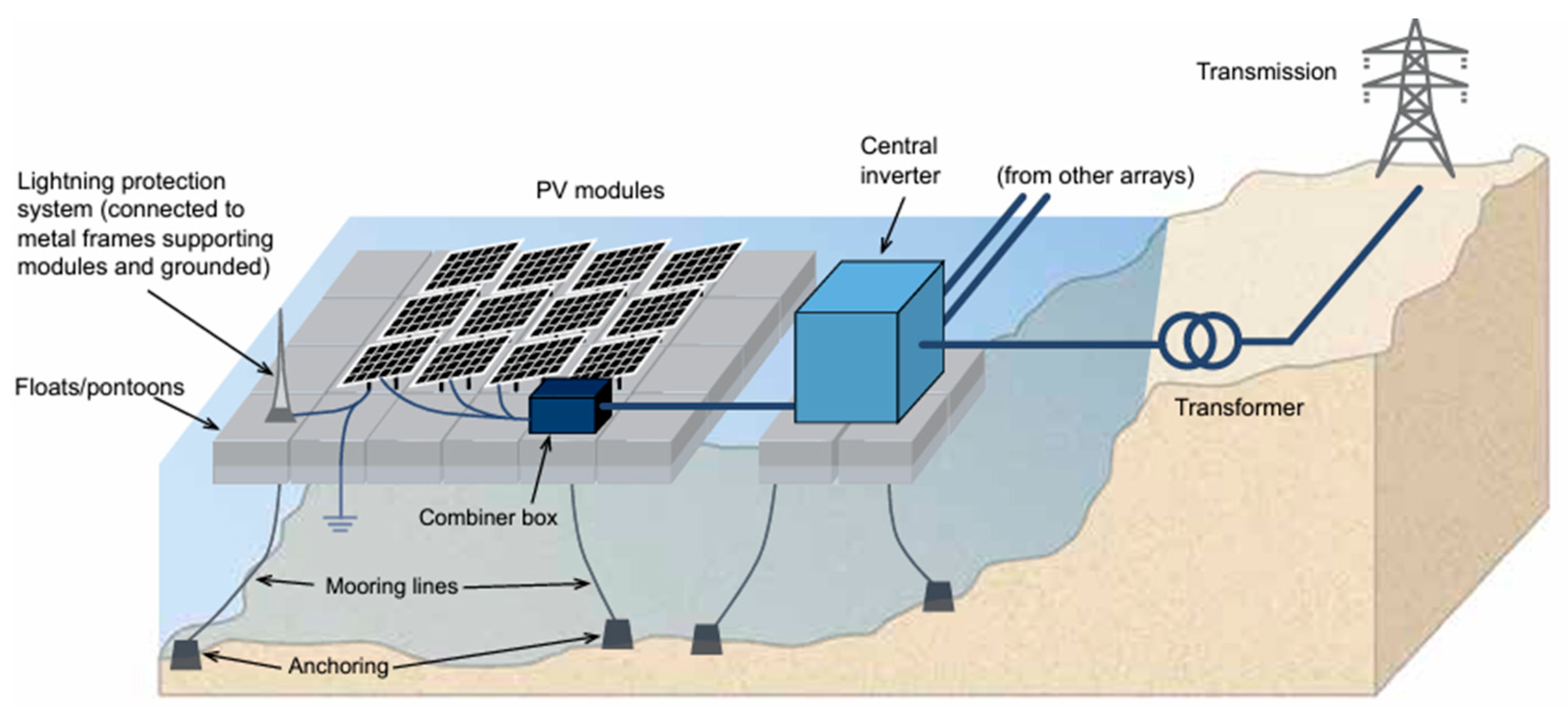
Apart from traditional components of a GPV installation, a floating PV system includes several additional elements characterised in Table 1 [1]. The layout of a typical floating PV system is depicted in Figure 2 [27].

3.3. Floating PV Designs for Water Bodies

Various research groups worldwide are proposing their designs for floating devices to support photovoltaic panels. The “Hydrelio® aiR Optim” LFPV design, which is widely implemented by the French company “Ciel et Terre” [28], is designed for agitated bodies of water such as dam reservoirs or basins. To date, 825 MWp floating PVs have been installed using this design. The floater is composed of high-density polyethylene (HDPE) and can support modules of up to 670 W in size. According to the company, the design is wave-resistant, snow-compatible, and typhoon-proof, compatible with high water level variation and dry ponds. The anchoring design can be adapted according to site requirements [28].
Another floating PV structure manufactured by the Japanese company “Sumitomo Mitsui Construction Co., Ltd.” is made of high-density polyethylene (HDPE) material and uses UV-absorbing agents to ensure protection against UV light. The float’s overall weight is 11.9 kg, whereas the bridges weigh no more than 2.2 kg. The inclination angle of the solar panels fixed on the top of the structure is set at 10° [1]. Structural elements include buoyant floats, upright stands, bridges, binding bands, anchor bolts, and solar panel brackets [29]. When utilising lightweight floaters, one must focus more on durable mooring to avoid floats overtopping due to unexpected weather conditions. These incidents are not something new, as described in Section 5.2.

3.4. Nearshore PV System Designs

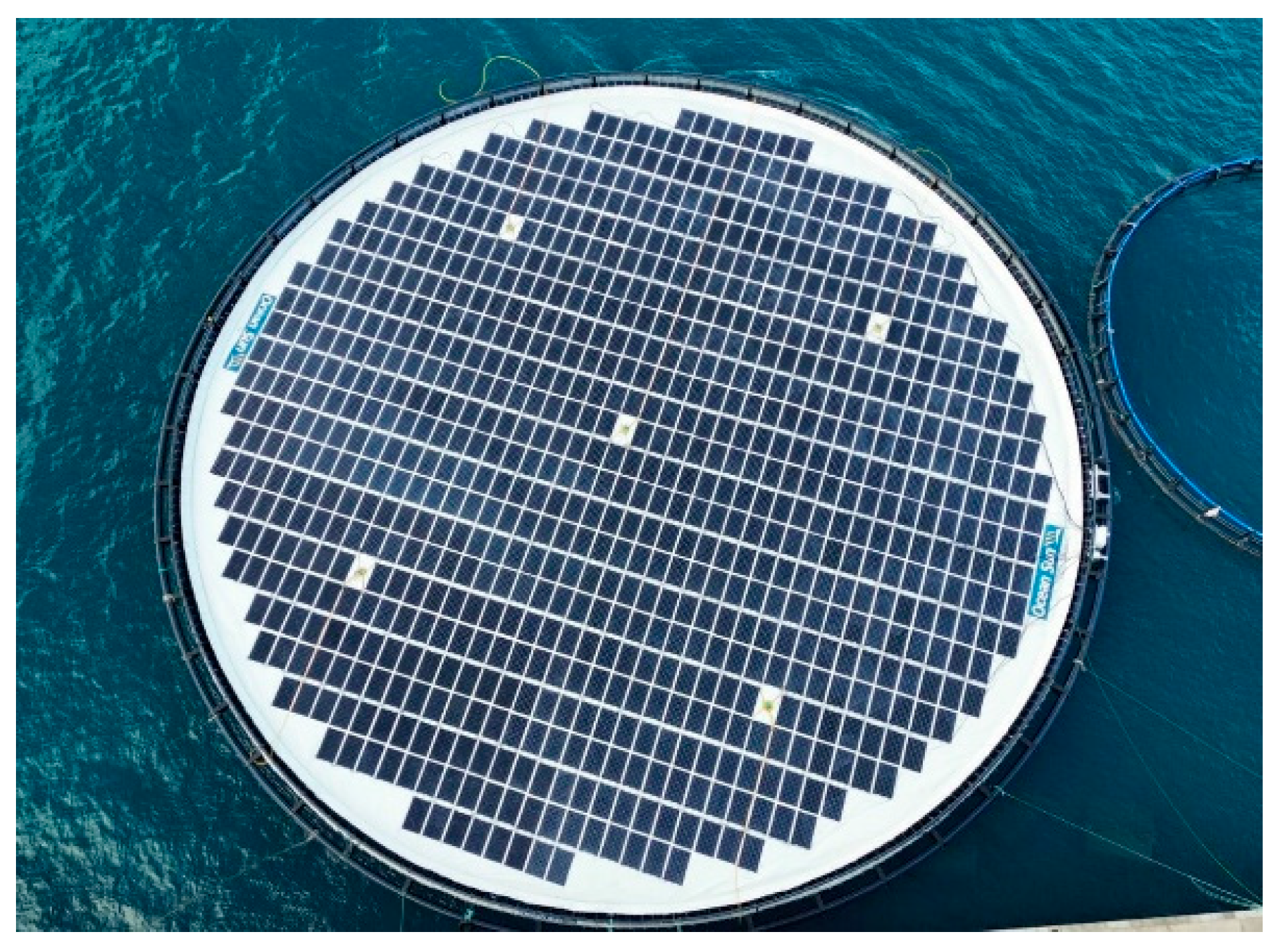
In December 2023, the Norwegian company Ocean Sun and its partners completed the installation of one of their nearshore solar PV systems near La Palma in Spain [30], shown in Figure 3.
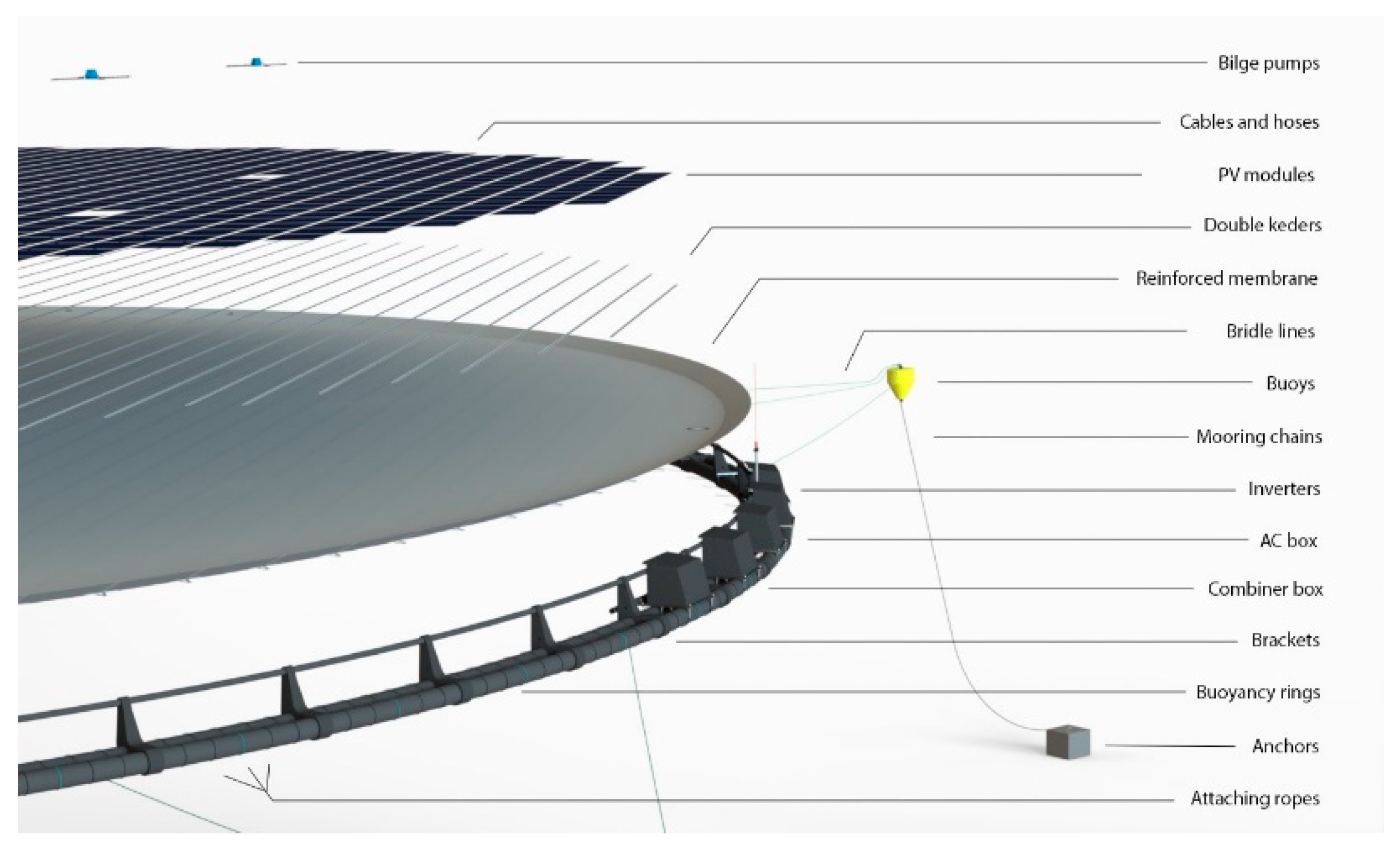
The project named “BOOST” has a theoretical power of 275 kWp and it is part of an EU Horizon project. This project implemented Ocean Sun’s patented FPV technology, illustrated in Figure 4 [30,31].
The circle-shaped design includes a reinforced membrane that lies directly on the water surface. According to Ocean Sun, the PV modules are installed horizontally for the optimal cooling effect. The membrane is anchored to the seabed using buoys and mooring chains [31]. In their study, Kjeldstad et al. [32] analysed the performance of this patented FPV technology and quantified the cooling effect due to the water body underneath. The result of this study showed that FPV systems with a membrane resting on the water body have a 5 to 7% higher yield than systems cooled by air from May to July. They concluded that this yield difference relies on the changes in temperatures of air and water [32]. According to the Ocean Sun company, the technology’s installation is simple, safe, and quick. Furthermore, it has proved to be robust in high wind, waves, and strong currents [31]. The downside to this design is that small wave heights can overtop and fill the membrane with water. If the drainage pump fails, this could lead to rupturing of the membrane. Furthermore, there is a concern regarding the power consumption and maintenance of the drainage pump.

3.5. Offshore PV System Designs

The potential benefits of OFPV systems are accentuated in islands and small states with limited land area and extensive territorial waters. For example, the Maltese islands cover an area of around 316 km2 of land with around 3000 km2 of territorial waters. In total, 33% of the islands are covered by buildings, and most of the remaining land is not available for PV installations due to legislation that prevents installations on arable or environmentally sensitive land [33]. Solar energy production is not yet exploited in this considerable aquatic space. The relevance of OFPV systems to this region is also highlighted by Malta’s high annual solar insolation [34]. In 2015, Maltese researchers launched one of the first OFPV prototypes, as part of the Solaqua project. Mule’ Stagno et al. [4,35] built and tested prototypes of OFPV systems using different PV module technologies, mounting techniques, and floating devices. The installations were exposed to considerable waves and wind but not in very deep sea to limit the cost of mooring and anchoring and avoid interference with marine activities. In this study, four prototypes were evaluated:
  • Reinforced expanded polystyrene (EPS) with thin-film PV modules.
  • Crystalline PV module float.
  • Steel pipe raft with HDP drums.
  • Self-floating spherical shapes with PV modules built into them.
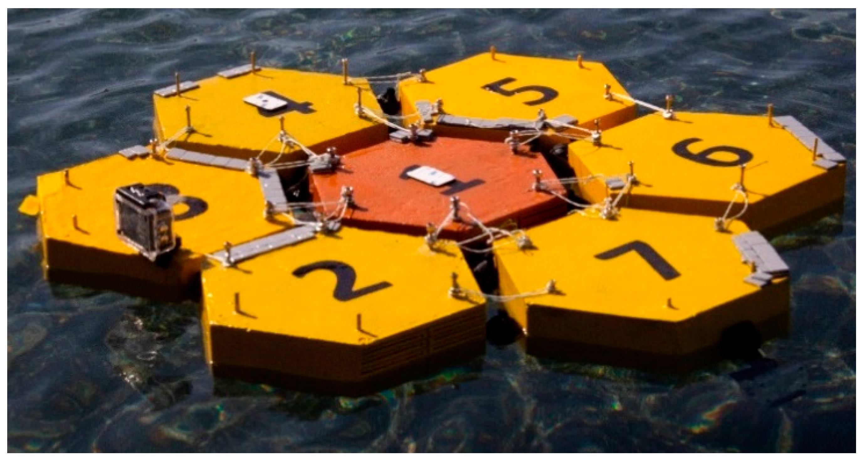
The lessons learnt in terms of feasibility and costs from this pioneering OFPV study have been of crucial importance for the development of OFPV installations. In 2021, the Maltese researchers patented their new design for OFPVs involving modular hexagonal rafts [36]. Hydrodynamic simulations of the designs were performed, and small-scale prototypes were tested in wave tanks, as shown in Figure 5 [36]. The hexagonal shape allows a wave response motion with high degrees of freedom, preventing excessive overtopping in high-wave conditions. Furthermore, the modularity of the design enables unlimited scaling and facilitates production and transport.
López et al. [37] developed a new OFPV concept termed the “HelioSea”. The design of this innovative concept uses the tension-leg platform (TLP) technology, already used for offshore oil and gas installations and offshore wind turbines. The HelioSea concept uses steel wire ropes and a mast for the legs and tubular steel members as pontoons. However, the authors of the concept explain that other materials, such as fibre-reinforced polymers, may be explored for future deployment. The main components of this design include stainless steel wire ropes for taut mooring, pontoons, a mast to support dual-axis PV tracking, and the PV modules [37].
Compared to other offshore designs, the HelioSea concept could have the advantage of being mobile while having minimal vertical motion. Moreover, when compared to other floating solar designs, the HelioSea concept has panels installed at a sufficient height above sea level, possibly avoiding overtopping in extreme wave conditions. However, the main disadvantages of this system could be the high capital, difficult maintenance, and the fatigue of tension. A dual-axis tracking system requires moving parts such as gears and electric motors. These components can increase maintenance costs considerably in an offshore environment and increase the probability of failure.
Another full-scale prototype designed for harsh offshore conditions has recently been launched in Norway. The modular design named “XolarSurf” [38] was developed by Saipem’s subsidiary Moss Maritime, based in Norway. The XolarSurf system is composed of almost 500 individual floaters and has a total capacity of up to 13.5 MW. Each floater, shown in Figure 6 [39], is composed of eight pontoons, a flexible steel frame, a connector system, and a solid PV mounting structure and could have a capacity of up to 35–45 kWp. According to the company, this system can withstand waves up to 8 m in height, and the modular design allows easy relocation to new sites or expansion [38,39,40,41]. While this concept looks technically feasible, one must assess the economic viability of such a large structure when compared to the number of panels installed on top.
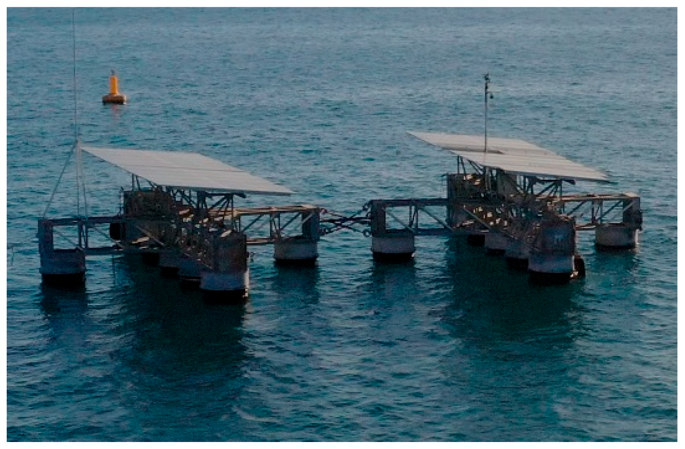
In 2023, SolarinBlue [42] launched the first OFPV farm in French territorial waters, specifically in the Port of Sète-Frontigan. The system, termed Sun’Sète (shown in Figure 7 [42]), is composed of two floating units generating a total of 20 KWp. Elevated truss technology was used, and the prototype could withstand waves up to 12 m and has a wind resistance of up to 200 km/h. The raft is made from aluminium and has a nominal lifetime of 30 years. Taut mooring lines with helical anchors were used. The company has recently secured a multimillion-euro grant aiming to deploy a 1 MWp OFPV farm in the same port. This project is being termed Mega Sète. The installation will have a floating power transformer unit, and energy will be transmitted to land through a submarine cable. Similar to XolarSurf, one must assess the economic feasibility of such large structures and the corrosion effect of the marine environment on the metal being used.
Another design by the company Oceans of Energy [43] has the PV modules installed on floating rafts very close to the sea surface. These systems have been tested in the North Sea and were reported to have withstood more than 13 m high waves. A floating solar farm, termed North Sea Three (NS3), has recently been completed by this company. This farm is projected to be expanded into a multi-megawatt system [44]. While this design can be very cost-effective and simple to implement, one must assess the effect of wave overtopping and possible effect of fouling growth due to the proximity of the PV modules to the sea surface.
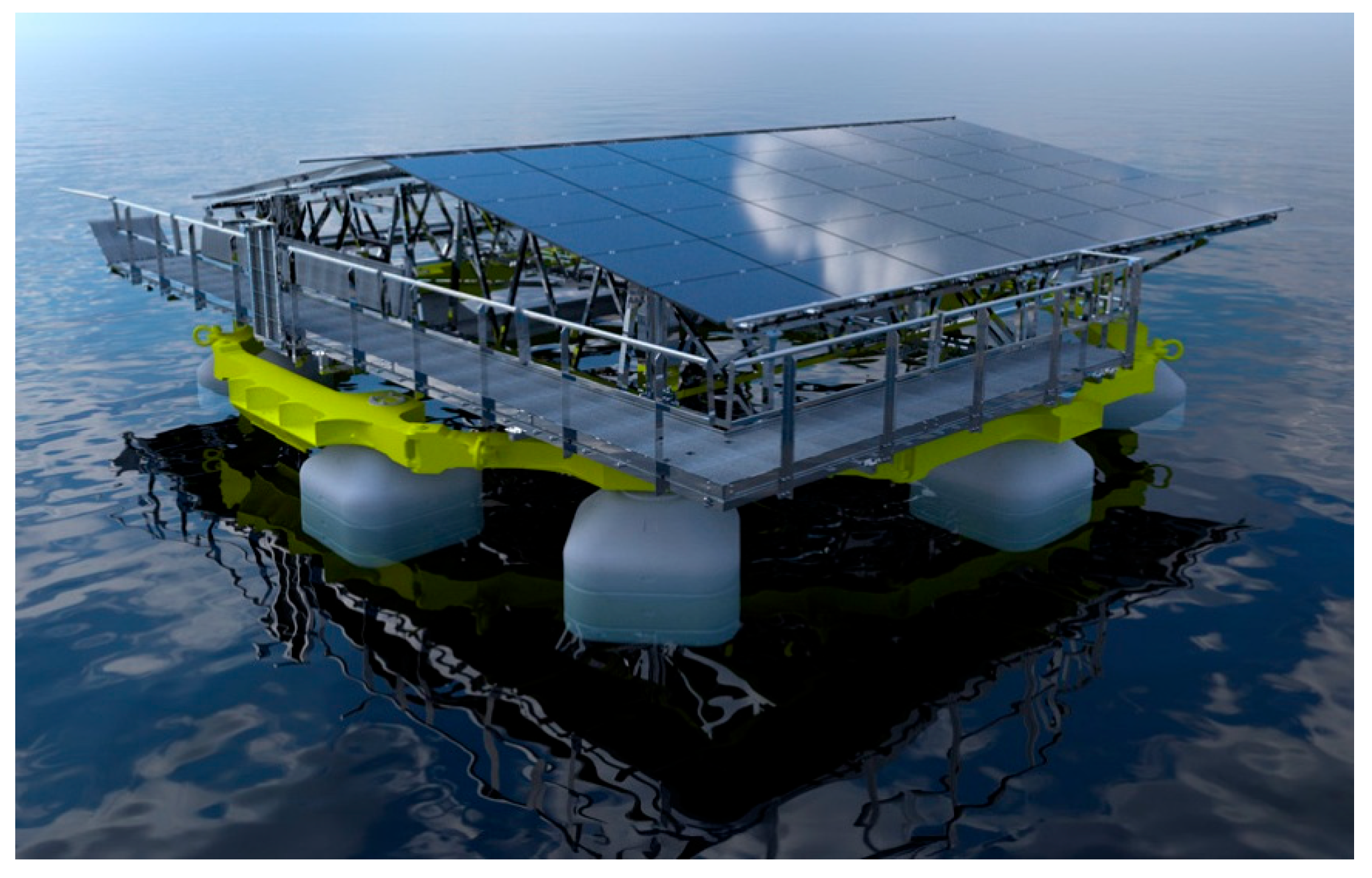
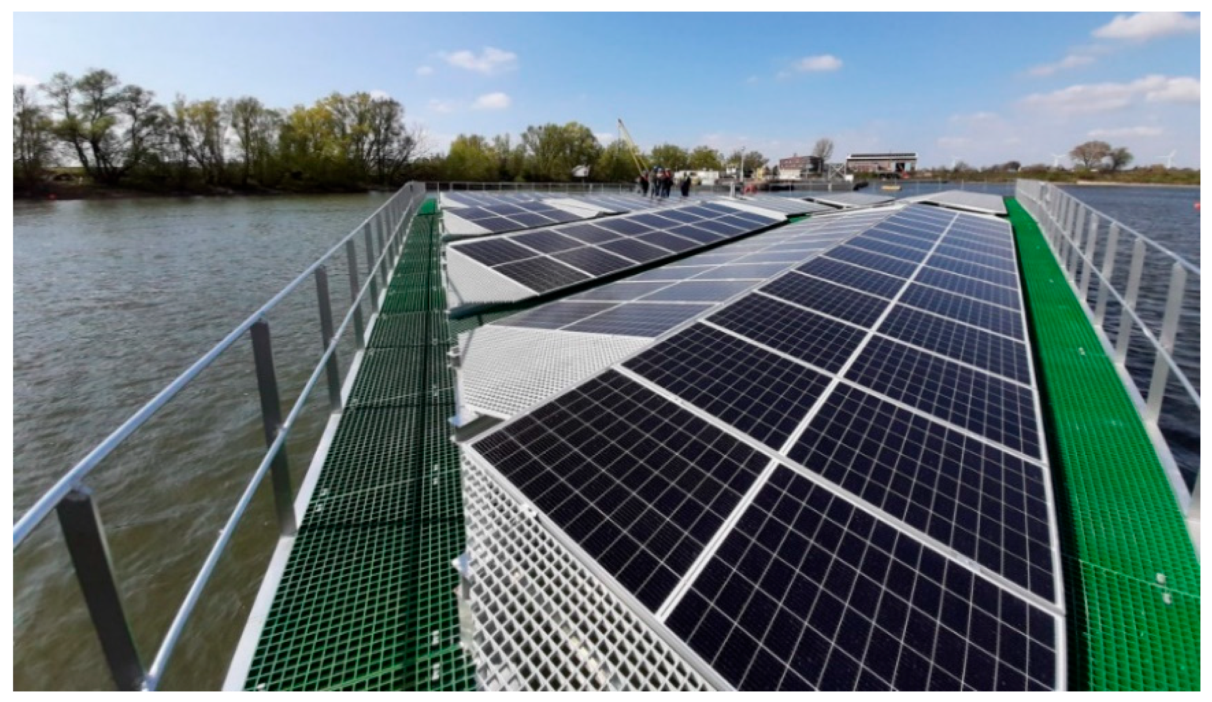
The company SolarDuck [45] developed a triangular-shaped platform floating on water, designed to withstand extreme conditions in the North Sea. The company states that the platform can withstand significant wave heights of more than 5 m and hurricane wind speeds of more than 30 m/s and has a lifetime of more than 30 years. The platform is elevated from the surface of the sea to avoid wave impacts and utilises offshore-grade aluminium. These platforms boast a low probability of PV cell micro-cracks due to the reduced water impact and limited electrical component corrosion due to the elevation from the sea surface. Finally, Figure 8 [45] shows that the platform also includes walkways with FRP grating and safety fences to allow for easy and safe maintenance at sea. The same company improved their design, creating Merganser, a 0.5 MWp OFPV installation, installed in the North Sea. This technology is somewhat similar to XolarSurf and SolarinBlue, and therefore, economic feasibility and corrosion also need to be assessed when it comes to large metallic structures.
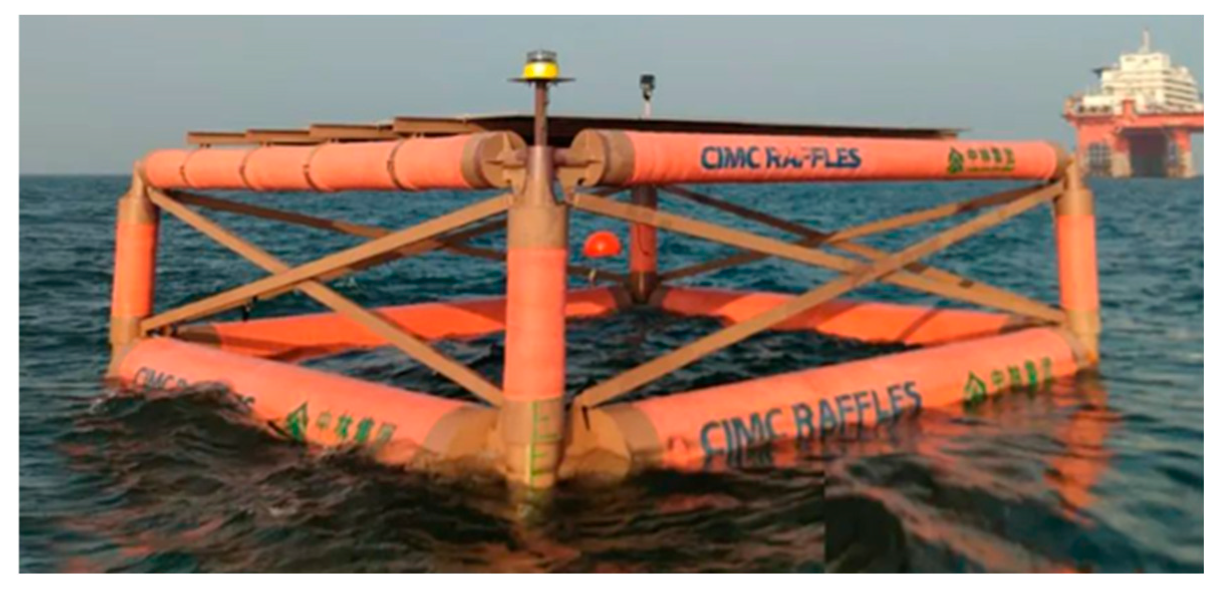
In October 2023, Yantai CIMC Raffles Offshore Technology Group and China Forestry Green Carbon (Beijing) Technology Co., Ltd., launched an OFPV platform made from a bamboo-based composite material, shown in Figure 9 [46]. This material is claimed to be lightweight, low-cost, resistant to seawater corrosion, and environmentally friendly [46]. The same company also launched China’s first semi-submersible OFPV platform in Yantai in April 2023. Four modules are connected for a total power capacity of 400 kW. It is designed to survive wave heights of 6.5 m, wind speeds of 34 m/s, and a tidal variation of 4.6 m [47].
Another OFPV was launched in August 2023 by SDEPCI (Shan Dong Electric Power Consulting Institute), with a total capacity of approximately 15 kW. The photovoltaic array is raised on an elevated truss design similar to SolarinBlue [48]. An OFPV system designed with a high freeboard was launched in September 2024 in the Yellow Sea in the southern part of the Shandong Peninsula. This platform was designed to survive wave heights of up to 10 m, making it the highest wave-resistant OFPV platform in China. The platform involves a hexagonal truss structure with 64 plastic buoys installed at the bottom. The structure height above still water is 7.5 m, and the draught is 1.5 m. The hexagon side length is 25 m, and a total of 434 PV modules are installed. Six anchor chains are used to moor the structure at a water depth of 30 m. Each anchor chain weighs 55 tons and is about 300 m long [49]. Such a massive structure has a high chance of surviving extreme weather conditions. However, one must assess its economic viability when compared to other technologies. Table A1 consolidates a critical analysis and comparison of different OFPV technologies.

4. Technological Components, Innovations, and Challenges

4.1. Environmental Stresses

PV modules need to last several years to be economically viable. This means that their construction must be robust and resistant to various environmental conditions. A SERIS report analysed the impacts of environmental stresses on PV module degradation [50]. This study indicates that moisture and mechanical stresses have the highest impact on floating PV systems. Moreover, hot spots and shading have a moderate impact since water bodies usually have fewer shading objects such as buildings. Furthermore, the air is usually cleaner when compared to land which results in less dust depositing on the surface of PV modules [4]. Finally, high and low temperatures have a lower impact on floating PV systems. It is important to consider these potential environmental stresses when choosing and implementing floating PVs’ technological components.

4.2. Materials for Floating Structures

Due to its advantages, high-density polyethylene (HDPE) is the most frequently used material for LFPV systems. However, its extensive usage raises concerns about its potential effect on the environment and marine life. Ghanadi et al. [51] studied the impact of natural weathering on HDPE piles in coastal waters, with a nine-year exposition of the sample. The results confirmed that the sample undergoes oxidation due to exposure to mechanical stresses, biodegradation, and seawater. These factors may have a higher impact on the surface of HDPE than UV irradiation.
A study conducted by Choi et al. [52] analysed the use of diverse types of polyethylene for floating structures supporting solar panels in LFPV systems. High-density polyethylene is used due to its durability, but it is also expensive. Medium-density polyethylene (MDPE) with a lower tensile strength could be a more cost-effective option for the floating structures in the central parts of an LFPV installation. For example, in an FPV system consisting of 4 × 6 panels, approximately 60 of 180 floating structures could be replaced by MDPE, resulting in a 7% cost saving. This replacement could lead to a reduction of 19% of the manufacturing costs in larger-scale systems such as 20 × 30-panel arrays. This material optimisation is based on wind load analysis of the solar panels. The study found that the drag and lift coefficients decrease progressively as the wind passes through the rows of panels, thanks to the protective effect offered by the panels at the extremities. Therefore, it is possible to reduce costs without compromising the safety or performance of FPV systems.

4.3. Mooring Systems and Connectors

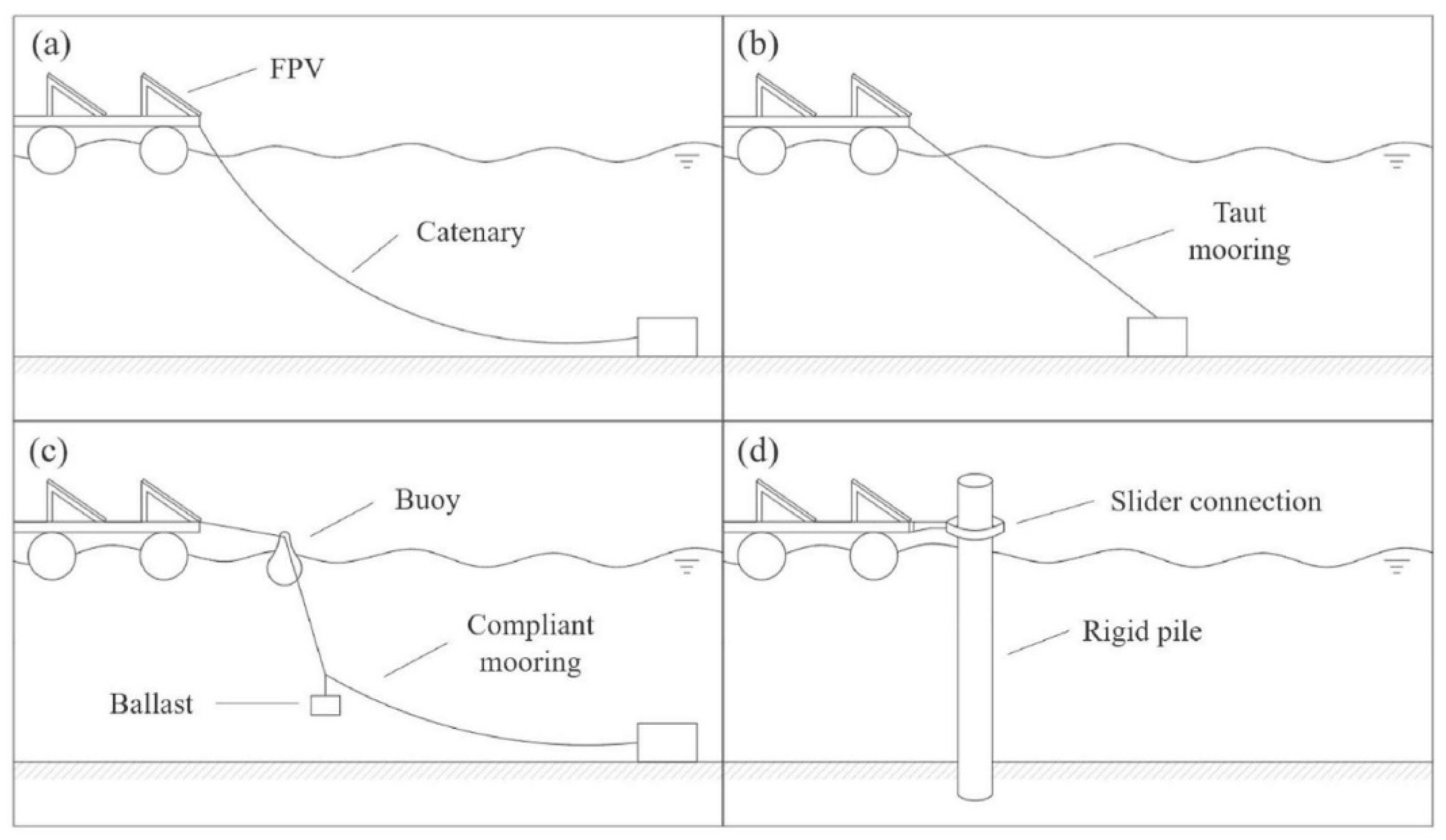
Mooring systems are crucial for stabilising FPV installations, particularly in offshore environments where high wave loads and strong currents pose structural risks. These systems keep the installations in position while allowing some movement for the floats to counter currents, waves, and wind action [15,50,53]. The mooring cables of floating PV installations mainly consist of galvanised steel wires, chains, wire rope, synthetic fibre rope, elastic rubber hawsers, or a combination of materials [50]. Figure 10 [53] presents the most common mooring techniques, including catenary, taut, compliant, and rigid piles, each with distinct advantages depending on depth and wave conditions.
Taut mooring systems are currently the most used for OFPV installations, such as the HelioSea concept [54] and SolarinBlue’s Sun’Sète [42]. However, other mooring systems that have not been widely adopted could potentially be effective. The Solaqua design has tested mainly catenary moorings [36], while the CGN Yantai Zhaoyuan installation uses rigid piles [55]. Indeed, mooring systems are also used in other industries such as offshore oil and gas or wind energy.
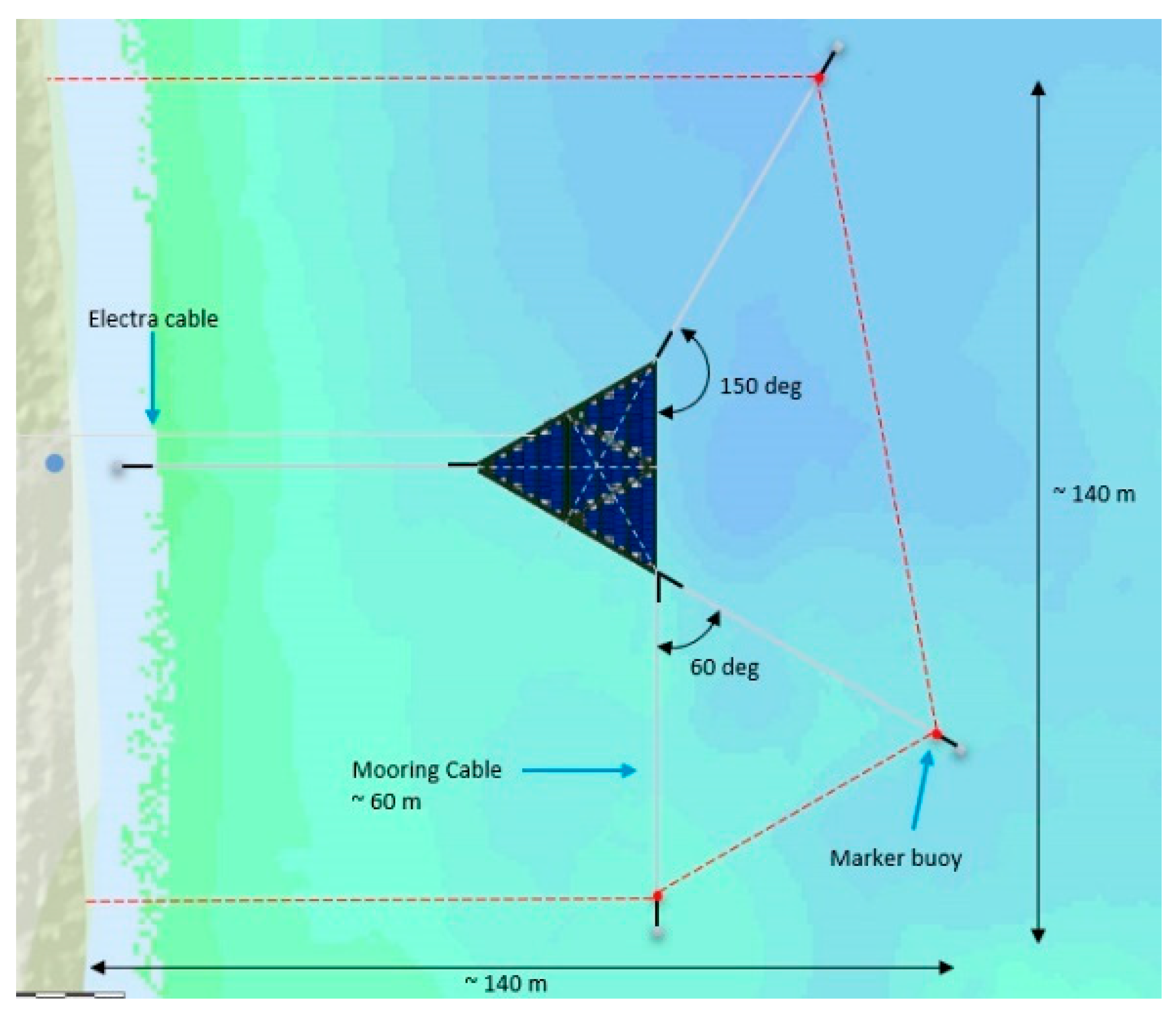
Suction piles are associated with oil platforms and offshore wind, but their potential for deep-water OFPV installation exists, especially on a soft seabed. They consist of long steel cylinders with a pile or a cap on the top lowered to the seabed. This technology has been used as a mooring anchor since the 1990s [56]. SolarDuck uses a mooring configuration that requires low mooring forces as a result of the floater design. The 60 m mooring cables are situated around all edges of the platform to provide stability, as shown in Figure 11 [45]. In its other prototype, Merganser, SolarDuck utilises a catenary system incorporating buoyancy elements [57]. The mooring system is arranged in a spread mooring layout, featuring two mooring lines on each side of the hexagonal structure. The system employs conventional drag anchors connected to a short length of chain, buoyancy elements, and polyester mooring lines. For future designs, SolarDuck is looking to further optimise the mooring configurations.
The connectors between multi-platform OFPVs have an effect on the hydrodynamic performance of the system while directly affecting the tension on the mooring lines [58,59,60]. Furthermore, a bad connector design can become the failure point of the entire FPV system. Yan et al. [59] performed a hydrodynamic analysis on multi-platform OFPVs using rigid and hinged connectors. Some of the conclusions of this study were that hinged connectors resulted in a significant dynamic response to sway, roll, and pitch due to additional moments generated by the joint of the connector. Furthermore, hinged connectors resulted in greater mooring tension. Another study [61] proposes a new design of a flexible-base hinged connector (FBHC) and compares it to a rigid hinged connector (RHC). The proposed connector is composed of two flexible bases and a hinged joint. The results show that the FBHC resulted in lower connector loads. Ji et al. [60] carried out a study on three different connector configurations involving fenders, rubber rings, and ball joints. The configuration with ball joints aligned with the direction of wave propagation proved to be the most adequate at reducing rotational responses of the OFPVs.

4.4. PV Module Technologies

While various PV module technologies exist, these can be divided into two main categories: monofacial and bifacial. In their study, Hasan et al. [62] analysed the use of bifacial photovoltaic panels for offshore energy production. They proposed a system modelled and simulated under various water conditions using COMSOL Multiphysics. The system’s performance was evaluated by simulating a bifacial PV module on a floater covered with aluminium sheets. The study’s results show that, compared to monofacial panels, bifacial photovoltaic modules have maximum and minimum energy efficiency gains of 11.9% and 2.8%, respectively. In addition, north/south-facing modules experienced a maximum increase of 55% in solar irradiance exposure compared to monofacial panel operating on the same water surface. East/west-facing modules experienced an increase of 31% in irradiance exposure when operating on the water surface. Where wave conditions were added, the maximum increase in irradiance was 49% (N/S) and 33% (E/W). Another study by Tina et al. [63] showed that energy production can increase by up to 13.5% when fixed-tilt bifacial panels are installed.
Recently, the company Grand Sunergy [55] introduced their Seapower series, consisting of new PV modules specially designed for offshore applications. The bifacial module comprises a double glass with a peak power of 730 W and an efficiency of 23.5%. According to the company, the modules adopt “210 mm large-size heterojunction (HJT) cells, double-layer coated glass, UV-resistant encapsulation film, high-resistance water-sealing butyl rubber edge sealing, waterproof and salt spray-resistant junction box, and dust-proof cover connectors”. Grand Sunergy claims that these processes and materials enhance the glass’s weather resistance, improve the water resistance, increase the module’s light utilisation rate, eliminate power attenuation caused by strong UV light, and reduce water permeability by 99.9% compared to industry standards.
SolarinBlue’s Sun’Sète uses bifacial glass–glass PV modules with a salt mist certification and more than 24.5% efficiency [42]. On the other hand, SolarDuck [45] utilises common off-the-shelf PV modules installed with an east–west orientation for optimal power output per area.
In addition, Matthias Herberich and Farshid Ebrahami [64] describe the concept of a “Tube module” consisting of PVT evacuated tubes floating on water. They claim that their round shape helps reduce potential snow load and wind and wave surface attack. However, this design is still in its early stages, and one must see if the fragile components will withstand harsh offshore environments.

Effect of Oxidation and Microstructural Evolution on Photovoltaic Thin Films

Oxidation profoundly affects carrier transport in thin-film photovoltaic materials, such as Copper–Indium–Gallium–Diselenide (CIGS). CIGS solar cells typically suffer from high recombination losses at interfaces. Achieving stable, efficient operation requires controlling these losses, often via dielectric passivation layers. A suitable thermal annealing process is mandatory to “activate” this passivation by initiating restructuring and controlled oxidation of the CIGS surface. While controlled oxidation is beneficial, exposure to oxygen and excessive thermal stresses without adequate control can be detrimental. The extreme sensitivity of CIGS surfaces to their oxidation state suggests that uncontrolled environmental factors (such as constant humidity and salt aerosols common in offshore conditions) would require robust encapsulation to prevent detrimental surface or bulk oxidation mechanisms from dominating device performance [65].
The interaction of PV materials with oxygen or air also changes their microstructure, which directly impacts their optical properties and mechanical stress tolerance. The micromorphology and surface topography of materials like Cadmium Telluride (CdTe) are quantitatively altered during oxidation (exposure to air). Oxidation increases the complexity and irregularity of the surface. The fractal dimension, which increases as the roughness exponent decreases, measures this total profile complexity and influences light scattering on structural elements. Uncontrolled surface oxidation, typical of harsh environments, is correlated with worse stoichiometry and larger fractal dimension [66]. Changes in the surface structure and the growth of oxide layers can contribute to stress between the PV material (monocrystal) and the thin oxide layer, detectable via shifts in phonon peaks during Raman spectroscopy. Long-term exposure to corrosive elements in offshore environments would likely accelerate such microstructural changes and internal stress, potentially compromising overall device stability [66].

4.5. Energy Storage Systems

Energy storage plays a critical role in FPV system scalability. Based on a dialogue with relevant stakeholders, Arellano-Prieto et al. [67] identified the opportunities and challenges of offshore energy storage systems:
  • One challenge of offshore storage systems is to deal with a lack of space and weight constraints.
  • Offshore energy storage systems must include black start, continuous voltage support, and frequency regulation features.
  • The design must be optimised to require as little maintenance as possible to limit high operational costs.
  • If the supply does not match the yearly demand, seasonal storage is necessary.
Various energy storage solutions exist. This section reviews the most promising ones identified in the literature with potential for offshore applications:
Batteries: Batteries are by far the most common energy storage technology and have recently become synonymous with GPV installations [15,67,68]. Many types of batteries are available today with different chemical combinations such as lead–acid, lithium ion (Li ion), lithium iron phosphate (LiFePO4), nickel–cadmium (Ni-Cd), and sodium–sulfur. In general, batteries have a high readiness level, high integrability, low maintenance, and high efficiency. However, some technologies have very low energy densities, and their environmental impact can be very high [69].
Hydrogen: There are four main types of hydrogen storage technologies, which are hydrogen stored in metal hydride, hydrogen compressed in a tank, hydrogen liquefied in a tank, and hydrogen storage underground. Green hydrogen is considered to be a sustainable fuel, with climate-neutral production [15,70]. Hydrogen storage technologies can have high energy densities and can have a very low environmental impact; however, these technologies have low efficiency and integrability and require advanced and expensive infrastructure [71].
Compressed Air Energy Storage (CAES): Compressed Air Energy Storage involves pumping air into geological reservoirs or storage vessels. This allows energy storage at low cost for a long period of time. This technology has a high readiness level, a long discharge duration, and an incredibly low environmental impact; however, its energy density is very low [67,69,72].
Flywheels (FESSs): Flywheels are accelerated to store energy and decelerated to use the stored energy, with the aid of an electrical motor/generator [73]. This technology has low energy density but a low environmental impact and high power density, readiness level, response time, efficiency, and safety [67].
Supercapacitors: Supercapacitors have a very low energy density, low capacity, and a high environmental impact. Furthermore, their high capital cost [69] makes them inadequate for large-scale storage. However, their maintenance is simple, and their response time is high.
Ammonia fuel: Ammonia fuel is characterised by a remarkably long discharge duration and a good capacity. Furthermore, it has a higher volumetric density than hydrogen and requires more simple storage infrastructure. However, ammonia has very low gravimetric energy, pushing research more towards ammonia-carried hydrogen rather than using it directly as a fuel [74,75,76,77].
Hydro-pneumatic energy: Hydro-pneumatic energy has very low energy density and a low readiness level, but its efficiency is very high, and its environmental impact is very low. For example, the “FLASC”, Floating Liquid-piston Accumulator, uses positive-displacement pumps to compress air in isothermal conditions thanks to a submerged storage vessel [78,79]. This system can be integrated with offshore energy generators, taking advantage of the offshore environment to improve the system’s efficiency. It is also designed to operate with minimal pressure fluctuations.
In a study [67], the technical characteristics of eleven energy storage solutions were evaluated, covering four battery types and four hydrogen storage technologies. The analysis considered multiple performance indicators, including the energy content per unit area, mass–energy density, storage capacity, duration of discharge, response time, efficiency, safety and environmental impact, maintenance needs, ease of integration, and technology readiness level (TRL). Two scenarios were tested: reaching a 40% renewable energy share by 2030 and reaching a 100% renewable energy share by 2050. The results showed that for the first scenario, Li-ion batteries and CAES were the most promising technologies due to their readiness level and integrability. The results for the second scenario showed that a hybrid storage system could be effective in overcoming the current low maturity of the technologies.
According to the authors of this review, the ideal offshore energy storage technology would not involve any moving parts to decrease maintenance costs in a highly corrosive environment. Furthermore, the choice of energy storage technology should also be site-dependent. For example, hydro-pneumatic energy is ideal for intermittent power generators such as wind turbines or PVs installed in locations with high weather variability. Likewise, batteries are ideal for sites with better weather predictability since one would have more control of the charging and discharging cycles, thus optimising the system to increase its lifetime while fulfilling any grid requirements. Table A2 presents a comparison of select technical performance and operational metrics for energy storage technologies relevant to offshore applications. Among the reviewed technologies, CAES and hydro-pneumatic systems are best suited for deep-water OFPVs because they exploit hydrostatic pressure as a natural storage medium, minimising moving components exposed to corrosion. Conversely, battery systems require sealed housings and temperature control and thus are more suitable for nearshore or platform-mounted FPVs. Ammonia and hydrogen storage provide higher energy density and can serve as exportable fuels, yet their low round-trip efficiency restricts adoption in large integrated energy hubs. Therefore, site bathymetry, salinity, and maintenance accessibility dictate the optimal FPV storage technology.

5. Selected Case Studies and Field Deployments

5.1. Overview of Recent FPV Projects Worldwide

Floating and offshore solar PVs are becoming increasingly popular due to the benefits they offer compared to GPV systems. Numerous installations have been launched worldwide recently, demonstrating the technology’s potential and resilience. In 2021, more than 3 GW of FPV systems were installed worldwide, while in 2022, most of the growth was in the Asia–Pacific region with large-scale projects (over 50 MW) installed in China and India. Smaller-scale projects were commissioned in Tunisia and in Europe, specifically in France, Portugal, and the Netherlands [24]. This section aims to explore a select number of installations from different continents, showcasing recent advancements in floating technologies.
In August 2024, China’s first large-scale OPV pile-mounted project was energised for the first time. Located in Laizhou Bay in northern Zhaoyuan City, the CGN Yantai Zhaoyuan 400 MW project includes 121 PV sub-arrays (totalling more than 539 MWp) and extends over 6.44 square kilometres. The installation consists of Grand Sunergy’s 710 W OPV modules. These PV modules are bifacial, have a double-glass, and use high-efficiency heterojunction (HJT) solar cells [40,55,80,81]. The project has an expected average annual electricity output generation of 690 million kWh over an operating period of 25 years; it would produce the annual electricity needs of around 400,000 households. Therefore, this project would allow for a reduction in “coal consumption by about 207,000 tons per year and carbon dioxide emissions by about 532,000 tons per year” [55]. With more than 18,000 kilometres of coastline and a 1800-square-kilometre area where pile-based OPV can be installed, China could theoretically install more than 100 GW of OPV [82].
In Fuyang, Anhui Province, 122 PV array matrices are combined for a total capacity of 650 MW, containing 1,200,000 PV panels. The mean water depth of this location is 8 m, and the maximum depth is 20 m. In an LFPV installation in Peixian, Jiangsu Province, an HDPE pontoon is employed. Steel cables and spiral piles were used for mooring while allowing for a 5 m variation in the water level. PV modules were installed at an angle of 12 degrees to allow heat dissipation while reducing the wind load [83]. The total capacity of this installation is 72 MW, covering a water area of 3.9 square kilometres. A PV installation angle of 15 degrees was chosen, and the system is designed for wind velocities of up to 25 m/s. Aluminium alloy support legs were used to reduce costs, while magnesium-plated aluminium–zinc alloy track brackets were used to provide high corrosion resistance. Pile anchoring was adopted for this system. Furthermore, anchors and elastic ropes were used to allow the system to adapt to water level changes [84]. In Liaocheng, Shandong Province, more than 370,000 LONGI Hi-MO 5 PV modules are combined for a capacity of 202 MW. These bifacial PV modules are encapsulated on both sides with glass to provide better weather resistance. Furthermore, an advanced encapsulation process is employed on the front side, reducing water vapor permeability and therefore increasing the material’s stability and extending the lifetime of the modules [85].
Recently, HelioRec [86], a French-based start-up, installed an innovative floating solar PV project in Brest Port, in the Bretagne region, France. Brest is known for its extreme tidal changes and its extreme winds that can exceed 100 km/h, leading to very high waves. HelioRec designed and built a floating solar unit with a total capacity of 25 kW that resists these extreme weather conditions.
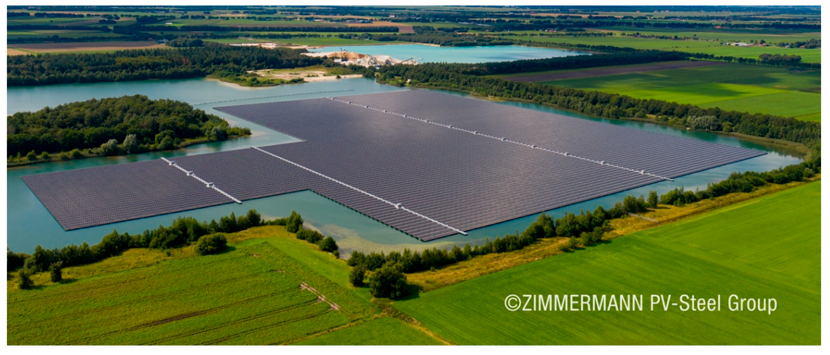
Located in Groningen, the Netherlands, the Sellingen floating Solar PV Park was developed by GroenLeven [87] in a record time of nine weeks [88]. The construction of the project began in 2021 with a total capacity of 41.4 MW. The installation generates 34,000 MWh of electricity, enough to power 12,000 households. The project, represented in Figure 12 [87], covers 22.54 hectares and includes 76,616 PV modules. It uses the ZIM Float System developed by the company Zimmermann PV-Floating [89].

5.2. Reported Incidents

Like every technology, floating and offshore PV installations come with a number of risks. In some projects, there have been reported incidents that provide important lessons to take into consideration for future deployments:
  • In September 2019, Typhoon Faxai, one of the strongest typhoons ever recorded, impacted Tokyo’s metropolitan area [90], causing considerable damage along the coast of Tokyo Bay. Faxai’s 54 m/s winds caused a Japanese floating solar plant to catch fire as a result of floaters piling on each other. The installation was floating on an inland water body, specifically on top of the Yamakura dam. As the wind and waves flung panels together, a combination of short circuits, DC arcs, and overheating led to a destructive fire [50].
  • Also in 2019, a localised tornado hit the Netherlands and flipped some arrays of floats and PV modules onto each other [50].
In both cases, damage was caused due to the flipping over of periphery rows of PVs. According to a handbook for floating solar practitioners [50], the potential causes for such incidents could be attributed to the following:
  • Anchor points positioned a few rows inside the floating array and not at the perimeter floats.
  • Perimeter floats are not left empty. Installed PV modules on these floats can capture uplift forces.
  • A low water level preventing the mooring cables from effectively absorbing the wind load.
  • Larger wave heights than predicted.
  • The sudden tensioning of slack mooring lines created peak forces which led to damage to the mooring attachment point.
Some design optimisations can help to prevent the platforms from flipping over. These include a dual-orientation PV configuration so as to limit the exposure of inclined PVs to wind forces, allowing a one-row perimeter of empty floats around the floating array, or the installation of windshields behind the perimeter panels. Furthermore, correct mooring of peripheral rafts should be considered to potentially avoid such incidents.
Another incident was reported concerning an OFPV demonstrator in Haiyang City in Shandong Province, where the PV modules went missing. The installation consisted of Ocean Sun’s patented technology [31]. According to an expert analysis, the PVs most likely sank to the bottom of the sea. The wave height in the installation area is mostly above 6 metres, resulting in overtopping and filling of the bottom membrane with water. Furthermore, the expert report states that the system was not equipped with a water drainage pump as planned, which could result in the overtopping water breaking the membrane. Moreover, the frameless photovoltaic modules used for the installation are prone to breakage due to waves. This could also lead to the rupturing of the membrane underneath. However, no official report was released by the State Power Investment Corporation [91].
In June 2021, another 0.5 MW floating solar unit installed by Ocean Sun in collaboration with Statkraft at the Banja reservoir in Albania experienced significant damage. The floating ring and two connected barges were severely damaged and partially submerged due to weather conditions exceeding the design’s wind speed criteria. Ocean Sun conducted a root cause analysis, attributing the failure to these unexpected weather conditions, and implemented design modifications for future resilience [92].
In March 2023, a large floating PV array, comprising over 100 interconnected solar panels, mysteriously washed up on the beaches of Sha Chau and Lung Kwu Chau Marine Park near Hong Kong. A local environmental group, Kitti Green World, documented the event, and authorities initiated an investigation to determine the array’s origin. While some speculated illegal dumping, it is more plausible that the system lost its anchoring and drifted due to sea currents [93].
These incidents underscore the challenges faced by OFPV installations, particularly concerning anchoring systems and resilience to harsh marine environments. They highlight the importance of rigorous design standards and environmental assessments in the deployment of such renewable energy technologies.

6. Challenges and Opportunities

6.1. Performance Comparison

The energy yield can vary considerably between OFPV systems, LFPVs, and GPVs. In their study, Golroodbari et al. [94] developed a model to determine the potential energy yield from OFPV systems, by comparing twenty different locations across the globe with varying climates [94]. The results showed that the energy yield from OFPVs can be significantly higher compared to GPV systems in some places, with differences of +20% to −4% depending on environmental conditions. The increase in the energy yield can be mainly attributed to the cooling effect of the water [4]. This cooling effect lowers the temperature of floating and offshore PVs, thus increasing their performance. However, these advantages are influenced by many factors, such as sea surface temperature, wind speed, and solar radiation. Golroodbari et al. [94] also showed that LFPVs also benefit from the cooling effect but are more stable than OPVs or OFPVs because they are less exposed to harsh weather conditions. It has been shown that OPV and OFPV systems have a higher energy yield than LFPV systems, but the importance of this increase is site-dependent. Moreover, the performance of LFPVs can also be influenced by humidity, local wind, and the design of these systems. For example, some technologies such as HDPE pontoons or galvanised steel frames can lead to various levels of energy yield ranging from 0.31% to 2.59% depending on the technology used [94]. The choice between OFPV systems, LFPVs, and GPV systems should be made considering geographical factors such as land availability and the local climate but also the characteristics of water bodies.

6.2. Technical Challenges

As discussed earlier, OPV installations come with their own set of challenges. In order to install a reliable long-lasting efficient system, accurate prediction and system optimisation are a very important aspect of these challenges.
Non-tracking photovoltaics are installed on land with fixed tilt and orientation angles. However, when installed offshore, wave movements will cause these angles to change, having some impact on the energy yield. In their studies, Bugeja et al. [34,95,96] developed an “Offshore Solar Irradiance Calculator” (OSIC), a simulation tool designed to analyse the impact of wave response motion on OFPV systems. The software allows a system designer to enter characteristic equations representing the designed float’s response to common wave profiles found in the installation area. Hence, the software will output the expected effect on the irradiance incident on the photovoltaic modules. This would allow the designer to make necessary adjustments to limit some movements, such as adjusting the tension of the mooring cables. These studies included parametric analyses of these effects on fixed installations, vertical single-axis trackers (VSATs), horizontal single-axis trackers (HSATs), and dual-axis tracking photovoltaic systems. OFPV tracking systems like the HelioSea concept [37] have to keep this effect in mind since it will also affect the tracking algorithm, making it more difficult in a constantly moving environment.
Floating PV systems might have superior structures to the conventional structures installed on the ground or on rooftops. However, there are several challenges that this type of technology faces. The most challenging aspect concerns the design of the unit, which must be performed in such a way that the system can withstand extreme weather conditions and stay afloat. The following issues should be addressed while implementing a floating solar plant [1]:
  • A high moisture content from the water surroundings may accelerate degradation of the solar modules and deteriorate structure strength. SolarinBlue [42] have mitigated this by using PV modules that are resistant to salt mist. Other companies such as Sunergy [81] are producing PV modules that are salt-mist-resistant, designed specifically for offshore installations.
  • Durability and survivability of materials used for power transmission from the floating installation to the land area.
  • The annual fluctuations in a reservoir’s water level or tide. Mooring systems need to be able to adapt to these possible fluctuations.
  • In the marine environment, the installation would be exposed to the overall climate of the sea, including salt, as well as subjected to mechanical loading challenges that arise from the dynamics of wind and waves and tidal regimes [14].
  • A high installation cost is not often an investment that will pay back over time but rather becomes an economic concern that restrains expansion of the floating technology on the market. This is further accentuated by economic concerns associated with maintenance.
  • There could be environmental and aesthetic concerns, as third parties might not be fully familiar with this type of technology; therefore, concept propagation and careful planning is required to gain public acceptance.
Finally, OPV systems share several structural and environmental challenges with offshore wind farms. Similar to offshore wind farms, the continuous movement due to waves, currents, and wind forces can lead to important stresses on the mechanical and electrical components of PV systems. Concerning offshore wind systems, studies have shown that failure rates for mechanical components such as mooring lines are influenced by several environmental factors such as corrosion, biofouling, and fatigue due to repetitive loading [97]. Similar challenges can be expected for OFPV systems where the resistance of mooring lines is crucial to maintaining stable and continuous energy production.

6.3. Regulatory and Standardisation Issues

Since OPVs are still an emerging technology, there is a need for international standards and regulations concerning offshore and floating PVs. These technologies are complex and concern multiple sectors such as energy, water management, environmental protection, and maritime activities.
OFPVs do not have unified standards yet, unlike GPVs. Concerning the environmental and ecological aspects, regulations must be set to protect marine ecosystems and water quality. Some mandatory assessments for offshore energy projects already exist but are not exclusive to the unique characteristics of OPVs. Without clear regulations, the development of this technology could lead to potential project shutdowns due to impacting marine or freshwater ecosystems.
The standards IEC61701 [98] and IEC60068-2-5 [99] already describe test sequences to evaluate the resistance of photovoltaic modules to corrosion from salts. Standards such as IEC61730-1 [100] should be revised to cover the construction of photovoltaic modules specifically designed for offshore environments. DNV has published the recommendation practice DNVGL-RP-0584 titled “Design, development and operation of floating solar photovoltaic systems” [101]. However, this guideline is suitable in the case of LFPVs or OFPVs in coastal areas with mild sea conditions and a wave height of less than 2 m. Therefore, specific design guidelines for OFPVs are still missing.

6.4. Economic Feasibility and Market Potential

Although FPVs outperform traditional PV systems in terms of energy production, their installation costs have been reported to exceed USD 100,000 per MWp. As a result, it is stated that the main disadvantage of FPV systems is their high cost [17]. The economic viability of FPV systems is influenced by factors such as capital investment, operational expenses, and energy production. In the Abu Dhabi case study, the total cost of a floating PV system was estimated at approximately USD 2.56 million. The Levelised Cost of Electricity (LCOE) ranged from 261 to 349 USD/MWh, aligning with similar off-grid solar PV projects in regions like Indonesia. The Net Present Value (NPV) was positive, and the Discounted Payback Period (DPP) was less than 10 years, indicating economic feasibility [18].
In Aotearoa—New Zealand—an assessment of a 10 MW LFPV installation projected an annual energy output of between 1115 and 1497 kWh/kWp. The LCOE was estimated to be between NZD 176 and NZD 237 per MWh. To achieve a more competitive LCOE below 100 NZD/MWh, the study suggested that Engineering, Procurement, and Construction (EPC) costs would need to be reduced by approximately 50% to around 1500 NZD/kWp [102]. A techno-economic analysis of a 10 MW LFPV plant [103] demonstrated a 10.2% higher energy generation compared to GPV systems, resulting in an additional 28.38 million units over the plant’s life cycle. The LFPV installation also conserved land costs amounting to USD 352,125 and water cess charges of USD 47,600. Consequently, the LCOE for the LFPV plant was reduced to 0.026 USD/kWh, approximately 39% lower than that of GPV systems.
Experimental assessments comparing LFPV systems to conventional GPV installations in Mediterranean climates have revealed notable findings. Adjusting the LFPV tilt to 10° reduced module temperatures by 7.24 °C, leading to a 16% decrease compared to GPV systems. This configuration also reduced evaporation by 83.33% and increased power generation by 8.92%. The study confirmed that the LFPV system produced electricity at an LCOE of 0.059 USD/kWh [9].
According to a report conducted by the Fraunhofer Institute for Solar Energy Systems, the potential for LFPV installation in Germany is approximately 56 GW. The installation cost of LFPVs is 10–15% higher than that of traditional PVs. This obstacle hinders the growth of LFPV systems, which could be addressed through incentive packages [104]. This study analysed the cost breakdown of components forming utility-scale GPV installations. The total cost was broken down into five sections:
  • PV modules: 31% of the total cost;
  • Balance-of-System (BoS) hardware: 23% of the total cost;
  • Installation: 20% of the total cost;
  • Soft costs: 20% of the total cost;
  • Inverters: 6% of the total cost.
The results of their analysis also showed that each time the cumulative PV module production doubled, the module price dropped by about 24.4% over the past 43 years.
A key component to achieving economic feasibility for OFPVs is reducing the price of the material making up the floats. This is already being conducted for LFPVs with the use of HDPE and MDPE platforms as well as bamboo-based composite materials [46,105].

Techno-Economic Assessment

The specialised nature of FPV installations results in higher upfront capital costs (CAPEX) compared to GPVs [106]. The initial capital investment for FPVs is typically reported to be 25% to 30% higher than that for GPV systems, largely due to the necessity of incorporating floating structures and robust anchoring/mooring components [106,107].
The Levelised Cost of Electricity (LCOE) is the primary metric used to assess the economic viability of FPV projects, representing the average total cost of electricity generation per unit over the system’s lifetime [107,108,109]. Globally, LFPV systems reported LCOE values ranging from 0.05 to 0.15 USD/kWh during the period 2013–2023 [110]. The LCOE values for LFPVs are increasingly competitive. For instance, a techno-economic analysis for a 1 MW LFPV system in India (25-year lifespan) found an LCOE of 0.0551 USD/kWh under standard maintenance conditions, which is comparable to the 0.0529 USD/kWh calculated for a similar GPV system [107]. Other studies cite LFPV LCOE values in India as low as 26 USD/MWh (0.026 USD/kWh) [108]. For LFPV systems deployed in U.S. markets (based on Q1 2021 cost data), a benchmark study estimated the LCOE at approximately 56.6 USD/MWh without the Investment Tax Credit (ITC) and 37.8 USD/MWh with the ITC. In this specific comparison, the LFPV LCOE was approximately 20% higher than the LCOE of GPVs [111].
OFPV systems generally exhibit a higher LCOE due to increased structural and installation complexities arising from harsher environmental conditions. A comparative assessment of offshore fixed and floating systems in Hainan, China, found that floating systems had an LCOE ranging from 152 USD/MWh to 1253 USD/MWh (for water depths up to 200 m). These floating systems show low sensitivity to water depth and distance, making them suitable for large-scale deployment. In contrast, fixed offshore PV systems were competitive in shallow waters (up to 30 m deep), showing an optimal LCOE range of 81.2 USD/MWh to 293 USD/MWh [108]. In a techno-economic feasibility study for a battery-integrated OFPV system designed for an offshore oil platform in Abu Dhabi (25-year project lifespan), the optimised solution achieved an LCOE of 261 USD/MWh [18]. For remote islands in Indonesia, a hybrid system combining OFPVs, a Wave Energy Converter (WEC), and battery storage (Scenario 1, 25-year lifespan, 2024 methodology) resulted in an LCOE of 306 USD/MWh, while an OFPV-only system (Scenario 2) reached 382 USD/MWh [108].
The initial investment (CAPEX) for FPV projects varies widely, typically ranging between 0.7 and 2.0 USD/Wp globally [110]. The high structural costs associated with the floats and the anchoring/mooring system constitute the largest portion of the FPV cost premium [111]. Table 2 summarises the key techno-economic parameters of FPV projects in different locations globally.

6.5. Environmental Impact

Solar energy is considered as one of the most environmentally friendly energy sources [115]. However, deploying offshore renewable energy systems impacts marine ecosystems, including sea life. Floating photovoltaic arrays can have several environmental impacts such as shading, water–atmosphere exchange, impacts on hydrodynamics, and impacts on various species [116]. Assessing and mitigating these impacts is crucial to ensuring the sustainability of these projects. This section investigates the ecological footprint of FPV systems, emphasising their benefits and potential effects on aquatic ecosystems.

6.5.1. Positive Impacts

Reducing reservoir water evaporation is one of LFPV systems’ many noteworthy environmental advantages. Research conducted in Australia [8] has indicated that evaporation can cause up to 40% of the water in open tanks to be lost. Merely 30% of the water’s surface can be covered with photovoltaic panels to minimise evaporation by roughly 49%. This reduction is especially important in dry climates and agricultural areas where conserving water is essential.
Furthermore, LFPV systems help in regulating the growth of algae [117]. Algae blooms can be detrimental to fish populations and aquatic environments. Since the floating panels shade the area underneath, less sunlight penetrates. Algae naturally need light because photosynthesis cannot occur in the dark. Therefore, by blocking the sunlight, the PV modules block the growth of algae. The combined advantages of reducing algae growth and conserving water can improve the ecological sustainability of LFPV installations.
FPV installations contribute to a reduction in the use of fossil fuels and, consequently, a decrease in CO2 emissions by producing clean, renewable energy. This contribution emphasises the significance of renewable energy in the fight against climate change and is in line with the European Union’s initiatives to reach carbon neutrality by 2050 [14,19,20] and the Nationally Determined Contributions (NDCs) requested by the Paris Agreement [118].
The components of FPV systems can be made with environmental sustainability in mind. The floating platforms can made of high-density polyethylene (HDPE), which is extremely resilient, impervious to corrosion and UV radiation, and recyclable up to one hundred times. Because of their recyclability, FPV systems have a minimal ecological footprint throughout their lifetime.

6.5.2. Potential Ecological Concerns

It is imperative, nevertheless, to consider the possible negative effects on aquatic ecosystems. Although the shading effect helps reduce the number of algae, it can change the surrounding habitat for aquatic plants and animals by reducing dissolved oxygen levels and altering water temperatures [14,119]. For FPV installations to not negatively impact biodiversity, ongoing environmental monitoring and impact assessments are required.
Seabed contact from mooring systems is a crucial design parameter that influences benthic impact. Heavy catenary or drag–embedment moorings, by design, affect a larger sea floor area (the “touchdown area”) than taut systems, potentially leading to disturbance and resuspension of (in)organic matter [119]. Furthermore, submerged structures, including floaters and mooring lines, provide a new substrate for marine growth. Observations from a North Sea demonstrator recorded rapid colonisation of submerged structures by macro-fouling organisms, notably the blue mussel (Mytilus edulis) [120,121]. These suspension feeders play a key role in the production of organic matter (OM) through the excretion of faeces. While this bio-deposition creates the potential for enhanced organic-matter export to the seabed, initial monitoring [121] of the sediment underneath the FPV installation (after 18 months) did not detect an enrichment in carbon and nitrogen compared to surrounding areas. Therefore, design choice is critical since taut-leg or suction-pile systems that minimise the seabed contact area can mitigate sediment disturbance risks [119].
According to Schneider et al. [119], two main changes occur when OPVs are installed in a marine ecosystem. Firstly, air–sea interactions are blocked, such as solar radiation and wind. Moreover, a new substrate is introduced into a previously unobstructed environment because of floaters and mooring lines. These changes can potentially influence currents and also reduce the population of primary producers, organisms that draw their energy from sunlight and materials from non-living sources. Phytoplankton are amongst the affected primary producers. These organisms produce a large part of the oxygen in the atmosphere and form a crucial part of the ocean food chain [122]. This could therefore affect the food availability for all organisms, even at higher trophic levels. Large OPV installations can also affect the temperature of the sea due to an impact on hydrodynamics and heat exchange. This happens mainly due to floaters and anchors obstructing currents and limiting the heat exchange between the ocean and the atmosphere [119,123]. Photovoltaic modules installed very close to or in contact with the water surface can also limit the dissolved oxygen concentration of the water body underneath due to the impact on the air–water interface [124,125,126].
Empirical and modelling studies provide quantitative confirmation of these effects. In small experimental ponds where floating solar arrays covered approximately 70% of the surface, Ray et al. [127] measured a 26.8 ± 20.2% rise in whole-pond GHG emissions, nearly doubling CH4 ebullition rates, and a significant decrease in gas-transfer velocity (k600), confirming that high coverage restricts air–water exchange and reduces near-surface dissolved oxygen. A multi-study synthesis [128] reported similar patterns, showing significant dissolved oxygen (DO) decreases under panels, but negligible nutrient effects were observed when the coverage was maintained below approximately 50%. Field data from 26 water-surface PV installations in the Yangtze basin [129] further confirmed lower DO saturation and temperature within photovoltaic areas. Collectively, these findings show that the coverage ratio is the principal design parameter governing DO and temperature responses, with marked effects often emerging above roughly 50% surface occupation. Finally, the maintenance of floating photovoltaics can contaminate aquatic bodies due to the use of chemicals and cleaning agents [119,130].

6.5.3. Mitigation Strategies

The ecological footprint of FPV systems can be minimised through integration with other renewable energy technologies and water management strategies, guaranteeing a positive contribution to the renewable energy environment.
It is crucial to collect more data on the environmental impact of floating and OPVs to ensure a functioning ecosystem. According to Schneider et al. [119], the location of OPVs should be selected to avoid fragile habitats, coral reefs, seagrass beds, and kelp forests. Moreover, potential environmental impacts should be a main factor when designing an OPV system, and some design considerations should be taken into account, such as the following:
  • The area blocking the sunlight should be minimised. This can be achieved by allowing light to pass between rows of panels.
  • The coverage ratio should be optimised to allow surrounding waters to dilute and/or compensate for potential environmental impacts.
  • The contact area with the water should be minimised to reduce the risks of leaching and biofouling and reduce the effect on the air–water exchange.
  • The “contact zone” of mooring lines should be kept to a minimum to reduce the disturbance of the seabed and the resuspension of (in)organic matter.
  • Materials should be selected to minimise the potential for releasing toxic substances, such as chemicals, metals, oils or plastics, into the marine environment through leaching or leakage. Any chemicals used for routine cleaning should also be carefully selected.
  • Dry transformers should be used to eliminate the risk of oil leaks.
Overall, comparative evidence suggests that the success of FPV deployment depends on the maturity of anchoring systems, corrosion-resistant materials, and cost reduction through mass production. The main unresolved gaps are as follows:
  • Limited long-term field performance data under variable hydrodynamic loading;
  • Insufficient integration of techno-economic modelling with Environmental Impact Assessment;
  • Lack of control strategies for hybrid FPV–storage systems.
Quantitative analyses [128] recommend maintaining a panel coverage of ≤40–50% on deep or well-mixed reservoirs until long-term data confirm minimal dissolved oxygen and trophic alteration. Where higher densities are required, design measures such as alternating open-water lanes or utilising variable-height layouts can preserve mixing and oxygen diffusion [119]. Future research should therefore focus on multi-objective optimisation frameworks that simultaneously address structural durability, cost, and ecological sustainability.

6.5.4. Material and Life Cycle Considerations

Material selection for floaters and mounting structures strongly affects both the life cycle environmental burden and ecotoxicological performance. A detailed Life Cycle Assessment (LCA) of a 150 MW FPV system in Thailand [131], spanning a 30-year lifetime, estimated significant resource consumption: approximately 73 kg of greenhouse gases (CO2-eq) per MWh produced and ≈110 m3 of water consumed per MWh. The environmental burden is highly dependent on design material choices. For instance, water consumption was primarily driven by the production processes (extrusion and purification) required for the aluminium used in the mounting/support system.
In terms of ecotoxicology, the manufacturing of floats and mounting systems contributed almost exclusively to terrestrial and marine ecotoxicity impacts measured in the LCA [131]. Additionally, operational use introduces risks: material selection is critical, as galvanised steel or certain antifouling coatings may leach toxic substances such as zinc, nickel, and chrome into the water [119]. Although FPV floats are often made of high-density polyethylene (HDPE), which is resilient and recyclable, it is vital that the chosen materials minimise the potential for releasing toxic substances (chemicals, metals, or plastics) into the marine environment through leaching or leakage.

7. Integration of FPVs with Other Technologies

According to Cazzaniga et al. [10], there is significant interest in deploying LFPV systems in conjunction with hydroelectric power plants (HPPs) because both plants integrate easily. In addition to the many benefits of LFPVs, coupling these two technologies has several advantages, such as the following [1,10,24,132]:
  • Cost reduction: Using the existing infrastructure of HPPs can reduce the cost of LFPV plants. Moreover, combining the natural energy storage of HPPs with LFPV plants can further increase financial feasibility.
  • Reduction in power fluctuations: To align power production with demand, an active control system could be implemented, reducing HPP output during the day when the LFPV system is operational and increasing it at night or when low-irradiance conditions occur. This would provide a solution to energy discontinuity because HPPs can supply the energy when the LFPV plant cannot.
  • Potential implementation for FPV: Where there is an HPP, there is also an under-used water basin where an LFPV plant can be installed.
To optimise the combination of these two technologies, Cazzaniga et al. [10] suggested installing LFPV plants with a capacity equal to that of existing hydroelectric plants. They claim that covering at least 2.4% of the world’s hydroelectric basins with LFPV systems would increase energy production by 35.9%. According to the International Energy Agency [24], LFPV projects on hydropower reservoirs tend to produce more electricity than traditional LFPV projects such as in South Korea (2.1 GW), Thailand (3.5 GW), Zimbabwe (1 GW), and Laos (1.2 GW).
Another potential synergy is the combination of OFPVs with offshore wind farms. According to the International Energy Agency [24], wind and solar power must contribute around 68% of global electricity generation by 2050 in order to meet the goal of achieving net-zero emissions. In their study, Golroodbari et al. [133] performed a techno-economic feasibility analysis of integrating an OFPV system with an offshore wind farm in the North Sea. They concluded that the integration of both systems could offer technical and economic benefits, depending on two main factors: the additional power supplied to the grid by the OFPV system and the costs associated with the PV system. Moreover, in their study about co-locating offshore wind and PV farms, Bi et al. [134] validated the feasibility of combining both technologies. The results have shown that even under high-wave and -wind conditions, the PV power output would remain stable.
According to López et al. [6], combining offshore wind and OFPV farms presents several advantages similar to those given by the combination with hydroelectric power plants. These advantages include the following:
  • Potential implementation of OFPVs: OFPV systems can be implemented in the empty marine surface areas between wind turbines, increasing energy production density.
  • Reduction in power fluctuations: For the same reasons as for combining OPVs with HPPs, combining offshore wind turbines with OPV systems allows for a smoother power output than conventional separate stand-alone systems.
López et al. [6] also proposed a basic arrangement between OPV and offshore wind farms. By filling the free surface between the wind turbines with solar PV panels, less wave motion would be experienced by the PVs, which would allow them to keep the tilt angle static. However, as noted by Ghosh [135], the shadows formed by the wind turbines can create other issues for the PV farm. These shadows not only impact the energy production but can also create potential hot spots in PV modules. Furthermore, the use of optimisers or micro-inverters would increase the use of electrical devices in extreme weather conditions. This can significantly increase the potential failure rate. Therefore, further investigation is needed to assess the feasibility of this hybrid combination.

8. FPV Policy and Regulation

8.1. LFPV Policy and Regulation

Floating PVs are recognised as a strategic technology globally for mitigating land scarcity and utilising existing water resources. However, FPV policy development often lags behind the technology, creating regulatory uncertainties [136] such as the following:
  • Legal Clarity: The deployment of FPVs faces barriers due to water-specific regulations, electrical safety concerns, and corrosion challenges [137]. Obtaining licenses and permits can be challenging in countries with complex or nascent FPV regulations, sometimes taking years [50].
  • Permitting Uncertainty: FPVs lie at the intersection of several regulatory frameworks, including energy, water, mining, and environmental protection. Without specific legislation, authorities struggle to determine if FPVs require a construction permit or a water utilisation permit, creating uncertainty for investors [138].
  • Environmental Assessment: The unique ecological impacts of FPVs require specific attention, but policies often lack mandatory Environmental Impact Assessment (EIA) requirements specific to FPV projects [136]. Scientific information regarding the environmental impact is still difficult to assess, which can lengthen permitting procedures [138].

Country-Specific Examples and Incentives

Malaysia’s legal framework does not adequately support FPV deployment, notably lacking clear guidelines on water usage rights and dedicated incentives. Furthermore, jurisdictional conflicts arise because state governments manage water resources, while federal agencies oversee energy regulation. The Department of Town and Country Planning (PLANMalaysia) developed “Garis Panduan Perancangan Pembangunan Ladang Solar,” which specifies that FPVs are permissible on certain artificial water bodies (e.g., abandoned mining ponds, lakes, wet retention ponds) but strictly prohibits installation on drinking water reservoirs. These guidelines, however, serve primarily as advisory references rather than legally binding regulations [136].
The Netherlands has a supportive regulatory environment. The Dutch Water Act governs FPV installations, requiring developers to obtain a water permit and ensuring that FPV projects do not compromise water quality, flood protection, or other water uses. Financial support is provided through mechanisms like the Dutch Climate Agreement [136].
Germany and Portugal both have specific support schemes for FPVs. Germany’s Renewable Energy Sources Act extends benefits primarily to FPVs on artificial water bodies. Portugal’s regulatory support restricts FPV deployment to a specified list of seven dam reservoirs. Italy has recently simplified permitting procedures to include specific provisions for FPV projects up to 10 MW [138].

8.2. OFPV Policy and Regulation

Offshore floating solar (marine FPV) is considered a distinct and innovative technology, still primarily in the demonstration and commercialisation stages [138,139].

8.2.1. EU Policy Context (Innovative Technologies)

The revised Renewable Energy Directive (RED) introduced a non-binding target for innovative renewable energy technologies (which includes floating offshore wind and ocean energy) to reach at least 5% of newly installed capacity by 2030 [138]. Offshore floating PVs are increasingly considered for hybrid projects with offshore wind. In the Netherlands, permitting processes for co-located PVs are integrated into the general process for offshore wind installations, leveraging existing grid infrastructure [138,139]. The revision of maritime use regulations and the development of Maritime Spatial Plans (MSPs) are key policy opportunities to promote offshore floating wind and solar [138].

8.2.2. Country-Specific Offshore Renewables Strategies

Due to severe land limitations, Malta has designated offshore renewables as a strategic priority, focusing on floating wind and solar platforms [140,141]. Malta adopted the National Policy for the Deployment of Offshore Renewable Energy in October 2024, which is technology-neutral and supports floating solar projects within Malta’s Exclusive Economic Zone (EEZ). Malta aims for 350 MW of offshore renewable generation capacity by 2030 [141]. The government launched a Preliminary Market Consultation (PMC) in January 2024 to assess market readiness for developing near-offshore floating solar farms. A potential site four nautical miles off the coast of Delimara, with a 50 MW capacity, has been identified for consultation [141].
The Federal Government of Belgium aims for 1 GWp of floating solar in 2030 in the Belgian part of the North Sea [140]. Portugal is following the footsteps of France in advancing floating offshore wind projects and is expected to launch a specific auction for 2 GW of floating offshore wind capacity in 2025 [138].
The Netherlands has included innovative PV components in two of its offshore wind installations (Hollandse Kust Noord and West) [138]. The Dutch government has also funded a more detailed plan for an “offshore floating solar” demonstration project, including a substantial separate budget dedicated to ecological research [142].

9. Conclusions

FPV technology has emerged as a promising solution for large-scale renewable energy generation, supporting the EU 2050 carbon-neutral goal. As summarised in Table 3, FPVs offer several advantages over GPVs, including increased efficiency due to water-based cooling, reduced land competition, and potential integration with existing renewable infrastructure such as hydroelectric dams and offshore wind farms. These benefits make FPVs an attractive option for regions facing land scarcity and energy security challenges.
However, despite these advantages, OFPVs still face significant technical, economic, and environmental barriers. Key challenges such as biofouling, corrosion, hydrodynamic instability, and exposure to extreme weather conditions necessitate further advancements in materials science, structural engineering, and mooring system design. Additionally, the higher installation and maintenance costs of OFPVs require innovative financial models, economies of scale, and policy-driven incentives to improve economic feasibility. Environmental concerns, including potential impacts on marine biodiversity, water quality, and ecosystem dynamics, must also be addressed through comprehensive long-term studies and mitigation strategies.
To ensure the sustainable development of floating photovoltaics (FPVs) and definitively link design parameters (such as coverage and mooring type) to long-term ecological outcomes, monitoring methodologies must be rigorously applied. It is highly recommended that future impact studies follow the Before–After, Control–Impact (BACI) principle to systematically account for both spatial and temporal variations [121,127].
Implementation of the BACI framework should include the following:
  • Continuous Monitoring: Measurements of essential water quality parameters, such as the dissolved oxygen (DO) and temperature, should be logged continuously (e.g., at <15 min intervals) at central, edge, and open-water control stations for at least one annual cycle to account for seasonal variations [121,127].
  • Benthic Assessment: To assess bio-deposition impacts from biofouling, the collection of sediment samples in a radius using a BACI approach is suggested [121].
  • Biofouling Documentation: Periodic biofouling surveys should be included to measure the accumulating biomass and characterise the rapidly colonising communities, such as the blue mussel (Mytilus edulis). Such long-term monitoring is critical for facilitating the design of floating systems, especially concerning the weight of the colonising fauna [120].
Future research should focus on optimising floating structures and mooring systems for enhanced durability and energy yield while reducing cost, developing advanced anti-corrosion and anti-biofouling coatings, and improving hybrid energy integration with offshore wind and hydropower. Alongside these hardware challenges, a critical emerging field is the application of smart controls and artificial intelligence (AI) for performance optimisation. The role of energy storage solutions, such as floating battery systems and hydrogen production, will be crucial in maximising the reliability and grid compatibility of OFPVs. Furthermore, integrating these AI-driven controls with energy storage and broader grid management, alongside the standardisation of regulations and safety guidelines, will be essential to streamline deployment and ensure operational efficiency while minimising environmental risks.
From a policy perspective, international collaboration and government support will play a critical role in accelerating FPV deployment. Targeted subsidies, feed-in tariffs, and private–public partnerships can drive investment in large-scale FPV projects, particularly in coastal regions with high solar potential. Establishing global research consortia and sharing best practices will further enhance technological innovation and reduce implementation risks. Since specific frameworks for offshore solar are lacking, it is recommended that policymakers perform the following:
  • Identify specific barriers and measures (e.g., streamlined permitting with thorough EIAs and public consultation).
  • Provide adequate financial support in early stages through public-sector funding and specific feed-in tariffs.
  • Ensure the transmission grid is effectively developed to allow connection of offshore solar projects.
  • Adopt national targets for offshore floating PVs to support technology development.
  • Develop specific guidelines that address technical, environmental, and safety considerations unique to the marine environment.
To visualise the path from concept to bankability, this review proposes a schematic roadmap for OFPV development, as detailed in Figure 13. This roadmap outlines the key stages: TRL 1–3 (Laboratory and Concept), TRL 4–6 (Pilot and Validation), and TRL 7–9 (Commercialisation and Scale-Up), highlighting the specific R&D priorities required to de-risk the technology at each stage.
In conclusion, while OFPVs are set to become a key component of the future renewable energy landscape, unlocking their full potential requires a shift from general R&D to targeted, collaborative missions. Their ability to contribute to Sustainable Development Goal 13 (Climate Action) and Sustainable Development Goal 7 (Affordable and Clean Energy) [143] highlights their potential in mitigating climate change while expanding global access to clean electricity. As this review has outlined, the immediate scientific direction must focus on standardising testing protocols (both engineering and ecological), validating digital twins for smart control, and engineering resilient, cost-effective components for the harsh marine environment. Moving from pilot projects to gigawatt-scale deployment is not only a matter of strategic investment but of rigorous, interdisciplinary science, ensuring that OFPV systems achieve both economic viability and environmental sustainability in the coming years.

Author Contributions

R.B.: conceptualisation, visualisation, project administration, supervision, and writing—original draft. L.M.S.: conceptualisation, project administration, supervision, validation, and writing—review and editing. C.G.: visualisation and writing—original draft. W.L.: visualisation and writing—review and editing. X.Z.: validation and writing—original draft. All authors have read and agreed to the published version of the manuscript.

Funding

This research was funded by the Maltese Ministry for Education, Sport, Youth, Research and Innovation.

Data Availability Statement

No new data were created or analysed in this study.

Conflicts of Interest

The authors declare no conflicts of interest.

List of Abbreviations

AbbreviationDefinitionAbbreviationDefinition
AA-CAESAdvanced Adiabatic Compressed Air Energy StoragekW/kWpKilowatt/Kilowatt-peak
BACIBefore–After, Control–ImpactkWhKilowatt-hour
BoSBalance of SystemLCALife Cycle Assessment
CAESCompressed Air Energy StorageLCOELevelised Cost of Energy
CAPEXCapital ExpenditureLi ionLithium ion
CdTeCadmium TellurideLiFePO4Lithium Iron Phosphate
CIGSCopper–Indium–Gallium–DiselenideLFPVInland Floating Photovoltaic
D-CAESDiabatic Compressed Air Energy StorageMW/MWpMegawatt/Megawatt-peak
DODissolved OxygenNDCsNationally Determined Contributions
DPPDiscounted Payback PeriodNPVNet Present Value
EEZExclusive Economic ZoneNRELNational Renewable Energy Laboratory
EIAEnvironmental Impact AssessmentO&MOperation and Maintenance
EPCEngineering, Procurement, and ConstructionO&GOil and Gas
EUEuropean UnionOFPVOffshore Floating Photovoltaic
FESSFlywheel Energy Storage SystemOPVOffshore Photovoltaic (Fixed or Floating)
FPVFloating PhotovoltaicOSICOffshore Solar Irradiance Calculator
GPVGround-Mounted PhotovoltaicPVTPhotovoltaic Thermal
GW/GWpGigawatt/Gigawatt-peakPVPhotovoltaic
HDPEHigh-Density PolyethyleneR&DResearch and Development
HJTHeterojunctionREDRenewable Energy Directive
HPESHydro-Pneumatic Energy StorageSCESSSupercapacitor Energy Storage System
HPPHydropower PlantSERISSolar Energy Research Institute of Singapore
H2HydrogenTLPTension-Leg Platform
IECInternational Electrotechnical CommissionTRLTechnology Readiness Level
IRRInternal Rate of ReturnUVUltraviolet
ISOInternational Organization for StandardisationWECWave Energy Converter
ITCInvestment Tax Credit

Appendix A

Table A1. Critical analysis and comparison of OFPV technologies.
TechnologyEnergy YieldStructural TypeMaterial CompositionEnvironmental Durability/Survivability ClaimsAuthors’ Estimated TRL and Considerations (Evidence-Based)
Ocean SunCompany/DNV test reports claim ~8–12% higher energy yield vs. pontoon/ground (cooling effect of membrane cited; company test data in DNV test site summary) [144].Flexible hydro-elastic membrane carrying modified rigid silicon PV modules (membrane + keder mounting; low-profile ring/mooring) [145,146].Company describes membrane + HDPE/engineered membrane + rigid PV modules (dual-glass modules, alliance with GCL noted in investor slides) [145].DNV verification and test site data; vendor claims survivability in harsh conditions (DNV Statement of Conformity; test site noted operation and claimed wind/typhoon survivability in documents).
Claims:
- Withstand strong storms.
- Test site shows better performance vs. pontoon in Q3 2019 test [147].
- Typhoon Cat.4 (≈275 km/h wind) tolerance [146].
TRL 6–7.
Evidence: DNV Statement of Conformity (technology qualification activities) + instrumented prototype test site comparing membrane vs. pontoon (pilot data reported) [147].
Considerations:
- Constant seawater overtopping can cause biofouling, staining, and corrosion of PV modules.
XolarSurf (Moss/Saipem)Brochure/project material lists a 300 × 300 m island up to ~13.5 MW (company brochure—implies typical power density for that layout but brochure does not publish a universal W/m2) [38].- Basic design and harsh environment version available.
- Modular flexible steel frame for basic design.
- Rigid frame for harsh environment version.
-Rigid floater array (many individual floaters assembled into 300 × 300 m island).
- Rigid PV mounting structure [38].
Company describes steel structure floaters and pretensioned fibre ropes. Specific BoM breakdown not published in brochure [38]. Base case:
- Hs < 4 m (Tp 10 s).
- Wind < 35 m/s (1 h).
- Current < 2 m/s.
- Water depth > 15 m.
Harsh environment version:
- Hs < 8 m.
- Wind < 35 m/s (1 h).
- Current < 2 m/s.
- Water depth > 30 m [38].
TRL 5–6—evidence: full-scale prototype launched and undergoing ~1-year sea trial; not yet widely commercial [39].
Considerations:
- LCOE of the installed system still to be verified.
SolarDuckCompany reports the following:
- 520 kWp (Merganser) pilot.
- Improved yield (cooling, reduced soiling) vs. conventional FPV.
- 680 Wp PV modules.
- 131 PV modules per platform [57].
- Estimated 142.5 W/m2 [148].
- Triangular elevated platforms.
- Panels elevated by several meters.
- Modular interconnected platforms [149].
- Semi-submersible platform built with marine-grade aluminium with rigid mounting).
- Standard PV modules and inverters.
- Steel anchors.
- Combination of polyester line, steel chains, and steel ropes [149].
- Prototype certification from Bureau Veritas.
- Wave height < 11.6 m.
- Water depth = 21.5 m [148].
- Wind speed: 32.5 m/s (10 min); hurricane- and typhoon-proof design up to 65 m/s [149].
TRL 7.
Evidence: full pilot installed, certified, and undergoing operational monitoring in the North Sea.
Considerations:
- LCOE of the installed system still to be verified.
HelioSea- Peer-reviewed concept and experimental papers report significant modelled energy gains from dual-axis tracking vs. fixed arrays.
- Prototype-scale tests (75 kW prototype/lab models) [37].
- Tension-leg platform (TLP) with dual-axis trackers.
- Concept couples high-stability TLP with pole/tracker systems to keep modules above waves [37].
- Steel TLP structure + tracker mechanics + PV modules (material specifics are engineering/conceptual; full supply BoM not published) [37].- Hydrodynamic 1:30 model tests and numerical modelling show reduced motions vs. pontoon suitable for trackers; environmental durability still under lab/scale validation (fatigue and corrosion flagged as critical R&D areas) [150].Estimated TRL 3. Evidence: peer-reviewed concept + experimental proof of concept and scaled model testing.
Considerations:
- Moving parts are susceptible to high maintenance costs in offshore environments.
SolarinBlue (Sun’Sète/Méga Sète)- Sun’Sète demonstrator installed (first French Mediterranean OFPV).
- Méga Sète aims for 1 MWp demonstrator covering 1 hectare of sea area. This results in a power density of 100 W/m2.
- Each solar unit has an area of 400 m2 with a 92 kWp capacity. This results in a power density of 230 W/m2 [42].
Modular island/floater arrays for open sea (company describes modular floaters and anchoring adapted for Mediterranean conditions) [42].- Treated steel frame.
- HDPE floats [151].
- Environmental/anchor validation completed [151].
- Wave heights > 12 m.
- Resistance to cyclonic wind conditions of 200 km/h.
- 30-year service life [42].
TRL 6–7.
Evidence: operational demonstrator [42] and funded pre-commercial 1 MWp project [151] moving into field validation and monitoring.
Considerations:
- LCOE of the installed system still to be verified.
Oceans of Energy- North Sea 1 = 50 kWp [43].
- North Sea 2 = 400 kWp set to expand to 1 MWp [44].
- North Sea 3 = projected to reach multiple MWp [44].
- HKN1 = 0.5 MWp [43].
Modular floater arrays made for offshore deployment; designed for installation between wind turbines (hybrid co-location) [43].- Reported use of metals (70% of which is reused metal) and polymers (80% of which is reused polymer) [152].
- BoM not publicly disclosed.
- Wave height < 14 m.
- Wind speed < 200 km/h.
- Design life = 25 years.
- Proven track record: 4 years, continuous, North Sea [43].
TRL 7+.
Evidence: commercial-scale pilots assembled and integration contracts for hybrid wind–solar farms; operational pilot experience in the North Sea (ongoing monitoring and scaling).
Considerations:
- Constant seawater overtopping can cause biofouling, staining, and corrosion of PV modules.
Solaqua (University of Malta project)- Design involves hexagonal rafts with an area of 41.57 m2.
- Each raft will have 14 PV modules, resulting in an estimated power density of 185 W/m2.
- Modular semi-submersed hexagonal floating rafts.- Cement-based outer shell.
- Buoyancy possibly from recycled materials.
- Steel and fibre reinforcement.
- First design demonstrated in sheltered/open coastal trials (2012–2016 pilot) [153].
- Hexagonal design tasted in a wave tank (1:25 model) and survived wave heights of more than 6 m.
Estimated TRL 4. Evidence: academic project with small-scale prototypes, lab and coastal tests, and techno-economic assessments—not commercialised.
Considerations:
- Full-scale prototype still to be constructed and tested.
CIMC Raffles (semi-submersible)- 400 kWp demo.
- Deck area ~1900 m2.
- Estimated power density of 210.5 W/m2 [154].
Semi-submersible platform (multi-body float arrays with mooring, subsea dynamic cable, fenders, monitoring systems) [154]. - CIMC describes modular float arrays, buoyancy materials, dynamic subsea cable systems, and standard PV modules/inverters; specific material inventory not published beyond press.
- A previous publication described a bamboo-based composite [46].
- Wave heights < 6.5 m.
- Wind < 34 m/s.
- Tidal differences < 4.6 m [155].
TRL 6–7.
Evidence: commercial demo delivered and towed (2023); vendor documentation and press coverage; demonstration of system integration.
Considerations:
- Limited long-term field lifetime data publicly available.
Table A2. Comparison of different energy storage technologies.
Storage TypeEfficiency (Round-Trip/Cycle)Corrosion Resistance (Offshore Environment)Maintenance Requirements
BatteriesLead–acid is 80–82% or ~82% [67], with cycle efficiencies typically 63–90% [69]. Li ion is 92–96% (approximately 95%). Ni-Cd is 60–85% [67].Batteries for offshore applications are typically offered in container modules. These systems must be tested against off-gas risk propagation and explosion and adhere to guidelines from bodies like DNV. Ni-Cd batteries are used for oil and gas (O&G) installations and are resistant to mechanical and electrical abuse [67].Li ion generally has low operation and maintenance (O&M) requirements. Ni-Cd features easy installation and low maintenance. Lead–acid (flooded) requires more maintenance and periodic water replacement. Lead–acid (VRLA) requires very low maintenance and no water addition [67].
Hydrogen (H2)H2 gas storage system (round-trip efficiency) is typically 25–40%. H2 liquid storage system is 12–25% [67]. H2 fuel cells, converting chemical energy to electricity, typically exhibit energy efficiencies of approximately 70–80% [73]. Overall fuel cell systems are typically 20–50% [69].Hydrogen storage vessels should be subjected to periodic non-destructive examination and recertification due to the risk of failure from fatigue and hydrogen embrittlement in cyclic service. Alternative storage solutions include utilising existing offshore structures like wind towers or platform jackets [67].Metal hydrides can operate for decades without major losses. Storage vessels require maintenance activities such as non-destructive examination at planned intervals [67].
Compressed Air Energy Storage (CAES)Large-scale CAES has achieved efficiencies of 42% and 54% [69]. Diabatic CAES (D-CAES) plants show efficiencies of 0.42 and 0.54 [156]. Advanced Adiabatic CAES (AA-CAES) is expected to reach 70% [69].The safety risk associated with compressed air stored in vessels (catastrophic rupture) is mitigated by safety regulations and features like pressure relief valves. In offshore locations, air storage in tanks would be more suitable in the short term, which avoids environmental concerns regarding excavation [67].Maintenance requirements are similar to those of a simple cycle combustion engine (~0.30 USD/MWh generated) [67]. Large CAES systems have an estimated annual O&M cost of 19–25 USD/kW/year [69].
Flywheels (FESSs)High efficiency, up to 95% at rated power. Round-trip efficiency typically ranges from 78 to 95% [67,69].Flywheel components are placed in a vacuum to reduce wind shear and energy loss [67,69]. Sealed, frictionless bearings with no lubrication and little maintenance are preferred for offshore flywheel systems [67,69].FESSs generally have easy maintenance [69]. Most systems may require little maintenance due to sealed, frictionless bearings. However, replacement of components is often required every 5 to 8 years, and if coupled to a generator, regular maintenance is needed (e.g., coolant and oil changes) [67].
Supercapacitors (SCESSs)High cycle efficiency, ranging from 90 to 98% [69,73]. Coulombic efficiencies can reach up to 99%. Round-trip efficiency is typically above 80% [67].These systems are used for transport and grid applications, including in the marine and offshore industries. They can operate in a wide range of temperatures [67].Supercapacitors can be cycled more often than batteries [73].
Ammonia Fuel (NH3)Round-trip efficiency is above 22% [67]. An islanded ammonia power system for a generic northern Europe location achieved a round-trip efficiency of 61% [157].Ammonia is a potential marine fuel. Safety concerns exist regarding poison gas and corrosive problems during loading. Ammonia is classified as a toxic gas for humans and aquatic life [67].O&M for the production system is estimated at 24–39 EUR/kW-yr. Ammonia has a 30 times lower cost per unit of stored energy compared to hydrogen [67].
Hydro-Pneumatic Energy (HPES)Full-scale round-trip efficiency is around 75% [67]. A small-scale prototype demonstrated a consistently high thermal efficiency (>93%) across the year [79]. The electrical round-trip efficiency is comparable to adiabatic and near-isothermal CAES [78].Although the technology utilises seawater, posing challenges like corrosion, wear, and entrapment, these issues have been managed in related fields like the desalination industry and underwater tools [78].Fixed O&M: 20 USD/kW [158].
Variable O&M: 0.002 USD/kWh [158].

References

  1. Sahu, A.; Yadav, N.; Sudhakar, K. Floating photovoltaic power plant: A review. Sustain. Energy Rev. 2016, 66, 815–824. [Google Scholar] [CrossRef]
  2. Curioni, M.; Galli, N.; Manzolini, G.; Rulli, M.C. Global Land-Water Competition and Synergy Between Solar Energy and Agriculture. Earths Future 2025, 13, e2024EF005291. [Google Scholar] [CrossRef]
  3. Nisar, H.; Janjua, A.K.; Hafeez, H.; Shakir, S.; Shahzad, N.; Waqas, A. Thermal and electrical performance of solar floating PV system compared to on-ground PV system-an experimental investigation. Sol. Energy 2022, 241, 231–247. [Google Scholar] [CrossRef]
  4. Grech, M.; Stagno, L.M.; Aquilina, M.; Cadamuro, M.; Witzke, U. Floating photovoltaic installations in Maltese sea waters. In Proceedings of the 32nd European Photovoltaic Solar Energy Conference and Exhibition, Munich, Germany, 20–24 June 2016. [Google Scholar]
  5. Sukarso, A.P.; Kim, K.N. Cooling effect on the floating solar PV: Performance and economic analysis on the case of west Java province in Indonesia. Energies 2020, 13, 2126. [Google Scholar] [CrossRef]
  6. López, M.; Rodríguez, N.; Iglesias, G. Combined floating offshore wind and solar PV. J. Mar. Sci. Eng. 2020, 8, 576. [Google Scholar] [CrossRef]
  7. Scavo, F.B.; Tina, G.M.; Gagliano, A.; Nižetić, S. An assessment study of evaporation rate models on a water basin with floating photovoltaic plants. Int. J. Energy Res. 2021, 45, 167–188. [Google Scholar] [CrossRef]
  8. Farrar, L.W.; Bahaj, A.B.S.; James, P.; Anwar, A.; Amdar, N. Floating solar PV to reduce water evaporation in water stressed regions and powering water pumping: Case study Jordan. Energy Convers. Manag. 2022, 260, 115598. [Google Scholar] [CrossRef]
  9. Elminshawy, N.A.S.; Osama, A.; Gagliano, A.; Oterkus, E.; Tina, G.M. A technical and economic evaluation of floating photovoltaic systems in the context of the water-energy nexus. Energy 2024, 303, 131904. [Google Scholar] [CrossRef]
  10. Cazzaniga, R.; Rosa-Clot, M.; Rosa-Clot, P.; Tina, G.M. Integration of PV floating with hydroelectric power plants. Heliyon 2019, 5, e01918. [Google Scholar] [CrossRef]
  11. Schoefs, F.; Oumouni, M.; Ahmadivala, M.; Luxcey, N.; Dupriez-Robin, F.; Guerin, P. Unified system analysis for time-variant reliability of a floating offshore substation. J. Mar. Sci. Eng. 2023, 11, 1924. [Google Scholar] [CrossRef]
  12. Tricco, A.C.; Lillie, E.; Zarin, W.; O’Brien, K.K.; Colquhoun, H.; Levac, D.; Moher, D.; Peters, M.D.J.; Horsley, T.; Weeks, L.; et al. PRISMA Extension for Scoping Reviews (PRISMA-ScR): Checklist and Explanation. Ann. Intern. Med. 2018, 169, 467–473. [Google Scholar] [CrossRef]
  13. Yousuf, H.; Khokhar, M.Q.; Zahid, M.A.; Kim, J.; Kim, Y.; Cho, E.C.; Cho, Y.H.; Yi, J. A review on Floating Photovoltaic Technology (FPVT). Curr. Photovolt. Res. 2020, 8, 67–78. [Google Scholar]
  14. Wang, J.; Lund, P.D. Review of recent offshore photovoltaics development. Energies 2022, 15, 7462. [Google Scholar] [CrossRef]
  15. Garrod, A.; Hussain, S.N.; Ghosh, A.; Nahata, S.; Wynne, C.; Paver, S. An assessment of floating photovoltaic systems and energy storage methods: A comprehensive review. Results Eng. 2024, 21, 101940. [Google Scholar] [CrossRef]
  16. Tian, W.; Liu, X.; Wang, K.; Bai, P.; Liu, C.; Liang, X. Estimation of global reservoir evaporation losses. J. Hydrol. 2022, 607, 127524. [Google Scholar] [CrossRef]
  17. Cuce, E.; Cuce, P.M.; Saboor, S.; Ghosh, A.; Sheikhnejad, Y. Floating PVs in terms of power generation, environmental aspects, market potential, and challenges. Sustainability 2022, 14, 2626. [Google Scholar] [CrossRef]
  18. Srinivasan, C.V.C.; Soori, P.K.; Ghaith, F.A. Techno-Economic Feasibility of the Use of Floating Solar PV Systems in Oil Platforms. Sustainability 2024, 16, 1039. [Google Scholar] [CrossRef]
  19. IRENA. Renewable Capacity Statistics 2024; IRENA: Abu Dhabi, United Arab Emirates, 2024. [Google Scholar]
  20. European Court of Auditors. Special Report 22/2023: Offshore Renewable Energy in the EU. 18 September 2023. Available online: https://www.eca.europa.eu/en/publications?ref=SR-2023-22 (accessed on 21 October 2024).
  21. Rauf, H.; Gull, M.S.; Arshad, N. Integrating floating solar PV with hydroelectric power plant: Analysis of Ghazi barotha reservoir in Pakistan. Energy Procedia 2019, 158, 816–821. [Google Scholar] [CrossRef]
  22. Manolache, M.; Manolache, A.I.; Andrei, G. Floating Solar Energy Systems: A Review of Economic Feasibility and Cross-Sector Integration with Marine Renewable Energy, Aquaculture and Hydrogen. J. Mar. Sci. Eng. 2025, 13, 1404. [Google Scholar] [CrossRef]
  23. Silalahi, D.F.; Blakers, A. Global atlas of marine floating solar PV potential. Solar 2023, 3, 416–433. [Google Scholar] [CrossRef]
  24. Masson, G.; de l’Epine, M.; Kaizuka, I. Trends in Photovoltaic Applications 2023. 2023. Available online: https://iea-pvps.org/trends_reports/trends-2023/ (accessed on 3 January 2025).
  25. Creative Commons. CC BY 4.0—Attribution 4.0 International Deed. Available online: https://creativecommons.org/licenses/by/4.0/ (accessed on 31 July 2025).
  26. Engie. Marine Solar Offshore Power: There is a Future for Solar Energy Offshore. Engie. Available online: https://innovation.engie.com/en/news/interview/emerging-sustainable-technologiesnbsp/marine-floating-solar-power/29533 (accessed on 26 August 2024).
  27. World Bank Group; Energy Sector Management Assistance Program; Solar Energy Research Institute of Singapore. Where Sun Meets Water: Floating Solar Market Report, (C) World Bank. 2019. Available online: https://hdl.handle.net/10986/31880 (accessed on 8 October 2025).
  28. Ciel & Terre. HYDRELIO®aiR Optim: The Proven Floating Solar Technology. Available online: https://ciel-et-terre.net/our-products/hydrelio-air-optim/ (accessed on 24 September 2024).
  29. Dang, N.; Thi, A. The Global Evolution of Floating Solar PV. 2017. Available online: https://www.researchgate.net/publication/321461989 (accessed on 7 November 2025).
  30. Ocean Sun. Ocean Sun Benefits. Available online: https://oceansun.no/benefits/ (accessed on 30 June 2023).
  31. Ocean Sun. The Innovation. Available online: https://oceansun.no/the-innovation/ (accessed on 29 August 2024).
  32. Kjeldstad, T.; Lindholm, D.; Marstein, E.; Selj, J. Cooling of floating photovoltaics and the importance of water temperature. Sol. Energy 2021, 218, 544–551. [Google Scholar] [CrossRef]
  33. Regulator for Energy & Water Services (Malta). Planning Authority Guidelines for Solar Installations. Development Control Design Policy, Guidance and Standards 2015 (DC 15). Available online: https://www.rews.org.mt/#/en/a/46-planning-authority-guidelines-for-solar-installations (accessed on 5 December 2024).
  34. Bugeja, R.; Stagno, L.M.; Branche, N. The effect of wave response motion on the insolation on offshore photovoltaic installations. Sol. Energy Adv. 2021, 1, 100008. [Google Scholar] [CrossRef]
  35. Aquilina, M.; Stagno, L.M.; Grech, M.; Sant, T. Determining the Optimum Shape and Size of a Platform for an Offshore Floating Photovoltaic System; Offshore Energy and Storage Symposium (OSES), University of Malta Valletta Campus: Valletta, Malta, 2016. [Google Scholar]
  36. Stagno, L.M. Floating Offshore Structure. EP4412899A1. 2024. Available online: https://worldwide.espacenet.com/patent/search/family/085803986/publication/EP4412899A1?q=PCT%2FIL2022%2F051044 (accessed on 23 September 2024).
  37. López, M.; Claus, R.; Soto, F.; Hernández-Garrastacho, Z.A.; Cebada-Relea, A.; Simancas, O. Advancing offshore solar energy generation: The HelioSea concept. Appl. Energy 2024, 359, 122710. [Google Scholar] [CrossRef]
  38. Saipem and Moss Maritime. XolarSurf Offshore Floating Solar Power. Available online: https://www.saipem.com/sites/default/files/2023-03/Xolarsurf_web.pdf (accessed on 27 October 2024).
  39. Saipem. Saipem, Key Milestone Reached in Floating Solar Technology XolarSurf. October 2024. Available online: https://www.saipem.com/en/saipem-key-milestone-reached-in-floating-solar-technology-xolarsurf (accessed on 3 January 2025).
  40. Zerina Maksumic. ‘China’s First Large-Scale Offshore PV Project’ Ready for Operation,” Offshore-Energy.biz. Available online: https://www.offshore-energy.biz/chinas-first-large-scale-offshore-pv-project-ready-for-operation/ (accessed on 26 August 2024).
  41. Offshore Channel Magazine. Offshore Renewable Energy Wind Energy Wave Energy Tidal Energy Solar Energy; Offshore Channel Magazine: Saratoga, CA, USA, 2024. [Google Scholar]
  42. SolarinBlue. Revolutionizing Offshore Solar: Explore All Our Innovative Projects. Available online: https://solarinblue.com (accessed on 10 October 2024).
  43. Oceans of Energy. Oceans of Energy: Worldwide Leader in Offshore Solar in Harmony with Nature. Available online: https://oceansofenergy.blue/ (accessed on 21 October 2024).
  44. Zerina Maksumic. Oceans of Energy Launches Floating Solar Farm in Belgium. Offshore Energy. Available online: https://www.offshore-energy.biz/oceans-of-energy-launches-floating-solar-farm-in-belgium/ (accessed on 29 October 2024).
  45. Solar Duck. Unique Solution. Available online: https://solarduck.tech/unique-solution/ (accessed on 29 October 2024).
  46. CIMC Raffles Offshore Engineering. The World’s First Bamboo-Based Composite Floating Photovoltaic System Has Been Delivered to Help Develop Floating Photovoltaic Systems at a Low Cost. Available online: https://www.cimc-raffles.com/show-29-633-1.html (accessed on 13 May 2025).
  47. L. China International Marine Containers (Group) Co. China’s First Semi-Submersible Offshore Photovoltaic Power Platform Delivered by CIMC Raffles. Available online: https://www.cimc.com/en/index.php?m=content&c=index&a=show&catid=17&id=2177 (accessed on 13 May 2025).
  48. Solarbe Photovoltaic Network and Zhouzhenkun. The Offshore Floating Photovoltaic Demonstration Platform Independently Developed by State Power Investment Corporation Shandong Institute Has Been Successfully Put Into Operation! SDEPCI in Hezhou. Available online: https://news.solarbe.com/202309/04/371412.html (accessed on 13 May 2025).
  49. Fandi, J. My Country’s First Wave-Resistant Floating Photovoltaic Platform Was Loaded and Put into the Sea. CCTV News Channel CCTV-13. Available online: https://mp.weixin.qq.com/s?__biz=MzA5ODMxNTY1Mg==&mid=2651343404&idx=1&sn=c3020c268df3081920a82cc5f57a3406 (accessed on 13 May 2025).
  50. World Bank Group; ESMAP; SERIS. Where Sun Meets Water: Floating Solar Handbook for Practitioners. World Bank Group: Washington, DC, 2019. Available online: https://documents1.worldbank.org/curated/en/418961572293438109/pdf/Where-Sun-Meets-Water-Floating-Solar-Handbook-for-Practitioners.pdf (accessed on 7 November 2025).
  51. Ghanadi, M.; Padhye, L.P. Revealing the long-term impact of photodegradation and fragmentation on HDPE in the marine environment: Origins of microplastics and dissolved organics. J. Hazard. Mater. 2024, 465, 133509. [Google Scholar] [CrossRef] [PubMed]
  52. Choi, S.M.; Park, C.D.; Cho, S.H.; Lim, B.J. Effects of wind loads on the solar panel array of a floating photovoltaic system—Experimental study and economic analysis. Energy 2022, 256, 124649. [Google Scholar] [CrossRef]
  53. Ghigo, A.; Faraggiana, E.; Sirigu, M.; Mattiazzo, G.; Bracco, G. Design and Analysis of a Floating Photovoltaic System for Offshore Installation: The Case Study of Lampedusa. Energies 2022, 15, 8804. [Google Scholar] [CrossRef]
  54. Rebollo, E.; Blanquez, F.R.; Lopez, I.; Platero, C.A.; Carrero, C. Overall feasibility of low cost conversion from PV to PVTw. In Proceedings of the 2013 International Conference on Renewable Energy Research and Applications, ICRERA, Madrid, Spain, 20–23 October 2013. [Google Scholar] [CrossRef]
  55. Grand Sunergy. Grand Sunergy Powers China’s First Large-Scale Yantai Zhaoyuan 400MW Offshore HJT Solar Project. PR Newswire. Available online: https://www.prnewswire.com/news-releases/grand-sunergy-powers-chinas-first-large-scale-yantai-zhaoyuan-400mw-offshore-hjt-solar-project-302226231.html (accessed on 26 August 2024).
  56. ACTEON. How do Suction Piles Work? Available online: https://acteon.com/blog/how-do-suction-piles-work/# (accessed on 20 August 2024).
  57. SolarDuck. Merganser Pilot. Available online: https://solarduck.tech/merganser-pilot/ (accessed on 13 January 2025).
  58. Xu, W.; Sun, Y.; He, Z. Hydrodynamic performance study of floating photovoltaic arrays with multiple floating bodies. Appl. Ocean Res. 2024, 153, 104286. [Google Scholar] [CrossRef]
  59. Yan, C.; Shi, W.; Han, X.; Li, X.; Verma, A.S. Assessing the dynamic behavior of multiconnected offshore floating photovoltaic systems under combined wave-wind loads: A comprehensive numerical analysis. Sustain. Horiz. 2023, 8, 100072. [Google Scholar] [CrossRef]
  60. Ji, C.; Gao, X.; Xu, S. Study on the influence of connector designs on the hydrodynamic performance of an offshore floating photovoltaic. Ocean Eng. 2024, 308, 118298. [Google Scholar] [CrossRef]
  61. Shi, Q.; Xu, D.; Zhang, H. Design of a flexible-base hinged connector for very large floating structures. In Proceedings of the International Conference on Offshore Mechanics and Arctic Engineering—OMAE, Madrid, Spain, 17–22 June 2018. [Google Scholar] [CrossRef]
  62. Hasan, A.; Dincer, I. A new performance assessment methodology of bifacial photovoltaic solar panels for offshore applications. Energy Convers. Manag. 2020, 220, 112972. [Google Scholar] [CrossRef]
  63. Tina, G.M.; Scavo, F.B.; Merlo, L.; Bizzarri, F. Comparative analysis of monofacial and bifacial photovoltaic modules for floating power plants. Appl. Energy 2021, 281, 116084. [Google Scholar] [CrossRef]
  64. Ghaemi, A.; Eslami, N.; Shahverdi, S.; Shojaadini, P.; Derakhshandeh, R.; Amjad, A. Offshore Channel World Trend & Technology for Offshore Energy Sector. Offshore Channel Magazine, April 2023. Available online: https://offshore-channel.com/wp-content/uploads/2022/07/offshore-mag4-1.pdf (accessed on 3 January 2025).
  65. Werner, F.; Veith-Wolf, B.; Spindler, C.; Barget, M.R.; Babbe, F.; Guillot, J.; Schmidt, J.; Siebentritt, S. Oxidation as Key Mechanism for Efficient Interface Passivation in Cu (In,Ga)Se2 Thin-Film Solar Cells. Phys. Rev. Appl. 2020, 13, 054004. [Google Scholar] [CrossRef]
  66. Ţălu, Ş.; Yadav, R.P.; Šik, O.; Sobola, D.; Dallaev, R.; Solaymani, S.; Man, O. How topographical surface parameters are correlated with CdTe monocrystal surface oxidation. Mater. Sci. Semicond. Process 2018, 85, 15–23. [Google Scholar] [CrossRef]
  67. Arellano-Prieto, Y.; Chavez-Panduro, E.; Rossi, P.S.; Finotti, F. Energy Storage Solutions for Offshore Applications. Energies 2022, 15, 6153. [Google Scholar] [CrossRef]
  68. Okafor, C.E.; Folly, K.A. Optimal placement of BESS in a power system network for frequency support during contingency. Energy Rep. 2023, 10, 3681–3695. [Google Scholar] [CrossRef]
  69. Luo, X.; Wang, J.; Dooner, M.; Clarke, J. Overview of current development in electrical energy storage technologies and the application potential in power system operation. Appl. Energy 2015, 137, 511–536. [Google Scholar] [CrossRef]
  70. Temiz, M.; Javani, N. Design and analysis of a combined floating photovoltaic system for electricity and hydrogen production. Int. J. Hydrogen Energy 2020, 45, 3457–3469. [Google Scholar] [CrossRef]
  71. Midilli, A.; Dincer, I. Hydrogen as a renewable and sustainable solution in reducing global fossil fuel consumption. Int. J. Hydrogen Energy 2008, 33, 4209–4222. [Google Scholar] [CrossRef]
  72. Venkataramani, G.; Parankusam, P.; Ramalingam, V.; Wang, J. A review on compressed air energy storage—A pathway for smart grid and polygeneration. Renew. Sustain. Energy Rev. 2016, 62, 895–907. [Google Scholar] [CrossRef]
  73. Koohi-Fayegh, S.; Rosen, M.A. A review of energy storage types, applications and recent developments. J. Energy Storage 2020, 27, 101047. [Google Scholar] [CrossRef]
  74. Takahashi, C.; Matsuda, C.; Hitomi, T.; Ozawa, T.; Sakurai, H.; Arimoto, N.; Takeshima, S. Ammonia as Marine Fuel. Mar. Eng. 2024, 59, 317–320. [Google Scholar] [CrossRef]
  75. Campion, N.; Nami, H.; Swisher, P.R.; Hendriksen, P.V.; Münster, M. Techno-economic assessment of green ammonia production with different wind and solar potentials. Renew. Sustain. Energy Rev. 2023, 173, 113057. [Google Scholar] [CrossRef]
  76. Tawalbeh, M.; Murtaza, S.Z.M.; Al-Othman, A.; Alami, A.H.; Singh, K.; Olabi, A.G. Ammonia: A versatile candidate for the use in energy storage systems. Renew. Energy 2022, 194, 955–977. [Google Scholar] [CrossRef]
  77. ABS. Ammonia As Marine Fuel: Sustainability White Paper; ABS: Canberra, Australia, 2022. [Google Scholar]
  78. Buhagiar, D.; Sant, T. Modelling of a novel hydro-pneumatic accumulator for large-scale offshore energy storage applications. J. Energy Storage 2017, 14, 283–294. [Google Scholar] [CrossRef]
  79. Buhagiar, D.; Sant, T.; Farrugia, R.N. Marine testing of a small-scale prototype of the FLASC offshore energy storage system. In Proceedings of the 2019 Offshore Energy and Storage Summit, OSES 2019, BREST, France, 10–12 July 2019. [Google Scholar] [CrossRef]
  80. Evwind. Inauguration of China’s First 400 MW Offshore Photovoltaic Park. World-Energy. Available online: https://www.world-energy.org/article/44265.html (accessed on 26 August 2024).
  81. Grand Sunergy. Embarking on a New Era of Offshore Photovoltaics! Grand Sunergy Secures the Largest HJT Offshore Photovoltaic Project in China. Available online: https://en.grandsunergy.com/embarking-on-a-new-era-of-offshore-photovoltaics-grand-sunergy-secures-the-largest-hjt-offshore-photovoltaic-project-in-china/ (accessed on 3 September 2024).
  82. Solar, T. Trina solar Offshore PV Module White Paper; Trina solar: Changzhou, China, 1997. [Google Scholar]
  83. Chenli, L. My Country’s Largest Single Floating Photovoltaic Power Station Connected to the Grid. Available online: https://www.guancha.cn/industry-science/2023_12_27_720459.shtml (accessed on 13 May 2025).
  84. Polaris. 72MW! Mibet Jiangsu Peixian Floating Photovoltaic Power Station Project is Launched! Mibet. Available online: https://guangfu.bjx.com.cn/news/20230725/1321487.shtml (accessed on 13 May 2025).
  85. Polaris. The First Batch of Grid-Connected Power Generation of Guoneng Liaocheng 202MW Reservoir Photovoltaic Project, LONGi Modules Help to Open a New Chapter in Water Photovoltaic. LONGi. Available online: https://guangfu.bjx.com.cn/news/20230329/1297668.shtml (accessed on 13 May 2025).
  86. HelioRec. Floating Solar in Brest Port. Available online: https://www.heliorec.com/post/brest-port (accessed on 19 August 2024).
  87. GroenLeven. Floating Solar Park Sellingen with Battery Storage. Available online: https://groenleven.nl/projecten/drijvend-zonnepark-sellingen-met-batterijopslag/ (accessed on 9 January 2025).
  88. Power Technology. Power Plant Profile: Sellingen Floating Solar PV Park, Netherlands. Available online: https://www.power-technology.com/marketdata/power-plant-profile-sellingen-floating-solar-pv-park-netherlands/ (accessed on 1 September 2024).
  89. Zimmermann PV-Floating. Zimmermann PV-Floating: Structural Concept and Design. Zimmermann PV-Floating. Available online: https://pv-floating.com/our-system/design-development/ (accessed on 1 September 2024).
  90. Tamura, H.; Kawaguchi, K.; Iwamoto, T.; Fujiki, T. Coastal destruction and unusual wave spectra induced by Typhoon Faxai in 2019. Coast. Eng. J. 2021, 63, 92–105. [Google Scholar] [CrossRef]
  91. Dahe Financial Cube. The First Floating Photovoltaic Power Station on the Sea Surface ‘Ran Away’? QQ. Available online: https://news.qq.com/rain/a/20230425A04J7K00 (accessed on 13 May 2025).
  92. Garanovic, A. Weather Likely the Culprit for Ocean Sun’s Floating Solar unit Failure in Albania. Offshore Energy. Available online: https://www.offshore-energy.biz/weather-likely-the-culprit-for-ocean-suns-floating-solar-unit-failure-in-albania/ (accessed on 27 October 2025).
  93. Bellini, E.; Floating PV System Mysteriously Washes up on Hong Kong Beach. PV Magazine. Available online: https://www.pv-magazine.com/2023/03/29/floating-pv-system-mysteriously-washes-up-on-hong-kong-beach/ (accessed on 27 October 2025).
  94. Golroodbari, S.Z.; Ayyad, A.W.A.; van Sark, W. Offshore floating photovoltaics system assessment in worldwide perspective. Prog. Photovolt. Res. Appl. 2023, 31, 1061–1077. [Google Scholar] [CrossRef]
  95. Bugeja, R.; Stagno, L.M.; Dexarcis, L. An Offshore Solar Irradiance Calculator (OSIC) Applied to Photovoltaic Tracking Systems. Energies 2023, 16, 3735. [Google Scholar] [CrossRef]
  96. Bugeja, R.; Stagno, L.M. Wave Response Modelling and Innovative Cooling Technologies for Offshore Photovoltaics. 2023. Available online: https://www.um.edu.mt/library/oar/handle/123456789/119496 (accessed on 4 June 2024).
  97. Schoefs, F.; Bakhtiari, A.; Ameryoun, H. Evaluation of Hydrodynamic Force Coefficients in Presence of Biofouling on Marine/Offshore Structures, a Review and New Approach. J. Mar. Sci. Eng. 2022, 10, 558. [Google Scholar] [CrossRef]
  98. IEC 61701; Photovoltaic (PV) Modules—Salt Mist Corrosion Testing. International Electrotechnical Commission: Geneva, Switzerland, 2020. Available online: https://webstore.iec.ch/en/publication/59588 (accessed on 19 November 2024).
  99. IEC 60068-2-5; Environmental Testing-Part 2-5: Tests-Test S: Simulated Solar Radiation at Ground Level and Guidance for Solar Radiation Testing and Weathering. International Electrotechnical Commission: Geneva, Switzerland, 2018. Available online: https://webstore.iec.ch/en/publication/32126 (accessed on 19 November 2024).
  100. IEC 61730-1; Photovoltaic (PV) Module Safety Qualification—Part 1: Requirements for Construction. International Electrotechnical Commission: Geneva, Switzerland, 2023. Available online: https://webstore.iec.ch/en/publication/59803 (accessed on 19 November 2024).
  101. DNV. DNV-RP-0584 Design, Development and Operation of Floating Solar Photovoltaic Systems. October 2021. Available online: https://www.dnv.com/energy/standards-guidelines/dnv-rp-0584-design-development-and-operation-of-floating-solar-photovoltaic-systems/ (accessed on 5 June 2025).
  102. Brent, A.C.; Crossland, A.; Ranusa, D. An assessment of the economic feasibility of the floating PV technology in Aotearoa–New Zealand. Sustain. Energy Technol. Assess. 2023, 57, 103284. [Google Scholar] [CrossRef]
  103. Goswami, A.; Sadhu, P.; Goswami, U.; Sadhu, P.K. Floating solar power plant for sustainable development: A techno-economic analysis. Environ. Prog. Sustain. Energy 2019, 38, e13268. [Google Scholar] [CrossRef]
  104. Enkhardt, S. German Coal Mines Could Host 3 GW of Floating PV. PV Magazine. 3 February 2020. Available online: https://www.pv-magazine.com/2020/02/03/german-coal-mines-could-host-3-gw-of-floating-pv/ (accessed on 12 November 2024).
  105. Liu, G.; Guo, J.; Peng, H.; Ping, H.; Ma, Q. Review of Recent Offshore Floating Photovoltaic Systems. Mar. Sci. Eng. 2024, 12, 1942. [Google Scholar] [CrossRef]
  106. Ramanan, C.J.; Lim, K.H.; Kurnia, J.C.; Roy, S.; Bora, B.J.; Medhi, B.J. Towards sustainable power generation: Recent advancements in floating photovoltaic technologies. Renew. Sustain. Energy Rev. 2024, 194, 114322. [Google Scholar] [CrossRef]
  107. Goswami, A.; Aizpurua, J.I. Reliability-aware techno-economic assessment of floating solar power systems. Sustain. Energy Grids Netw. 2024, 40, 101536. [Google Scholar] [CrossRef]
  108. He, Z.; Xu, W.; Sun, Y.; Zhang, X. A GIS-based techno-economic comparative assessment of offshore fixed and floating photovoltaic systems: A case study of Hainan. Appl. Energy 2025, 391, 125854. [Google Scholar] [CrossRef]
  109. Martins, B.P. Techno-Economic Evaluation of a Floating PV System for a Wastewater Treatment Facility. KTH School of Industrial Engineering and Management Energy Technology. 2019. Available online: https://www.diva-portal.org/smash/get/diva2:1332527/FULLTEXT01.pdf (accessed on 21 October 2025).
  110. Wei, Y.; Khojasteh, D.; Windt, C.; Huang, L. An interdisciplinary literature review of floating solar power plants. Renew. Sustain. Energy Rev. 2025, 209, 115094. [Google Scholar] [CrossRef]
  111. Ramasamy, V.; Margolis, R. Floating Photovoltaic System Cost Benchmark: Q1 2021 Installations on Artificial Water Bodies. 2021. Available online: https://www.nrel.gov/docs/fy22osti/80695.pdf (accessed on 7 November 2025).
  112. Saeed, A.; Rehman, S.; Al-Sulaiman, F.A. Study of a grid-connected floating photovoltaic power plant of 1.0 MW installed capacity in Saudi Arabia. Heliyon 2024, 10, e35180. [Google Scholar] [CrossRef]
  113. Baptista, J.J. A techno-economic analysis of floating photovoltaic systems, for southern-European countries. Renew. Energ. Environ. Power Qual. J. 2023, 1, 1–7. [Google Scholar] [CrossRef]
  114. Sun, M.; Phillips, T.B.; Hussain, T.; Felipe, J.; Calderon, G. Techno-economic assessment of electricity market potential for co-located hydro-floating PV systems. In Proceedings of the 2024 IEEE Green Technologies Conference (GreenTech), Springdale, AR, USA, 3–5 April 2024. [Google Scholar] [CrossRef]
  115. Aman, M.; Solangi, K.; Hossain, M.; Badarudin, A.; Jasmon, G.; Mokhlis, H.; Bakar, A.; Kazi, S. A review of Safety, Health and Environmental (SHE) issues of solar energy system. Renew. Sustain. Energy Rev. 2015, 41, 1190–1204. [Google Scholar] [CrossRef]
  116. Benjamins, S.; Williamson, B.; Billing, S.-L.; Yuan, Z.; Collu, M.; Fox, C.; Hobbs, L.; Masden, E.A.; Cottier-Cook, E.J.; Wilson, B. Potential environmental impacts of floating solar photovoltaic systems. Renew. Sustain. Energy Rev. 2024, 199, 114463. [Google Scholar] [CrossRef]
  117. Satthong, S.; Saego, K.; Kitrungloadjanaporn, P.; Nuttavut, N.; Amornsamankul, S.; Triampo, W. Modeling the effects of light sources on the growth of algae. Adv. Differ. Equ. 2019, 2019, 170. [Google Scholar] [CrossRef]
  118. United Nations Framework Convention on Climate Change (UNFCCC). The Paris Agreement. Paris, France. 2015. Available online: https://unfccc.int/process-and-meetings/the-paris-agreement/the-paris-agreement (accessed on 6 December 2024).
  119. Schneider, L.; Heye, S.; Troost, T. Impact of Offshore Floating Solar on the Marine Environment, 11208338-000-ZKS-0008, 25 October 2023. Available online: https://publications.deltares.nl/11208338_000_0008.pdf (accessed on 7 November 2025).
  120. Mavraki, N.; Bos, O.G.; Vlaswinkel, B.M.; Roos, P.; de Groot, W.; van der Weide, B.; Bittner, O.; Coolen, J.W.P. Fouling community composition on a pilot floating solar-energy installation in the coastal Dutch North Sea. Front. Mar. Sci. 2023, 10, 1223766. [Google Scholar] [CrossRef]
  121. Vlaswinkel, B.; Roos, P.; Nelissen, M. Environmental Observations at the First Offshore Solar Farm in the North Sea. Sustainability 2023, 15, 6533. [Google Scholar] [CrossRef]
  122. Baars, M.A.; Fransz, H.G. Grazing pressure of copepods on the phytoplankton stock of the central North Sea. Neth. J. Sea Res. 1984, 18, 120–142. [Google Scholar] [CrossRef]
  123. Karpouzoglou, T.; Vlaswinkel, B.; Van Der Molen, J. Effects of large-scale floating (solar photovoltaic) platforms on hydrodynamics and primary production in a coastal sea from a water column model. Ocean Sci. 2020, 16, 195–208. [Google Scholar] [CrossRef]
  124. Al-Widyan, M.; Khasawneh, M.; Abu-Dalo, M. Potential of floating photovoltaic technology and their effects on energy output, water quality and supply in Jordan. Energies 2021, 14, 8417. [Google Scholar] [CrossRef]
  125. Andini, S.; Suwartha, N.; Setiawan, E.A.; Ma’arif, S. Analysis of Biological, Chemical, and Physical Parameters to Evaluate the Effect of Floating Solar PV in Mahoni Lake, Depok, Indonesia: Mesocosm Experiment Study. J. Ecol. Eng. 2022, 23, 201–207. [Google Scholar] [CrossRef]
  126. Château, P.A.; Wunderlich, R.F.; Wang, T.W.; Lai, H.T.; Chen, C.C.; Chang, F.J. Mathematical modeling suggests high potential for the deployment of floating photovoltaic on fish ponds. Sci. Total Environ. 2019, 687, 654–666. [Google Scholar] [CrossRef]
  127. Ray, N.E.; Holgerson, M.A.; Grodsky, S.M. Immediate Effect of Floating Solar Energy Deployment on Greenhouse Gas Dynamics in Ponds. Environ. Sci. Technol. 2024, 58, 22104. [Google Scholar] [CrossRef]
  128. Liu, Z.; Ma, C.; Li, X.; Deng, Z.; Tian, Z. Aquatic environment impacts of floating photovoltaic and implications for climate change challenges. J. Environ. Manag. 2023, 346, 118851. [Google Scholar] [CrossRef]
  129. Yang, S.; Zhang, Y.; Tian, D.; Liu, Z.; Ma, Z. Water-surface photovoltaic systems have affected water physical and chemical properties and biodiversity. Commun. Earth Environ. 2024, 5, 1–12. [Google Scholar] [CrossRef]
  130. Da Silva, G.D.P.; Branco, D.A.C. Is floating photovoltaic better than conventional photovoltaic? Assessing environmental impacts. Impact Assess. Proj. Apprais. 2018, 36, 390–400. [Google Scholar] [CrossRef]
  131. Clemons, S.K.C.; Salloum, C.R.; Herdegen, K.G.; Kamens, R.M.; Gheewala, S.H. Life cycle assessment of a floating photovoltaic system and feasibility for application in Thailand. Renew. Energy 2021, 168, 448–462. [Google Scholar] [CrossRef]
  132. Glasnovic, Z.; Margeta, J. The features of sustainable Solar Hydroelectric Power Plant. Renew. Energy 2009, 34, 1742–1751. [Google Scholar] [CrossRef]
  133. Golroodbari, S.Z.M.; Vaartjes, D.; Meit, J.; van Hoeken, A.; Eberveld, M.; Jonker, H.; van Sark, W. Pooling the cable: A techno-economic feasibility study of integrating offshore floating photovoltaic solar technology within an offshore wind park. Sol. Energy 2021, 219, 65–74. [Google Scholar] [CrossRef]
  134. Bi, C.; Law, A.W.K. Co-locating offshore wind and floating solar farms—Effect of high wind and wave conditions on solar power performance. Energy 2023, 266, 126437. [Google Scholar] [CrossRef]
  135. Ghosh, A. A comprehensive review of water based PV: Flotavoltaics, under water, offshore & canal top. Ocean Eng. 2023, 281, 115044. [Google Scholar] [CrossRef]
  136. Abd Rani, M.N. Assessing the Legal Framework for Floating Solar Photovoltaics in Malaysia: Opportunities and Challenges in Water Law and Environmental Regulation. Int. J. Law Gov. Commun. 2024, 9, 132–153. [Google Scholar] [CrossRef]
  137. Gal, N. Dual Use PV Overview and Policy Recommendations. December 2024. Available online: http://www.iadb.org (accessed on 24 October 2025).
  138. European Commission. Commission Notice On Innovative Technologies and Forms of Renewable Energy Deployment. Brussels, July 2025. Available online: https://energy.ec.europa.eu/document/download/02f8d3f4-289e-4c6a-8de4-ccff382d306f_en?filename=C_2025_4011_1_EN_annexe_acte_autonome_cp_part1_v3.pdf (accessed on 24 October 2025).
  139. Vandest, E. SolarPower Europe (2023): Floating PV Best Practice Guidelines Version 1.0. December 2023. Available online: www.solarpowereurope.org (accessed on 24 October 2025).
  140. Chetcuti Cauchi Advocates. Renewable Energy in Malta: Laws and Their Application Explained; Legal500: London, UK, 2025. [Google Scholar]
  141. The Energy and Water Agency. Malta’s National Energy and Climate Plan. 2024. Available online: https://energywateragency.gov.mt/wp-content/uploads/2025/01/MT—FINAL-UPDATED-NECP-2021-2030-English.pdf (accessed on 24 October 2025).
  142. International Energy Agency. Photovoltaic Power Systems Programme: Annual Report 2023; International Energy Agency: Paris, France, 2023. [Google Scholar]
  143. United Nations. Transforming Our World: The 2030 Agenda for Sustainable Development. 2015. Available online: https://www.un.org/sustainabledevelopment/development-agenda/ (accessed on 13 January 2025).
  144. Gloersen, A. OCEAN SUN; ACEF 2020. Available online: https://asiacleanenergyforum.adb.org/wp-content/uploads/2020/06/are-glersen-ocean-sun-a-unique-solution-to-floating-solar.pdf (accessed on 7 November 2025).
  145. Ocean Sun. Ocean Sun|Investor Presentation NOK 150 Million Private Placement and Subsequent Listing on Merkur Market. 2020. Available online: https://oceansun.no/wp-content/uploads/2020/11/Ocean-Sun-IP-12-Oct-2020.pdf (accessed on 23 October 2025).
  146. 1Ocean Sun. Ocean Sun Pioneering Floating Solar Power Solutions; Business Norway: Oslo, Norway. 24 March 2023. Available online: https://businessnorway.com/solutions/ocean-sun-pioneering-floating-solar-power-solutions (accessed on 7 November 2025).
  147. Berghall, A. DNV GL Verifies Innovative Floating Solar Design Methodology for Ocean Sun. DNV. Available online: https://www.dnv.com/news/2020/dnv-gl-verifies-innovative-floating-solar-design-methodology-for-ocean-sun-168977/ (accessed on 23 October 2025).
  148. Solar Duck. Merganser Receives Certification from Bureau Veritas; Solar Duck: Rotterdam, The Netherlands. 27 March 2024. Available online: https://solarduck.tech/merganser-receives-certification-from-bureau-veritas/ (accessed on 7 November 2025).
  149. Gattu, R. Floating Solar Technology from SolarDuck. Taiyang News. Available online: https://taiyangnews.info/technology/floating-solar-technology-from-solarduck#:~:text=The%20company%20prefers%20the%20drag,the%20perimeters%20of%20the%20floats (accessed on 23 October 2025).
  150. Claus, R.; Soto, F.; Cebada, A.; López, M.; Clemente, D.; Giannini, G.; Rosa-Santos, P. Experimental proof-of-concept of HelioSea: A novel marine floating photovoltaic device. Ocean Eng. 2024, 299, 117184. [Google Scholar] [CrossRef]
  151. Maksumić, Z. SolarinBlue Validates Anchoring System for 1 MW Offshore Solar Project. Offshore Energy. Available online: https://www.offshore-energy.biz/solarinblue-validates-anchoring-system-for-1-mw-offshore-solar-project/ (accessed on 23 October 2025).
  152. Todorović, I. Floating Solar Farm Ready to Be Merged with North Sea Offshore Wind Park; Balkan Green Energy News: Belgrade, Serbia, 2025. Available online: https://balkangreenenergynews.com/floating-solar-farm-ready-to-be-merged-with-north-sea-offshore-wind-park/ (accessed on 7 November 2025).
  153. Stagno, L.M.; Bugeja, R. Solaqua. Available online: https://offshoresolar.org/ (accessed on 23 October 2025).
  154. Garanovic, A. China Launches Its First Semi-Submersible Offshore Solar Platform. Available online: https://www.offshore-energy.biz/china-launches-its-first-semi-submersible-offshore-solar-platform/ (accessed on 23 October 2025).
  155. CIMC. CIMC RAFFLES Delivers China’s First Semi-Submersible Offshore Solar Power Platform. Available online: https://www.prnewswire.com/news-releases/cimc-raffles-delivers-chinas-first-semi-submersible-offshore-solar-power-platform-301794188.html (accessed on 23 October 2025).
  156. Budt, M.; Wolf, D.; Span, R.; Yan, J. A review on compressed air energy storage: Basic principles, past milestones and recent developments. Appl. Energy 2016, 170, 250–268. [Google Scholar] [CrossRef]
  157. Valera-Medina, A.; Amer-Hatem, F.; Azad, A.K.; Dedoussi, I.C.; de Joannon, M.; Fernandes, R.X.; Glarborg, P.; Hashemi, H.; He, X.; Mashruk, S.; et al. Review on ammonia as a potential fuel: From synthesis to economics. Energy Fuels 2021, 35, 6964–7029. [Google Scholar] [CrossRef]
  158. Silva, J.; Alves, J.M. Sensitivity analysis of levelized cost of hydro-pneumatic electricity storage for grid support applications. Renew. Energy 2023, 219, 119285. [Google Scholar] [CrossRef]
Figure 1. Flowchart of site assessments of OFPV sites. Reproduced under the terms of the CC–BY license [25]. Copyright 2023, Silalahi et al. [23], published by MDPI.
Energies 18 05908 g001
Figure 2. Floating PV system with its components. Reproduced with permission from authors [27].
Energies 18 05908 g002
Figure 3. “BOOST” solar project, La Palma, Spain. Reproduced with permission from authors [30].
Energies 18 05908 g003
Figure 4. Ocean Sun’s patented technology. Reproduced with permission from authors [31].
Energies 18 05908 g004
Figure 5. Solaqua small-scale prototypes [36].
Energies 18 05908 g005
Figure 6. Individual floater of XolarSurf’s design. Reproduced with permission from authors [39].
Energies 18 05908 g006
Figure 7. Sun’Sète installation by SolarinBlue. Reproduced with permission from authors [42].
Energies 18 05908 g007
Figure 8. Walkways and fences on the SolarDuck floating offshore platform. Reproduced with permission from authors [45].
Energies 18 05908 g008
Figure 9. CIMC Raffles Offshore Technology Group’s floating raft made from bamboo-based composite material. Reproduced with permission from authors [46].
Energies 18 05908 g009
Figure 10. Classification of mooring systems: (a) Catenary mooring, (b) Taut mooring, (c) Compliant mooring with ballast, (d) Suction/Rigid piles. Reproduced under the terms of the CC-BY license [25]. Copyright 2022, Ghigo et al. [53], published by MDPI.
Energies 18 05908 g010
Figure 11. SolarDuck mooring layout. Reproduced with permission from authors [45].
Energies 18 05908 g011
Figure 12. Sellingen floating Solar PV Park, the Netherlands. Adapted with permission from authors [87].
Energies 18 05908 g012
Figure 13. Schematic roadmap for offshore floating photovoltaic (OFPV) development towards commercial maturity.
Energies 18 05908 g013
Table 1. Components of floating solar installations [1].
ComponentCharacteristic
Floating system
(floater + structure)
A pontoon is a flotation device with sufficient buoyancy to be able to float both by itself and with a heavy load. There are several plastic hollow floaters attached underneath, frequently made of glass fibre-reinforced plastic or, in most cases, high-density polyethylene (HDPE). For OFPV installation, stainless steel or bamboo-based material is also used.
Mooring systemA type of permanent structure consisting of an anchor, line, and connectors that adjust the platform to water level fluctuations and keep it secure. For example, nylon wire ropes can be utilised for such an application and fixed tight to bollards. Steel chains or polyester lines or their combination may be used in offshore areas.
PV modulesPV modules are installed on top of the floating structure, and standard silicon modules are mostly incorporated. However, the advancement of the technology into offshore environments has led to the development of specifically fabricated modules able to withstand highly corrosive environments.
Cables and connectorsSpecial water-proof and high-temperature-resistant electrical components transmit electrical energy from the solar array to land. The wiring is routed either above or under water.
Table 2. Summary of key techno-economic parameters for FPV projects.
Study Location/
Type
System Size (MWp)Base Year and
Key Assumptions
Total CAPEX/
Installed Cost
LCOE or Payback Period
(Reported)
U.S. Inland
(NREL Benchmark) [111]
10- Base year: Q1 2021
- Lifetime: 30 years
- Real discount rate: 5.1%
- Debt fraction: 71.8%
- Annual PV degradation rate: 0.7%
- Float cost: 0.30 USD/Wp
- O&M FPV: 15.5 USD/kW/year
- O&M GPV: 18 USD/kW/year
- Wind load: 40 m/s
- Snow load: 20 psf
- Water depth: 50 m
- Water level variation: 10 m
- Swell height: 1 m
- Inflation: 2.5%
- Total CAPEX: USD 12.9 million.
- Installed Cost: 1.29 USD/Wp.
- 0.0566 USD/kWh without Investment Tax Credit (ITC). 20% higher than GPV.
- 0.0378 USD/kWh with ITC. 17% higher than GPV.
India (Inland Reservoir) [107]1- Base year: 2021–2022
- Lifetime: 25 years
- PV modules: 0.22 USD/Wp
- Inverter cost: 0.04 USD/Wp
- Civil structure cost: 0.46 USD/Wp
- BOS: 0.42 USD/Wp (higher than GPV due to insulated cables)
- Floaters and mooring: 0.683 USD/Wp
- O&M: 0.039 USD/Wp
- Total CAPEX: USD 1,903,246.80. This is 24% higher than GPVs.
- Installed Cost: 1.70 USD/Wp.
0.0551 USD/kWh (normal-condition FPVs).
Saudi Arabia (Inland Dams) [112]1- Base year: 2022
- Lifetime: 25 years
- Discount rate: 5%
- Inflation rate: 3%
- O&M: 1% of CAPEX ≈ 14.14 USD/kWp/year
- PV modules: USD 680,680
- Floating system: USD 500,000
- Inverters: USD 126,000
Total CAPEX: USD 1,413,880. Installed Cost: approx. 1.41 USD/Wp.Riyadh: 0.053 USD/kWh.
Mecca: 0.057 USD/kWh.
Bisha:
0.063 USD/kWh.
Portugal (Inland Dam) [113]1- Base year: 2020
- Lifetime: 25 years
- Discount rate: 6%
- Starting energy price: 40 EUR/MWh (2020 tariffs)
- O&M: 10 EUR/kWp
- Inflation: 2%
- PV modules: 300 USD/kWp
- Inverters: 200 USD/kWp
- Floating structure: 300 USD/kWp
- Anchoring: 36 USD/kWp
- BOS: 100 USD/kWp
- Transport: 20 USD/kWp
Total CAPEX: 1000 EUR/kWp.- LCOE not reported.
- Net Present Value (NPV): EUR 329,235.
- Internal Rate of Return (IRR): 5.8%.
- Payback Period: 14 years.
U.S. Inland (California) [109]3- Base year: 2019
- Business-as-usual scenario used to compare to GPVs
- Discount rate: 6.75%
- Lifetime: 25 years
- O&M: 0.026 USD/Wp
Total CAPEX: USD 6,019,000 (no ITC). Installed Cost: approx. 2.00 USD/Wp (no ITC).- 107.88 USD/MWh (no ITC).
- 83.58 USD/MWh (with 26% ITC).
UAE Offshore (Oil Platform) [18]0.530 (battery-integrated)- Base year: 2023/4
- Discount rate: 3%
- System includes battery bank (USD 1,535,475)
- O&M: 7950 USD/year
- Floating system: USD 111,300
- Anchoring: USD 145,750
Total CAPEX: USD 2,290,825. Installed Cost: approx. 4.32 USD/Wp.- LCOE: 261 USD/MWh.
- Discounted Payback Period (DPP): 9.5 years.
U.S. Hybrid Hydro-FPV [114]1
(assumed size)
- Base year: 2021
- Life expectancy: 30 years
- Annual discount rate: 5%
- Incentives modelled: ITC (30%) or Production Tax Credit (PTC) (2.75 cents/kWh for 10 years)
- O&M: 7900 USD/MW/year
- Total CAPEX: 1,180,000/MWp.
- Installed Cost:
1.18 USD/Wp.
- LCOE sensitive to market structure and incentive type (ITC vs. PTC).
- LCOE min: 46.5 USD/MWh for CAISO market.
- LCOE max: 75.6 USD/MWh for PJM market.
- Minimum LCOE is 16% higher than in GPV case.
Table 3. Benefits of FPVs over GPVs.
FeatureFPVsGPVs
Land UseNo land required; ideal for urban/agricultural areas.Require significant land area.
Cooling EffectWater cooling increases efficiency, resulting in yield gains of up to 10% [3,4,5,6].Panels heat up, reducing efficiency.
Water ConservationReduce evaporation by 17–83% [7,8,9].No impact on water bodies.
Economic FeasibilityHigher initial cost (100,000 USD/MWp for offshore [17]) but potentially higher profits due to higher generation [3,4,5,6].Lower cost per MWp, but land is expensive, and PVs are affected by increase in temperature and dusty environment.
Hybrid IntegrationCan be combined with hydropower and wind farms [10,21].Limited co-location options.
Disclaimer/Publisher’s Note: The statements, opinions and data contained in all publications are solely those of the individual author(s) and contributor(s) and not of MDPI and/or the editor(s). MDPI and/or the editor(s) disclaim responsibility for any injury to people or property resulting from any ideas, methods, instructions or products referred to in the content.