Article

Thermodynamic Analysis of Combined-Cycle Power Plants Incorporating an Organic Rankine Cycle and Supplementary Burners

Department of Innovative Technologies for High-Tech Industries, National Research University “Moscow Power Engineering Institute”, 111250 Moscow, Russia
*
Author to whom correspondence should be addressed.
Energies 2025, 18(22), 5909; https://doi.org/10.3390/en18225909
Submission received: 30 September 2025 / Revised: 24 October 2025 / Accepted: 6 November 2025 / Published: 10 November 2025
(This article belongs to the Section B: Energy and Environment)

Abstract

Emissions reduction and energy saving at thermal power plants are crucial for energy development. This paper presents the results of thermodynamic analysis and optimization of thermal circuits of combined-cycle power plants incorporating an organic Rankine cycle and supplementary burners. It is established that at a power unit with GTE-170, the transition from a binary cycle with a double-circuit waste heat boiler to a trinary one leads to an increase in net efficiency by 0.79%. It is established that in the trinary cycle, fuel afterburning in the exhaust-gas environment leads to an increase in the net capacity of the power plant: the increase is up to 4.1% with an increase in the degree of afterburning by 0.1 at a steam temperature of 515 °C. It was revealed that the introduction of intermediate superheat provides an increase in the efficiency of the binary cycle by an average of 0.2–3%, and of the trinary cycle by 2–4%, with a change in the degree of afterburning from 0 to 0.5 at an initial steam temperature of 515 °C. The use of supplementary combustion and the organic Rankine cycle make it possible to reduce carbon dioxide emissions in combined-cycle power plants. Compared to a single-pressure combined cycle, the ORC-integrated configuration reduces specific CO2 emissions by more than 7.5%, while supplementary fuel combustion with an increased steam inlet temperature results in a reduction of up to 10%.

1. Introduction

One of the key problems standing in the way of sustainable development of the fuel and energy complex of the Russian Federation in the long term is the gradual depletion of fossil hydrocarbon reserves. This, together with the consistent tightening of environmental standards and requirements for energy infrastructure facilities, as well as the introduction of carbon regulation in many countries around the world, determines the relevance of resource conservation and increasing the level of energy efficiency at thermal power plants.
Today, thermal power generation accounts for about 66% of the installed capacity of the Unified Energy System of the Russian Federation, 78% of which consists of steam power plants (SPPs) and 21% of combined-cycle power plant (CCPP) and gas turbine units (GTUs) [1]. Today, the most efficient way to produce electricity at TPPs is combined-cycle technology. Due to the active improvement of the main components, the gas temperature in front of the nozzle apparatus of the latest gas turbine units already reaches 1650 °C (M701JAC from MHI), which helps to achieve a binary cycle net efficiency of 64% [2]. In order to achieve the goals of resource conservation and energy efficiency, an important step is to increase the share of the most efficient electricity generation technologies, which determines the relevance of the combined-cycle generation direction.
Despite the high level of energy efficiency of combined-cycle power units, the potential for its further increase has not been exhausted. In particular, due to the use of additional circuits on low-boiling coolants in a combined cycle (thus transforming the binary cycle into a trinary one), it is possible to ensure an increase in the net efficiency of the entire plant by up to 2.2% [3,4]. In such cycles on three working bodies, organic heat carriers, as a rule, perform work due to heat recovery of low-potential sources with low temperatures (condenser of the steam turbine unit, exhaust gases after the heat recovery unit), which increases the thermal efficiency of the power unit.
The trend towards using low-potential heat to produce electricity in organic Rankine cycle (ORCs) is confirmed by the active growth of installed capacity in the world. Over the period of 2016–2020, the installed capacity of ORC plants in the world increased by more than 40% to 4 GW [5]. The main areas of application of such plants are geothermal energy, biomass plants, as well as heat recovery in industrial production (petrochemistry, metallurgy, cement production). Another area is the use of exhaust heat from gas turbine plants: OREG projects I/II/III/IV from Ormat, within the framework of which ORCs, were installed for the utilization of turbine exhaust heat at gas pumping stations in the states of Colorado, Minnesota, and North Dakota (United States), which have a total installed capacity of more than 50 MW [6].
The use of ORC units at combined-cycle power units is also of interest. Thus, in [7], the thermodynamic effect of adding an organic Rankine cycle unit to a combined-cycle power unit for additional electricity generation is considered. When using R134a refrigerant as the working medium of the utilization cycle, the efficiency of the combined-cycle unit increases by more than 1.1%, and when using R123 refrigerant, by 1.19%. In [8], the feasibility of using an organic Rankine cycle to recover waste heat from gas turbine units was examined. In [9], working fluids were considered for an air-cooled ORC aimed at recovering waste heat from gas turbine units. Novec 649 may be promising because it has a low GWP and is non-flammable. Energy, exergy, and exergoeconomic analyses of an organic Rankine cycle integrated with a combined-cycle power plant were conducted in [10].
The use of organic working fluids in the power sector imposes additional requirements on plant operational safety. Flammability and toxicity are the key factors governing the safe operation of ORC systems. The former arises because the working fluid must be handled at relatively high temperatures in heat exchangers and turbomachinery, where compression, heating, and friction can occur, potentially leading to ignition of a combustible mixture.
Low toxicity is important from the standpoint of equipment operation, maintenance, and repair. During operation, leakage of the working fluid from turbomachinery seals occurs, and substantial releases may happen during maintenance activities or due to loss of containment. Therefore, the working fluid should have low toxicity to avoid creating hazardous working conditions for personnel. Otherwise, additional measures are required—such as leak and concentration monitoring, forced ventilation, and air-cleaning systems.
According to the ASHRAE safety classification, suitable substances fall into safety group A1: non-flammable and of low toxicity. These include R1233zd, R124, R125, R134a, R227ea, R236ea, R236fa, R417a, R422a, R422d, R423a, R1336mzz, and many others. These organic working fluids may be promising for use in combined-cycle power plants. Other important factors include the impact of organic compounds on the ozone layer, characterized by the ozone depletion potential (ODP), as well as the global warming potential (GWP). When selecting a working fluid, it is important to choose those that minimize these metrics. Taking these metrics into account, for recovering low-grade waste heat (with temperatures not exceeding 200 °C) in combined-cycle power plants, the use of R744, R41, R1336mzz, R1233zd, R124, R236ea, and R134a may be promising.
Today, various layout solutions for the steam turbine section are also implemented at combined-cycle power units: intermediate superheating of steam allows for increasing dryness at the last stages of the low-pressure turbine at a high initial pressure, as well as raising the final efficiency level of the combined-cycle plant. Another solution is the use of afterburners in the flue gas duct of the waste heat boiler. Combustion of additional fuel in the flows of exhaust gases allows for stabilizing the parameters of the HRSG (heat recovery steam generator) and STU (steam turbine unit), as well as ensuring an increase in the capacity of the steam turbine.
Study [11] highlights the potential of afterburners, noting that increasing steam capacity, initial temperature, and pressure in the HRSG can boost STU capacity, though afterburning’s effect on thermal efficiency is ambiguous and may reduce it. Reference [12] shows that afterburners expand the thermal load range of combined-cycle plants, with higher efficiency when placed before the high-pressure evaporator. Calculations in [13] for PGU-450T indicate an 8% increase in maximum electrical power and 6% in thermal power, while gross efficiency drops by 0.2%. Work [14] addresses efficient afterburning in gas turbine exhausts and proposes new gas-jet burner designs. For PGU-450, adding a low-pressure combustion chamber to raise the HRSG inlet gas temperature extends the GTU operating range and improves steam turbine reliability under low loads [15]. Research study [16] finds that at sufficiently high live steam temperatures, afterburning can increase the gross efficiency by 0.1–0.8%. Study [17] on optimizing initial parameters and the afterburning degree confirms that fuel afterburning enhances the STU efficiency and power and lowers the exhaust-gas temperature behind single-pressure HRSGs, which can improve the overall CCGT efficiency. However, the HRSG efficiency tends to decline with advanced CCGT configurations and more efficient GTUs.
Research study [18] was devoted to the features of the transition of the combined-cycle plant from the ALSTOM gas turbine GT26 for partial load modes with a booster installed before the HPSH (high-pressure superheater). Fuel afterburning allowed for increasing the capacity of the CCGT at peak loads, as well as ensuring a more efficient transition from one mode to another. In [19], a thermodynamic and exergy analysis of a CCGT with a booster located in Kerman, Iran, was carried out. The increase in capacity from using a booster was 26.3 MW, but the gross efficiency of the power unit decreased by 1.2%. In [20], a CCGT scheme for supercritical steam parameters with afterburning chambers and CO2 capture was considered. Despite the increase in capacity, the thermal efficiency of such a cycle from using a booster is reduced by more than 5.5%. Thermodynamic analysis and thermoeconomic optimization of a dual-pressure combined-cycle power plant with a supplementary firing unit were conducted in [21]. The authors determined the optimal parameters of the power plant. In [22], using Aspen HYSYS, a cogeneration plant with supplementary firing was investigated.
Despite the high level of development of these technologies, the issue of their applicability in the schemes of trinary cycles remains unexplored. The energy effect of using the AB’s and SH (superheater) in the schemes of the combined-cycle power plant with an additional ORC in the tail section of the HRSG remains unclear. This paper presents the results of a thermodynamic analysis of the feasibility of using afterburning chambers, intermediate superheating, and cycles on low-boiling coolants in the thermal schemes of condensing combined-cycle gas turbines, provides estimates of the thermal efficiency of such schemes, and offers a comparison with double-circuit binary power plants with similar improvements.

2. Research Object and Methodology

This paper examines the schemes of binary and trinary power plants with afterburning chambers installed in the waste heat boiler before the superheater section. The main configuration is a combined-cycle plant with one gas turbine, a waste heat boiler at one pressure, and a condensing steam turbine (Figure 1a).
All schemes are considered for use on a combined-cycle power unit with a GTE-170 gas turbine unit, whose capacity and efficiency at the terminals are 155.3 MW and 34.1%, and the flow rate and temperature of the exhaust gases are 509 kg/s and 538 °C, respectively [23]. The relatively low temperature of the exhaust gases (compared to the parameters of the most efficient Siemens, GE, and MHI units) predetermines the possibility of a significant increase in the steam parameters in the waste heat boiler due to the afterburning of additional fuel.
In a traditional binary cycle, the main cold sources are the exhaust gases after the last HRSG heating surface and the STU condenser. To reduce heat removed in the condenser, advanced regenerative heating of condensate and feedwater is used to lower the flow rate of steam exhausted to the cold sink. While common in STUs, in CCGTs, increasing the coolant temperature via regeneration raises heat losses in exhaust gases. Therefore, condensate is usually heated in the gas condensate heater (CH), and feedwater in the HRSG economizer.
This limits the heat recovery efficiency in binary cycles. However, adding an extra heat recovery circuit along the gas flow, which utilizes residual gas energy, makes regenerative heating in the STU beneficial. Since the gas temperature before this circuit remains relatively low despite regeneration, steam-water coolants are inefficient; instead, organic fluids with low critical parameters (e.g., refrigerants) offer a better heat recovery. The trinary cycle scheme studied here (Figure 1b) uses a regeneration system with two low-pressure mixing heaters and one high-pressure heater in the STU, and an organic Rankine cycle (ORC) with a recuperator for heat recovery.
The use of fuel afterburning in the flows of the exhaust gases of the gas turbine allows for increasing the parameters of gases before the HRSG, and, as a consequence, increasing the parameters of superheated steam. On the other hand, it becomes possible to change the layout of the STU circuit: switching to a two- or three-part circuit, introducing intermediate steam superheating, etc. The authors consider introducing intermediate steam superheating by installing an intermediate superheater in the STU circuit parallel to the surface of the main superheater. For the final comparison of the indicators of a trinary power plant with intermediate superheating and an afterburning chamber, a two-circuit CCGT was simulated with similar circuit solutions, namely, intermediate steam superheating and an afterburning chamber (Figure 1e,f).
Calculation models of combined-cycle power units consist of several modules: a gas turbine, a waste heat boiler with a steam turbine plant, and an organic Rankine cycle with a recuperator. The calculation is performed sequentially: the parameters of the GTU exhaust are determined, and then the HRSG with the STU is calculated and the parameters behind the last heating surface are determined, after which the refrigerant cycle is calculated (for a trinary plant) and the main energy indicators of the power unit are determined. Mathematical models are based on systems of equations of heat and material balances for each element of the cycle; the NIST database was used to determine the thermophysical properties of the working fluids (combustion products, steam, and refrigerants), REFPROP.
For each scheme, it is necessary to conduct optimization studies, including variation, in order to achieve the maximum net efficiency of various parameters. The studies were carried out with variation in fuel consumption for the afterburner in order to obtain the dependencies of the power and efficiency of the schemes with this parameter. Afterburning provides the possibility of increasing the initial parameters of steam in the STU; therefore, for a correct comparison of the schemes, a series of initial temperatures after the superheater T0 = [515; 540; 580; 620; 660; 700] was considered. This series covers both standard temperatures corresponding to the plant without an AB, and a promising level corresponding to advanced foreign plants.
The expansion and compression processes in turbomachines were calculated with a constant relative internal efficiency using the equations given below.
The enthalpy at the turbine outlet was calculated using the formula
h T . o u t = h T . i n h T . i n h T . o u t η T ,
where h T . i n and h T . o u t are the specific enthalpies of the working medium at the turbine inlet and outlet, kJ/kg; h T . o u t is the theoretical enthalpy at the turbine outlet during isentropic expansion, kJ/kg; and η T is the relative internal efficiency of the turbine.
The enthalpy resulting from compression in the compressor/pump was calculated using the formula
h c o m p . o u t = h c o m p . i n + h c o m p . o u t h c o m p . i n / η c o m p ,
where η c o m p is the internal relative efficiency of the compressor or pump.
The heat balance of the combustion chamber and the afterburning chamber is made up of the sum of the heat of the combustion reaction of the fuel and the physical heats of the fuel and oxidizer:
B c c / A F s Q H H V + h f + G c o n s u m p h o x d = G c o n s u m p + B c c / A F s h g ,
where B c c / A F s and G c o n s u m p —fuel and oxidizer consumption in the combustion/afterburning chamber, kg/s; Q H H V —higher heating value of fuel, kJ/kg h f ; h o x d —specific enthalpy of fuel and oxidizer entering the combustion chamber, kJ/kg; a n d   h g —specific enthalpy of combustion products, kJ/kg.
Degree of afterburning:
β = B A F s B C C
The power of a group of turbomachine stages was determined as
N G R = G G R ( h o u t h i n )
where G G R is the mass flow rate of the working medium in a group of stages, kg/s; and h i n and h o u t are the mass enthalpy at the input and output of a group of stages, kJ/kg.
The net power of the gas turbine plant was determined as
N G T U = N T N c o m p η m e c h η E G N F C η m e c h η E D
where N T and N c o m p are the turbine and compressor power, determined as the sum of the power of a group of stages, kW;
N F C —power of the fuel compressor, kW;
η m e c h , η E G , and η E D —mechanical, electric generator, and electric drive efficiency.
The calculation of the thermal scheme of the combined-cycle plant was carried out according to the method described in [3]. The work considers schemes with an initial steam temperature equal to 515, 540, 580, 620, 660, or 700 °C, while the minimum temperature difference at the hot end of the superheater should not be less than 20 °C.
The heat balance of the heat exchange surfaces of the waste heat boiler is determined as
G g h g h g = φ G w h w h w
where h g and h g —mass enthalpy of gases at the inlet and outlet of the waste heat boiler section, kJ/kg;
h w and h w —mass enthalpy of water/steam at the outlet and inlet of the section, kJ/kg;
G w —water/steam consumption, kJ/kg;
φ —heat loss coefficient.
The relative internal efficiency of the steam turbine was determined separately for the high-pressure and low-pressure turbines using the following formulas.
For HPT:
η H P T = 0.92 0.2 D 0 υ a v 1 + H 0 7 · 10 2 2 · 10 4
where D 0 —steam flow rate into the turbine head, kg/s;
υ a v —average specific volume of steam in the turbine, m3/kg;
H 0 —available heat drop in the turbine, kJ/kg.
For LPT:
η L P T = 0.87 1 + H 0 400 10 4 K s h H o s H 0
where K s h is the correction factor for steam humidity, defined as
K s h = 1 0.4 1 β y 0 y z H w H 0
Β —coefficient for taking into account the influence of average humidity on the internal efficiency depending on the design of the flow part, adopted as 0.1;
y 0 and y z —steam humidity at the beginning and at the end of the group of stages;
H w —heat drop in the wet steam region, kJ/kg;
H o s —losses with output speed, depending on the turbine design, where the value of 20 kJ/kg is taken.
The capacity of the steam turbine circuit of the combined-cycle plant was determined as
N S T U = N H P T + N L P T η m e c h η E G N C P + N F P + N R P η m e c h η E D
where N H P T and N L P T —power of the groups of stages of the HPT and LPT, kW; N C P , N F P and N R P —power of condensation, feed, and recirculation pumps, kW.
The net capacity of the ORC plant was determined as
N O R C = N F T N P
where N F T and N P are the power of the refrigerant turbine and pump, respectively, kW.
The net efficiency of binary and trinary cycles with afterburning chambers was calculated as
η = N G T U + N S T U + N O R C 1 + β B C C Q L H V
The main constants adopted for modeling are given in Table 1.
To assess the adequacy of the developed CCPP mathematical model and to confirm the reliability of the simulation results, we verified the models by comparing the main calculated performance indicators with data published in the literature and by equipment manufacturers. The verification was carried out using calculated characteristics for the GTE-160 and GTE-110, which are the closest in parameters and design.
In [24], engineers from Leningrad Metal Plant presented an analysis of the thermodynamic efficiency of condensing CCPP configurations with the GTE-160 V94.2, carried out scheme optimization, and determined the unit efficiency levels. Based on these data, the single-pressure CCPP model was verified using the identical input data listed in Table 2. The validation results are reported in Table 3.
In [25], a dual-pressure combined-cycle scheme with a dual-pressure heat-recovery steam generator is calculated for a CCPP employing the GTE-110. The input set is provided in Table 4, and validation outcomes are shown in Table 5. Discrepancies can be attributed to the property models adopted for water and flue-gas constituents and to neglect of the influence of pump compression on the working-fluid parameters in the literature source.
The overall efficiency metrics obtained with the developed mathematical model differ from those reported by other authors (including equipment manufacturers) by no more than 0.5% in relative terms. This supports the applicability of the model for further studies.

3. Results and Discussion

3.1. The Impact of the Transition from Binary to Trinary Cycles on the Energy Efficiency of Combined-Cycle Gas Turbines

The introduction of a regenerative heating system for the main condensate and feedwater into the steam turbine cycle results, on the one hand, in a reduction in the heat dissipated in the condenser and an increase in the thermal efficiency of the steam-water circuit, on the other hand, due to an increase in the coolant temperature at the inlet to the HRSH, meaning the heat content of the exhaust gases increases. Thus, at a CCGT with a GTE-170 and with an HRSG at the same pressure as a developed regeneration system, an increase in the feedwater temperature (TF.W) after the HPH by 10 °C leads to an increase in the heat carried away with the gases by an average of 2.9 MW, while the power dissipated in the STU condenser is reduced by an average of 1.8 MW (Figure 2a). At the same time, the thermal efficiency of the STU (defined as the ratio of the STU electric power to the thermal power of the HRSG) reaches a maximum of 37.3% at TF.W = 170 °C.
In a binary cycle, an increase in the heat content of the exhaust gases would lead to a drop in the final efficiency of the CCGT unit; however, if an additional circuit with a low-boiling coolant is installed behind the last heating surfaces of the HRSG, it is possible to ensure a higher efficiency of exhaust-gas heat recovery. Redistribution of the thermal energy of gases between the steam-water and organic Rankine cycles directly affects the structure of electricity generation: on the one hand, with an increase in TF.W, the electric power of the ORC increases, and on the other hand, the capacity of the STU decreases (Figure 2b). The maximum efficiency of the CCGT unit, equal to 51.57%, in turn, is achieved at TF.W= 140 °C.
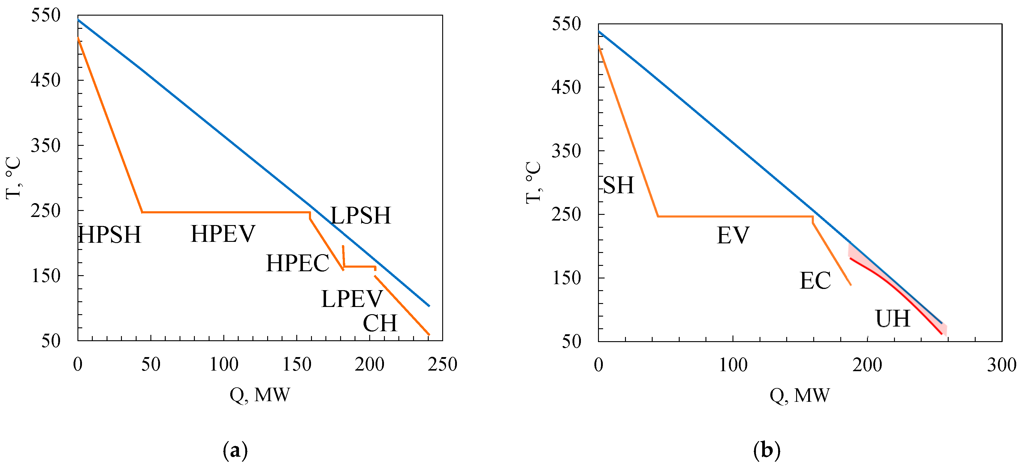
To compare the efficiency of the examined configurations, a CCGT unit based on the GTE-170 with a dual-pressure HRSG was modeled. The results showed a net efficiency of 50.78%, which is 0.79% lower than that of the trinary cycle, but 2% higher than the single-pressure configuration. The superior performance of the trinary cycle is attributed to several factors. First, its enhanced regeneration system in the steam circuit reduces energy losses to the cold sink and partially replaces the condenser heater and economizer, raising the inlet temperature to the utilization cycle. Second, the ORC, using a low-critical-temperature working fluid, recovers residual exhaust heat more effectively than a comparable low-pressure steam circuit. As shown in Figure 3, the T–Q diagram of the trinary cycle features a higher average heat transfer temperature in the low-temperature region and a smaller area between the gas cooling and fluid heating curves, indicating better thermal integration while maintaining the required 10 °C minimum temperature difference.
Thus, the use of cycles on a low-boiling coolant can become one of the possible ways to increase the thermal efficiency of combined-cycle power units. At the same time, fuel afterburning in the exhaust-gas environment can significantly affect the energy efficiency indicators, which requires additional thermodynamic analysis.

3.2. Influence of the Degree of Afterburning on the Parameters of Binary and Trinary Installations

To assess the feasibility of using afterburning chambers in circuits with reheating and an additional circuit on a low-boiling coolant, a preliminary analysis of binary and trinary CCPP based on GTE-170 with a single-circuit HRSG was performed. Additional combustion of fuel in the environment of exhaust gases before the heating surfaces of the waste heat boiler increases the temperature of the working fluid, due to which it becomes possible, on the one hand, to increase the steam capacity of the HRSG, and on the other hand, to raise the initial parameters of steam before the steam turbine. This will directly affect the structure of electric power generation at the CCPP, as well as the level of energy efficiency.
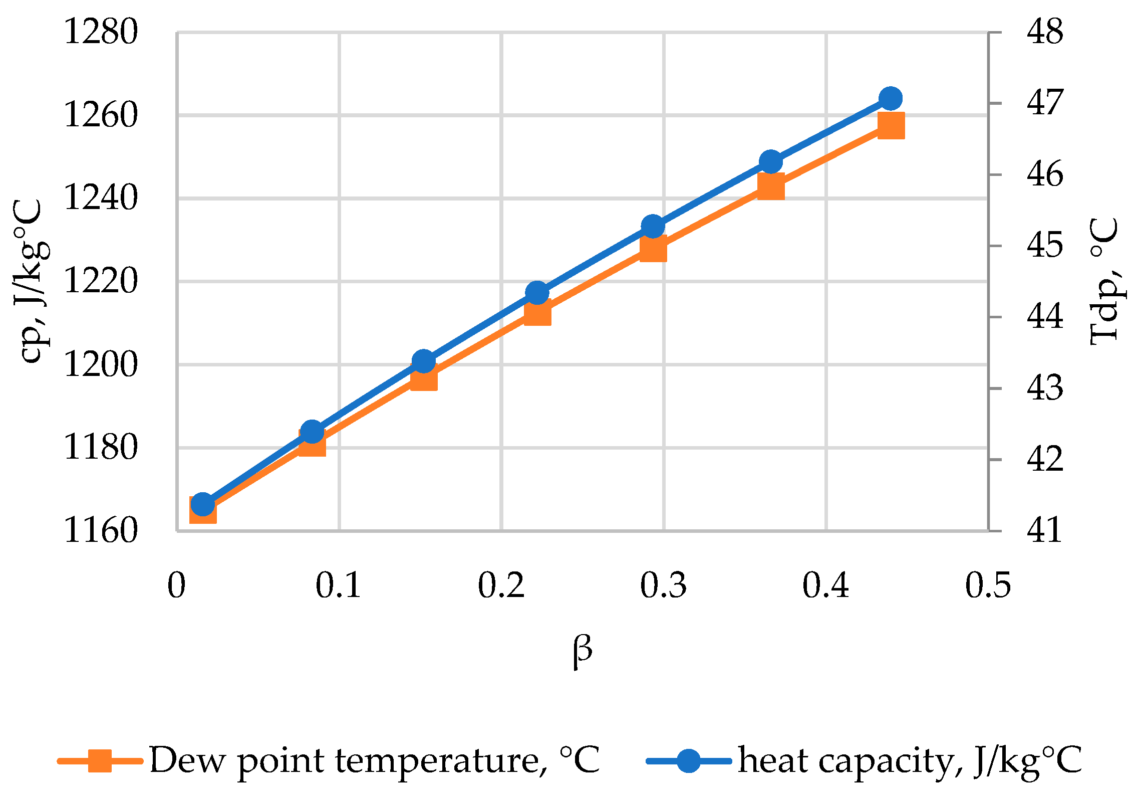
Supplementary firing in the exhaust-gas stream not only raises the gas temperature upstream of the heat-recovery steam generator (HRSG) but also alters the gas properties. Figure 4 shows how the exhaust-gas specific heat and dew-point temperature vary with the degree of supplementary firing. As seen, the specific heat increases due to the higher moisture content in the combustion products, which will affect CCPP performance indicators. At the same time, the dew-point temperature rises, increasing the risk of heat-transfer surface corrosion. However, given the high nitrogen content in the gases (caused by the large excess air in the gas-turbine combustor), condensate formation can be avoided if the heat-exchanger tubes’ wall temperature does not fall below 50–60 °C.
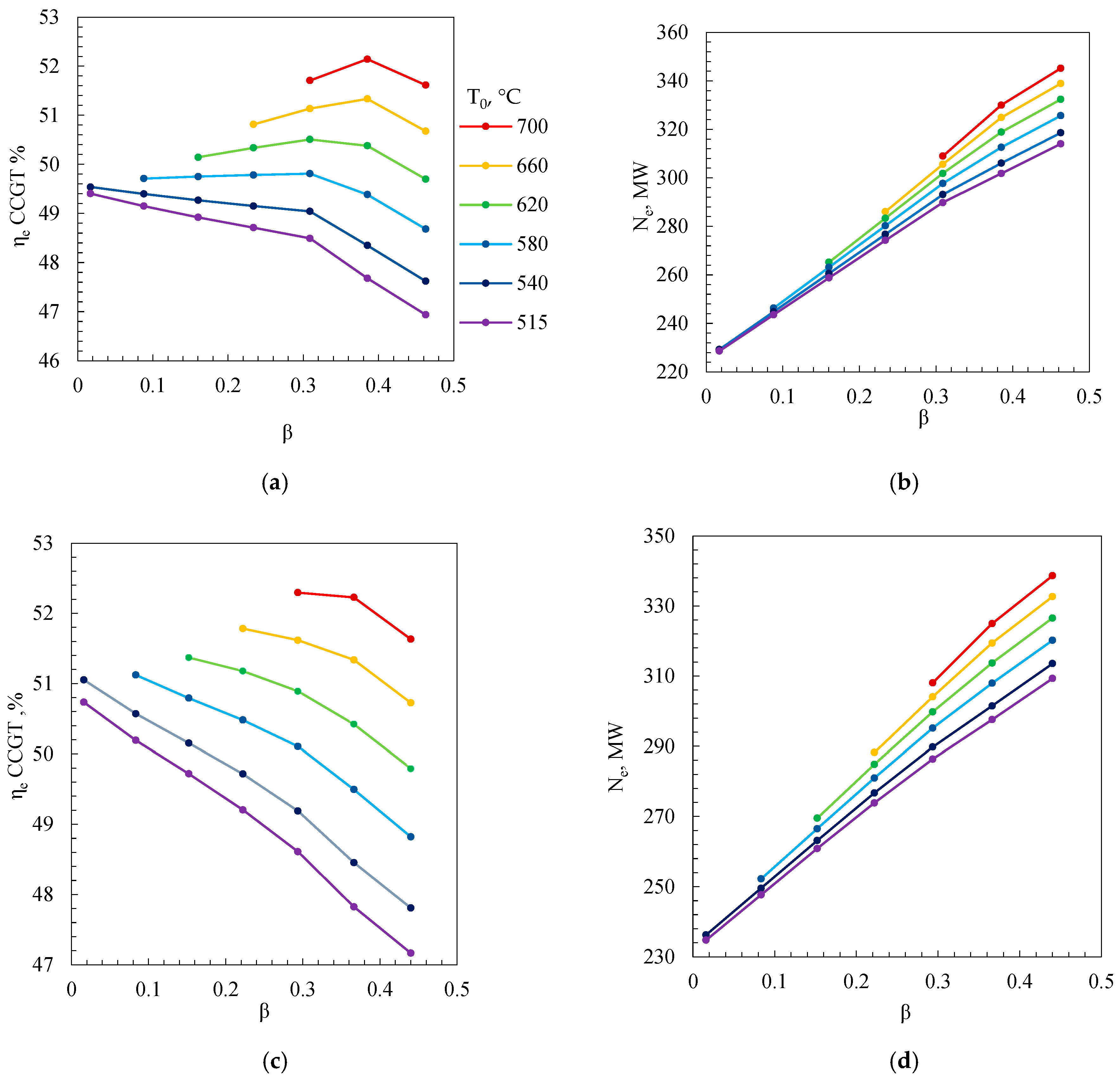
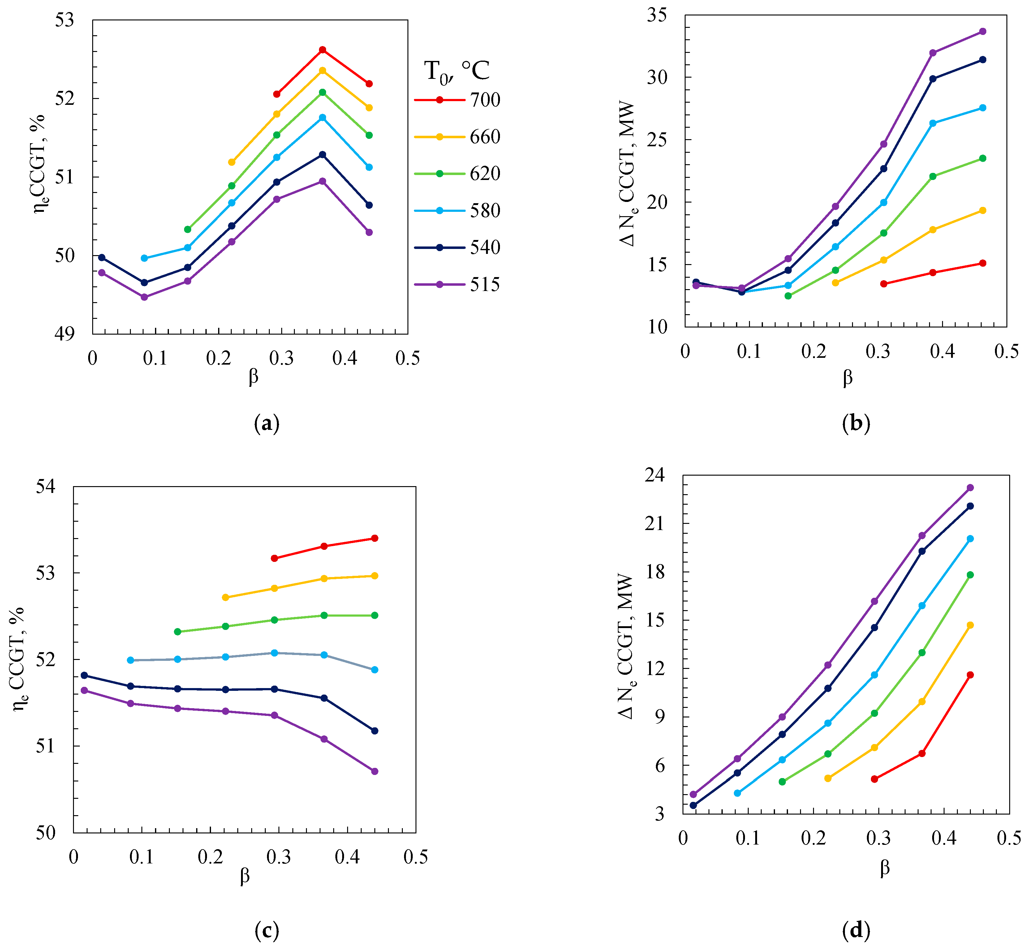
Figure 5 illustrates how the efficiency and power of a CCGT unit with a superheater vary with the degree of afterburning (β) and live steam temperature (T0). For a single-pressure CCGT at T0 = 515 °C, increasing β by 0.1 in the range of [0; 0.3] reduces the efficiency by 0.25%, and up to 0.81% at β = 0.3, where a noticeable inflection appears (Figure 5a). At a higher T0 (≥580 °C), enabled by fuel afterburning before the superheater, increasing β improves efficiency, with a more pronounced effect at a higher T0. This is because, at a lower T0, steam turbine efficiency is limited, and afterburning disproportionately increases low-efficiency power output, making combustion in the GTU more favorable. In contrast, for dual-pressure CCGTs, efficiency decreases across all T0 values, with a sharper decline beyond β = 0.3. For example, at T0 = 515 °C, efficiency drops by 0.58% in [0; 0.3] and by 0.8% beyond (Figure 5c). This negative effect results from energy redistribution toward the low-pressure circuit, reducing overall efficiency. The breakpoint at β = 0.3 is due to the need to increase the temperature head in the evaporative sections, to ensure at least 80 °C exhaust-gas cooling. Despite efficiency losses, the power output rises with β in both configurations, driven by increased steam generation, although the growth rate slows beyond the breakpoint.
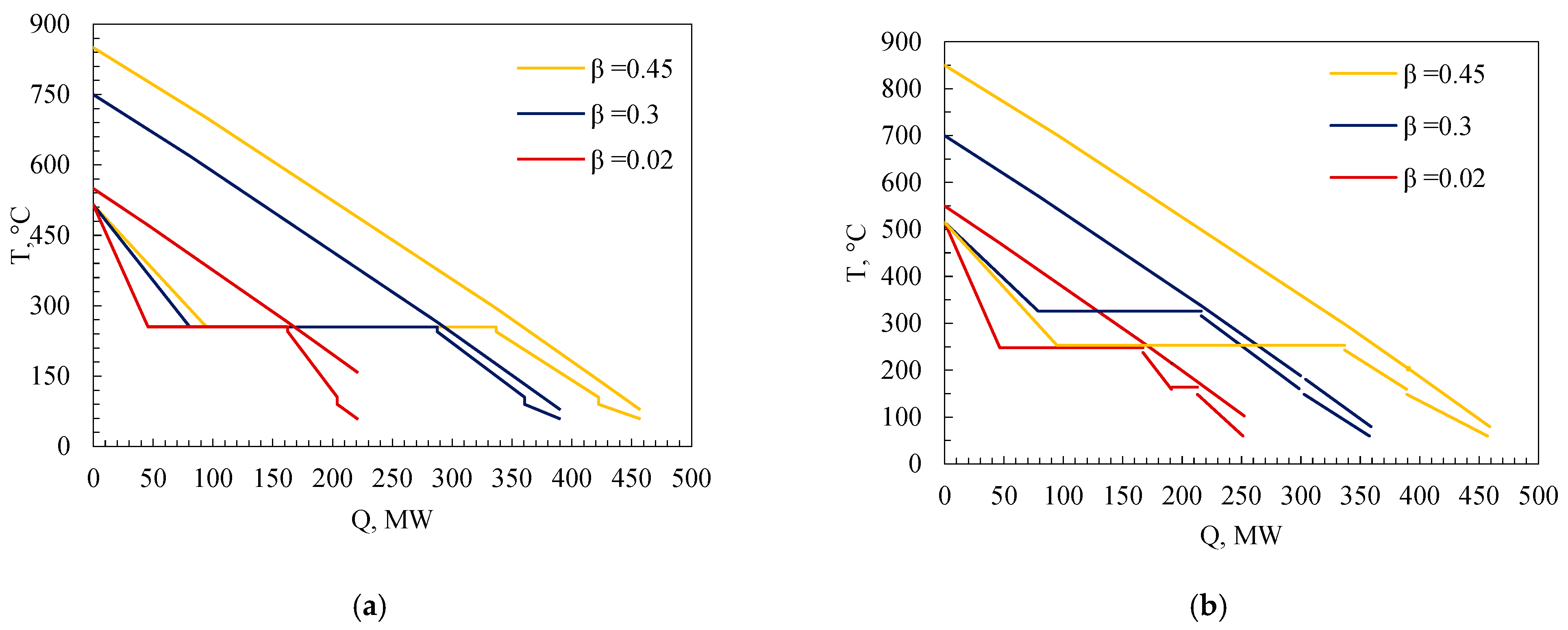
The nonlinear relationship between the CCGT capacity and efficiency versus afterburning degree arises because, at a fixed T0, increasing the gas temperature before the superheater raises steam capacity in the waste heat boiler, allowing deeper cooling of exhaust gases in the economizer and convective heating surfaces (Figure 6a). At a critical afterburning degree βcr, the exhaust-gas temperature reaches 80 °C (with a 20 °C difference at the cold end of the convective heater), and the economizer operates under a near-constant temperature difference. To prevent low-temperature corrosion of heating surfaces with a further β increase, the temperature difference at the pinch point (cold end of the evaporator) must increase, lowering STU thermal efficiency by shifting the average heat supply temperature downward. In dual-pressure CCGTs, this increase in pinch-point temperature difference for both high- and low-pressure evaporators reduces efficiency by decreasing the steam fraction in the more efficient high-pressure circuit (Figure 6b).
Based on the results of multi-series optimization calculations, the dependences of the net efficiency of a trinary cycle on the degree of afterburning at different temperatures of live steam were obtained (Figure 7). It was found that the efficiency of such a cycle decreases with an increase in the degree of afterburning in the entire considered range of β. When comparing the efficiency of binary and trinary cycles with afterburning chambers, it should be noted that the level of net efficiency of trinary units is higher than that of a combined-cycle plant with a waste heat boiler at the same pressure in the entire considered range of β; however, at the breakpoint of the efficiency of a single-circuit combined-cycle plant, the efficiencies of both cycles are closest to each other.

3.3. Effect of Reheater of Steam on Binary and Trinary Combined-Cycle Plants with Afterburning Chambers

Reheating (RH) of steam is one of the simplest and most effective ways to improve the energy efficiency of steam power cycles. In combined-cycle plants with low gas turbine exhaust temperatures, fuel afterburning enables the implementation of RH schemes. Figure 8 shows the net efficiency of CCGT units with single- and dual-pressure HRSGs and RH, as a function of the afterburning ratio β, along with the power increase achieved by switching to RH. For both boiler types, the parallel addition of an RH yields a positive effect across the entire β range. However, the efficiency trend is nonlinear: at live steam temperatures ≤ 540 °C, increasing β initially reduces efficiency, but beyond β ≈ 0.1, it begins to rise, reaching a maximum at β ≈ 0.37. Further increase causes a sharp drop due to the required temperature difference at the pinch point. In dual-pressure systems, rising β allows a reduced pinch temperature in the high-pressure circuit, enhancing efficiency, while the low-pressure circuit still requires an increased temperature difference due to exhaust-gas constraints (Figure 8c).
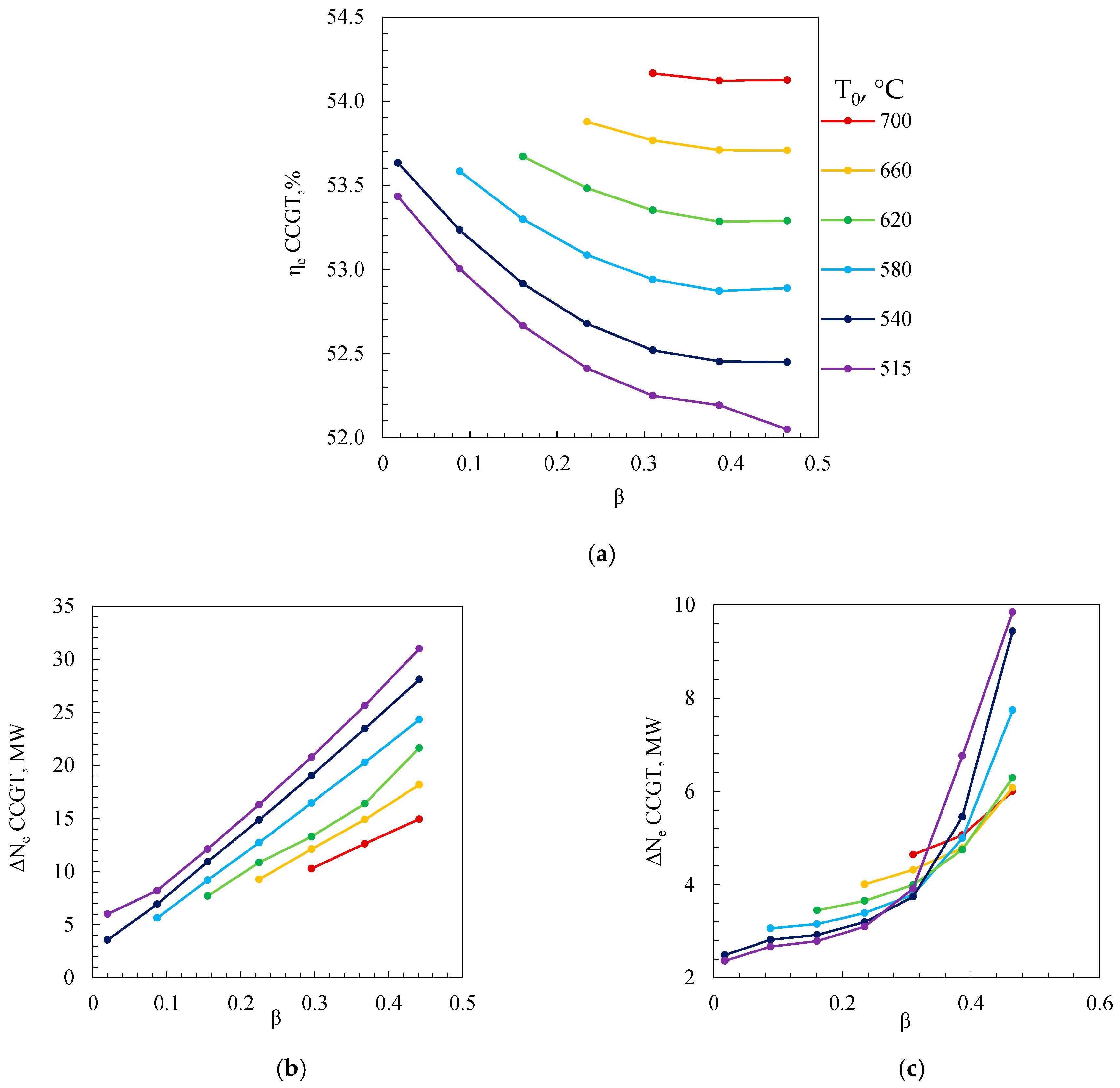
Reheating makes it possible to significantly increase the initial pressure in the cycle while ensuring a sufficient degree of steam dryness at the last stages of the LPT, which has a positive effect on the final efficiency level. In a trinary cycle, the introduction of a low-boiling heat carrier allows for increasing the efficiency by an average of 2.3%, and the increase in the capacity of the combined-cycle plant is determined by both the increase in the coolant flow rate in the steam section and in the refrigerant section (Figure 9a). Figure 9b shows the dependences of the increase in the plant capacity on the introduction of reheating into the cycle. In this case, the transition from binary power plants with a double-circuit waste heat boiler and a low-boiling heat carrier to trinary power plants with a single-circuit waste heat boiler and a low-boiling heat carrier leads to an increase in the power of the power plant. The most significant effect is observed at low T0 values. This indicates the most efficient use of gas heat in a trinary power plant due to the circuit on the low-boiling heat carrier (Figure 9c).
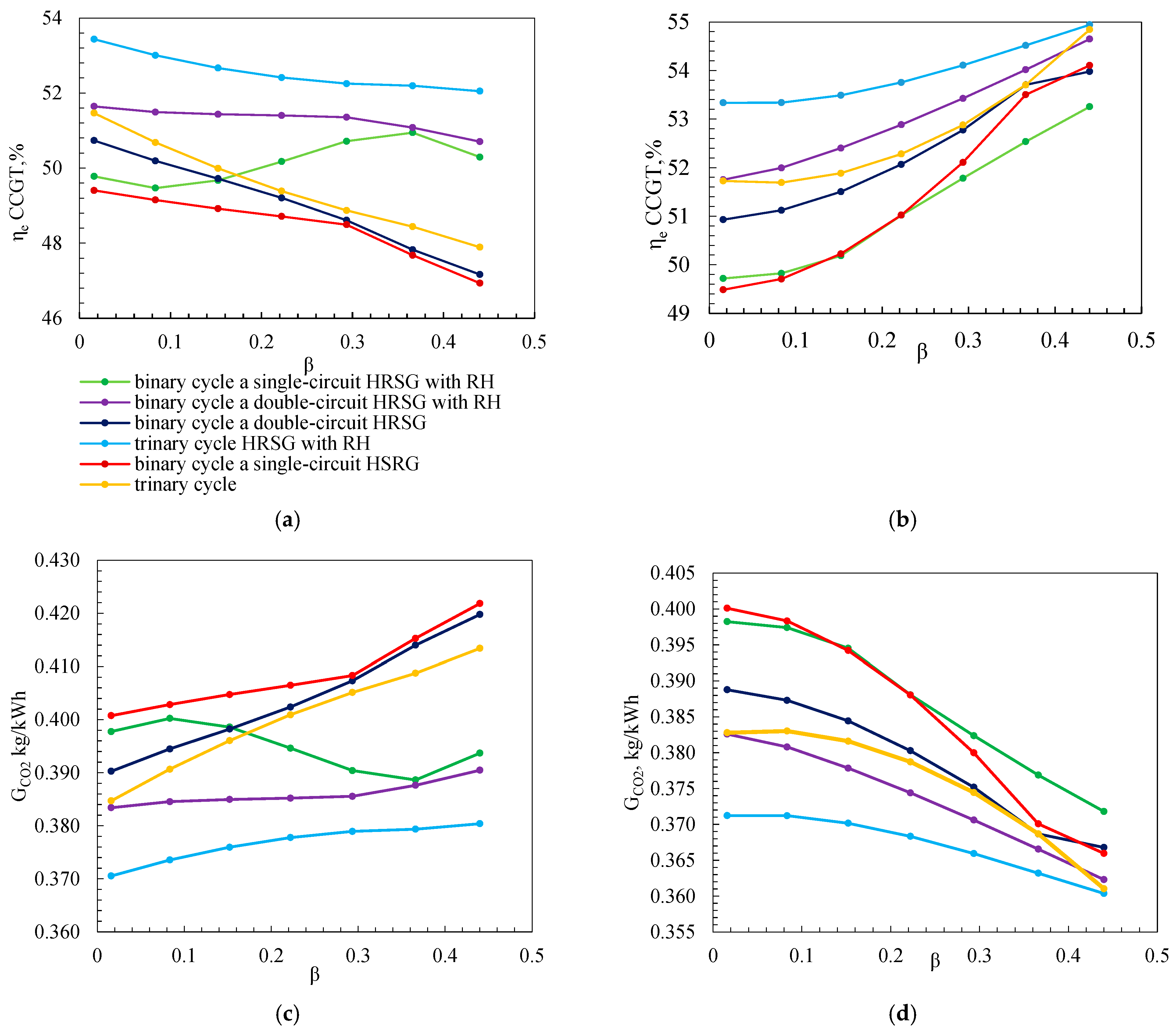
Comparison of all previously considered cycles allows us to draw a conclusion about the feasibility of using circuit solutions. From the graph in Figure 10a, it is evident that at zero fuel consumption for the afterburner, the lowest net efficiency is achieved using a conventional cycle with a single-circuit waste heat boiler, the cycle with RH has a 0.37% higher efficiency, the trinary cycle has a 2.1% higher efficiency, and the trinary with RH has a 4% higher efficiency. In turn, the net efficiency of the trinary power plant with RH is higher than that of the double circuit with RH under the same conditions, at 1.9% higher. With an increase in the degree of afterburning, the efficiency of the binary cycle with reheat begins to exceed the efficiency of the trinary without afterburning, and in turn, the net efficiency of the trinary cycle with reheat is the highest among the considered cycles in the entire range of β.
In the case where the fixed value is not the live steam temperature, but the temperature difference in the reheater, the effect of afterburning becomes more pronounced. Figure 10b shows that due to the increase in the average integral temperature of heat supply to the cycle, the net efficiency of the CCGT increases in the entire range of β. Thus, with a fixed temperature difference in the superheater, an increase in the degree of afterburning by 0.1 leads to an increase in the net efficiency: for a binary cycle based on a single-circuit waste heat boiler, by 0.22%; in a binary cycle with RH, by 0.75%; in a trinary cycle, by 0.24%; and by 0.26% in the case of adding a reheater. The net efficiency of the same trinary power plant with RH is higher than that of the other considered variants of thermal circuits of power plants in the entire range of changes in the degree of afterburning.
The use of supplementary combustion and the organic Rankine cycle make it possible to reduce carbon dioxide emissions in combined-cycle power plants. Compared to a single-pressure combined cycle, the ORC-integrated configuration reduces specific CO2 emissions by more than 7.5%, while supplementary fuel combustion with an increased steam inlet temperature results in a reduction of up to 10% (Figure 10c,d).
Table 6 provides a summary of the considered methods for improving the efficiency of combined-cycle power plants.

4. Conclusions

The development of electricity generation technology at combined-cycle power units in the context of restrictions on the gas turbine market through the development of new circuit solutions can contribute to achieving the goals of resource conservation and energy efficiency in the fuel and energy complex.
Based on the results of studies of various CCPP schemes with GTE-170, the following was established:
  • For a combined-cycle power plant based on the GTE-170, the transition from a binary cycle with a double-circuit waste heat boiler to a trinary cycle can lead to an increase in net efficiency by 0.79%. It has been established that in trinary power plants with a single-circuit waste heat boiler, fuel afterburning leads, on the one hand, to an increase in the capacity of the steam and refrigerant cycles, and on the other hand, to a drop in net efficiency over the entire range of afterburning degrees.
  • Due to the increase in the parameters of gases in front of the waste heat boiler surfaces, it becomes possible to implement schemes with reheating of the steam exhausted in the HPT. Moreover, with the introduction of RH, it becomes possible to increase the optimal initial pressure in the STU cycle to 15 MPa against 4–5 MPa in units without RH. This becomes possible because the final degree of dryness depends on the value of the RH pressure. With the transition to cycles with RH of steam, the increase in the efficiency of the binary cycle is on average 0.4–3% and the trinary cycle 2–4% in the range of the degree of afterburning up to 0.5 at T0 = 515 °C. Comparison of the efficiency of the schemes allows us to conclude that the trinary cycle with RH has a greater efficiency, in comparison with the binary cycle based on the HRSG at one pressure without RH.
  • At a fixed temperature head in the reheater, an increase in the degree of afterburning by 0.1 leads to an increase in the net efficiency: for a binary cycle based on a single-circuit waste heat boiler, by 0.22%; in a binary cycle with RH, by 0.75%; in a ternary cycle, by 0.24%; and by 0.26% in the case of adding RH. At the same time, with an increase in the degree of afterburning, the efficiency of a two-circuit CCGT with reheating approaches the indicators of a trinary and single-circuit CCGT with an RH.
  • The use of supplementary combustion and the organic Rankine cycle makes it possible to reduce carbon dioxide emissions in combined-cycle power plants. Compared to a single-pressure combined cycle, the ORC-integrated configuration reduces specific CO2 emissions by more than 7.5%, while supplementary fuel combustion with an increased steam inlet temperature results in a reduction of up to 10%.
Thus, the transition from binary to trinary cycles enables an increase in energy efficiency. However, it should be noted that the feasibility of developing promising power plants based on the trinary cycle will largely depend on the financial and economic indicators of construction projects, which must be evaluated for specific scenarios. Therefore, tasks related to the development of new equipment operating with low-boiling-point working fluids, as well as models for assessing the costs of trinary power plants, remain highly relevant.

Author Contributions

Conceptualization, V.K.; methodology, V.K.; software, R.Z.; validation, R.Z., A.M.; formal analysis, A.M.; investigation, I.M.; resources, A.M.; data curation, R.Z.; writing—original draft preparation, I.M.; writing—review and editing, V.K.; visualization, I.M.; supervision, A.R.; project administration, A.R.; funding acquisition, A.R. All authors have read and agreed to the published version of the manuscript.

Funding

This study conducted by the Moscow Power Engineering Institute was financially supported by the Ministry of Science and Higher Education of the Russian Federation (project no. FSWF-2023-0014, contract no. 075-03-2023-383, 18 January 2023).

Data Availability Statement

The original contributions presented in this study are included in the article. Further inquiries can be directed to the corresponding author.

Conflicts of Interest

The authors declare no conflicts of interest.

Abbreviations

The following abbreviations are used in this manuscript:
SPPSteam Power Plant
GTUGas Turbine Unit
ORCOrganic Rankine Cycle
HRSGHeat Recovery Steam Generator
STUSteam Turbine Unit
CCGTCombined-Cycle Gas Turbine
SHSuperheater
GEGeneral Electric
ACAir Compressor
GTGas Turbine
CCCombustion Chamber
EGElectric Generator
EVEvaporator
ECEconomizer
CGHCondensate Gas Heater
RPRecirculation Pump
FPFeed Pump
CPCondenser Pump
DDeaerator
CCondenser
HPTHigh-Pressure Turbine
LPTLow-Pressure Turbine
UCUtilization Cycle
HPHHigh-Pressure Heater
LPHLow-Pressure Heater
RHReheater
HHVHigh Heating Value
LHVLow Heating Value

References

  1. JSC “System Operator of the Unified Energy System”. Report on the Functioning of the Unified Energy System of Russia in 2023. 2024. Available online: https://www.so-ups.ru/functioning/tech-disc/tech-disc2024/tech-disc2024ups/ (accessed on 23 October 2025).
  2. Olkhovsky, G.G. The Most Powerful Power-Generating Gas Turbines (Review). Therm. Eng. 2021, 68, 490–499. [Google Scholar] [CrossRef]
  3. Kindra, V.O.; Komarov, I.I.; Zlyvko, O.V.; Maksimov, I.A.; Ostrovsky, M.A. Thermodynamic Analysis of a Trinary Power Plant. Bulletin of the Russian Academy of Sciences. Energetics 2024, 1, 70–81. [Google Scholar] [CrossRef]
  4. Kindra, V.; Komarov, I.; Zlyvko, O.; Maksimov, I.; Ostrovsky, M. Feasibility Study of Scheme and Regenerator Parameters for Trinary Power Cycles. Energies 2023, 16, 3886. [Google Scholar] [CrossRef]
  5. Wieland, C.; Schifflechner, C.; Dawo, F.; Astolfi, M. The Organic Rankine Cycle Power Systems Market: Recent Developments and Future Perspectives. Appl. Therm. Eng. 2023, 224, 119980. [Google Scholar] [CrossRef]
  6. Chong, Q. On Geothermal Heat Extraction from the Basal Cambrian Sandstone Unit in Central Alberta, Canada. 2021. Available online: https://ucalgary.scholaris.ca/items/ec29c6ce-ee52-40c3-b36e-810421212b5b (accessed on 11 June 2024).
  7. Bălănescu, D.T.; Homutescu, V.M. Performance Analysis of a Gas Turbine Combined Cycle Power Plant with Waste Heat Recovery in Organic Rankine Cycle. Procedia Manuf. 2019, 32, 520–528. [Google Scholar] [CrossRef]
  8. Reshaeel, M. Multiparametric Optimization of a Reheated Organic Rankine Cycle for Waste Heat Recovery Based Repowering of a Degraded Combined Cycle Gas Turbine Power Plant. Energy Convers. Manag. 2022, 254, 115237. [Google Scholar] [CrossRef]
  9. Krempus, D.; Bahamonde, S.; van der Stelt, T.P.; Klink, W.; Colonna, P.; De Servi, C.M. On Mixtures as Working Fluids of Air-Cooled ORC Bottoming Power Plants of Gas Turbines. Appl. Therm. Eng. 2024, 236, 121730. [Google Scholar] [CrossRef]
  10. Gogoi, T.K.; Lahon, D.; Nondy, J. Energy, Exergy and Exergoeconomic (3E) Analyses of an Organic Rankine Cycle Integrated Combined Cycle Power Plant. Therm. Sci. Eng. Prog. 2023, 41, 101849. [Google Scholar] [CrossRef]
  11. Komarov, E.M. Methods of Reducing Emissions of Harmful Substances in Combustion Chambers of GTD and GTO. Mech. Eng. Comput. Technol. 2018, 5, 9–29. [Google Scholar] [CrossRef]
  12. Vertkin, M.A.; Kolpakov, S.P.; Mikhailov, V.E. The Upgrading of the Combined-Cycle Cogeneration Plant with Heat-Recovery Steam Generators for Large Cities of the Russian Federation. Therm. Eng. 2021, 68, 110–116. [Google Scholar] [CrossRef]
  13. Borovkov, V.M.; Osmanova, N.M. Determining the maximal capacity of a combined-cycle plant operating with afterburning of fuel in the gas conduit upstream of the heat-recovery boiler. Therm. Eng. 2011, 58, 76–78. [Google Scholar] [CrossRef]
  14. Khomenok, L.A. Development of burners for afterburning chambers of heat-recovery boilers at cogeneration stations equipped with combined-cycle plants. Therm. Eng. 2007, 54, 685–691. [Google Scholar] [CrossRef]
  15. Arakelyan, E.K.; Korshikova, A.A.; Khurshudyan, S.R. The Effectiveness of Using an Additional Low-Pressure Combustion Chamber in the Operation of a PGU-450 Power Unit at Reduced Loads. Bull. Mosc. Power Eng. Inst. 2013, 3, 32–37. [Google Scholar]
  16. Tarasevich, L.; Tuzankin, A. Influence of Heating PSU–KES Scheme Parameters with Additional Fuel Combustion on Changes in Plant Heat Efficiency. Energ. Proc. CIS High. Educ. Inst. Power Eng. Assoc. 2013, 6, 64–71. [Google Scholar]
  17. Yakovlev, B.V.; Grinchuk, A. Optimization of Initial Parameters and the Degree of Fuel Re-Combustion in Combined-Cycle Boilers with One and Two Steam Pressures. Energ. Proc. High. Educ. Inst. Energy Assoc. CIS 2007, 6, 69–77. [Google Scholar]
  18. Encabo Cáceres, I.; Mocholí Montañés, R.; Nord, L.O. Flexible Operation of Combined Cycle Gas Turbine Power Plants with Supplementary Firing. J. Power Technol. 2018, 98, 188–197. [Google Scholar]
  19. Abdollahian, A.; Ameri, M. Effect of Supplementary Firing on the Performance of a Combined Cycle Power Plant. Appl. Therm. Eng. 2021, 193, 117049. [Google Scholar] [CrossRef]
  20. Díaz, A.G.; Sanchez, E.; Santaló, J.G.; Gibbins, J.; Lucquiaud, M. On the Integration of Sequential Supplementary Firing in Natural Gas Combined Cycle for CO2-Enhanced Oil Recovery: A Techno-Economic Analysis for Mexico. Energy Procedia 2014, 63, 7558–7567. [Google Scholar] [CrossRef]
  21. Ahmadi, P.; Dincer, I. Thermodynamic Analysis and Thermoeconomic Optimization of a Dual-Pressure Combined Cycle Power Plant with a Supplementary Firing Unit. Energy Convers. Manag. 2011, 52, 2296–2308. [Google Scholar] [CrossRef]
  22. Fernandez, D.A.P.; Foliaco, B.; Padilla, R.V.; Bula, A.; Gonzalez-Quiroga, A. High Ambient Temperature Effects on the Performance of a Gas Turbine-Based Cogeneration System with Supplementary Fire in a Tropical Climate. Case Stud. Therm. Eng. 2021, 26, 101206. [Google Scholar] [CrossRef]
  23. Power Machines. Gas Turbines. Available online: https://power-m.ru/customers/thermal-power/gas-turbines/ (accessed on 9 July 2024).
  24. Kovalevskii, V.P.; Lebedev, A.S.; Sergeev, A.G. Sravnitel’nyi parametričeskii analiz termodinamicheskoj èffektivnosti kondensacionnyh skhem PGU s GTÈ-160 (V94.2). Elektr. Stantsii 2011, 5, 9–20. Available online: https://elibrary.ru/item.asp?id=16399926 (accessed on 24 October 2025).
  25. Trukhnii, A.D. Parogazovye Ustanovki Elektrostantsii: Uchebnik dlia Vuzov; Izdatel’skii Dom MEI: Moscow, Russia, 2017; 675p. [Google Scholar]
Figure 1. Thermal diagrams of binary and trinary cycles with afterburning chambers installed at the inlet of single-circuit waste heat boilers: binary cycle (a); trinary cycle (b); binary cycle with reheat (c); trinary cycle with reheat (d); binary cycle with a double-circuit waste heat boiler (e); binary cycle with a double-circuit waste heat boiler and reheat (f).
Energies 18 05909 g001
Figure 2. Dependences of the trinary cycle parameters on the feedwater temperature: (a) STU parameters, (b) trinary cycle parameters.
Energies 18 05909 g002
Figure 3. TQ diagrams of the heat recovery steam generators: (a) two circuit; (b) trinary circuit. (blue line—flue gas, orange line—water, red line—refrigerant). Shadow area—minimum temperature approach region.
Energies 18 05909 g003
Figure 4. The dependence of the heat capacity of the combustion products and the dew point temperature on the degree of afterburning.
Energies 18 05909 g004
Figure 5. Dependence of the efficiency for a single-circuit CCGT (a) and for a double-circuit CCGT (c), and the net capacity of the CCGT for a single-circuit (b) and for a double-circuit (d) with a compressor on the degree of afterburning and the initial temperature of the steam.
Energies 18 05909 g005
Figure 6. TQ diagram of a single-circuit combined-cycle gas turbine (a) and a double-circuit combined-cycle gas turbine (b) at different degrees of afterburning.
Energies 18 05909 g006
Figure 7. Comparison of the dependences of the net efficiency of a binary single-circuit waste heat boiler (solid line) and a trinary combined-cycle gas turbine with a heat recovery boiler (dash line) on the degree of afterburning and the initial temperature of the steam.
Energies 18 05909 g007
Figure 8. Dependence of the efficiency of a single-circuit CCGT with reheat and compression ratio (a) of a double-circuit CCGT (c) and the increase in power when introducing reheat for a single circuit (b) and double circuit (d) on the degree of afterburning and the initial temperature of the steam.
Energies 18 05909 g008
Figure 9. Efficiency of a trinary cycle with RH (a), power increase from the introduction of RH (b), and power increase when switching from a two-circuit cycle with RH to a trinary cycle with RH (c).
Energies 18 05909 g009
Figure 10. Comparison of the net efficiency and CO2 emissions of various CCGTs: (a,c) at T0 = 515 °C; (b,d) at ΔTSH = 20 °C.
Energies 18 05909 g010
Table 1. Basic constants adopted in circuit modeling.
ParameterValue
GTU
Exhaust temperature, °C538
Exhaust mass flow rate, kg/s509
GTU capacity, MW155.3
Lower heating value of fuel, MJ/kg50.03
Higher heating value of fuel, MJ/kg55.515
STU
Minimum temperature difference in the superheater, °C20
Minimum temperature difference at the cold end of the evaporator, °C10
Deaerator pressure for single-circuit waste heat boiler, MPa0.12
Deaerator pressure for a dual-circuit waste heat boiler, MPa0.6
Pressure losses in turbine extractions, %5
Pressure losses in HRSG, %5
Pressure loss in the turbine valve, %5
Heat loss in the surfaces of the heating system, %0.4
Underheating of water in economizer to saturation temperature, °C10
Isentropic efficiency of pumps, %85
Condensation temperature, °C30
Water temperature after mixing point in CGH, °C60
Maximum steam humidity behind the last stage of the LPT, %10
Efficiency, %99
Efficiency of electric generator/electric drive, %99
ORC
Isentropic efficiency of turbines, %85
Isentropic efficiency of pumps, %80
Isentropic efficiency of turbines, %90
Isentropic efficiency of compressors, %85
Minimum temperature pressure in the waste heat recovery unit, °C10
Temperature of exhaust gases behind the waste heat recovery unit, °C80
Minimum temperature pressure in the recuperator, °C5
Temperature condensation, °C30
ORC coolantR236ea
Pressure loss in the waste heat recovery unit, %5
Relative internal efficiency of refrigerant turbine and pump, %85
Table 2. Input data for the single-pressure CCPP calculation.
ParameterValue
Gas turbine electrical power, MW150.53
Exhaust-gas temperature, °C543.57
Exhaust-gas mass flow rate, kg/s504.06
Fuel mass flow rate, kg/s9.1614
Fuel lower heating value (LHV), MJ/kg49.157
Heat loss factor0.997
Condenser-pump efficiency0.65
Feedwater-pump efficiency0.8
Generator efficiency0.982
Mechanical efficiency0.99
Terminal temperature difference at the superheater steam outlet, °C20
HP drum pressure, MPa4
LP drum pressure, MPa0.4
Pinch-point temperature difference, °C10
Economizer approach to saturation, °C10
Terminal temperature difference at the economizer outlet, °C20
Relative total pressure losses in steam piping and valves, %0.05
Relative pressure losses in the superheater, %0.05
Pressure-loss coefficient in the feedwater-pump piping1.15
Steam quality (dryness fraction) at the drum outlets0.99
Deaerator pressure, MPa0.02
Condensate subcooling at the deaerator inlet, °C5
Condenser pressure, kPa0.0045
Table 3. Verification results for the single-pressure HRSG model.
ParameterModelingFrom [24]Error, %
Steam wetness downstream of the LP cylinder, %9.018.990.222
CCPP efficiency, %49.6649.480.364
Table 4. Input data for validating the dual-pressure HRSG mathematical model.
ParameterValue
Gas turbine electrical power, MW110
Exhaust-gas mass flow rate367.7
Gas temperature upstream of the HRSG517
Gas turbine efficiency, %36
Condenser pressure, kPa5
HP steam pressure at the steam-turbine inlet6.3
LP steam pressure at the steam-turbine inlet0.58
Generator efficiency0.98
Mechanical efficiency0.99
HP superheater temperature difference, °C27
Relative pressure losses in the HP superheater, %0.05
Feedwater approach to saturation before the HP drum, °C7
HP pinch-point temperature difference, °C8
Feedwater approach to saturation in the deaerator, °C7.5
Deaerator pressure, MPa0.55
LP superheater temperature difference, °C23.5
Relative pressure losses in the LP superheater, %0.63
LP pinch-point temperature difference, °C9.2
Table 5. Verification results for the mathematical model of the dual-pressure HRSG.
ParameterModelingFrom [25]Error, %
CCPP capacity, MW105.59106.090.465
CCPP efficiency, %53.2853.40.225
Table 6. Comparison of net-efficiency gains for a binary CCGT with single-pressure HRSG at T0 = 515 °C across alternative schemes.
SchemeIncrease in ηccgt, %Comment
Double-pressure HRSG1.3% (β = 0)Due to deeper flue-gas cooling in the HRSG
Single-pressure HRSG with RH1.5% (β = 0.37)Due to higher steam dryness in the STU and higher turbine inlet pressure
Trinary cycle2% (β = 0)Due to enhanced regeneration in the STU and efficient ORC-based waste-heat recovery
Double-pressure HRSG with RH2.2% (β = 0)Due to deeper flue-gas cooling and higher steam dryness in the STU
Trinary cycle with RH4% (β = 0)Due to enhanced regeneration in the STU with higher steam dryness and efficient ORC-based waste-heat recovery
Disclaimer/Publisher’s Note: The statements, opinions and data contained in all publications are solely those of the individual author(s) and contributor(s) and not of MDPI and/or the editor(s). MDPI and/or the editor(s) disclaim responsibility for any injury to people or property resulting from any ideas, methods, instructions or products referred to in the content.