Abstract
This study investigates the combustion process in a marine spark-ignition engine fueled with an ammonia–hydrogen blend (15% hydrogen by volume) using a passive pre-chamber. A 3D-CFD model, supported by a 1D engine model, was employed to analyze equivalence ratios between 0.7 and 0.9 and pre-chamber nozzle diameters from 7 to 3 mm. Results indicate that combustion is consistently initiated by turbulent jets, but at an equivalence ratio of 0.7, the charge combustion is incomplete. For lean mixtures, reducing nozzle size improves flame propagation, although not sufficiently to ensure stable operation. At an equivalence ratio of 0.8, reducing the nozzle diameter from 7 to 5 mm advances CA50 by about 6 CAD, while further reduction causes minor variations. At richer conditions, nozzle diameter plays a negligible role. Optimal performance was achieved with a 7 mm nozzle at equivalence ratio 0.8, delivering about 43% efficiency and 1.17 MW per cylinder.
1. Introduction
Recently, due to the significant concentrations of CO2 in the atmosphere, the demand for carbon-free fuels for internal combustion engines has surged. Specifically, ammonia [1,2] can be utilized either as a standalone fuel or as a means of transporting energy for hydrogen generation [3]. Conversely, ammonia poses significant risks to human health. Additionally, it can adversely affect the environment, particularly under windy and arid conditions, although its high volatility facilitates atmospheric dilution. Furthermore, the laminar flame speed of ammonia is quite low [4], and its high ignition temperature complicates the combustion process. However, these issues can be addressed by introducing hydrogen [5,6], a strategy that is also applicable to standard fuels. Ongoing research is concentrating on ammonia–hydrogen mixtures, with the current body of literature offering correlations for the estimation of the laminar flame speed [7,8] and ignition delay [9].
Experimental studies indicate that ammonia can serve as a pure fuel in internal combustion engines [10,11], particularly in spark-ignition engines, or it can be blended with conventional fuels such as gasoline or diesel in dual fuel configurations [12,13]. In their research, Lhuillier et al. [14] examined the combustion performance of a spark ignition engine and concluded that ammonia can serve as a fuel in internal combustion engines, though it requires an adjustment of the spark timing relative to conventional fuels. To enhance the combustion of ammonia in internal combustion engines, it may be beneficial to combine it with an alternative carbon-free fuel, such as hydrogen [15,16]. The research conducted by Pyrc et al. [17] focused on a variable compression ratio spark-ignition engine that operated with hydrogen-enriched ammonia in a dual fuel mode. Their results indicated that the specific energy from hydrogen is instrumental in reducing the instability encountered during the ignition phase. Zhang et al. [18] performed a numerical analysis of the combustion characteristics associated with a spark-ignition engine operating on ammonia–hydrogen mixtures, where hydrogen was obtained via exhaust-fuel reforming. Their results demonstrated that the introduction of hydrogen, up to 10% by volume, resulted in elevated cylinder pressure and a shortened combustion duration.
The performance of an engine utilizing ammonia can be significantly improved through hydrogen enrichment, as well as by addressing structural aspects of the engine, including the implementation of a pre-chamber and multiple spark plugs [19,20]. Considering multiple spark plugs, Uddeen et al. [21] performed an experimental analysis of the combustion and flame characteristics in a spark-ignition engine, focusing on a strategy involving multiple sparks. The results outlined in their paper reveal that a single spark plug located centrally in the combustion chamber produced a lower rate of heat release and a diminished pressure peak. In contrast, the application of multiple spark plugs resulted in a higher heat release rate, increased in-cylinder pressure, and a shorter combustion duration. The authors also noted a reduction in cyclic variation due to the elevated pressure within the combustion chamber. Lastly, the flame analysis indicated that the use of multiple spark plugs facilitated faster flame propagation compared to a single spark setup. On the other hand, there are only a few research papers which investigate the effect of a pre-chamber in an ammonia and ammonia–hydrogen blend engine.
In [22], Qiang et al. investigate the combustion and emission properties of TJI ammonia–hydrogen dual-fuel engines by employing both experimental methods and numerical simulations, varying the ammonia volume share and two different hydrogen injections. Their results show that direct hydrogen injection guarantees higher power with respect to port injection; furthermore, an ammonia volume share equal to 10% allows reaching maximum brake thermal efficiency and maximum brake mean effective pressure. Huo et al. [23] examine how the hydrogen energy fraction, equivalence ratio, and ignition timing influence the combustion and emission characteristics of an ammonia–hydrogen mixture when operating under lean combustion conditions in a pre-chamber marine engine. The authors find that when the hydrogen fraction and equivalence ratio in the main chamber are increased, there is a notable rise in combustion pressure, temperature, and heat release rate (HRR). This increase in reactivity causes a reduction in combustion duration, potentially resulting in end gas auto-ignition and knocking due to the mixture’s diminished auto-ignition energy. Since detonation is a phenomenon to avoid, such configurations can be combined with strategies aimed at reducing the risk of knock [24,25].
Indlekofer et al. [26] use LES modeling to analyze the ignition and combustion dynamics of an ammonia primary charge ignited through a hydrogen-powered pre-chamber. The authors have stated that the timing and angle of injection between the liquid sprays and the hydrogen jet flames that emerge from the pre-chamber significantly influence the ignition and combustion processes. In addition, the non-premixed ammonia main charge configuration greatly reduces pollutant generation and extends the operational range to leaner global equivalence ratios, as opposed to the premixed ammonia main charge configuration. Finally, in [27], Zhao et al. conducted a numerical investigation into the combustion characteristics of ammonia engines equipped with a hydrogen-fueled pre-chamber, considering the effects of nozzle design and the reactivity of the pre-chamber, specifically the amount of hydrogen present. The authors indicated that it is preferable to inject hydrogen into the pre-chamber during the compression stroke. They also said that a highly reactive pre-chamber effectively enhances combustion in the main chamber, and achieving the maximum promoting effect requires a multi-hole pre-chamber rather than a single-nozzle design with a dimension equal to 2 mm for each hole. In these conditions, they obtained a reduction in ammonia emissions, but also an increase in NOx emissions.
Due to the limited results available on the topic, this paper proposes an analysis of the combustion process in a marine engine fueled by ammonia–hydrogen mixtures. On the basis of an existing diesel engine, developed for naval applications, the combustion chamber has been designed considering a passive pre-chamber able to allow jet ignition of the air–fuel mixture. Preliminary numerical analyses have been carried out in order to examine the effects of different nozzle sizes and equivalence ratios. Simulations were performed using both one-dimensional and three-dimensional computational fluid dynamics (CFD). Additionally, a preliminary analysis of the pollutants generated by the engine was undertaken in order to identify the engine’s optimal operating conditions.
To the best of the authors’ knowledge, this study is among the first computational investigations of ammonia–hydrogen combustion in a large-bore marine engine equipped with a passive pre-chamber. In contrast to previous research, mainly focused on active pre-chambers or non-marine configurations, this work combines one-dimensional and three-dimensional models to determine the effect of the equivalence ratio and the nozzle diameter on combustion characteristics, engine performance, and emissions under actual operating conditions. It is worth noting that the proposed analysis is not intended to accurately estimate the engine performance but to verify the feasibility of the proposed solution. Furthermore, the suggested methodology may prove beneficial for future numerical studies related to this type of engine, where conducting experimental analyses could be exceedingly intricate and costly.
2. Materials and Methods
2.1. Engine Geometry
The engine under study (Table 1) has been designed based on the main geometric parameters of the well-known WR6L46 engine from Wärtsilä (Helsinki, Finland). This is a four-stroke, medium-speed (300–1000 rpm) marine diesel engine with a flat head cylinder and four valves per cylinder [28]. The geometrical compression ratio has been set equal to 12.5, like in [29], where the same engine was considered for dual fuel operation. The engine presents a piston bowl capable of receiving fuel jets from the pre-chamber. The latter is connected to the main chamber through the pre-chamber nozzle. Figure 1 presents the analyzed domain, which corresponds to 1/6 of the whole engine geometry. The proposed pre-chamber has been designed based on the one presented in [23] for a similar engine. It is located on the cylinder head, in line with the cylinder axis (Figure 1), and it features 6 nozzles, 20 degrees tilted to the cylinder axis. Its volume is 0.8% of the combustion chamber volume, while, for the nozzle diameter, three different values, ranging from 3 mm to 7 mm, have been considered. The pre-chamber design allows both active mode and passive mode operation. In this paper, only the last one has been considered with a single spark plug, flat-mounted on the pre-chamber ceiling along the cylinder axis.

Table 1.
Main engine characteristics. BTDC denotes “before top dead center”. ATDC denotes “after top dead center”.
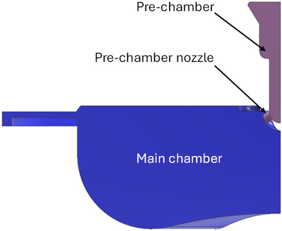
Figure 1.
Engine geometry with details of the pre-chamber and main chamber.
The intake port design has been considered not able to induce organized charge motions to the charge entering the cylinder. So, an almost quiescent charge could be assumed at the intake valve closing. This allows analyzing the combustion progress in a satisfactory way by considering only the compression and expansion strokes without modeling the charge exchange processes.
2.2. Case Study
In order to evaluate the potential of the engine fueled with an ammonia–hydrogen mixture, the cases shown in Table 2 have been analyzed. In particular, the influence of the nozzle size and the equivalence ratio (ϕ) of the air–fuel mixture has been evaluated. The engine operating point has been set considering a given engine speed and fixed conditions in the intake manifold. The engine speed is equal to 500 rpm, which is a typical cruise velocity for this kind of engine, as also for the boost pressure considered at full load conditions.
Table 2.
Case studies.
For the spark advance, a value, utilized in the literature studies conducted under similar conditions (8 CAD), has been chosen [23].
2.3. Numerical Approach
Analyses have been performed by means of 3D numerical calculations starting at the intake valve closing (IVC) and ending at the exhaust valve opening (EVO). The 3D numerical approach developed and validated in [30] has been used to assess both flow and combustion behavior inside the engine combustion chamber.
Briefly, the balance equations governing the unsteady, turbulent, and chemically reacting turbulent flow inside the chamber are solved by means of the AVL Fire code [31] by using a RANS approach [32,33]. The k-z-f approach has been coupled to the Reynolds-averaged transport equations to model the turbulent effects [34]. It has been chosen because of its capability to accurately resolve flow characteristics in proximity to the wall, in accordance with a hybrid wall treatment. The heat transfer through the walls has been represented using a conventional wall function. The oxidation process of the ammonia-hydrogen fuel mixtures has been simulated by incorporating the chemical kinetics mechanism proposed by Stagni et al. [35] into the three-dimensional model. A summary of the mechanism utilized is provided in Table 3. The model considers ammonia decomposition, hydrogen abstractions, the dissociation of the HNO intermediate, and the generation of NO resulting from both the dissociation of NH3 and the oxidation of nitrogen present in the air. The involved species are described according to the ideal gas law. In particular, thermodynamic data available in [36] have been used.
Table 3.
Chemical kinetic mechanism details.
Ignition has been successfully reproduced by introducing a given amount of energy into a sphere with a diameter of 3 mm. The positioning of this sphere is aligned with the location of the spark-plug electrodes, and the energy release is modulated in accordance with the literature data.
2.4. Initial and Boundary Conditions
No-slip conditions and constant temperature values based on the literature data for similar engines have been set on the walls.
The charge has been considered initially homogeneous and motionless. The initial turbulent intensity has been set equal to 10% of the mean piston speed, while the initial integral length scale has been assumed equal to 10% of the diameter of the considered domain.
In both the pre-chamber and the main chamber, temperature, pressure, and charge composition at IVO have been provided by preliminary 1D calculations.
A single-cylinder model (Figure 2) of the investigated engine has been built in the well-known GT-Power environment [37]. The engine layout part between the intake and exhaust manifolds has been reproduced. The pre-chamber is described as a constant volume connected to the main combustion chamber, while the mixture formation is modeled considering the gaseous injection of the NH3/H2 mixture into the cylinder intake duct. Combustion is imposed by means of assumed Wiebe functions.
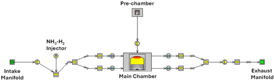
Figure 2.
One-dimensional single cylinder model.
The calculations have been performed considering both the pressure and the temperature of the air present in the intake manifold as constant. Just as an example, Figure 3 shows the mixture composition in both the pre-chamber and the main chamber calculated during the engine cycle. The charge composition is nearly constant in the main chamber during much of the suction and compression strokes, while in the pre-chamber it varies markedly. It is worth noting that at the beginning of the compression stroke, the presence of residues from the previous cycle is much higher in the pre-chamber than in the main chamber.
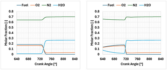
Figure 3.
Mixture compositions in the combustion chamber (main chamber (left), pre-chamber: (right)) according to 1D preliminary calculations. Equivalence ratio equal to 0.8, nozzle size equal to 5 mm.
2.5. Grid Sensitivity
Engine geometry, initial and boundary conditions, allow restricting the analysis to 1/6 of the combustion chamber. Unstructured grids have been generated using hexahedral elements with a fixed dimension that varies from 4 mm to 5 mm.
The mesh sensitivity analysis has been carried out considering a nozzle diameter equal to 7 mm and an equivalence ratio equal to 0.8. Figure 4 presents the calculated pressure curves for the investigated grids. The intermediate and the finest grids show a combustion development very similar to and faster than that of the coarsest grid. Considering the pressure peak, the coarsest grid has a difference of approximately 5% with respect to the intermediate grid, while the latter has a difference of only 1% compared to the finest one. The same trend is shown in Table 4 for the combustion duration; in fact, moving from the coarsest grid to the intermediate one, the variation in the CA 0–10 is about 6%, while evaluating the finest one and the intermediate one, there is only 2%.
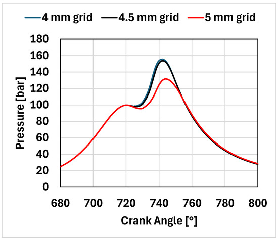
Figure 4.
In-cylinder pressure curves for different engine grid sizes.
Table 4.
Combustion durations for the different mesh investigate.
Finally, for all the considered grids, emissions have been investigated in terms of unburned ammonia and NOx, which are the main pollutants related to the ammonia combustion, as already discussed in [34]. Table 5 presents a whole comparison between the three-engine grids tested. In these cases, the finest and the intermediate grids provide almost identical results, while the coarsest grid presents a large deviation with respect to the other ones.
Table 5.
Emissions for the different engine grid.
At the end, the intermediate grid (Figure 5) has been chosen as the best trade-off between result reliability and calculation speed. This grid presents 134,884 elements at TDC and 478,720 elements at EVO, with a maximum element dimension equal to 4.5 mm. It was chosen in order to reasonably contain the calculation times, allowing, at the same time, to appropriately assess the effects of different equivalence ratios and pre-chamber nozzle diameters on in-cylinder pressure development and emission trends of the analyzed engine.
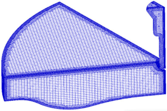
Figure 5.
Engine grid with 4.5 mm element size.
2.6. Model Validation
The proposed approach has already been validated [30,38] on a light-duty SI engine, considering experimental tests with different hydrogen enrichment (up to 15% by volume). The results shown in Figure 6 clearly demonstrate that the proposed model accurately predicts the combustion behavior of the engine operating with various ammonia-hydrogen blends.
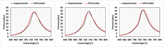
Figure 6.
Model validation considering a light-duty engine [30]. The mixtures investigated were neat ammonia (left), 5% of hydrogen by volume (middle), and 15% of hydrogen by volume (right).
The potential of the numerical approach applied to a large engine equipped with a pre-chamber has also been evaluated, reproducing the results published by Huo et al. [23]. These authors calculated the combustion development under various conditions in an engine fueled with an ammonia–hydrogen mixture, characterized by a displacement of 65.32 L per cylinder, a geometric compression ratio of 11.25. The main combustion chamber featured a piston bowl similar to that of diesel engines, while the pre-chamber, considered as a reference for this study, is active through the injection of a certain quantity of hydrogen. This engine has been discretized with the same approach described in Section 2.5, and the initial and boundary conditions were replicated following the details reported by the authors. Figure 7 shows the pressure and temperature curves calculated for a hydrogen amount equal to 20% by volume and an equivalence ratio in the main chamber equal to 0.6. The proposed model still presents a good agreement with the reference results; there is only a slight overestimation of both the pressure and temperature peaks. This encourages the authors to use it for the calculations reported in this paper.
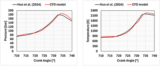
Figure 7.
In-cylinder pressure (left) and temperature (right) curves. Reference data from [23].
3. Results
3.1. Combustion Development
In all the investigated points, the flame initially develops by consuming the whole air–fuel mixture contained within the pre-chamber. The angular duration required to burn 90% of the fuel mass present in the pre-chamber decreases with the enrichment of the mixture, while it is little affected by the nozzle size (Table 6). On average, its value varies from 10° when ϕ = 0.7 to 7° when ϕ = 0.9.
Table 6.
Combustion durations relative to the pre-chamber volume.
During this phase, the trend of the average temperature of the gases in the pre-chamber is very similar for all the investigated cases, and it is not influenced by the nozzle diameter (Figure 8). The maximum value obviously tends to grow as the richness of the mixture increases and reaches a peak just below 2500 K for the richest mixture (Figure 8). On the contrary, the nozzle area influences the pressure developments in the pre-chamber (Figure 9). This leads to different jets within the combustion chamber (Figure 10), with different velocities and turbulence production (Figure 11). In each instance, however, the flow in the nozzle remains subsonic, as shown in Table 7.
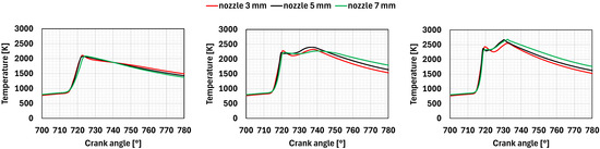
Figure 8.
Pre-chamber volume: mean temperature calculated for different equivalence ratios and nozzle diameters (ϕ = 0.7 (left)), (ϕ = 0.8 (middle)), (ϕ = 0.9 (right)).
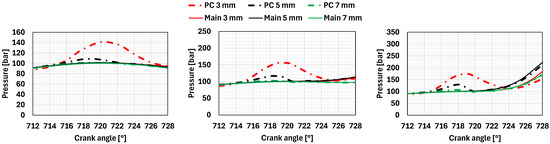
Figure 9.
Comparison of mean pressure in the main and pre-chambers for different equivalence ratios and nozzle diameters. (ϕ = 0.7 (left)), (ϕ = 0.8 (middle)), (ϕ = 0.9 (right)).
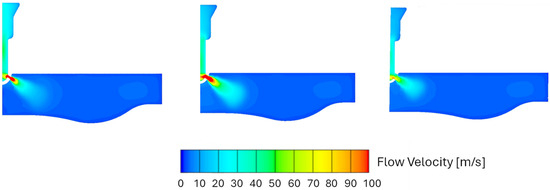
Figure 10.
Velocity magnitude for the case with an equivalence ratio of 0.8 and different nozzle sizes (3 mm (left), 5 mm (middle), 7 mm (right)) at a given crank angle.
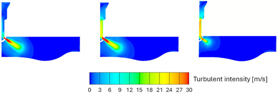
Figure 11.
Turbulent intensity for the case with an equivalence ratio of 0.8 and different nozzle sizes (3 mm (left), 5 mm (middle), 7 mm (right)) at a given crank angle.
Table 7.
Maximum Mach number [-] calculated at the nozzle orifice.
All the jets ignite the mixture within the combustion chamber, as shown in Figure 12, where the O2 consumption has been chosen to define the burned zone boundary, with a threshold value equal to 90%.
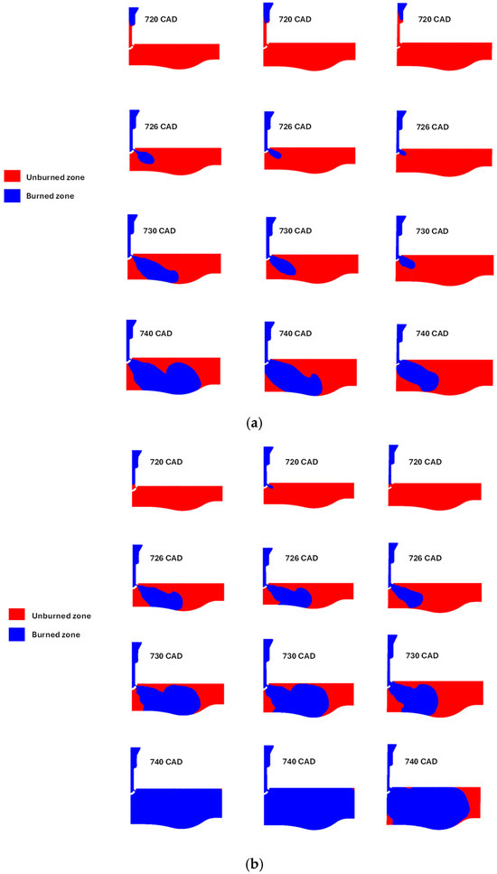
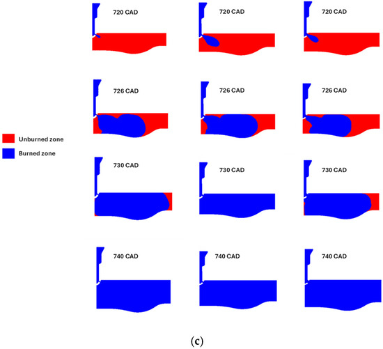
Figure 12.
Burned and unburned zone evolution for an equivalence ratio of 0.7 (a), 0.8 (b), and 0.9 (c). From left to right: nozzle diameters 3, 5, 7 mm.
The influence of the nozzle size on the flame development varies with the considered equivalence ratio. For the leanest mixture, the rate of flame development increases noticeably as the nozzle size decreases. However, results show that this mixture does not support fast enough flame development to complete the combustion process.
Burning a mixture with ϕ = 0.8, the combustion speeds up when the nozzle diameter reduces from 7 mm to 5 mm. A further reduction in the nozzle size yields no additional benefits; actually, the process appears slightly slower during the initial phase. For the richest mixture, the nozzle size has little influence on the flame propagation inside the main chamber. In addition, in this case, slightly faster combustion is achieved with a 5 mm nozzle diameter. Both 3 mm and 5 mm nozzle configurations present similar velocity and turbulent intensity fields at the nozzle outlet at 720 CAD (Figure 10 and Figure 11), but, for the 5 mm case, the faster initial formation of the flame jet leads to a faster flame development within the main chamber. On the contrary, the 7 mm nozzle presents both lower mean velocities and turbulence intensity at the nozzle outlet (Figure 10 and Figure 11), and the initial flame jet development is not fast enough to have an increase in the flame speed within the main chamber.
Figure 13 presents the consequent pressure development in the main chamber, while Table 8 shows the main quantities describing the combustion process in the main chamber. The IMEPH stands for the indicated mean effective pressure, calculated for the engine cycle’s high-pressure part. (i.e., from IVC to EVO). The term CA0-10 refers to the crank angle duration necessary to burn 10% of the fuel mass from the ignition angle, while CA10-90 indicates the crank angle duration required to transition from 10% to 90% of the burned fuel mass. CA50 represents the delay angle in relation to the PMS at which 50% of the fuel has been burned. The engine efficiency is calculated as the ratio of the work delivered by the engine cycle’s high-pressure part to the heat that could be developed from the complete combustion of the fuel.
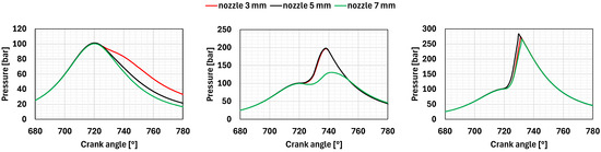
Figure 13.
Mean in-cylinder pressure curves for different equivalence ratios (ϕ = 0.7 (left), ϕ = 0.8 (middle), ϕ = 0.9 (right)), and different nozzle sizes.
Table 8.
Combustion durations and mean indicated pressure calculated for each case.
An equivalence ratio equal to 0.7 does not provide proper combustion. The flame development is too slow, and only the smallest nozzle allows for burning more than 50% of the fuel. The pressure cycle behaves similarly to a motored cycle, and the IMEPH is slightly above zero.
With an equivalence ratio of 0.8, the two smaller nozzles perform very similarly, while the pre-chamber with the largest orifice shows a slower pressure development. In fact, moving from a nozzle diameter equal to 7 mm to a nozzle diameter equal to 5 mm, the combustion duration significantly reduces, while moving from 5 mm to 3 mm, the variation in terms of combustion duration is negligible. In the last two cases, the maximum pressure in the chamber reaches approximately 200 bar, with an IMEPH of around 31.5 bar. On the other hand, for the case with the largest nozzle, the maximum pressure is significantly lower at about 130 bar. However, this configuration still achieves an IMEPH of 29.2 bar with an engine efficiency of 43.8%.
The highest equivalence ratio results in the highest-pressure curves, with the three nozzle geometries producing very similar outcomes. Combustion occurs very quickly, with 90% of the mass burned in less than 20 crank angle degrees. The maximum pressure ranges from 270 bar to 280 bar, and the slope of the pressure curve is quite steep.
3.2. Emissions
The emissions detected in both the calculation domains are consistent with the analyses carried out so far. Table 9 and Table 10 show the NH3 and NOx concentrations calculated in both the main chamber and the pre-chamber at the exhaust valve opening, respectively.
Table 9.
Main chamber emissions. Data refer to wet exhaust gases.
Table 10.
Pre-chamber emissions. Data refer to wet exhaust gases.
In the main chamber, with an equivalence ratio of 0.7, the presence of unburned ammonia indicates largely incomplete combustion. However, especially when the nozzle size decreases, the presence of a flame inside the chamber leads to the formation of NOx due to both the dissociation of NH3 and the activation of the Zeldovich mechanism.
Considering ϕ = 0.8 and ϕ = 0.9, the entire charge is burned, leading to near-zero unburned ammonia concentrations within the main chamber, while the NOx concentration increases. It is worth noting that the concentration of NOx is higher for the cases at ϕ = 0.8 rather than for those at ϕ = 0.9, despite the lower average temperatures calculated in the main chamber. This may be due to the leaner mixture, which, with average temperatures still above 2000 K, makes more oxygen available for the oxidation of nitrogen.
At a given equivalence ratio, results show that cases with similar pressure development are also characterized by almost identical NOx emission values.
The emissions detected in the pre-chamber show minimal unburned ammonia levels, a consequence of almost complete combustion, while the NOx levels are significantly elevated and comparable to those found in the main chamber. This excludes the cases at ϕ = 0.7, where complete combustion occurs only in the pre-chamber.
As an example, Figure 14 presents unburned NH3, NO, and NO2 distributions at EVO considering an equivalence ratio of 0.8 and a 7 mm nozzle. It can be clearly noted that the higher concentrations of NO and NO2 are located in the zone that, according to Figure 12, is last reached by the flame front. As expected, similarly, unburned ammonia is concentrated only in the zone that is not completely reached by the flame.
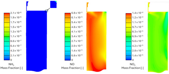
Figure 14.
Unburned NH3, NO, and NO2 emissions for the case with an equivalence ratio of 0.8 and a 7 mm nozzle at EVO.
4. Comparison with the Existing Literature
The results obtained in this study are generally consistent with the trends reported in previous studies on ammonia and ammonia–hydrogen combustion in pre-chamber engines, while exhibiting specific features related to the passive pre-chamber configuration adopted in a large-bore marine engine.
Huo et al. [23] numerically investigated a marine engine equipped with an active pre-chamber fueled by an ammonia–hydrogen mixture. Their analysis showed that the high reactivity within the pre-chamber promotes rapid jet formation and ensures stable combustion across a wide range of lean conditions. In contrast, the present study focuses on a passive pre-chamber configuration, assessing the combustion behavior with different equivalence ratios and nozzle sizes. The results indicate that, without direct fuel injection into the pre-chamber, jet development and flame propagation are slower, and complete combustion is achieved only at moderate lean conditions, around an equivalence ratio of 0.8.
Liu et al. [39] examined an active pre-chamber system fueled with ammonia–hydrogen mixtures in a single-cylinder research engine representative of automotive applications. Their analyses confirmed that direct fuel supply to the pre-chamber substantially extends the lean combustion limit due to enhanced turbulence and radical generation within the jets, phenomena that are inherently less pronounced in passive configurations such as the one investigated in the present study.
Li et al. [40] conducted a combined experimental and numerical study on ammonia–hydrogen mixtures in a constant-volume pre-chamber combustion vessel, aiming to characterize the jet ignition process under engine-relevant conditions. Their results demonstrated that the jet penetration, ignition delay, and flame development are strongly affected by the pre-chamber nozzle diameter and orientation, as well as by the equivalence ratio. Although the setup considers a constant volume vessel, these findings confirm the relevance of nozzle-diameter optimization for stable operation of low-reactivity ammonia–hydrogen mixtures, in agreement with the present numerical results for the marine-scale engine configuration.
Qiang et al. [41] performed experimental tests on a single-cylinder spark-ignition engine fueled with ammonia–hydrogen blends and equipped with a passive pre-chamber ignition system. The study analyzed the effects of global excess–air ratio and spark timing on combustion stability and efficiency. Results revealed that stable operation is achievable only within a narrow lean range, with complete combustion occurring near stoichiometric conditions. These observations are consistent with the present numerical findings, which indicate similar constraints for achieving full charge burn in passive pre-chamber configurations under lean operation in the analyzed large-bore marine engine.
Overall, the outcomes of this work complement previous investigations by providing useful insight into how equivalence ratio and nozzle size jointly affect flame development and pollutant emissions in a passive pre-chamber marine engine fed with ammonia–hydrogen mixtures, an aspect scarcely addressed in the existing literature, which has mainly focused on active pre-chamber or small-scale laboratory applications.
5. Conclusions
A preliminary study that investigates the characteristics of the combustion process in an ammonia/hydrogen marine engine using a passive pre-chamber is presented. Analyses have been carried out varying both the equivalence ratio (from 0.7 to 0.9) and the nozzle diameter of the pre-chamber (from 7 to 3 mm). The main engine operative parameters (such as engine speed, spark advance, and engine inlet pressure) have been kept constant. Analyses have been performed using a computational fluid dynamics (CFD) model, with boundary and initial parameters derived from a simplified one-dimensional model of the engine.
The main results can be summarized as follows:
- For each equivalence ratio, the turbulent jets ignite the charge within the main chamber, but an equivalence ratio below 0.8 does not allow the development of combustion rapid enough to completely burn the charge. To guarantee a proper combustion process with leaner mixtures, further improvements, like a higher hydrogen enrichment or the use of an active pre-chamber, can be employed.
- The influence of the nozzle size depends on the air–fuel mixture. For the leanest analyzed mixture, a smaller nozzle diameter tends to improve combustion, but not enough to guarantee a proper combustion process. For the equivalence ratio 0.8, the transition from 7 mm to 5 mm diameter is significant (the CA50 advances of about 6 CAD, for example), while the transition from 5 to 3 mm has little impact (the CA50 advances of 0.6 CAD). For the richest mixture, the impact is negligible.
- The engine geometry characterized by a nozzle diameter equal to 7 mm with an equivalence ratio equal to 0.8 is the only one that provides a proper pressure development process. In this operating point, calculations predict a good engine efficiency (about 43%, considering only the high-pressure cycle) delivering a power equal to 1.17 MW per cylinder when it runs at 500 rpm.
- Complete combustion can lead to significant NOx emissions, which are poorly affected by the nozzle size. Cases with an equivalent ratio equal to 0.8 show more NOx than those with an equivalent ratio equal to 0.9.
This paper assesses the possibility of substituting conventional fuels with carbon-free fuels on marine engines, presenting qualitative results, which show that ammonia–hydrogen blends could be used in a modified marine engine equipped with a passive pre-chamber. However, the engine is not able to guarantee a proper operation with the leanest mixture analyzed. This limit could be overtaken considering a higher hydrogen enrichment in the fuel blend or by using an active pre-chamber. Furthermore, future analyses can also assess the possibility of using lower hydrogen amounts in the fuel mixture for the highest equivalence ratio, and performance and emissions of the analyzed engine at low load operation.
Author Contributions
Conceptualization, E.G. and D.L.; methodology, E.G. and D.L.; software, G.D. (Gabriele D’Antuono) and G.D. (Gianpaolo D’Andrea); validation, G.D. (Gabriele D’Antuono) and G.D. (Gianpaolo D’Andrea); formal analysis, G.D. (Gabriele D’Antuono), E.G. and D.L.; investigation, G.D. (Gabriele D’Antuono); data curation, G.D. (Gabriele D’Antuono), G.D. (Gianpaolo D’Andrea), and E.G.; writing—original draft preparation, G.D. (Gabriele D’Antuono), E.G. and D.L.; writing—review and editing, E.G., D.L. and G.F.; supervision, E.G. and G.F. All authors have read and agreed to the published version of the manuscript.
Funding
This research has been supported by the Italian Government (LYRICA, PRIN project 2022, code 2022M7BHN7).
Data Availability Statement
The raw data supporting the conclusions of this article will be made available by the authors on request.
Conflicts of Interest
The authors declare no conflicts of interest.
References
- Tornatore, C.; Marchitto, L.; Sabia, P.; de Joannon, M. Ammonia as Green Fuel in Internal Combustion Engines: State-of-the-Art and Future Perspectives. Front. Mech. Eng. 2022, 8, 944201. [Google Scholar] [CrossRef]
- Valera-Medina, A.; Xiao, H.; Owen-Jones, M.; David, W.; Bowen, P. Ammonia for power. Prog. Energy Combust. Sci. 2018, 69, 63–102. [Google Scholar] [CrossRef]
- Kojima, Y.; Yamaguchi, M. Ammonia as a hydrogen energy carrier. Int. J. Hydrogen Energy 2022, 47, 22832–22839. [Google Scholar] [CrossRef]
- Yan, Y.; Shang, T.; Li, L.; Liu, Z.; Liu, J. Assessing Hydrogen–Ammonia Ratios to Achieve Rapid Kernel Inception in Spark-Ignition Engines. J. Energy Resour. Technol. 2024, 146, 062301. [Google Scholar] [CrossRef]
- Xu, X.; Liu, E.; Zhu, N.; Liu, F.; Qian, F. Review of the Current Status of Ammonia-Blended Hydrogen Fuel Engine Development. Energies 2022, 15, 1023. [Google Scholar] [CrossRef]
- Cai, T.; Tang, A.; Li, C. Experimental and kinetic analyses on the flame dynamics and stabilization of ammonia/hydrogen-air mixtures in a micro-planar combustor. Chem. Eng. J. 2023, 477, 147038. [Google Scholar] [CrossRef]
- Goldmann, A.; Dinkelacker, F. Approximation of laminar flame characteristics on premixed ammonia/hydrogen/nitrogen/air mixtures at elevated temperatures and pressures. Fuel 2018, 224, 366–378. [Google Scholar] [CrossRef]
- Pessina, V.; Berni, F.; Fontanesi, S.; Stagni, A.; Mehl, M. Laminar flame speed correlations of ammonia/hydrogen mixtures at high pressure and temperature for combustion modeling applications. Int. J. Hydrogen Energy 2022, 47, 25780–25794. [Google Scholar] [CrossRef]
- D’Antuono, G.; Galloni, E.; Lanni, D.; Fontana, G. A Relationship for Estimating the Ignition Delay of Hydrogen-Enriched Ammonia-Air Mixtures. Eng. Sci. 2024, 28, 1074. [Google Scholar] [CrossRef]
- Mounaïm-Rousselle, C.; Bréquigny, P.; Medina, A.V.; Boulet, E.; Emberson, D.; Løvås, T. Ammonia as Fuel for Transportation to Mitigate Zero Carbon Impact. In Engines and Fuels for Future Transport; Springer: Berlin/Heidelberg, Germany, 2021; pp. 257–279. [Google Scholar] [CrossRef]
- Lanni, D.; Galloni, E.; Fontana, G.; D’Antuono, G. Assessment of the Operation of an SI Engine Fueled with Ammonia. Energies 2022, 15, 8583. [Google Scholar] [CrossRef]
- Grannell, S.M.; Assanis, D.N.; Bohac, S.V.; Gillespie, D.E. The Operating Features of a Stoichiometric, Ammonia and Gasoline Dual Fueled Spark Ignition Engine. In Proceedings of the ASME 2006 International Mechanical Engineering Congress and Exposition. Energy Conversion and Resources, Chicago, IL, USA, 5–10 November 2006; pp. 15–27. [Google Scholar] [CrossRef]
- Dimitriou, P.; Javaid, R. A review of ammonia as a compression ignition engine fuel. Int. J. Hydrogen Energy 2020, 45, 7098–7118. [Google Scholar] [CrossRef]
- Lhuillier, C.; Brequigny, P.; Contino, F.; Rousselle, C. Combustion Characteristics of Ammonia in a Modern Spark-Ignition Engine. In Proceedings of the Conference on Sustainable Mobility, Catane, Italy, 14–15 October 2019. [Google Scholar]
- D’Antuono, G.; Lanni, D.; Galloni, E.; Fontana, G. Numerical Modeling and Simulation of a Spark-Ignition Engine Fueled with Ammonia-Hydrogen Blends. Energies 2023, 16, 2543. [Google Scholar] [CrossRef]
- D’Antuono, G.; Lanni, D.; Galloni, E.; Fontana, G. Comparison of the Performance and Operation Limits of an S.I. Engine Fueled with Neat Ammonia and Hydrogen-Ammonia Blends; SAE Technical Paper 2023-24-0042; SAE Technical Paper: Warrendale, PA, USA, 2023. [Google Scholar] [CrossRef]
- Pyrc, M.; Gruca, M.; Tutak, W.; Jamrozik, A. Assessment of the co-combustion process of ammonia with hydrogen in a research VCR piston engine. Int. J. Hydrogen Energy 2022, 48, 2821–2834. [Google Scholar] [CrossRef]
- Zhang, H.; Li, G.; Long, Y.; Zhang, Z.; Wei, W.; Zhou, M.; Belal, B.Y. Numerical study on combustion and emission characteristics of a spark-ignition ammonia engine added with hydrogen-rich gas from exhaust-fuel reforming. Fuel 2023, 332, 125939. [Google Scholar] [CrossRef]
- Qiao, H.; Liu, J. Preliminary assessment of the potential for rapid combustion of pure ammonia in engine cylinders using the multiple spark ignition strategy. Int. J. Hydrogen Energy 2024, 55, 375–385. [Google Scholar]
- Uddeen, K.; Tang, Q.; Shi, H.; Magnotti, G.; Turner, J. A novel multiple spark ignition strategy to achieve pure ammonia combustion in an optical spark-ignition engine. Fuel 2023, 349, 128741. [Google Scholar] [CrossRef]
- Uddeen, K.; Tang, Q.; Shi, H.; Magnotti, G.; Turner, J. Multiple Spark Ignition Approach to Burn Ammonia in a Spark-Ignition Engine: An Optical Study; SAE Technical Paper; SAE: Warrendale, PA, USA, 2023. [Google Scholar]
- Qiang, Y.; Zhao, S.; Su, F.; Wang, F.; Yang, J.; Wang, S.; Ji, C. Experimental and numerical assessment on co-combustion of hydrogen with ammonia in passive pre-chamber engines. Appl. Therm. Eng. 2025, 259, 124919. [Google Scholar] [CrossRef]
- Huo, J.; Zhao, T.; Lin, H.; Li, J.; Zhang, W.; Huang, Z.; Han, D. Study on lean combustion of ammonia-hydrogen mixtures in a pre-chamber engine. Fuel 2024, 361, 130773. [Google Scholar] [CrossRef]
- Lanni, D.; Galloni, E. Direct Water Injection Strategies for Performance Improvement of a Turbocharged Spark-Ignition Engine at High Load Operation (No. 2022-37-0007); SAE Technical Paper; SAE: Warrendale, PA, USA, 2022. [Google Scholar]
- Tornatore, C.; Marchitto, L.; Valentino, G. Technologies for Knock Mitigation in SI Engines—A Review. In Engines and Fuels for Future Transport; Springer: Singapore, 2021; pp. 325–349. [Google Scholar]
- Indlekofer, T.; Haugen, N.E.L.; Førde, O.Ø.; Gruber, A. Numerical Investigation of Premixed and Non-premixed Ammonia Main Charge Configurations Ignited by a Hydrogen-Fired Prechamber. SAE Int. J. Engines 2024, 17, 1049–1063. [Google Scholar] [CrossRef]
- Zhao, W.; Pan, J.; Wei, H.; Chen, L. Synergy effect of nozzle structure and pre-chamber reactivity on the combustion characteristics of ammonia engines. Fuel 2025, 381, 133360. [Google Scholar] [CrossRef]
- Lamas, M.I.; Rodríguez, C.G.; Rodríguez, J.D.; Telmo, J. Internal modifications to reduce pollutant emissions from marine engines. A numerical approach. Int. J. Nav. Archit. Ocean Eng. 2013, 5, 493–501. [Google Scholar] [CrossRef]
- Drazdauskas, M.; Lebedevas, S. Optimization of Combustion Cycle Energy Efficiency and Exhaust Gas Emissions of Marine Dual-Fuel Engine by Intensifying Ammonia Injection. J. Mar. Sci. Eng. 2024, 12, 309. [Google Scholar] [CrossRef]
- d’Antuono, G.; Galloni, E.; Lanni, D.; Contino, F.; Brequigny, P.; Mounaïm-Rousselle, C. Assessment of combustion development and pollutant emissions of a spark ignition engine fueled by ammonia and ammonia-hydrogen blends. Int. J. Hydrogen Energy 2024, 85, 191–199. [Google Scholar] [CrossRef]
- FIRE™—Thermo-Fluid Dynamics and CFD Simulation Version 2020 R2; Technical Documentation; ANSYS, Inc.: Canonsburg, PA, USA, 2020.
- Girimaji, S. Partially-Averaged Navier-Stokes Model for turbulence: A Reynolds-Averaged Navier-Stokes to Direct Numerical Simulation bridging method. J. Appl. Mech. 2006, 73, 413–421. [Google Scholar] [CrossRef]
- Girimaji, S.; Jeong, E.; Srinivasan, R. Partially-Averaged Navier-Stokes Model for turbulence: Fixed point analysis and comparison with unsteady Partially Averaged Navier-Stokes. J. Appl. Mech. 2006, 73, 422–429. [Google Scholar] [CrossRef]
- Popovac, M.; Hanjalic, K. Compound wall treatment for RANS computation of complex turbulent flows and heat transfer. Flow Turbul. Combust. 2007, 78, 177–202. [Google Scholar] [CrossRef]
- Stagni, A.; Arunthanayothin, S.; Dehue, M.; Herbinet, O.; Battin-Leclerc, F.; Bréquigny, P.; Mounaïm-Rousselle, C.; Faravelli, T. Low-and intermediate-temperature ammonia/hydrogen oxidation in a flow reactor: Experiments and a wide-range kinetic modeling. Chem. Eng. J. 2023, 471, 144577. [Google Scholar] [CrossRef]
- Available online: https://www.creckmodeling.polimi.it/ (accessed on 1 July 2025).
- GT-Suite Engine Performance Application v2020; Gamma Technologies, LLC: Westmont, IL, USA, 2020.
- Lanni, D.; D’Antuono, G.; Galloni, E.; Fontana, G.; Contino, F.; Brequigny, P. Improving Ammonia Combustion in Spark-Ignition Engines Coupling Hydrogen Enrichment with Multiple Spark Plugs. Energy Fuels 2025, 39, 7137–7145. [Google Scholar] [CrossRef]
- Liu, Z.; Zhou, L.; Zhong, L.; Wei, H. Reactivity controlled turbulent jet ignition (RCTJI) for ammonia engine. Int. J. Hydrogen Energy 2023, 48, 12519–12522. [Google Scholar] [CrossRef]
- Li, J.; Wang, L.; Shu, G.; Pan, J.; Wei, H.; Hu, X.; Zhang, R. Jet ignition characteristics of ammonia-hydrogen passive pre-chamber: Emphasis on equivalence ratio and hydrogen/ammonia ratio. Energy Convers. Manag. 2024, 315, 118785. [Google Scholar] [CrossRef]
- Qiang, Y.; Yang, X.; Yang, J.; Su, F.; Wang, F.; Wang, S.; Ji, C. Exploration of the application of passive pre-chamber ignition systems in ammonia-hydrogen engines: Rich, stoichiometric, and lean combustion evaluations. Int. J. Hydrogen Energy 2025, 100, 466–476. [Google Scholar] [CrossRef]


Disclaimer/Publisher’s Note: The statements, opinions and data contained in all publications are solely those of the individual author(s) and contributor(s) and not of MDPI and/or the editor(s). MDPI and/or the editor(s) disclaim responsibility for any injury to people or property resulting from any ideas, methods, instructions or products referred to in the content. |
© 2025 by the authors. Licensee MDPI, Basel, Switzerland. This article is an open access article distributed under the terms and conditions of the Creative Commons Attribution (CC BY) license (https://creativecommons.org/licenses/by/4.0/).