Article

Sensitivity Factors of Thermally Regenerative Electrochemical Cycle Systems Using Fuel Cell’s Waste Heat

Department of Energy Engineering, Faculty of Mechanical Engineering, Budapest University of Technology and Economics, Műegyetem rkp. 3., H-1111 Budapest, Hungary
*
Author to whom correspondence should be addressed.
Energies 2025, 18(20), 5422; https://doi.org/10.3390/en18205422
Submission received: 29 July 2025 / Revised: 24 September 2025 / Accepted: 11 October 2025 / Published: 14 October 2025
(This article belongs to the Special Issue Advances in Hydrogen Energy IV)

Abstract

Recovering waste heat is widely seen as an effective way to improve energy efficiency. Because of its potential to lower both energy costs and greenhouse gas emissions, it has been used for many years in industries with high energy demand. While several technologies are already available for this purpose, most of them require relatively high temperatures to achieve high performance. One approach that can make use of lower temperature heat sources is the thermally regenerative electrochemical cycle (TREC). Systems based on this principle can be a cost-effective option for capturing heat from sources such as fuel cells, although their efficiency depends on several factors. This study applies parameter sensitivity analysis to support more efficient system design. The results show that chemical properties, especially the thermal coefficients of redox pairs, have the strongest effect on performance. Geometric aspects, particularly the size of the active membrane area, also play an important role.

Graphical Abstract

1. Introduction

Recovering waste heat is often one of the most effective energy-saving measures that can be implemented, and due to the substantial cost reductions it offers, it has long been a common practice in more energy-intensive industries [1]. Many forms of utilization of waste heat are widespread, but many of them can operate effectively above a certain limit temperature [1,2]. Low-grade heat sources (under 100 °C) account for over half of global energy waste. Consequently, reusing low-grade waste heat can enhance efficiency and lower CO2 emissions [3].
One of the simplest and most widely used methods for heat recovery in industry is the use of heat exchangers. Their popularity stems mainly from their simple design and structural flexibility, which allows for easy integration and scaling in existing systems. A common limitation is the need for a low-temperature medium, meaning that in many cases, this is not classic waste heat utilization, but rather the relocation of released heat to another location.
Another common technology is the heat pump, which can overcome negative temperature gradients and efficiently extract heat from low or ultra-low temperature (>40 °C) sources [4]. However, it shares similar drawbacks with heat exchanger systems.
These limitations are partially addressed by the ORC (Organic Rankine Cycle), which converts waste heat into electrical energy. In this technology, a working fluid with a lower boiling point than water is typically used in a steam turbine cycle. For efficient operation, ORCs require a stable heat source of at least 80–90 °C [5], and they also have significant space requirements and high thermal inertia, which limits their suitability for mobile applications.
Unlike ORC systems, the spatial footprint of TEG (Thermoelectric Generator) modules is notably smaller, thanks to their semiconductor materials, which enable low thermal inertia [6,7]—making them potentially promising for mobility applications. Their geometry, however, poses challenges: their narrow design requires the hot and cold sides to be in direct contact, a configuration that is rare in practical applications. While heat pipes can spatially separate the hot and cold sides, the associated losses increase with distance. Furthermore, both TEG modules and heat pipes rely on copper materials, and both have experienced price increases in recent years [8,9]—another important factor to consider in evaluating their use.
Based on the data in Figure 1, industrial waste heat in the EU typically falls within the 40–59 °C range. If we aim to generate electricity directly from this heat, current technologies (e.g., ORC) operate at higher temperature levels. TREC (thermally regenerative electrochemical cycle) systems, however, can operate within this range and directly convert heat into electrical energy, while their shape and size can be easily adapted to the needs of dynamic systems.
The utilization of low-temperature waste heat is a special challenge due to the small temperature difference and the resulting sensitivity (compared to more robust heat utilizers), for which only a few of the classic WHR solutions are suitable. The chemical principal system is one of the large groups of heat recovery systems that function even with a small temperature difference (or low inlet temperature). For example, the PEM cell is considered a low-temperature system. Even though its operating temperature is typically only around 80 °C, nowadays it is increasingly important to make use of its loss, as it is the most common type of cell; currently operating fuel cell cars also use this type. The latter is because the PEM type can handle dynamic load changes well. It follows that the WHR system fitted to it must also be able to withstand the same. Thermally regenerative electrochemical cycles (TREC systems) are theoretically suitable for converting the heat generated by a PEM fuel cell into useful power. TREC modules can be easily adapted to the shape of fuel cells, as their shape and surface are not defined. The hot cell can be placed directly on the heating cell surface, while the cold cell can be placed at any distance on a cooler surface.
On the one hand, because they meet the special temperature requirements described above (they can work even with a small temperature difference), on the other hand, their structure is quite similar to the cell itself, so they also withstand dynamic loads well.

2. Materials and Methods

2.1. TREC System Electrochemical Model

The thermally regenerative electrochemical cycle (TREC) in the general case consists of two parts: a warm cell, a cell with a lower temperature than the warm cell. The indirect part of the system is a heat source (which determines the temperature of the hot cell) and optionally a cooling or a colder temperature environment for the cold cell. The different temperatures result in a non-zero temperature gradient between the two cells. The intensity of a chemical reaction is affected by the temperature, and since the two cells have different temperatures, the chemical equilibrium constants will also be different [11]. A system that is out of balance, in this case, striving for balance, tries to restore it with material and electron transport. Electron transport corresponds to the electric current, and the material transport is used in the regenerative case to recombine the electrodes depending on the charge and discharge cycles. The list of variables necessary for the interpretation of the following system description is contained in Table 1, and the list of omitted indices is contained in Table 2. The electrons will choose the path with the least resistance, the wire between the electrodes, and the useful energy of the system is extracted from the interposed consumer.
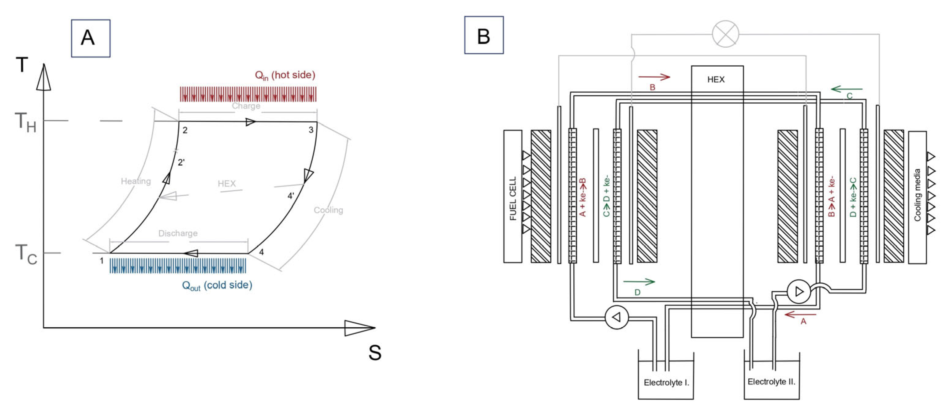
Figure 2A shows the related T-S diagram. The TREC system has four main steps [12]: The cycle starts at point 1 with the cold cell fully discharged. Heating the warm cell (1 → 2′) (Figure 2B red field) supplies energy Qin, shifting the redox equilibrium and raising the cell Voltage, charging the system. From 2′ to 2 and along 2 → 3, the warm cell operates at high temperature TH, delivering electrons to the load and generating electricity.
Next, the system cools (3 → 4′ → 4) (Figure 2B blue field) to TC, where reverse redox reactions complete the discharge. Material transport between electrodes restores the original redox states, regenerating the electrolytes and enabling continuous cyclic operation. Electron flow occurs through the external circuit, while ions recombine within the electrolytes.
The double redox couples are the basic elements of the system, and they must be chosen so that they respond with the largest possible open-circuit potential difference per unit temperature difference (this is shown in more detail in Appendix A). Essentially, this resulting potential difference causes the output useful power.
In case of continuity, an additional section is installed: the heat and electrolyte exchange section placed between the two cells, with the same assembly (Figure 2B). Here, the physical permeability between anolyte-anolyte and catholyte–catholyte electrolytes allows the material transport to occur due to the difference in concentration. The negative features of this are that the transport is naturally very slow (the sides have a diffusion constant of the order of 9−10–10−10 m2/s); on the other hand, the passage between the cold and hot sides evens out the temperature. Since the performance is proportional to the temperature difference, we also include a heat exchanger (HEX) (Figure 2).
Intake heat on the hot side (Figure 2B, left side):
Q ˙ H = T H S H
The usable part of internal energy (according to the Gibbs equation). Here, we see how much energy is extracted from the TREC at the temperature of the system, producing waste heat.
G H = H H T H S H
Assuming that the specific heat with the temperature change is nearly constant [12], in this case, according to the measurement of [13]. Also, if we are assuming that the heat capacity of the electrolyte is constant, the electrochemical potential (3) (Gibbs–Helmholtz equation):
U = G H n F = T H S H n F
Accordingly, the free energy per mole of material (which is heated, for example, by a fuel cell) can also be expressed as potential if we divide it proportionally to the Faraday constant by the number of charges that have flowed through the wire due to this heat (if the free energy of the system comes entirely from the entropy change).
For two anode–cathode pairs of the same material and different temperatures discharged [14] from each other, the potential difference between the hot and cold pairs will appear in the resistance:
U O U T o p t = T H S H n F T L S L n F = U H U L
In practice, the useful power is also limited by the system’s own internal resistance (5).
We can describe the internal resistance from
U R e s = I R i n t
Combining Equations (1)–(5), it can be seen that the useful output power of the TREC heat recovery system is given by the potential difference measured between the cold and hot states of the double electrolyte pair, considering that the internal resistance of the system is not included. In this case, the net performance (power output):
P O U T = i c A c T H S H T L S L 1 n F 2 I 2 R i n t = I ( U H U L 2 I R i n t )
Equation (6) is precise and correct if the system does not contain a heat exchanger (Figure 2A: 4′-2′ process, Figure 2B: grey ‘HEX’ box), and is called regenerative only by ion transport. If we want to stabilize its operation thermally and install a heat exchanger, this also loses heat, which is returned at the input (in the case of a countercurrent heat exchanger). In the case of regenerative types, the power recovered by the heat exchanger [12]:
Q ˙ H E X i n = 1 η H E X c p n ˙ T = ( 1 η H E X ) c p I ρ n F ( T H T L )
Since the heat exchanger losses in the system used in the experimental setup are negligible, the modified input heat equation in Equation (8) is determined by adding the heat recycled by the heat exchanger to the heat quantity on the hot side (e.g., coming from the fuel cell). Intake heat from the fuel cell (in case of η = 100%):
Q ˙ T R E C = Q ˙ i n + Q ˙ H E X i n
where we can calculate Q ˙ i n from the material properties and the heat source(s) properties, or by measurement. In case of calculations, we can use the function of conductive heat transfer:
Q ˙ i n = λ · A · ( T H T L ) d
Then, the performance of the TREC system with thermally continuous operation with the heat exchanger is similar to the version without the heat exchanger (6), but with the correct sign; the amount of heat transferred by the heat exchanger must also be taken into account, in addition to the input heat. Useful performance can also be expressed with a calculation of the intake heat from the heat exchanger:
P T R E C = I U H U L 2 I R i n t = I ( T H T L ) ( Q ˙ T R E C Q ˙ H E X i n + I 2 R i n t ) n F
The power of the pump can be omitted from this relation in the case that the ion exchange takes place in the electrolyte without an external force. The efficiency of the whole system (including the regenerative part) is as follows:
η T R E C = P T R E C Q ˙ i n
The parameters examined in the sensitivity test can be interpreted separately.
Effect of thermal coefficient: It is a crucial variable from the point of view of this manuscript, since the formation of the thermogalvanic phenomenon itself is linked to different material reactions to temperature. Typically, results from the entropy difference between the reduced and oxidized particles, we can describe it like [15]
α = d U / d t = S / n F
If we approach the electrolyte pairs from the point of view of temperature sensitivity, then the useful electrical power is obtained as the difference between the thermoelectric potential ( α c e l l T ) and the potential difference due to concentration differences ( R / n F l n B H T h / B C T C ) . Here, we already consider that the power outlined in (10) is the constant power of an ideal system; in a non-ideal case, output power depends on the concentrations at every moment. With free ion exchange (Figure 2B, middle tubes) and, if necessary, circulation, Equation (10) can be used; in the absence of these, the change in the concentration difference must be taken into account:
P m a x = α c e l l T R / n F l n B H T h / B C T C 2 / 4 ( R H R C ) = O C V H O C V C
Effect of hot side cell temperature: The warm-side temperature has a double effect. On the one hand, the higher temperature means lower resistance in the material, and it generates higher electric performance [16]:
R = R R e f / 1 + θ ( T H T R e f )
Here we set the θ fitting parameter 0.06 K-1 according to [17].
This also affects the electrical performance:
P m a x = α c e l l T R / n F l n B H T h / B C T C 2 / 4 ( R H R C ) = O C V H O C V C
As with the power, the effect of the heat exchanger must be taken into account when calculating the efficiency. In addition, in asymmetric cases, we must also take into account that the electrical resistance of the high- and low-temperature electrochemical cells is not the same. This is taken into account in Equation (16). The efficiency also changes with the change in resistance:
η T R E C = η c 1 I ( R H R L ) α c e l l T / 1 + η c ( 1 η H E X ) α c e l l Q c c p
In addition, the effect seen in Equation (4) also applies, which practically expresses the chemical balance difference due to the temperature difference and the resulting open circuit potential difference.
P T R E C = I T H S ˙ H / n F T L S ˙ L / n F = 2 I 2 R i n t
Effect of cooling temperature: The temperature on the cold side is, of course, also necessary for the temperature difference that forms the basis of the phenomenon. Effect of concentration in the electrolyte solution: At higher concentration values, the electrolyte’s resistance decreases [18].
R S 1 = C a S c η c
The effects of this on performance are detailed in Equation (14).
Effect of active membrane-electrode area: The intensity of the redox reaction depends on the active electrode surface, which can be calculated separately for the cold and hot sides, according to the charge balance equation [3]:
n F δ v = i A e
It should be noted that, based on the above equations, an expected optimum in the performance of the TREC system also arises, which we can determine in advance based on the knowledge of the internal resistance:
P O P T = i ( U H U L 2 I 2 R i n t )
Effect of heat exchanger efficiency: The heat exchanger between the cells prevents the formation of a thermal balance during the ion exchange, as the latter would also equalize the values of the open circuit potential between the cold and hot cells. The amount of heat recovered together with the total heat input can be included in the performance, as shown in Equation (7).
Effect of electrolyte’s specific heat: The specific heat of the circulated medium affects the amount of heat removed by the heat exchanger. We can model this effect with the following expression:
Q ˙ H E X i n = c p n ˙ ( 1 η H E X s ) ( T H T L )
The effect of the heat removed by the heat exchanger is shown in Equation (9), where the factor negatively affects the TREC performance.
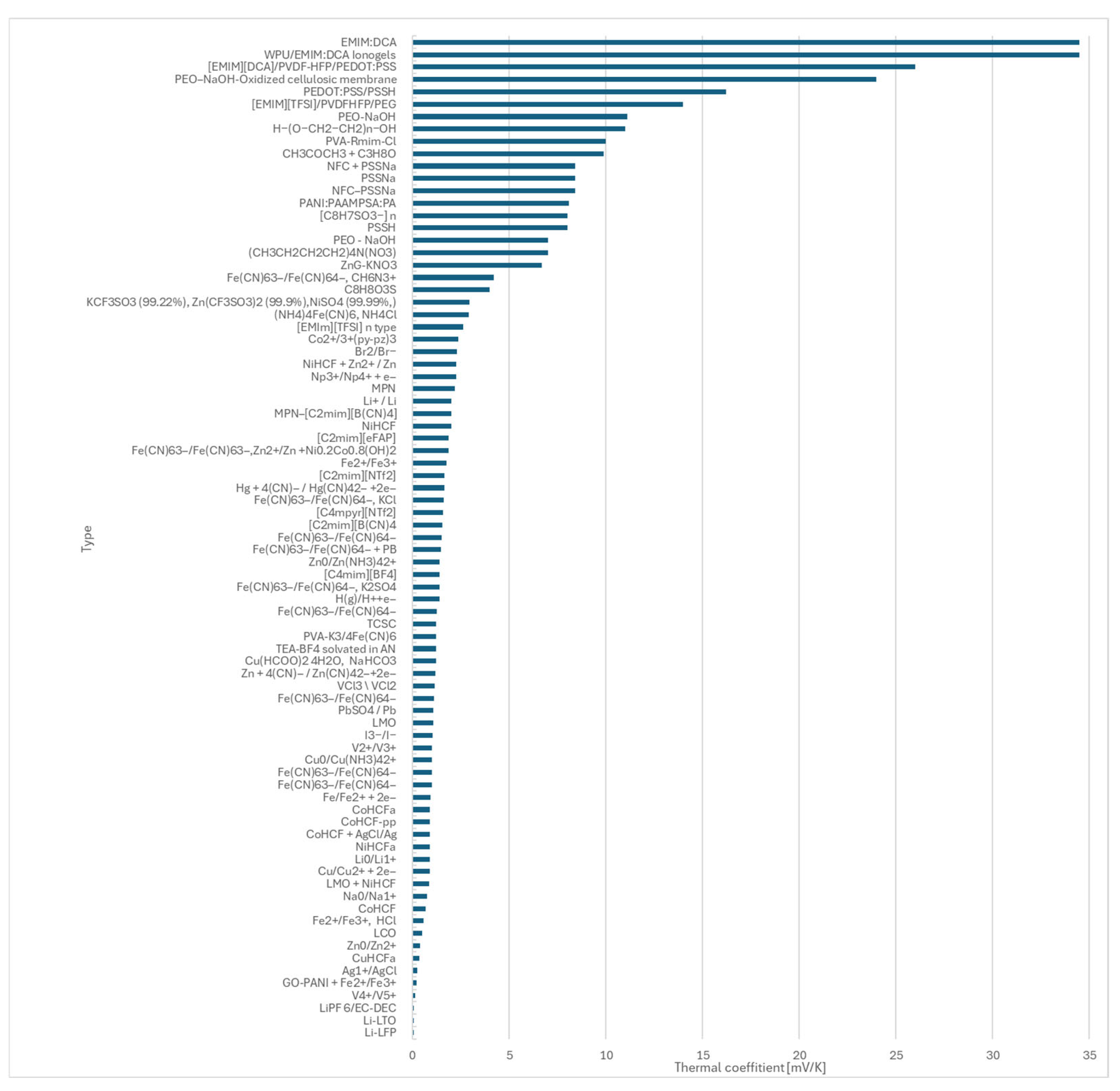
When choosing materials, it was an important aspect to work with real electrodes and electrolytes that can be used for the TREC system. Their resistance, but above all their temperature constant, is an important parameter, which is why we paid special attention to this in the literature search. The highest temperature constants from the analyzed experiments or theoretical calculations are shown in Appendix A.

2.2. Sensitivity Analysis

The presented model is an own-designed thermally regenerative electrochemical cell pair with 0.016 m2 active area. The used electrolyte pair was iodine–potassium iodine catholyte with 0.1M/1M concentration and potassium ferricyanide with potassium hexacyanoferrate 0.375M/0.375M (both aqueous soluted) [3]. The parameters (Table 3) were typically chosen in such a way that the variables take values available within the size range of the prepared TREC system. The temperature of the cold side was taken from the installation environment as cooling, so that no external energy source was needed. The hot side temperature is maximized at the maximum temperature of the PEM fuel cells.
The list of parameters differs from the nomenclature; this is because not all parameters were examined in terms of sensitivity. For a given commercial carbon felt electrode, the electrode area (A) is proportional to the tested contact area. Similarly, the electrode thickness is a fixed, given geometric parameter, and its effect on the amount of electrolyte that can be accommodated was indirectly taken into account when examining the capacity. For a given electrode, the current density and the current strength also show analogous behavior; therefore, it is sufficient to examine only the current density. Since the molar heat capacity and the cell heat capacity (Ca) are analogous concepts, I considered only the molar specific heat capacity. The degree of reaction and the degree of activity are instantaneous values, and for the reasons discussed in Equation (13), there are no or negligible effects in the concentration-balanced system outlined in Figure 2. The free energy and entropy terms are among the parameters examined, so examining them as complex terms is difficult to use in practice. The heat absorbed by the heat exchanger was also not examined in terms of sensitivity, since the efficiency of the heat exchanger is more easily selected or modified by the user in practice, and this value is also given for a given input heat quantity.
During the sensitivity tests, we examined two groups, heat-sensitive and current-sensitive members, and we examined these two variables in terms of sensitivity.
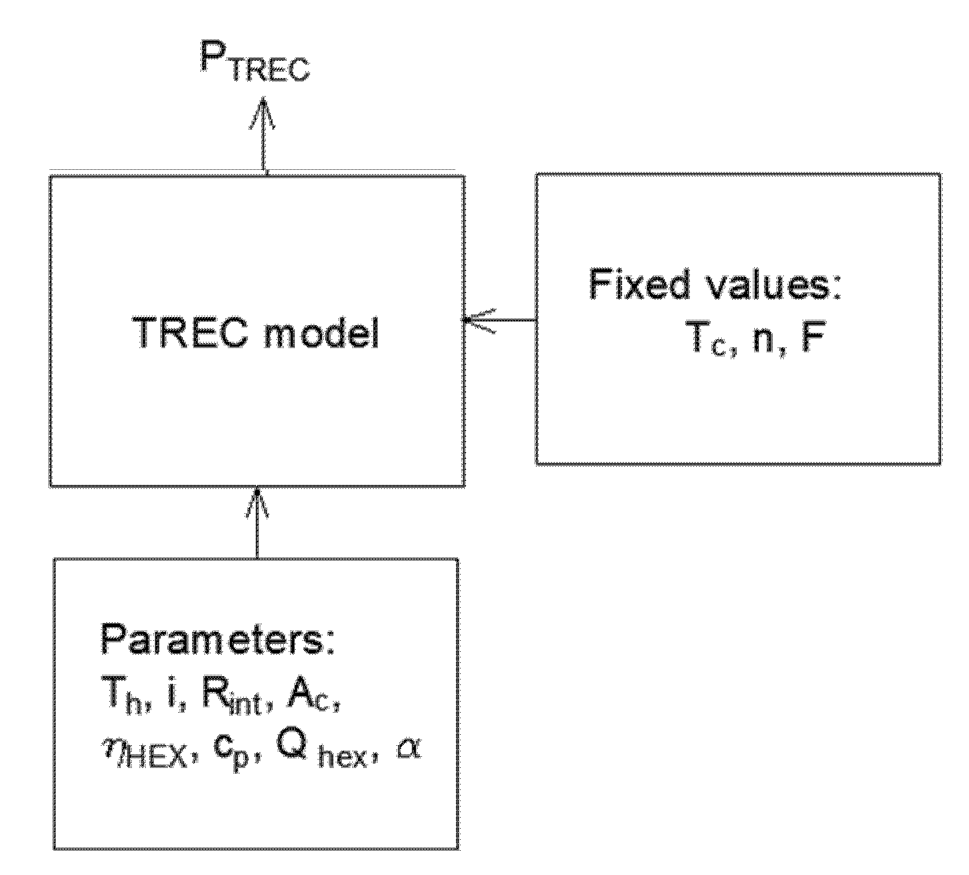
Heat and current are two parameters in relation to which all of the necessary parameters can be examined, thus aiding comparability. In each case of the study, we selected a primary trend, which, according to the MPSA approach, represents the series of observed values (Figure 3). We want to check the relative importance of each parameter. This is important because, in the experimental phase, we adjust the parameters that have a significant effect on performance to achieve higher performance. For this, the Multi-Parametric Analysis (MPSA) was used [19].
The process of conducting MPSA calculations (Figure 3) can be summarized in the following steps. First, the parameters to be tested are selected. Next, the range for each parameter is defined. Within these ranges, a series of independent, random numbers is generated for each parameter, following a uniform distribution. The model is then executed using the generated parameter series, and the objective function is calculated for each cell’s current value according to Equation (22).
f N = k = 1 j x 0 N x P N ( k ) 2
Subsequently, the relative importance of each parameter is determined for each current value using Equation (23).
σ N = f N x 0 N
Finally, parametric sensitivity is evaluated to identify sensitive and insensitive parameters, as described by Equation (24).
γ = T H = 297.15 j m a x σ H
According to the method shown in Figure 3, the program assigns a value to each independent variable according to the MPSA model, which expresses the degree of sensitivity of the given physical parameter.
For a given parameter, the higher the value of the index ‘γ’, the greater the sensitivity of the fuel cell model to that parameter. Using the index ‘γ’, the following criteria were applied to define the relative sensitivity of the fuel cell model to a specific parameter [20]. The values assigned to the parameters strength:
γ 500 The parameter is intensive
500 < γ 1,000 The parameter is semi-intensive
10,000 < γ The parameter is sensitive
The model assumptions in summarized are summarized in a version provided on the Table A1 in Appendix A.3.

3. Results

Based on the insights gained from the results (Table 4), enhancing the performance of TREC systems requires prioritizing the material properties of the selected substances, particularly their thermal constant and internal resistance. The latter is a construction parameter and a material property. If the material is given, the magnitude of the operating current is the most important. If this is limited due to the input heat or other electrotechnical properties, it is worth increasing either the input heat itself (heat side temperature) or the active membrane surface. It is also instructive that the variables related to the heat exchanger affect the performance of the TREC itself with little intensity; their effect is not in the field of performance but in the field of efficiency.
Examining the effect of the temperature on the hot side, we considered the input heat on the heating surface in such a way that it changes linearly with the current strength (Figure 4A). As an example, we chose a 2 mm-thick, 0.16 m2 aluminum sheet with a thermal conductivity of 237 W/mK, which in a real installation environment is close to a fuel cell in a car. The reason for the choice was that this system generates a small heat output (usually a maximum temperature of 80 °C); therefore, it represents a special challenge for a heat utilization task.
During the evaluation, the parameter was classified as ‘sensitive’. In practice, however, it is not advisable to increase this value, as it would also mean a decrease in the efficiency of the primary equipment. However, the contact surface and the amount of heat flowing through it can be increased by design, e.g., with a larger paved surface, or by connecting modules placed on several heated parts in series.
We also examined the effect of internal resistance on performance (Figure 4B). In the tested range, the system is sensitive to this parameter, especially in the case of higher loads, we can expect a significant change when changing the internal resistance. As expected, the current density (Figure 5A), i.e., the magnitude of the electric current falling on a unit of reactive surface, also fell into the same sensitivity category. However, this test can also be considered theoretical; in practice, this value follows the external parameters, and the user and the designer cannot influence it. It affects the active surface, which falls into the ‘Sensitive’ category (Figure 5B). Here, we used traditional solid electrodes, but based on the results, felt electrodes, which are more expensive but have an order of magnitude larger surface area, can be considered.
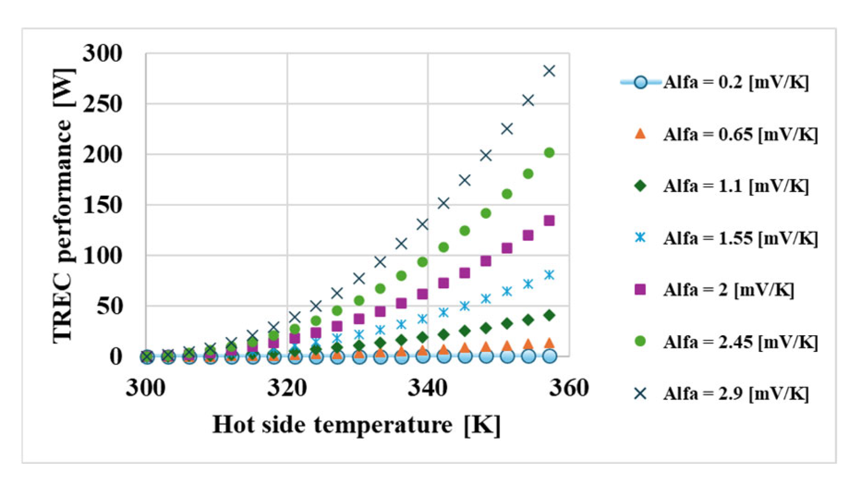
The temperature coefficient was clearly the most important parameter for the system’s performance (Figure 6). This value is characteristic of electrolyte-electrode assemblies. This is the only term whose importance increases not linearly, but exponentially with temperature. Since it is such an extremely influential factor, we performed a separate investigation to see which of the currently published materials have which temperature coefficient (Appendix A.1).
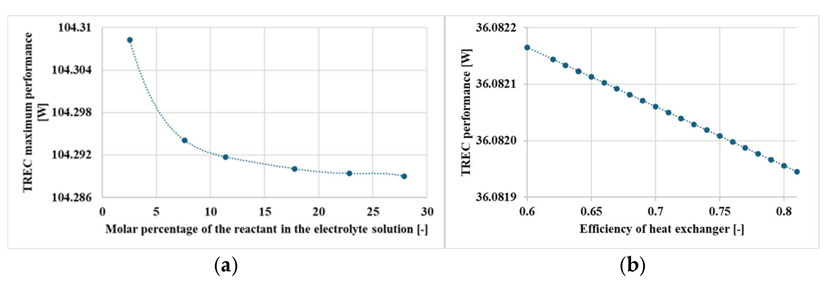
Although it has to be considered mathematically, in practice, the molar percentage of the electrolyte (Figure A2a in Appendix A.2) and the efficiency of the heat exchanger (Figure A2b in Appendix A.2) have little influence on the performance of the TREC in the investigation range, that is the reason why we can see just the individual value changing on the Figure A2a in Appendix A.2 and Figure A2b in Appendix A.2. These devices were included in the performance-focused model due to the need for completeness; in fact, they are not crucial in performance, but for continuous operation.

4. Discussion

The aim of this study is to identify the key parameters influencing the performance of thermally regenerative electrochemical cycle (TREC) systems, with a particular emphasis on the utilization of low-temperature waste heat from fuel cells. The authors conducted a sensitivity analysis based on a self-developed TREC model, employing the Multi-Parametric Sensitivity Analysis (MPSA) method. The impact of various physical and chemical parameters on system performance and efficiency was investigated using electrolyte properties and actual cell geometry.
Based primarily on the results of the sensitivity analysis:
  • The thermal coefficient of the redox couples was found to be the most critical factor affecting system performance (γ ≈ 737,800).
  • Internal resistance and current density also emerged as highly sensitive parameters, with a considerable influence on performance (γ ≈ 35,035 and γ ≈ 30,287, respectively).
  • The hot-side temperature and the size of the active membrane area were identified as sensitive parameters that play a significant role in energy conversion.
  • The efficiency of the heat exchanger and the specific heat capacity of the electrolyte have a lesser effect on performance, though they do influence overall system efficiency.
  • During the study, literature data for 81 redox couples were reviewed and compared, providing a foundation for future material selection.
Based on the sensitivity studies, we can distinguish three categories: the construction parameters include the resistance of the electrodes and the active membrane surface. These are highly sensitive values in themselves and indicate that they are worth considering geometrically in the design. If we only have the option of one, we increase the active surface when working with a current collector, including the contact surface. This means that the contact resistance is a critical parameter between the electrode surface and the current collection point, which must be minimized. The construction parameters include the heat exchanger, whose impact on performance is small, but we would like to emphasize that its importance in terms of efficiency and service life should not be neglected.
Chemical variables such as thermal coefficient and molar capacity yielded mixed results, which led to the conclusion that it is definitely worth pairing multiple electrolytes so that their combined thermal coefficient is as high as possible, even if their molar heat capacity is not as favorable.
The more difficult to influence parameters, which result from the instantaneous behavior of the external system (hot side temperature, current), are extremely sensitive or sensitive. We have little influence on these when designing. The lesson to be learned is that these are such influential variables that we will not be able to compensate for them with e.g., chemical parameters with low sensitivity (e.g., more expensive electrolyte).
The results were classified into construction and material categories, which helps us predict the extent of deviations from the basic model in similar calculations of significantly different but identically functioning constructions. The model’s verifiable scalability enables its application to systems of various sizes and capacities, including both automotive and industrial contexts. Future research directions include extending the model to account for dynamic operating conditions—for instance, to explore heat generation in vehicles under variable loads. Experimental validation of selected redox couples could enhance practical applicability and support material development efforts. The system may also be integrated into hybrid energy storage or heat recovery solutions, such as heat pumps or supercapacitors. Furthermore, the methodology is adaptable to other low-temperature heat sources, including waste heat from data centers or industrial cooling water.

5. Patents

This research was funded by Project no. RRF-2.3.1-21-2022-00009, titled the National Laboratory for Renewable Energy, and has been implemented with the support provided by the Recovery and Resilience Facility of the European Union within the framework of Program Széchenyi Plan Plus.
Prepared With the Professional Support of the Co-operative Doctoral Program of the University Research Scholarship Program of The Ministry of Culture and Innovation, financed from the National Research, Development and Innovation Fund.

Author Contributions

Conceptualization, Á.B. and E.L.; Methodology, E.L.; Validation, E.L.; Formal analysis, Á.B. and E.L.; Investigation, E.L.; Resources, E.L.; Data curation, E.L.; Writing—original draft, Á.B. and E.L.; Writing—review and editing, E.L.; Visualization, Á.B. and E.L.; Supervision, Á.B. and E.L.; Project administration, Á.B. and E.L.; Funding acquisition, E.L. All authors have read and agreed to the published version of the manuscript.

Funding

This research received no external funding.

Data Availability Statement

The raw data supporting the conclusions of this article will be made available by the authors on request.

Conflicts of Interest

The authors declare no conflicts of interest.

Appendix A

Appendix A.1

Figure A1. Thermal coefficient of different electrolytes [21,22,23,24,25,26,27,28,29,30,31,32,33,34,35,36,37,38,39,40,41,42,43,44,45,46,47,48,49,50,51,52,53,54,55,56,57,58,59,60,61,62,63,64,65,66,67,68,69,70].
Energies 18 05422 g0a1

Appendix A.2

Figure A2. Change of expected performance with the change of molar percentage of reactant in the solution (a) and with change of efficiency of the heat exchanger (b).
Energies 18 05422 g0a2

Appendix A.3

Table A1. Assumptions and justifications of the calculation.
AssumptionJustificationFixed Value(s)
Constant specific and molar heat capacityVariation in the studied temperature range is smallcp = 75.6 J/(mol·K) (test: 58.15–80.77)
Free energy fully derived from entropy changeApplied Gibbs–Helmholtz approximation
Heat transfer only by conductionBased on aluminum plate conductionλ = 237 W/mK; thickness = 2 mm; area = 0.16 m2
Neglected pump powerIon exchange occurs by diffusion, no external drivingDiffusion constant, around 10−9; 10−10 m2/s
Constant, symmetric internal resistanceAssumed identical in both cellsRint = RH = RC = 24.5 Ω (test: 5.14–24.25)
Fixed cold-side temperature, fixed humidityTaken from environment, no external coolingTC = 297.15 K (24 °C)
Hot-side temperature limited by PEM cellLimited by PEM fuel cell maximum operating temperatureTH = 357.15 K (84 °C); test: 297.15–360.15 K
Fixed electrolyte pairIodine–KI and ferricyanide–hexacyanoferrate aqueous solutions0.1/1 M (I2–KI); 0.375/0.375 M (Fe(CN)63−/Fe(CN)64−)
Heat generated by fuel cell is fix and constantRepresents the external heat sourceQFC = 50,000 J (test: 23,750–50,000 J)

References

  1. Reay, D. Heat Recovery Systems; Library of Congress Cataloging in Publication Data; Spon Press: London, UK, 1979; ISBN 0419114009. [Google Scholar]
  2. Wilberforce, T.; Muhammad, I. Dynamic modelling and analysis of Organic Rankine Cycle power units for the recovery of waste heat from 110kW Proton Exchange Membrane Fuel cell system. Int. J. Thermofluids 2023, 17, 100280. [Google Scholar] [CrossRef]
  3. Qian, X.; Shin, J. Thermally regenerative electrochemically cycled flow batteries with pH neutral electrolytes for harvesting low-grade heat. Phys. Chem. Chem. Phys. 2021, 23, 22501–22514. [Google Scholar] [CrossRef]
  4. Hassan, A.; Corberán, J.; Ramirez, M.; Trebilcock-Kelly, F.; Payá, J. A high-temperature heat pump for compressed heat energy storage applications: Design, modeling, and performance. Energy Rep. 2022, 8, 10833–10848. [Google Scholar] [CrossRef]
  5. Kim, D.; Lee, J.; Kim, J.; Kim, M.S.; Kim, M.S. Parametric study and performance evaluation of an organic Rankine cycle (ORC) system using low-grade heat at temperatures below 80 °C. Appl. Energy 2017, 189, 55–65. [Google Scholar] [CrossRef]
  6. Luo, D.; Zhang, H.; Li, Z.; Zhang, P.; Chen, H. Increasing waste heat recovery performance of a hexagonal thermoelectric generator with microchannels. Energy 2025, 334, 137589. [Google Scholar] [CrossRef]
  7. Ridwan, M.; Gasulla, M.; Reverter, F. Principle and Applications of Thermoelectric Generators: A Review. Sensors 2025, 25, 2484. [Google Scholar] [CrossRef] [PubMed]
  8. IBISWorld. Total Price of Semiconductor and Electronic Components; Business Environment Profiles; IBISWorld: London, UK, 2025. [Google Scholar]
  9. Macrotrends. Copper Prices (1959–2025). 2025. Available online: https://www.macrotrends.net/1476/copper-prices-historical-chart-data (accessed on 8 August 2025).
  10. Hamid, K.; Sajjad, U.; Ahrens, M.U.; Ren, S.; Ganesan, P.; Tolstorebrov, I.; Arshad, A.; Said, Z.; Hafner, A.; Wang, C.-C.; et al. Potential evaluation of integrated high temperature heat pumps: A review of recent advances. Appl. Therm. Eng. 2023, 230, 120720. [Google Scholar] [CrossRef]
  11. de Bethune, A.; Licht, T.; Swendeman, N. The Temperature Coefficients of Electrode Potentials: The Isothermal and Thermal Coefficients—The Standard Ionic Entropy of Electrochemical Transport of the Hydrogen Ion. J. Electrochem. Soc. 1959, 106, 616–625. [Google Scholar]
  12. Long, R.; Li, B.; Liu, Z.; Liu, W. Multi-objective optimization of a continuous thermally regenerative electrochemical cycle for waste heat recovery. Energy 2015, 93, 1022–1029. [Google Scholar] [CrossRef]
  13. Lee, S.; Yang, Y.; Ghasemi, H.; Kraemer, D.; Cheng, G.; Ciu, Y. An electrochemical system for efficiently harvesting low-grade heat energy. Nat. Commun. 2014, 5, 3942. [Google Scholar] [CrossRef]
  14. Long, R.; Li, B. A hybrid system using a regenerative electrochemical cycle to harvest waste heat from the proton exchange membrane fuel cell. Energy 2015, 93, 2079–2086. [Google Scholar] [CrossRef]
  15. Zhang, H.; Wang, Q. Thermally regenerative electrochemical cycle for low-grade heat harnessing. Chem. Phys. Rev. 2021, 2, 021304. [Google Scholar] [CrossRef]
  16. Gao, C.; Lee, S.; Yang, Y. Thermally regenerative electrochemical cycle for low-grade heat harvesting. ACS Energy Lett 2017, 2, 2326–2334. [Google Scholar] [CrossRef]
  17. Bleeker, J.; Reichert, S.; Veerman, J.; Vermaas, D. Thermo-electrochemical redox flow cycle for continuous conversion of low-grade waste heat to power. Sci. Rep. 2022, 12, 7993. [Google Scholar] [CrossRef] [PubMed]
  18. Inoue, D.; Moritomo, Y. Concentration dependence of resistance components in solutions containing dissolved Fe2+/Fe3+. RSC Adv. 2024, 14, 6292–6297. [Google Scholar] [CrossRef] [PubMed]
  19. Choi, J.; Harwey, J.; Conclin, M. Use of multi- parameter sensitivity analysis to determine relative importance of factors influencing natural attenuation of mining contaminants. In Proceedings of the Toxic Substances Hydrology Program Meeting, Charleston, SC, USA, 8–12 March 1999. [Google Scholar]
  20. Correa, J.; Farret, F.; Popov, F.; Simoes, M. Sensitivity Analysis of the Modeling Parameters Used in Simulation of Proton Exchange Membrane Fuel Cells. IEEE Trans. Energy Convers. 2005, 20, 211–218. [Google Scholar] [CrossRef]
  21. Wang, H.; Kim, S.; Rojas, T.; Zhu, Y.; Li, Y.; Xu, K.; Ngo, A.; Ciu, Y. Correlating Li-Ion Solvation Structures and Electrode PotentialTemperature Coefficients. J. Am. Chem. Soc. 2021, 143, 2264–2271. [Google Scholar] [CrossRef]
  22. Maldifassi, J.; Russell, J.; Kim, J.; Brightman, E.; Chen, X.; Bae, D. Evaluation of redox pairs for low-grade heat energy harvesting with a thermally regenerative cycle. Energy Adv. 2024, 3, 2877–2886. [Google Scholar] [CrossRef]
  23. Wang, X.; Huang, Y.; Liu, C.; Mu, K.; Li, K.; Wang, S.; Yang, Y.; Lei, W.; Su, C.; Feng, S. Direct thermal charging cell for converting low-grade heat to electricity. Nat. Commun. 2019, 10, 4151. [Google Scholar] [CrossRef]
  24. Linford, P.; Xu, L.; Huang, B.; Shao-Horn, Y.; Thompson, C. Multi-cell thermogalvanic systems for harvesting energy from cyclic temperature changes. J. Power Sources 2018, 399, 429–435. [Google Scholar] [CrossRef]
  25. Quickenden, T.; Mua, Y. A Review of Power Generation in Aqueous Thermogalvanic Cells. J. Electrochem. Soc. 1995, 12, 3985. [Google Scholar] [CrossRef]
  26. Jiang, J.; Tian, H.; He, X.; Zeng, Q.; Niu, Y.; Zhou, T.; Yang, Y.; Wang, C. A CoHCF system with enhanced energy conversion efficiency for low-grade heat harvesting. J. Mater. Chem. A 2019, 7, 23862–23867. [Google Scholar] [CrossRef]
  27. Yuan, Z.; Yu, Y.; Li, W.; Wang, C.; Zhong, X.; Sui, X.; Yu, Z.; Han, D.; Shon, H.; Chen, Y. Thermo-osmosis-Coupled Thermally Regenerative Electrochemical. Cycle Effic. Lithium Extr. 2021, 13, 6276–6285. [Google Scholar] [CrossRef]
  28. Pereira, E.; Andrade, D.; Haas, V.; Watanabe, E.; Cunha, C.; de Sousa, A. Measuring the Self-Efficacy of Health Professionals for Practicing Hand Hygiene and Using Gloves: Development and Validation of an Instrument. Sustainability 2022, 14, 9486. [Google Scholar] [CrossRef]
  29. Gao, C.; Yin, Y.; Zheng, L.; Liu, Y.; Sim, S.; He, Y.; Zhu, C.; Liu, Z.; Lee, H.; Yuan, Q.; et al. Engineering the Electrochemical Temperature Coefficient for Efficient Low-Grade Heat Harvesting. Adv. Funct. Mater. 2018, 28, 1803129. [Google Scholar] [CrossRef]
  30. Park, H.; Licon, C.; Sleipness, O. Teaching Sustainability in Planning and Design Education: A Systematic Review of Pedagogical Approaches. Sustainability 2022, 14, 9485. [Google Scholar] [CrossRef]
  31. Ikeshoji, T. Thermoelectric Conversion by Thin-Layer Thermogalvanic Cells with Soluble Redox Couples. Bull. Chem. Soc. Jpn. 2006, 60, 1505–1514. [Google Scholar] [CrossRef]
  32. Ikeshoji, T.; Kimura, S.; de Nahui, F.; Yoneya, M. Computer analysis of natural convection in thin-layer thermocells with a soluble redox couple: Part 1. Method and the unsteady problem. J. Electroanal. Chem. Interfacial Electrochem. 1991, 307, 29–45. [Google Scholar] [CrossRef]
  33. Liu, Y.; Gao, C.; Sim, S.; Kim, M.; Lee, S. Lithium Manganese Oxide in an Aqueous Electrochemical Systemfor Low-Grade Thermal Energy Harvesting. Chem. Mater. 2019, 31, 4379–4384. [Google Scholar] [CrossRef]
  34. Vassel, S.; Vassel, N. Electrochemical way of converting low-grade heat energy into electricity based on crystalline hydrate melting and crystallization. Int. J. Heat Mass Transf. 2018, 122, 818–822. [Google Scholar] [CrossRef]
  35. Hornut, J.; Storck, A. Experimental and theoretical analysis of a thermogalvanic undivided flow cell with two aqueous electrolytes at different temperatures. J. Appl. Electrochem. 1991, 21, 1103–1113. [Google Scholar] [CrossRef]
  36. Reynard, D.; Dennison, C.; Battistel, A.; Girault, H. Efficiency improvement of an all-vanadium redox flow battery by harvesting. J. Power Sources 2018, 390, 30–37. [Google Scholar] [CrossRef]
  37. Cortesi, A.; Dijoux, L.; Bris, G.; Pénicaud, C. Explaining the Differences between the Environmental Impacts of 44 French Artisanal Cheeses. Sustainability 2022, 14, 9484. [Google Scholar] [CrossRef]
  38. Chum, H.; Fahlsing, R.; Jayadev, T. Analysys of the Application of Thermogalvanic Cells to the Conversion of Low Grade Heat to Electrochemistry; Solar Energy Research Institute, A Division of Midwest Research Institute: Lakewood, CO, USA, 1980. [Google Scholar]
  39. Wang, X.; Feng, S. Thermal Capacitive Electrochemical Cycle on Carbon-Based Supercapacitor for Converting Low-grade Heat to Electricity. Front. Mech. Eng. 2017, 3, 20. [Google Scholar] [CrossRef]
  40. Kundu, A.; Fisher, T. Harnessing the thermogalvanic effect of the ferro/ferricyanide redox couple in a thermally chargeable supercapacitor. Electrochem. Acta 2018, 281, 357–369. [Google Scholar] [CrossRef]
  41. Chen, D.; Li, Z.; Jiang, J.; Wu, J.; Shu, N.; Zhang, X. Influence of electrolyte ions on rechargeable supercapacitor for high value-added conversion of low-grade waste heat. J. Power Sources 2020, 465, 228263. [Google Scholar] [CrossRef]
  42. Ikeshoji, T.; Gonçalves, R. Thermogalvanic cells with aqueous redox couples and temperature differences larger than 100 K. J. Appl. Electrochem. 1993, 23, 516–519. [Google Scholar] [CrossRef]
  43. Burmistrov, I.; Khanna, R.; Gorshkov, N.; Kiselev, N.; Artyukhov, D.; Boychenko, E.; Yudin, A.; Konyukhov, Y.; Kravchenko, M.; Gorokhovsky, A.; et al. Advances in Thermo-Electrochemical (TEC) Cell Performances for Harvesting Low-Grade Heat Energy: A Review. Sustainability 2022, 14, 9483. [Google Scholar] [CrossRef]
  44. Abraham, J.; Douglas, R.; Pringle, M. High Seebeck coefficient redox ionic liquid electrolytes for thermal energy harvesting. Energy Environ. Sci. 2013, 6, 2639–2645. [Google Scholar] [CrossRef]
  45. Yang, Y.; Lee, S.; Ghasemi, H.; Loomis, J.; Li, X.; Kraemer, D.; Zheng, G.; Cui, Y.; Chen, G. Charging-free electrochemical system for harvesting low-grade thermal energy. Appl. Phys. Sci. 2014, 111, 17011–17016. [Google Scholar] [CrossRef]
  46. Quickenden, T.; Vernon, C. Thermogalvanic conversion of heat to electricity. Sol. Energy 1986, 36, 63–72. [Google Scholar] [CrossRef]
  47. Sun, G.W. A Nickel Hexacyanoferrate Based Thermo-Electrochemical Device For Efficient Heat-to-Electricity Conversion. Master’s Thesis, Department of Mechanical Engineering Massachusetts Institute of Technology, Cambridge, MA, USA, 2019. Available online: https://hdl.handle.net/1721.1/122229 (accessed on 10 August 2025).
  48. Lazar, M.; Al-Masri, D.; MacFarlane, D.; Pringle, J. Enhanced thermal energy harvesting performance of a cobalt redox couple in ionic liquid–solvent mixtures. Phys. Chem. Chem. Phys. 2016, 18, 1404–1410. [Google Scholar] [CrossRef]
  49. Kim, K.; Lee, H. Diglyme-Based Thermoelectrochemical Cells Operable at Both Subzero and Elevated Temperatures. Energy Technol. 2019, 7, 1900857. [Google Scholar] [CrossRef]
  50. Cheng, C.; Wang, S.; Tan, P.; Dai, Y.; Yu, J.; Cheng, R.; Feng, S.; Ni, M. Insights into the thermopower of thermally regenerative electrochemical cycle for low grade heat harvesting. ACS Energy Lett. 2020, 6, 329–336. [Google Scholar] [CrossRef]
  51. Al-Masri, D.; Dupont, M.; Yunis, R.; MacFarlane, D.; Pringle, J. The electrochemistry and performance of cobalt-based redox couples for thermoelectrochemical cells. Electrochim. Acta 2018, 269, 714–723. [Google Scholar] [CrossRef]
  52. Liu, Y.; Wang, H.; Sherrell, P.; Liu, L.; Wang, Y.; Chen, J. Potentially Wearable Thermo-Electrochemical Cells for Body Heat Harvesting: From Mechanism, Materials, Strategies to Applications. Adv. Sci. 2021, 8, 2100669. [Google Scholar] [CrossRef]
  53. Hammond, R.; Risen, W. An electrochemical heat engine for direct solar energy conversion. Sol. Energy 1979, 23, 443–449. [Google Scholar] [CrossRef]
  54. Sun, X.; Chen, H.; Li, Y.; Zeng, D.; Qiu, P.; Zeng, H.; Ji, X.; Chen, L.; Shi, X. Efficient Harvesting Waste Heat by Zn-Ion Battery Under Thermally Regenerative Electrochemical Cycles. Adv. Mater. 2025, 37, 2418482. [Google Scholar] [CrossRef] [PubMed]
  55. Wang, H.; Zhao, D.; Khan, Z.; Puzinas, S.; Jonsson, M.; Berggren, M.; Crispin, X. Ionic Thermoelectric Figure of Merit for Charging of Supercapacitors. Adv. Electron. Mater. 2017, 3, 1700013. [Google Scholar] [CrossRef]
  56. Duan, J.; Feng, G.; Yu, B.; Li, J.; Chen, M.; Yang, P.; Feng, J.; Liu, K.; Zhou, J. Aqueous thermogalvanic cells with a high Seebeck coefficient for low-grade heat harvest. Nat. Commun. 2018, 9, 5146. [Google Scholar] [CrossRef]
  57. Wang, Q.; Liu, P.; Zhou, F.; Gao, L.; Sun, D.; Meng, Y.; Wang, X. Zinc-Guided 3D Graphene for Thermally Chargeable Supercapacitors to Harvest Low-Grade Heat. Molecules 2022, 27, 1239. [Google Scholar] [CrossRef]
  58. Bonetti, M.; Nakamae, S.; Roger, M.; Guenoun, P. Huge Seebeck coefficients in nonaqueous electrolytes. J. Chem. Phys. 2011, 134, 114513. [Google Scholar] [CrossRef]
  59. Zhao, D.; Fabiano, S.; Berggren, M.; Crispin, X. Ionic thermoelectric gating organic transistors. Nat. Commun. 2017, 8, 14214. [Google Scholar] [CrossRef]
  60. Kim, S.; Lin, H.; Yu, C. Thermally Chargeable Solid-State Supercapacitor. Adv. Energy Mater. 2016, 6, 1600546. [Google Scholar] [CrossRef]
  61. Akbar, Z.; Jeon, J.; Jang, S. Intrinsically self-healable, stretchable thermoelectric materials with a large ionic Seebeck effect. Energy Environ. Sci. 2019, 13, 2915–2923. [Google Scholar] [CrossRef]
  62. Jiao, F.; Naderi, A.; Zhao, D.; Schlueter, J.; Shahi, M.; Sundström, J.; Granberg, H.; Edberg, J.; Ail, U.; Brill, J.; et al. Ionic thermoelectric paper. J. Mater. Chem. A 2017, 5, 16883–16888. [Google Scholar] [CrossRef]
  63. Zhou, H.; Liu, P. High Seebeck Coefficient Electrochemical Thermocells for EfficientWaste Heat Recovery. ACS Appl. Energy Mater. 2018, 1, 1424–1428. [Google Scholar] [CrossRef]
  64. Horike, S.; Wei, Q.; Kirihara, K.; Mukaida, M.; Sasaki, T.; Koshiba, Y.; Fukushima, T.; Ishida, K. Outstanding Electrode-Dependent Seebeck Coefficients in Ionic Hydrogels for Thermally Chargeable Supercapacitor near Room Temperature. ACS Appl. Mater. Interfaces 2020, 12, 43674–43683. [Google Scholar] [CrossRef] [PubMed]
  65. Zhao, D.; Wang, H.; Khan, Z.; Chen, J.; Gabrielsson, R.; Jonsson, M.; Berggren, M.; Crispin, X. Ionic thermoelectric supercapacitors. Energy Environ. Sci. 2016, 9, 1450–1457. [Google Scholar] [CrossRef]
  66. Zhao, D.; Martinelli, A. Polymer gels with tunable ionic Seebeck coefficient for ultra-sensitive printed thermopiles. Nat. Commun. 2019, 1, 1093. [Google Scholar] [CrossRef]
  67. Kim, B.; Na, J.; Lim, H.; Kim, Y.; Kim, J.; Kim, E. Robust High Thermoelectric Harvesting Under a SelfHumidifying Bilayer of Metal Organic Framework and. Thermoelectr. Harvest. 2019, 29, 1807549. [Google Scholar] [CrossRef]
  68. Wang, S.; Li, F.; Easley, A.; Lutkenhaous, J. Real-time insight into the doping mechanism of redox-active organic radical polymers. Nat. Mater. 2019, 18, 69–75. [Google Scholar] [CrossRef] [PubMed]
  69. Cheng, H.; Ouyang, J. Ultrahigh Thermoelectric Power Generation from Both Ion Diffusion by Temperature Fluctuation and Hole Accumulation by Temperature Gradient. Adv. Energy Mater. 2020, 10, 2001633. [Google Scholar] [CrossRef]
  70. Fang, Y.; Cheng, H.; He, H.; Wang, S.; Li, J.; Yue, S.; Zhang, L.; Du, Z.; Ouyang, J. Stretchable and Transparent Ionogels with High Thermoelectric Properties. Adv. Funct. Mater. 2020, 30, 2004699. [Google Scholar] [CrossRef]
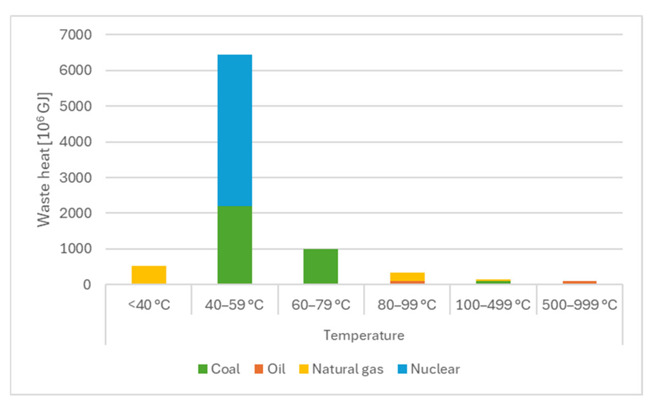
Figure 1. Primer waste heat produced by EU in different industrial sectors (data from 2018). Based on [10].
Energies 18 05422 g001
Figure 2. T-S diagram of the TREC process based on [12] (A), TREC schematic model (B), (A, B, C, and D on picture “B” are the electrolyte components, ’k’ is the number of electrons).
Energies 18 05422 g002
Figure 3. Process of sensitivity analysis.
Energies 18 05422 g003
Figure 4. Effect of change of hot side temperature (A) and internal resistance (B).
Energies 18 05422 g004
Figure 5. Effect of change of current density (A) and active area (B).
Energies 18 05422 g005
Figure 6. Effect of thermal coefficient.
Energies 18 05422 g006
Table 1. Nomenclature of the used variables.
Nomenclature
SymbolDescriptionUnit
AContact aream2
AcElectrode active aream2
αSigned sum of thermal coefficients of the cellsV/K
BHTHActivity ratio in hot cell
BCTCActivity ratio in cold cell
CaCapacitanceF
cSpecific heat
cpMolar heat capacity of electrolyteJ/(mol·K)
dWidth of the contact areasm
δReaction rate
fObjective function
fNObjective function (indexed)
FFaraday constantC/mol
GxGibbs energy
HxEnthalpy
iCurrent densityA/cm2
ICurrentA
kLoop variable
λThermal conductivityW/(m·K)
nNumber of electrons transferred
ηConcentration-dependent viscosityPa·s
ηXEfficiency%
ρDensity of electrolytekg/m3
RxInner resistanceΩ
SxEntropy
σNImportance value
TxHot side temperatureK
θFitting parameter
Ux(Electrochemical) potential, VoltageV
VxVoltageV
QxHeatJ
ΔQHEXHeat absorbed in heat exchangerJ
γRelative sensitivity
x0NObserved values
xPNModeled values
Table 2. Used subscripts and superscripts.
Subscripts and Superscripts
SymbolDescription
CCold side
cConcentration
FCFuel cell
HHot side
HEXHeat exchanger
inInlet
int.Internal
LLower
NParametric index
opt.Optimal
OUTOutlet
pIsobar
refReference
ResResistive
TRECThermally regenerative electrochemical cycle system
VVolumetric
Table 3. List of variables and fixed values.
ParameterNameUnitTest RangeValue (If Fixed)
AcElectrode active aream20.016; 0.0360.016
αSigned sum of thermal coefficients of the cellsV/K0.2 ×1 0−3; 3.2 × 10−31.44 × 10−3
cpMolar heat capacity of electrolyteJ/(mol K)58.15; 80.7775.6
FFaraday constantC/mol96.48596.485
iCurrent densityA/cm20.0002; 0.0060.0061
λThermal conductivityW/mK237237
nNumber of electrons transferred-22
QFCHeat generated by fuel cellJ23,750; 50,00050,000
QinInlet heat to the TRECJ0; 199,08050,000
RCCold cell resistance5.14; 24.2524.5
RHHot cell resistance5.14; 24.2524.5
RintInner resistance5.14; 24.2524.5
TCCold side temperatureK297.15297.15
THHot side temperatureK297.15; 360.15357.15
ηHEXEfficiency of heat exchanger-0.6; 0.80.7
Table 4. Result of sensitivity analysis. (Red: Sensitive parameters, Green: Highly sensitive parameters, Blue: Intensive parameters).
DependencyVariableSensitivity FactorSensitivity Category
CurrentHot side temperature1454.7Sensitive
Resistance of electrodes35,035.1Highly sensitive
TemperatureCurrent30,287.3Highly sensitive
Active membrane area552.1Sensitive
Thermal coefficient737,799.5Highly sensitive
Molar capacity28.5Intensive
Efficiency of HEX7.64 × 10−8Intensive
Disclaimer/Publisher’s Note: The statements, opinions and data contained in all publications are solely those of the individual author(s) and contributor(s) and not of MDPI and/or the editor(s). MDPI and/or the editor(s) disclaim responsibility for any injury to people or property resulting from any ideas, methods, instructions or products referred to in the content.