Abstract
Annular combustors are widely used in newly developed aero-engines. Nevertheless, the development of annular combustors requires substantial air supplies and high-power heaters during testing, leading to high experimental costs. To reduce these costs during the design phase, researchers often simplify annular combustors into single-dome configurations using aerodynamic and thermodynamic similarity principles. A fundamental divergence exists between the boundary conditions of annular and simplified single-dome combustors, which is reviewed in this article. It highlights the limitations of single-dome model combustors in accurately representing the crucial features of annular combustors, particularly flame–flame interaction (FFI) and jet–jet interaction (JJI). FFI and JJI existing in annular combustors are observed to result in alternating flow patterns and the superposition of mass and energy transfer between adjacent domes, which can deteriorate flame stabilization and increase NOx emissions. This review emphasizes the characteristics of multi-dome combustors and notes a lack of research comparing single-dome and multi-dome combustors under engine-relevant conditions. Addressing this research gap in the future can better connect fundamental combustion research and engine development, providing more guidance for engine designers.
1. Introduction
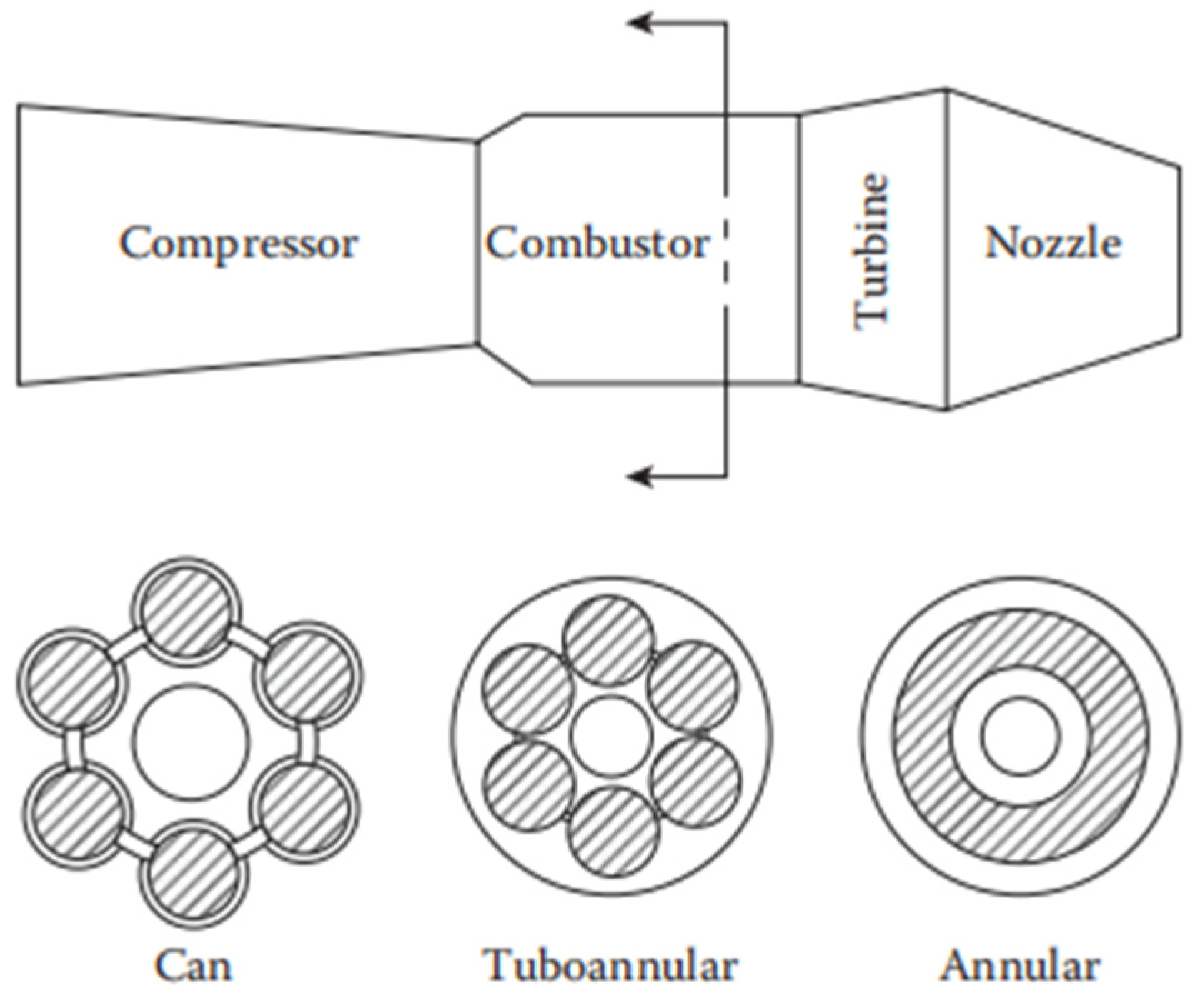
In the early years, there were two major types of aero-engine gas turbine combustors: can and annular. Can combustors, characterized by their mature technology, required less time and cost for research and development. However, the additional weight from the can flame tube casing restricted their application in aero-engines. Annular combustors, on the other hand, encountered challenges such as outer liner buckling, necessitating the use of high-strength material to prevent deformation. With the increasing demands for combustion efficiency and emissions performance of aero-engines, there was a need for higher pressure ratios at the combustor inlet. To address this issue, tuboannular combustors were introduced, which combined the compactness of annular combustors with the structural robustness of can combustors, thereby significantly reducing air flow requirements for testing. By accommodating multiple can flame tubes within a single casing, tuboannular combustors offered reduced length and weight compared to can combustors, gradually gaining prominence. However, the incorporation of cross-fire tubes and the complexity of their flow characteristics posed challenges to the design of the combustor diffusers.
Since the 1960s, advancements in material science and combustion simulation have significantly facilitated the design and optimization of annular combustors, establishing them as the preferred option. The concentric installation of the flame tube and casing enables them to achieve lower pressure losses and a more compact structure compared to the other combustor types. This configuration guarantees superior aerodynamic, thermodynamic, and combustion characteristics. Consequently, annular combustors are currently extensively utilized in newly developed aero-engines [1]. The three major combustor types are illustrated in Figure 1.
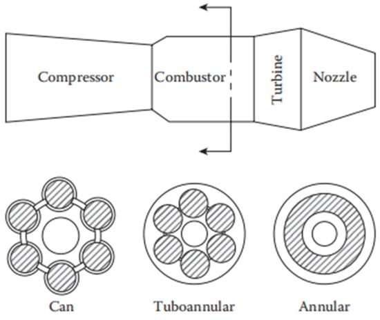
Figure 1.
Illustration of three main combustor types [1].
Nevertheless, the development of annular combustors entails the utilization of substantial air supplies and high-power heaters, thereby incurring significant experimental expenses. To mitigate these costs during the component design phase, annular combustors are frequently simplified into single-dome configurations based on similarity principles of the aerodynamic and thermodynamic parameters. This simplification involves the introduction of metal solid walls, i.e., side liners, on both sides of the studied sector. These walls compress the flow and hinder the mass and energy exchange inherent in annular combustors between neighboring domes. Additionally, the side liners are generally air-cooled to a temperature that is lower than the flame temperature. Consequently, heat transfer between the flame and sidewall can induce flame quenching [2]. The cooling air also interacts with the mainstream air and flame, thereby affecting the chemistry adjacent to the wall.
The significant impact of solid sidewalls and cooling airflow on the flow characteristics, thermochemical state, and combustion efficiency in the near-wall region has garnered extensive attention in research. These studies have highlighted fundamental disparities in flow and combustion behaviors between simplified laboratory combustors and realistic annular combustors, establishing two pivotal boundary conditions: flame–wall interaction (FWI) and flame–cooling air interaction (FCAI). A large body of literature has been devoted to these two topics [3,4,5,6,7], with notable contributions from Dreizler and co-workers, who have conducted in-depth explorations into FWI [8,9,10,11,12,13,14,15,16,17,18] and FCAI [19,20,21,22,23] using advanced optical measurement techniques. Therefore, they will not be reviewed in detail here.
Within multi-dome combustors, the flow and combustion characteristics of the middle dome are less affected by the side liners and cooling air, attributed to the isolation effect from its adjacent domes. Interactions between the middle dome and the other domes also reflect realistic interplay among neighboring sectors within an annular combustor, with similar aerodynamic and thermodynamic processes. As the experimental capabilities of several laboratories have escalated, multi-dome combustors have become the focus of many studies. In these combustors, airflow initiates expansion from the swirler outlet along the streamwise direction, resulting in interactions among domes at some downstream location. Each dome generates its own recirculation zone and flame, and shear layers are formed in the border regions. Within these shear layers, intense mass and energy exchange occurs between adjacent domes, fostering interactions between turbulent flows and combustion chemical reactions, which eventually influence the overall combustor performance. In contrast to single-dome combustors, the flow, spray, and flame in multi-dome combustors exhibit greater complexity, where the interaction between adjacent domes is often termed as flame–flame interaction (FFI) or jet–jet interaction (JJI). It should be noted that FFI and JJI are two different but interconnected phenomena. The FFI described in this paper is often a result of JJI, as is shown below. In addition, in non-reacting swirling flows, where FFI, of course, is absent, JJI may still exist.
The flow field within a multi-dome combustor undergoes significant distortion and continuously evolves in the circumferential direction, a phenomenon that is absent in a single-dome combustor. Furthermore, the absence of side liner confinement in an annular combustor exacerbates the circumferential asymmetry compared to a single-dome or triple-dome combustor.
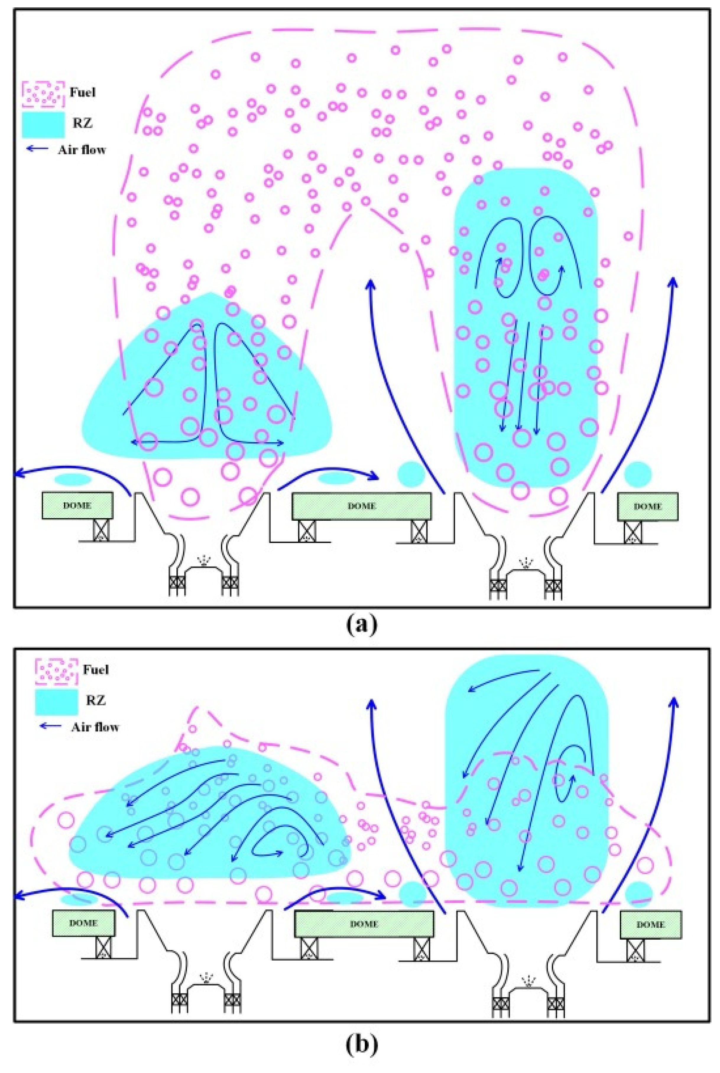
In summary, the fundamental divergence between annular and simplified single-dome combustors lies in their varying boundary conditions, as depicted in Figure 2. Annular combustors, experiencing mass transfer between adjacent domes, are characterized by aerodynamic boundaries. Intense FFI and JJI are often observed in such regions, which are considered the primary locations for NOx generation. Conversely, simplified model combustors encounter flame confinement due to side liner boundaries or solid boundaries. These model combustors often incorporate cooling air on the liner surface, giving rise to FWI and FCAI as well. Such interactions are predominantly confined to liner-adjacent zones, where flame chemistry is suppressed, leading to decreased local combustion efficiency, altered thermochemical states, and elevated emissions of CO and unburned hydrocarbons (UHC). The presence of FFI and JJI also serves as an aerodynamic boundary, as opposed to a solid wall boundary associated with FWI and FCAI.
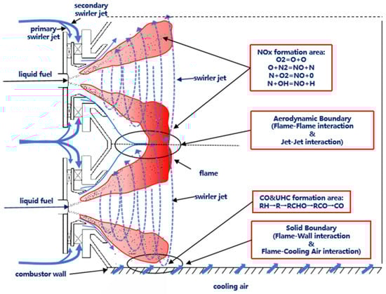
Figure 2.
Sketch of multiple physical fields with different boundary conditions.
Given the prior advances in the understanding of FWI and FCAI, they have been systematically studied in the abovementioned works. However, research on FFI and JJI started later partly due to the inherent experimental complexity, resulting in a lack of comprehensive introduction to the existing work. This article primarily focuses on the interactions among combustor sectors, with particular emphasis on the impact of FFI and JJI on the aerodynamic and thermodynamic processes within combustors.
2. Fundamental Characteristics of Swirl Flames
A gas turbine is a combustion engine that utilizes continuously flowing air as the working medium to convert the chemical energy of fuel into useful work. Depending on the application, gas turbines are generally classified into stationary gas turbines and aviation gas turbines. Stationary gas turbines are typically used for ship propulsion and power generation, with fuels ranging from gaseous (such as methane and propane) to liquid forms (like kerosene). In contrast, aero-engines, specifically engineered for aircraft, face stricter operational and performance requirements.
Maintaining combustion across a wide range of operating conditions is a crucial prerequisite for gas turbine combustors, particularly the ones in aero-engines. These chambers may operate under low temperatures and pressures, as well as fuel/air ratios that substantially deviate from the conventional flammability limits of hydrocarbon/air mixtures. Reliable ignition and sustained combustion are essential within highly turbulent airstreams, where velocities frequently exceed the normal burning velocities of the fuels employed. Furthermore, the flame must demonstrate robustness against various anomalous conditions that may occur during flight, including those induced by the ingestion of tropical rain or ice [1].
To ensure the stable and efficient operation of aero-engines, liquid fuels, pre-dominantly aviation kerosene, are employed. To achieve efficient and stable combustion of these liquid fuels within the combustor, it is imperative to establish a well-designed flow field, maintain an optimal fuel concentration distribution, and foster the development of a stable and efficient heat release zone.
The most prominent flow structure in a combustor is a stable low-velocity zone, which aids in flame stabilization. Swirling flow is utilized in gas turbines to establish this zone. Air introduced into the combustor via the swirler creates swirling flow, resulting in vortex breakdown. Under sufficiently strong swirl, airflow expands radially due to centrifugal force, generating a radial pressure gradient. Consequently, tangential velocity decreases, pressure gradually recovers along the central axis, and an axial adverse pressure gradient establishes along the streamwise axis, forming the primary recirculation zone (PRZ). Characterized by intense shear stress and high turbulence intensity, this process fosters momentum exchange between fuel droplets and air [24,25,26,27]. Swirling flow leads to a reduction in droplet size and enhances their uniform distribution. Figure 3 illustrates a typical swirling flow field within a combustor, highlighting essential flow characteristics, such as the PRZ downstream of the swirler, the shear layer encompassing the recirculation bubble, and the precessing vortex core (PVC) or helical mode that may occur under specific conditions. Radial expansion of swirling flow is a typical characteristic under strong swirling conditions, susceptible to the influence of solid liner confinement or adjacent swirl flows, thereby impacting flow characteristics and flame stabilization.
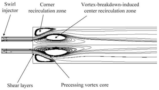
Figure 3.
Flow structures of a typical gas turbine combustor [24].
To ensure stable and efficient combustion across all operational conditions, the air entering the combustor is separated into multiple streams. In addition to the air intake at the dome, the remaining air passes through primary holes, dilution holes, and effusion cooling holes to enter the combustor. Within various zones of the combustor, these air flows are mixed with fuel and burned, through which key performance parameters, such as ignition, lean blow-off, combustion efficiency, emissions, and outlet temperature distribution, are determined.
Fuel atomization and its mixing with air constitute another pivotal process within the combustor. The combustion of aviation kerosene entails intricate high-temperature chemical reactions, governed by the complex interplay between turbulent flow and fuel concentration distribution. This interaction directly shapes the highly dynamic temperature field and combustion species field, both spatially and temporally. To facilitate complete combustion within constrained temporal and spatial boundaries, atomization is indispensable in maximizing the contact area between fuel spray and air. Hence, researchers engaged in the engineering development of combustors and fundamental investigations into swirl spray combustion consistently pursue higher evaporation rates and combustion efficiencies, thereby imposing stringent requirements on liquid fuel atomization and mixing.
Modern combustors often employ aerodynamically assisted atomization, leveraging both aerodynamic forces of the air and pressure differences in nozzle injection to achieve good atomization and mixing across a wide range of operating conditions. Plain orifice nozzles and pressure swirl nozzles eject fuel spray and form high-speed jets. Figure 4 shows an example of a plain orifice nozzle [28]. These jets rapidly disintegrate down-stream, forming sprays with a defined atomization cone angle. Subsequently, under the influence of swirling aerodynamic forces, the fuel undergoes further atomization into finer droplets, marking the completion of secondary atomization. During this atomization process, fuel droplets also show radial movement due to the centrifugal action of swirling air, ultimately facilitating mass and momentum exchange with adjacent domes. By precisely controlling the fuel injection positions and swirling air parameters during atomization and mixing, a satisfactory fuel–air matching scheme can be achieved, enabling rapid fuel evaporation and thorough mixing with air, thereby enhancing combustion efficiency and reducing combustion pollutants.
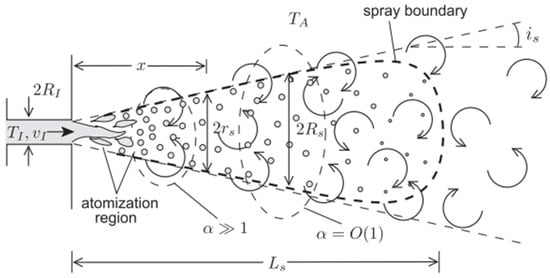
Figure 4.
A schematic view of a vaporizing spray generated by a plain orifice atomizer [28].
The processes of atomization, vaporization, and mixing of liquid fuel play pivotal roles in determining the performance of combustors. The realistic areo-engine operating conditions, involving elevated temperatures and pressures, further complicate these processes beyond the aforementioned descriptions. By manipulating how fuel and air are mixed, various combustion technologies can be implemented to meet the demands for high temperature rise and low emissions. Notable methods include lean premixed prevaporized combustion (LPP) [29,30,31], rich burn–quench–lean burn (RQL) [32,33], and lean direct injection (LDI) [34,35]. They regulate the combustion reaction process across different zones of the combustion chamber through adjustments in the air partitioning and local fuel concentration, ultimately resulting in distinct flame stabilization patterns tailored to specific combustor characteristics.
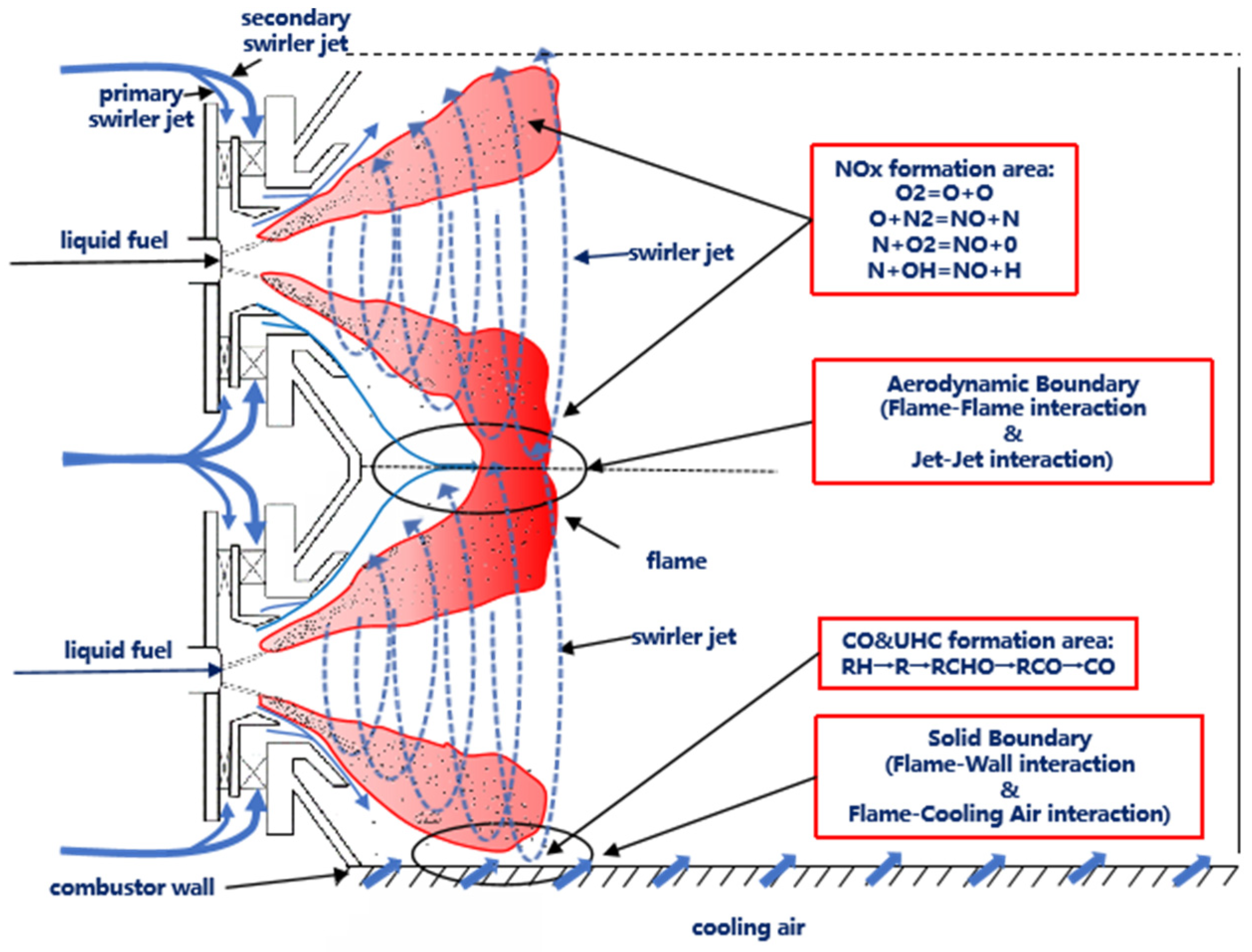
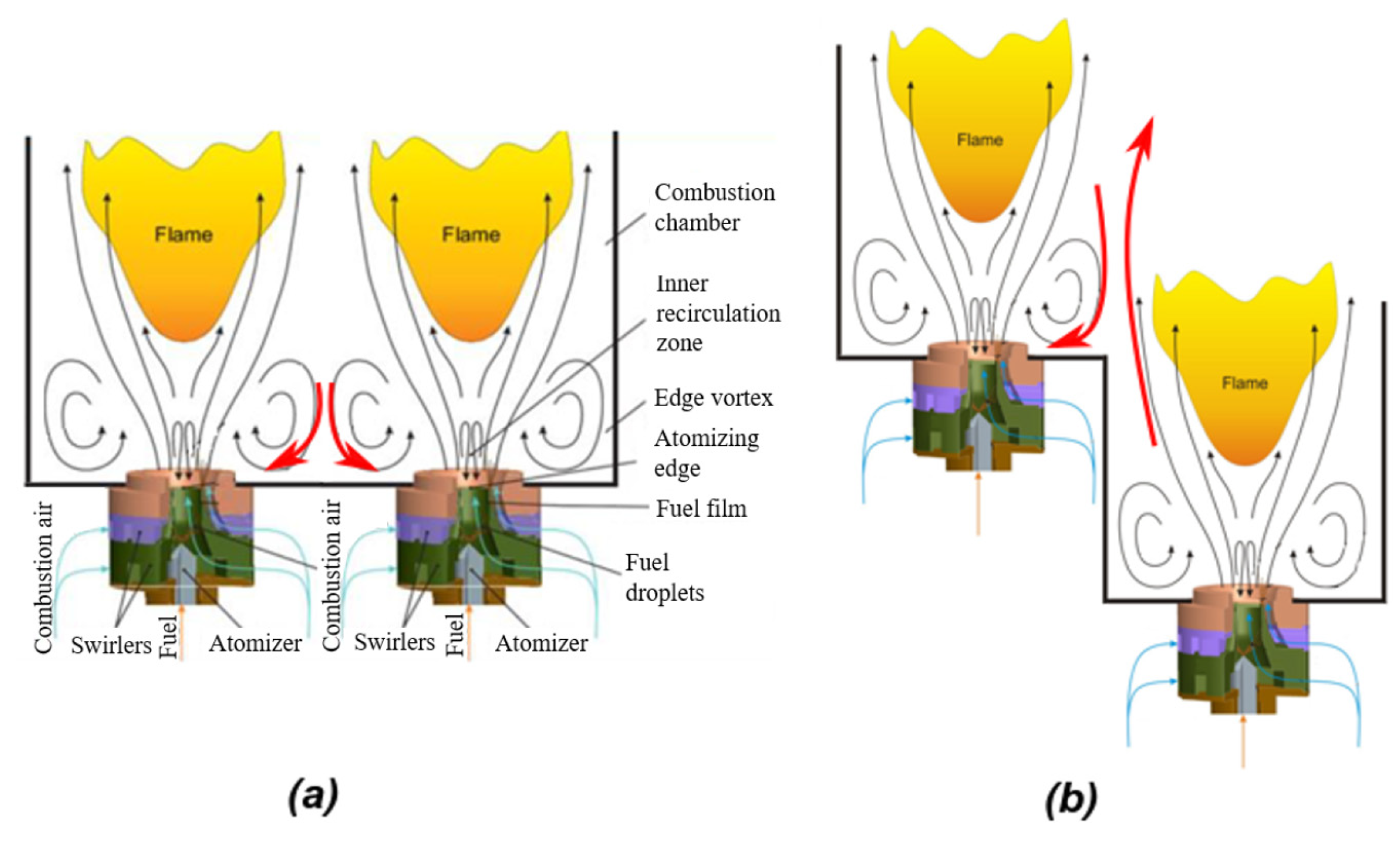
Figure 5 delineates multiple physical processes within a typical combustor configuration featuring a swirling dome integrated with primary and dilution holes for extra jet injection. A portion of the air, after passing through the swirl dome, forms a rotating jet that interacts with the fuel spray cone issued from the nozzle, facilitating initial and secondary atomization processes. This interaction results in the downstream formation of a fuel–air mixture. Subsequently, it also contributes to the creation of a PRZ near the combustor center, along with a corner recirculation zone (CRZ) between the swirling air and the solid liner wall. The recirculation zones facilitate the upstream transport of partially burned products to ignite fresh fuel–air mixtures. The flames are primarily located in the shear layer between these recirculation zones. Meanwhile, another portion of air flows through the annulus between the liner and outer casing, entering the combustor via primary, dilution holes, and effusion cooling holes. The jet from the primary holes disrupts the PRZ. Upstream of the primary holes, swirling flow is dominant, where fuel and air mix and burn intensely, contributing substantially to heat release. Beyond the primary holes, swirling effects gradually diminish, and the flow from these holes further integrates with unburned fuel and combustion products from the dome, completing most chemical reactions before reaching the dilution holes. The jet from the dilution holes blends with the hot gas to regulate the temperature distribution at the combustor outlet, designed to fulfill an important performance parameter. Generally, the region upstream the primary holes is fuel-rich, whereas the downstream area is fuel-lean; both serve as primary sources of NOx formation. Due to effusion cooling adjacent to the liner, the flame quenches, leading to potential problems associated with combustion efficiency and pollutant formation.
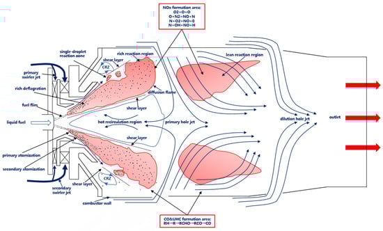
Figure 5.
Flow structures, spray pattern, and flame within a typical swirl combustor.
3. Combustor Characteristics Under FFI and JJI
The experimental apparatus for a single-dome combustor is often used due to its simplicity and ease of parameter manipulation. Nevertheless, it fails to capture many features that are observed in multi-dome combustors [36,37]. Previous research has clearly highlighted significant aerodynamic disparities between full-annular and single-sector combustors, particularly for example the jet flowing along the dome plane in single-dome combustors and the prevailing free swirling jets in annular combustors [37].
Within multi-dome combustors, the distributions of physical quantities of adjacent domes typically display periodic variations. This arises from the progressive expansion of the airflow from the swirler outlet, leading to interactions between neighboring domes. Such interactions result in significant mass and energy exchanges, accompanied by coupled turbulence and chemistry. They ultimately exert profound influence on the flow, spray, combustion, and overall performance of the annular combustor.
3.1. Flow Characteristics Under FFI and JJI
Jeng et al. have conducted a series of studies on the cold flow characteristics within single-dome, triple-dome, and quintuple-dome linearly-arranged combustors, using several techniques, including laser Doppler velocimetry (LDV) [38,39,40], numerical simulations [41], and phase Doppler particle analyzer (PDPA) [42]. Their initial experimental investigation of a single-dome combustor devoid of sidewalls revealed that solid wall confinement strongly impacted the flow characteristics of the combustor [38,39,40]. With the absence of sidewalls, the swirling flow was ejected almost entirely along the dome plane, yielding an unbounded PRZ. Conversely under sidewall constraints, the size of the PRZ correlated directly with the distance from the sidewall. The compressive force exerted by the sidewall prompted rapid momentum exchange between the two counter-rotating flows generated by the two-stage radial swirler, causing the PRZ of the second stage to dominate the flow at the swirler outlet. Notably, the swirling jet exhibited a reduced expansion angle relative to the swirler axis and shifted downstream due to sidewall compression, highlighting the restrictive influence of sidewalls on flow patterns.
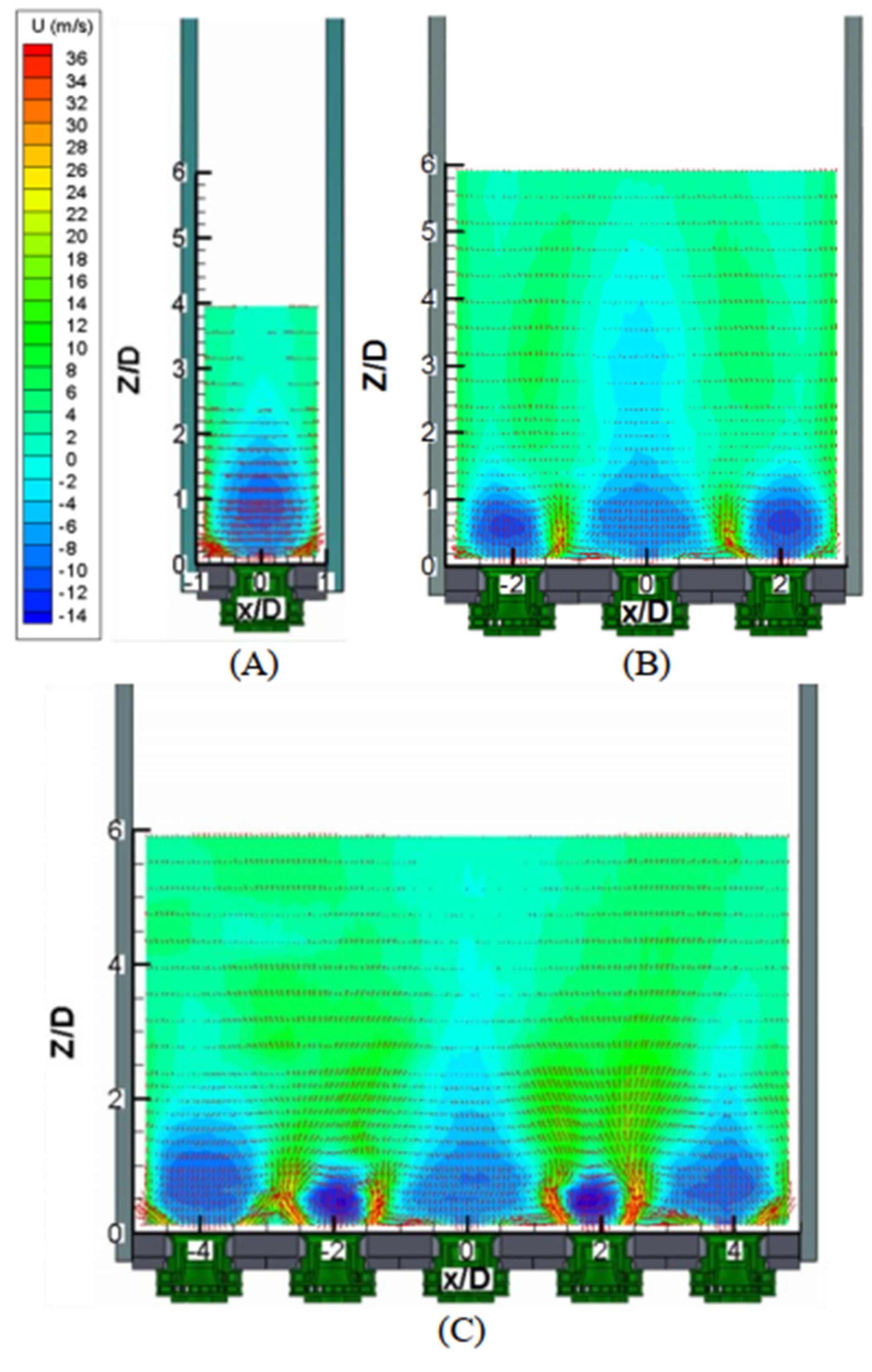
Subsequent research on multi-dome combustors with sidewalls by Jeng et al. [38,39,40,41,42] uncovered that swirling flow interactions among adjacent domes introduced complexity in the flow field. Specifically, in triple-dome combustors, the recirculation zone of the middle dome was relatively weak, whereas those on both sides were more pronounced. In quintuple-dome combustors, the recirculation zones followed a sequential “weak–strong–weak–strong–weak” pattern. Additionally, the intensity of interaction among the domes was elevated in the five-swirler configuration compared to the three-swirler configuration, as shown in Figure 6.

Figure 6.
Axial velocity contours overlaid with in-plane velocity vectors: (A) single-swirler configuration, (B) 3-swirler configuration, and (C) 5-swirler configuration [40].
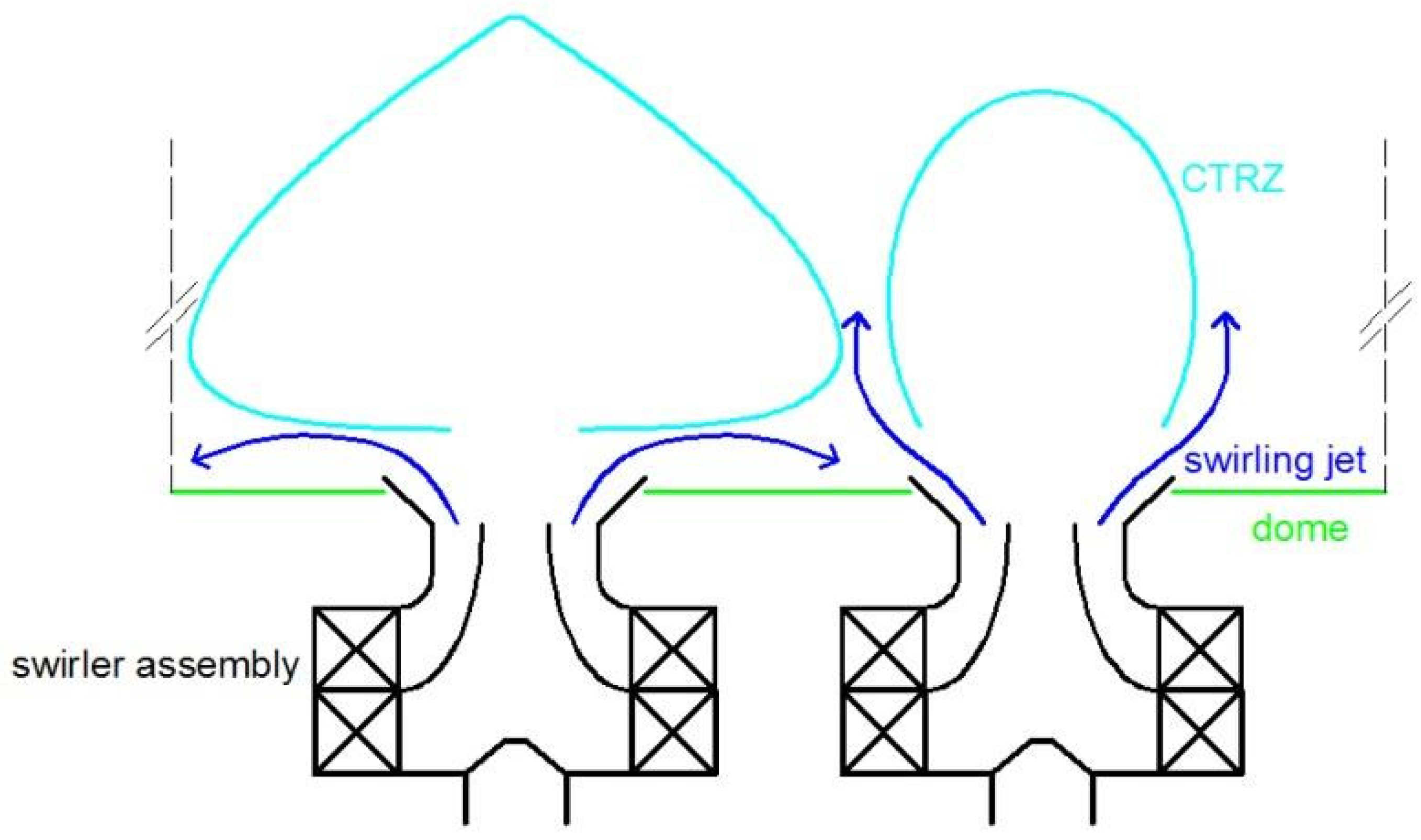
In References [43,44,45], the alternating flow pattern between adjacent domes was also noted. Jeng et al. [38] offered a cogent explanation for this phenomenon, as shown in Figure 7, where PRZ is known as the central toroidal recirculation zone (CTRZ). There were two distinct patterns of swirling flow in a single-dome combustor, i.e., either one flowing along the dome plane with a large PRZ, or one impinging on the sidewall with a compact PRZ; confinement could facilitate a transition from the former to the latter [38,39,40]. In multi-dome combustors, the central dome, due to its maximal distance from the sidewalls, demonstrated a stronger propensity to adopt the “dome-attached swirling flow” with an expanded PRZ compared to the other four swirlers. When one injector featured flow along the dome plane, it would supply sufficient air to adjacent domes, prompting them to adopt the free swirling jet pattern with a compact PRZ. This explanation rationalized the alternating occurrence of the two flow structures in multi-dome combustors.

Figure 7.
Sketch of an alternating PRZ distribution [38].
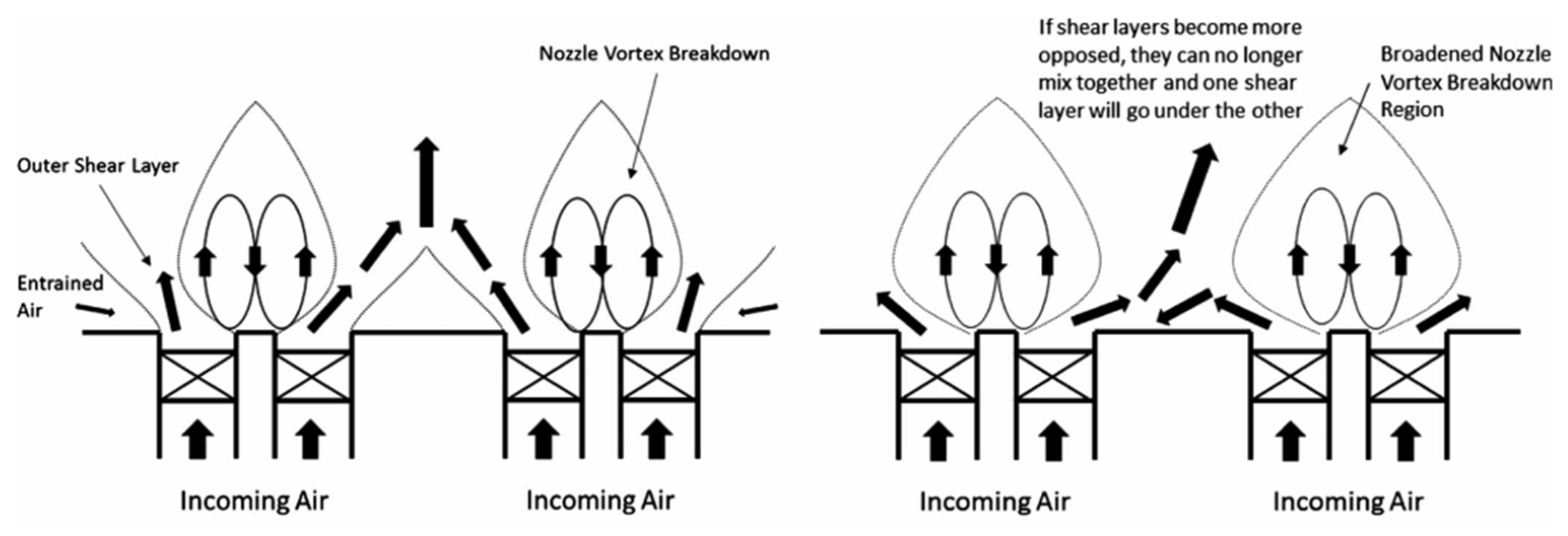
Dolan et al. [44] further investigated the impacts of the injector sleeve expansion angle and swirl number in the linearly arranged multiple-dome combustors on such an alternating flow pattern. They observed that as these two parameters increased within specific ranges, the shear layer moved closer to the dome plane. This enhanced dome–dome interaction and led to the disappearance of CRZ and exhibited similar flow pattern. By extending the insights of Jeng et al. [38], Dolan et al. proposed a hypothesis. If the design, flow, or combustion characteristics of the combustor cause the swirling jets of two neighboring domes to flow in sufficiently opposite directions, the two jets would no longer mix and flow downstream as one combined axial jet. In fact, if one swirling jet goes radially and the other goes axially downstream, distinct flow features can be observed from these two nozzles.
Dolan et al. also invoked the well-established framework of turbulent planar jet theory to elucidate this phenomenon. Typically, two opposing low-Reynolds-number jets would create a stable and symmetric system upon collision. With a smaller angle, the two jets near the central plane can coalesce into a single jet in their combined flow direction. However, with a higher Reynolds number or a larger angle of collision, the system may become hydrodynamically unstable, resulting in a variety of steady states or periodic solutions. Of particular note is the prevalent periodic solution known as “deflected jet oscillation”, where the two jets are alternately deflected in opposing directions and periodically switch directions. In this scenario, one jet is suppressed to be underneath the other. This analogy provides a theoretical explanation for the alternating flow patterns observed within multi-dome combustors.
3.2. Spray Characteristics Under FFI and JJI
Jeng et al. [42] subsequently conducted spray measurements in a quintuple-dome combustor, where similar alternating pattern in the spray field was also observed, as shown in Figure 8. Extending the work of Refs. [38,42], Gao et al. [46] analyzed the influence of dome–dome interactions on the spray field. At low flow velocities, the interaction between adjacent domes was weak, leading to smaller recirculation zones and the formation of two independent yet similar spray cones. These spray cones occupied fuel-rich reaction zones, extensively distributing downstream of the domes. As the bulk velocity increased, the interaction between adjacent domes intensified, causing the merging of spray cones. Stronger recirculation compressed the spray into a broader and shorter configuration, facilitating spray merging. The entrainment effect of the recirculation zone on droplets intensified. The consequent alternating pattern in the spray field was similar to that in the flow field. Gao et al. also reaffirmed that the “deflected jets” between adjacent domes were the underlying cause of the alternating flow pattern.
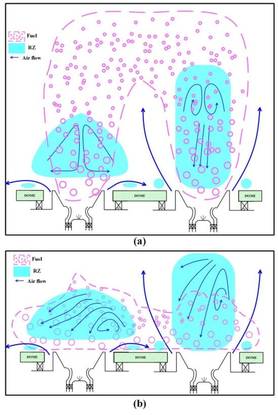
Figure 8.
Sketch of the spray pattern, where the pink circles denote the fuel droplets: (a) rich dispersed spray pattern (low bulk velocity), and (b) lean merged spray pattern (high bulk velocity) [46].
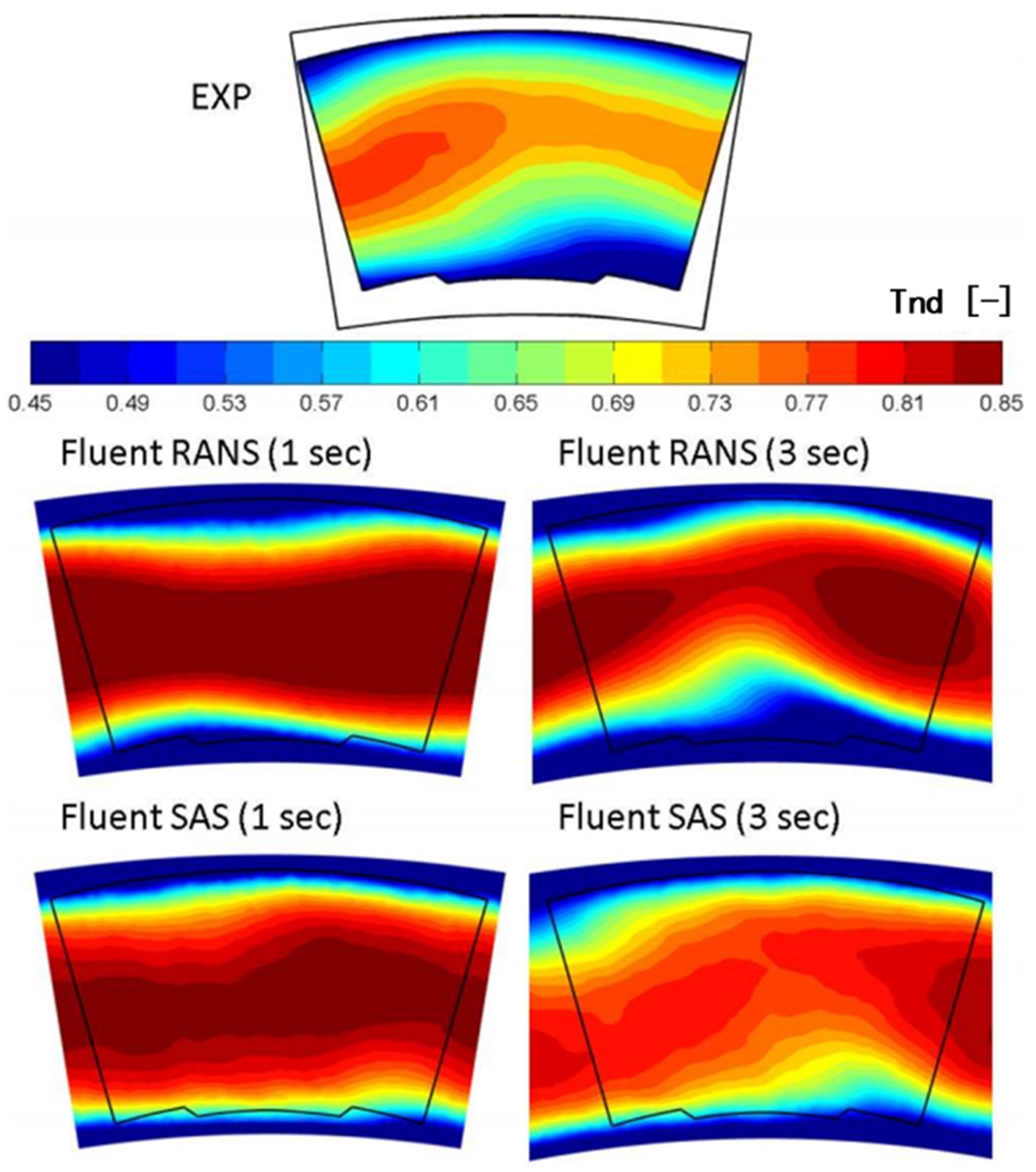
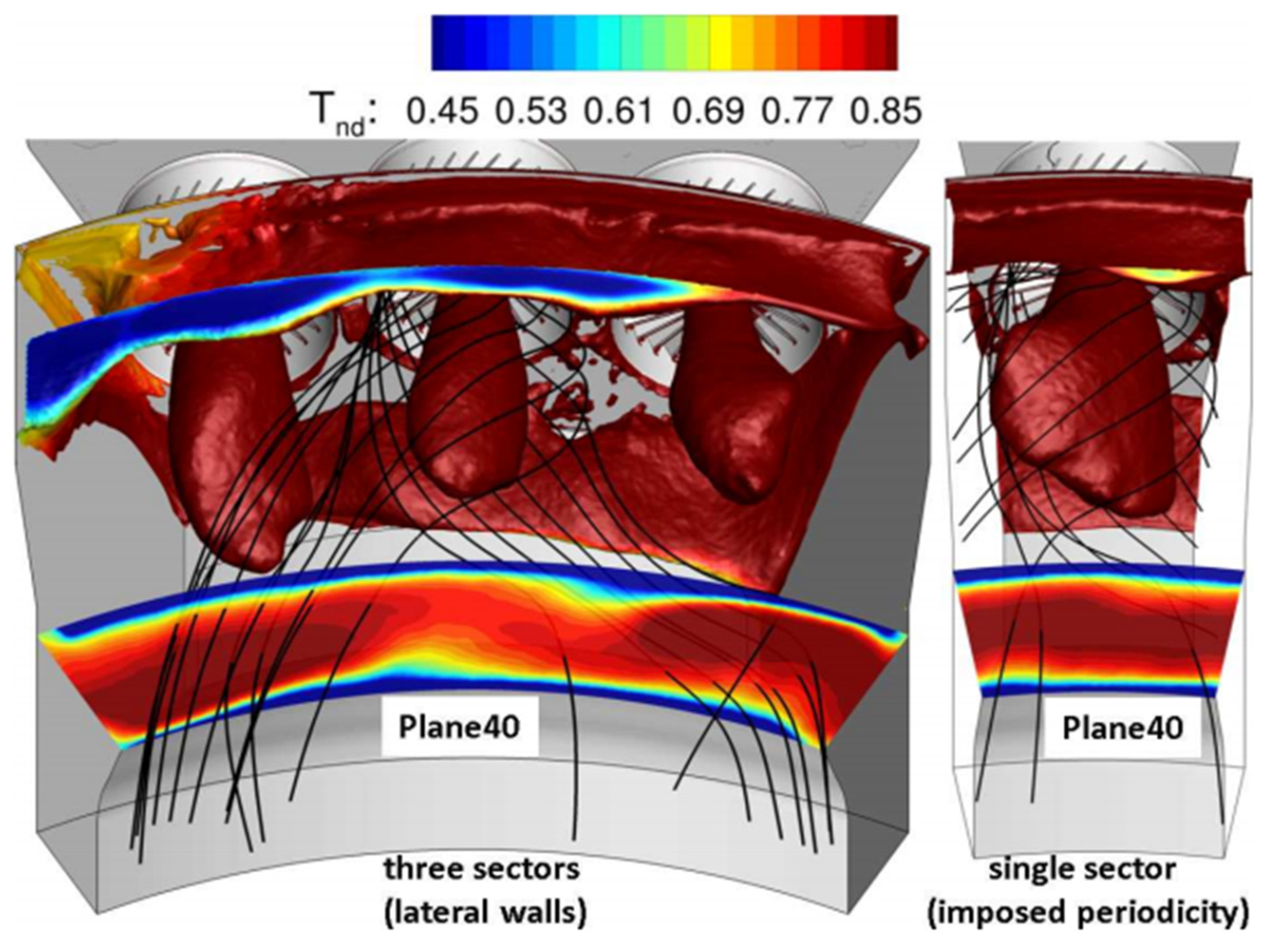
The occurrence of the deflected jet has been noted as a prominent feature within multi-dome combustors in other studies as well. For example, Andreini et al. [47] investigated the outlet temperature distribution of a triple-dome combustor using numerical simulations and discerned a notable shift in the temperature distribution toward adjacent domes at the combustor outlet, as shown in Figure 9 and Figure 10. Intriguingly, the computed results exhibited a closer alignment with experimental data when compared to those obtained from a single-dome combustor. The streamline plot presented in Figure 10 illustrates how the deflection of jets toward adjacent domes led to differences in the flow field between the triple-dome and single-dome configurations. This observation also gained further support from the subsequent findings reported in Refs. [48,49], as shown in Figure 11.
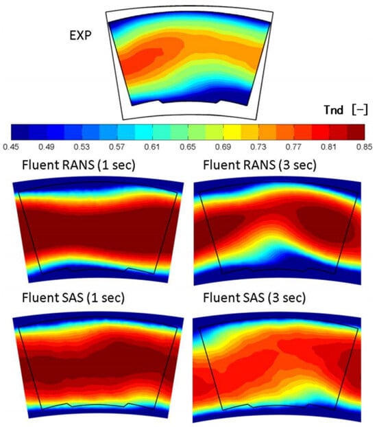
Figure 9.
Temperature: effect of periodicity [47].

Figure 10.
Visualizations of recirculation zones and temperature [47].
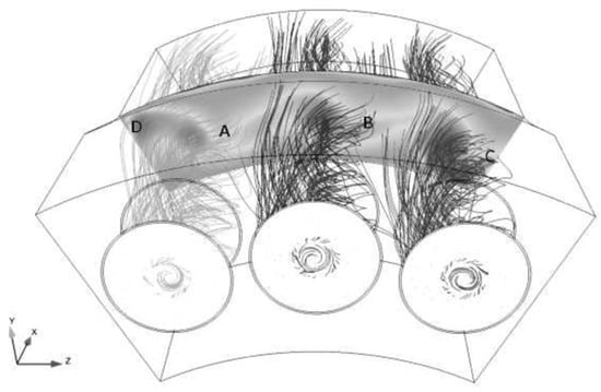
Figure 11.
Streamlines emitted from each swirler in the trisector [48]. Letters A–D indicate the hot spots in the combustor.
3.3. Flame Structures Under FFI and JJI
The interaction between combustor domes also exerts a profound influence on the flame structure [36,37,49,50,51,52]. Under certain conditions, periodicity in flame appearance may occur as well [38,40,42,45,46,51]. Szedlmayer [36] and Fanaca et al. [37] noted considerable variations in flame characteristics between annular and single-dome combustors. Kariuki [50] demonstrated that alterations in swirl intensity among adjacent domes modified the macroscopic flame shapes during the blowout process. Furthermore, Durox [51] found that FFI and JJI could result in adjacent flames adopting completely opposing shapes, with these alternating patterns switching periodically at the same frequency. Dolan et al. [52] emphasized that interactions among domes could induce asymmetry in both the flow and the flame.
In Ref. [46], a close correlation was observed between fuel spray distribution and flame morphology, with a notable decrease in both sizes as the flow velocity augmented. Specifically, at lower flow velocities, the relatively weak PRZ led to a dispersed downstream fuel distribution, subsequently weakening the entrainment and anchoring influence of the swirling jet on spray and flame. Conversely, at higher velocities, the enhanced recirculation zone resulted in an analogous distribution of fuel and flame to the shape of PRZ. Furthermore, the flame structure delineated in Ref. [42] exhibited a “wide–narrow–wide” feature, as also reported in Refs. [38,40,46]. This phenomenon underscores the pivotal role of the flow field in shaping the fuel distribution and flame structure, reinforcing the notion of strong interdependence among the flow structure, atomization, and combustion in swirl spray flames.
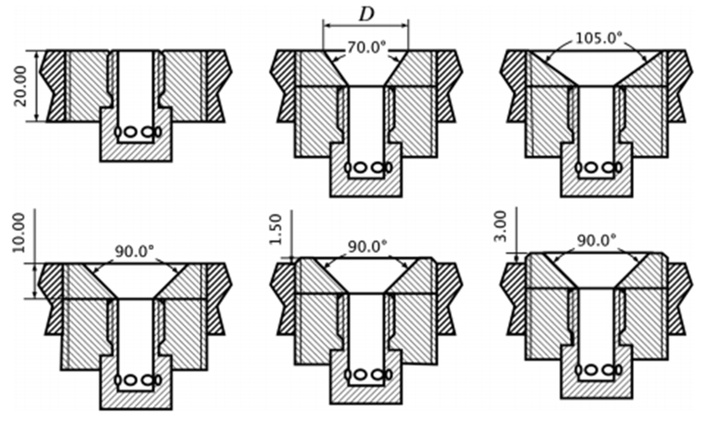
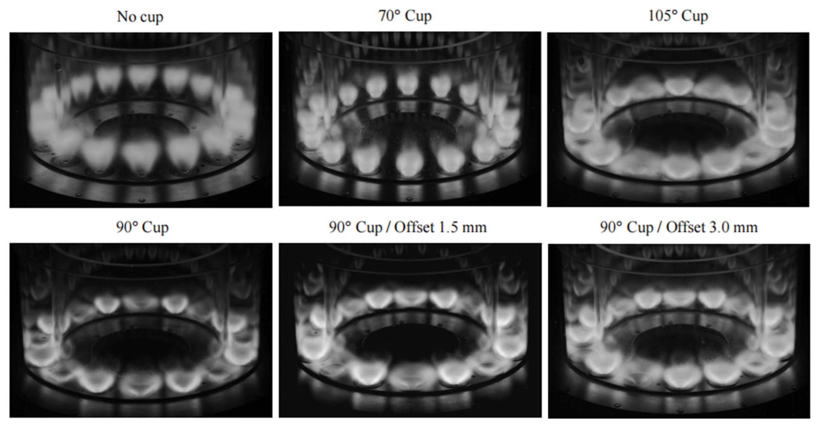
A common structural feature in the works of Kao et al. [38,40,42], Gao et al. [46], and Durox et al. [51] is the flare exit, as shown in Figure 12. This structure promotes the swirling jet to flow toward the dome plane, undergoing a notable directional shift. On the other hand, the study documented in Ref. [51], considered both injectors with variable flaring angle and injectors without a flared exit. When the flare exit cup is absent, a remarkable similarity appears in the flame structure across each dome, as illustrated in Figure 13. These findings lend additional support to the aforementioned theoretical framework put forward by Dolan [44].

Figure 12.
The different injectors with and without a flare exit [51].
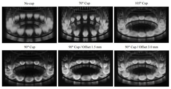
Figure 13.
Typical flame shapes obtained for the different injector geometries [51].
Another study conducted by Dolan et al. [45] further demonstrated different flame structures, as visualized in Figure 14. In the case of a propane–air flame (right panel), one of the domes had a flame stabilized around a radially broader recirculation bubble. When methane was utilized instead (left panel), the asymmetry between the two domes disappeared. This asymmetry arose due to propane’s higher density compared to methane, resulting in reduced momentum and thus lower flow velocity at the same equivalence ratio. Consequently, the propane was transported further radially outward. The greater centrifugal force exerted on the propane jet as well as its higher adiabatic flame temperature, contributed to a larger and broader recirculation zone for the propane–air flames, ultimately yielding a swirling jet flowing closer to the dome wall.

Figure 14.
Flame shapes caused by different shear layer flow directions between two neighboring domes (left: methane, right: propane) [45].
In summary, the design of combustor domes may be subject to deflected jet instability, leading to the displacement of one neighboring jet beneath the other. This phenomenon eventually results in alternating patterns in the flow, spray, and flame, which are commonly seen in multi-dome combustors.
3.4. Combustor Performance Under FFI and JJI
The interactions among domes may exert significant influence on the overall performance of the combustor. In this section, we focus on three crucial aspects: blowout, emissions, and ignition.
3.4.1. Blowout Performance
Dolan et al. [53] observed that reducing the spacing between combustor domes resulted in an augmentation of the lean blowout (LBO) fuel–air ratio (FAR). This phenomenon was attributed to intensified dome–dome interactions, which subsequently increased the axial velocity and compromised flame stabilization within the shear layer. Kwong et al. [54] conducted experimental investigations in a five-swirler linearly arranged combustor to quantify the variations in LBO FAR arising from the interactions among nozzles, emphasizing the significant impact of flow field alterations induced by changes in nozzle spacing on LBO characteristics. Jella et al. [55] studied several burners using large eddy simulations (LES). By analyzing the mechanisms underpinning FFI on LBO resulting from varying dome spacing, they found that the five-swirler combustor, characterized by the smallest spacing, exhibited inferior blow-out performance due to the shortest residence time within the recirculation zone. In contrast, the two-swirler combustor demonstrated the lowest LBO FAR, benefiting from an optimal dome spacing that enhanced transport effects and facilitated flame stabilization by igniting the reactants by high-temperature products. This finding was further elucidated through a comparative assessment of swirling jet strain rates, flame curvature, residence time within the recirculation zone, and transport properties across the nozzles.
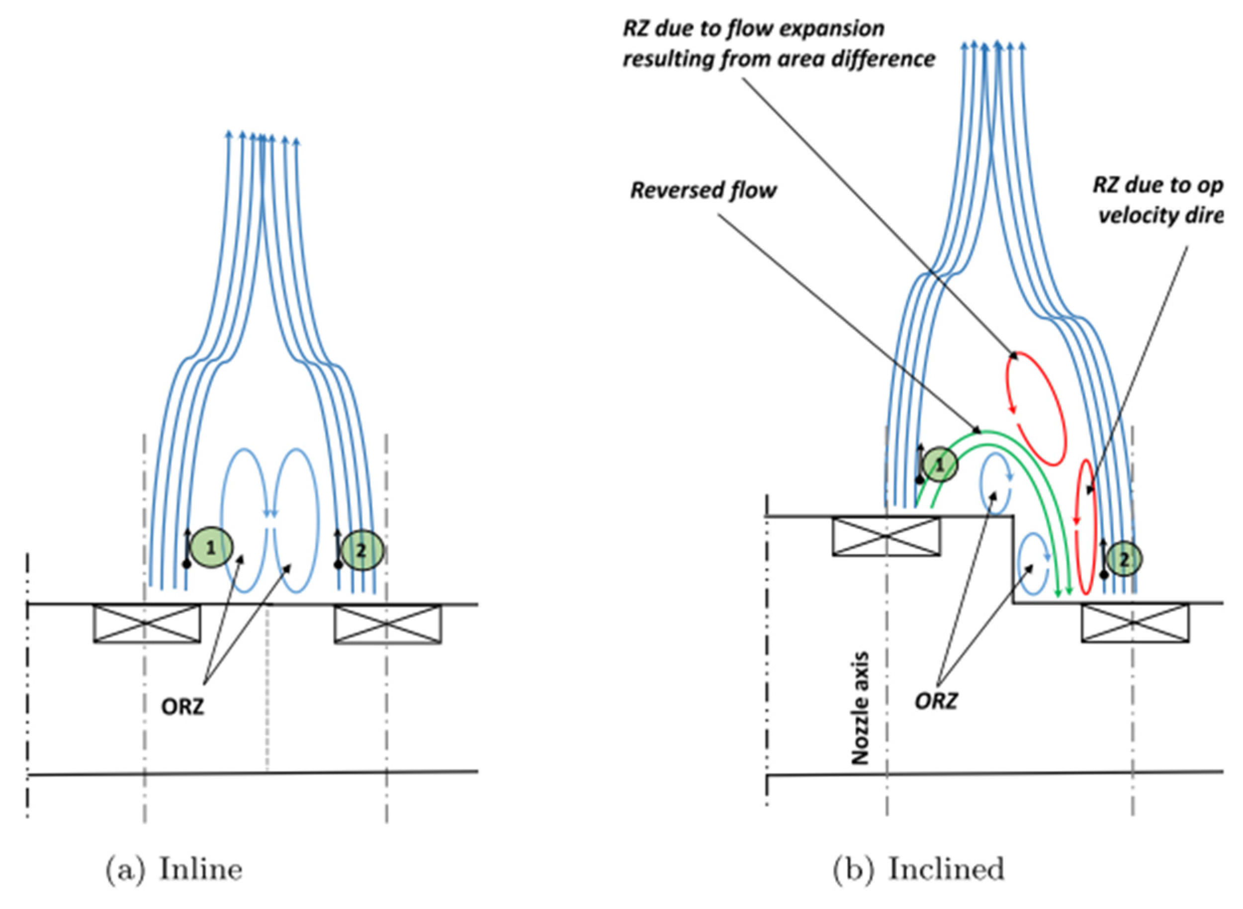
Shamma et al. [56] embarked on an alteration of the dome arrangements within the combustor, shifting from the conventional linear alignment to an inclined configuration, as shown in Figure 15. Contrary to the observations noted in Ref. [53], aerodynamic stability within the combustor did not decline despite intensified dome–dome interactions. This anomaly could be ascribed to the transport of combustion products from one dome to the flame root and outer recirculation zone (ORZ) of adjacent domes in the inclined setup, thereby substantially enhancing flame stability. Subsequent investigations [57] revealed that, driven by pressure gradients between a low-pressure, high-velocity free jet and a high-pressure, low-velocity confined jet, a portion of gases migrated from point 1 to point 2, as illustrated in Figure 16. This migration effectively isolated the ORZ, mitigating its effects on flame stabilization. Furthermore, due to flow expansion and direction changes, two additional smaller recirculation zones (highlighted by red arrows in Figure 16) emerged within the combustor, compensating for the ORZ and further bolstering flame stabilization. The study also employed spray Mie scattering and OH* chemiluminescence to elucidate the impact of fuel droplet evaporation duration on flame stabilization near the flame root under varying conditions. The mechanisms underlying flame stabilization were influenced by a spectrum of parameters, including ORZ dimension, inlet temperature, and secondary vortices induced by pressure differences adjacent to the wall.

Figure 15.
Principle of flame interactions from different configurations [56]: (a) the inline configuration and (b) the inclined configuration.
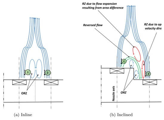
Figure 16.
The effect of the stepped wall in the staggered case on the recirculated flow between the adjacent burners [57].
3.4.2. Emissions Performance
The emissions profiles of combustors are intrinsically tied to the interactions occurring among the domes. Cho et al. [58] documented an increase in the emission index of NOx (EINOx) in a multi-dome combustor relative to a single-dome configuration. Their research emphasized the profound impact of flow and flame dynamics on NOx emissions, highlighting a significant dependence on the spacing between domes. Similarly, Dolan et al. [52] noticed comparable trends and concluded that variations in flame distribution played a pivotal role in regulating NOx emissions. Shamma et al. [57] introduced alterations to the combustor dome arrangement, aiming to alter the interaction patterns among domes. This approach resulted in a modest yet notable improvement in the control of NOx emissions.
Kwak et al. [59] employed OH* chemiluminescence and particle image velocimetry (PIV) to investigate the correlation between FFI and emissions performance. Their findings revealed that, while FFI exerted a minor influence on CO emissions, it had a pronounced effect on NOx emissions, as evident in Figure 17 and Figure 18. In the primary flow collision zone of dual nozzles, flame merging was observed, featuring localized high velocity—a phenomenon absent in the single-dome combustor. This high-velocity flow negatively affected flame stabilization, leading to an elevated LBO FAR in the dual-nozzle combustor. Detailed measurements and reconstructive analyses of flame shape and temperature distribution further unveiled larger high-temperature zones in the dual-nozzle combustor due to FFI, ultimately contributing to a substantial augmentation in NOx emissions.
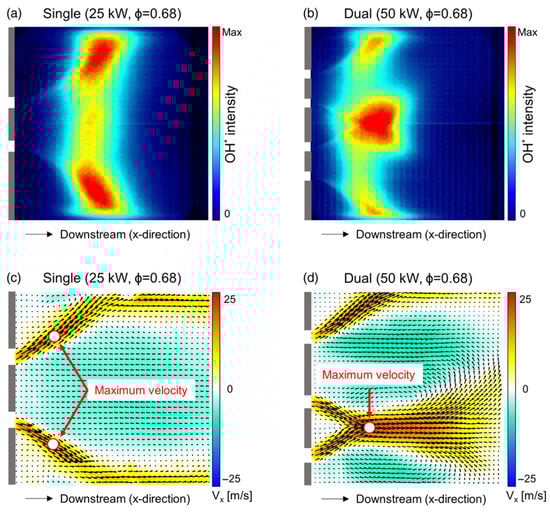
Figure 17.
Average OH* chemiluminescence images and flow fields [59].
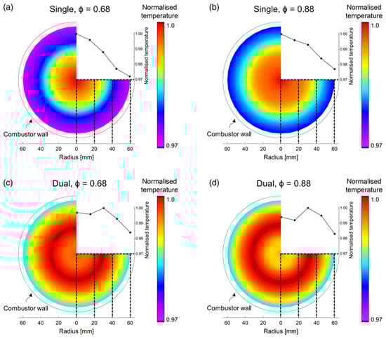
Figure 18.
Reconstructed 2D temperature distribution [59].
3.4.3. Ignition Performance
The ignition sequence within multi-dome combustors typically unfolds through four distinct stages [46]: the initial formation of a self-sustaining flame kernel, the subsequent propagation of this kernel within a single dome, the stabilization of a single-dome flame, and finally, the light-round process, which is defined as the process in which the flame initiated by an ignition spark propagates from dome to dome in an annular combustor, eventually leading to stable combustion [60]. The ignition sequence in multi-dome combustors is generally complex due to the light-round process, compared to the single-dome combustors. Consequently, the majority of the existing literature on FFJ in multi-dome combustors has centered on the light-round process. For example, Santiago et al. [61,62] conducted an investigation into the ignition performance of an arcuately arranged multi-dome combustor burning liquid n-heptane, elucidating the mechanisms underlying flame propagation within such systems.
The light-round process in annular combustors has been studied extensively by researchers from various institutions across the world, notably including the EM2C Laboratory in France [63,64,65,66,67,68,69,70], the University of Cambridge in the UK [71,72,73,74,75], Zhejiang University in China [76,77,78], and the Institute of Engineering Thermophysics of the Chinese Academy of Sciences [46,79,80]. The methodologies and operating conditions associated with these studies are summarized in Table 1.

Table 1.
Summary of studies on ignition in annular combustors.
The focus of these investigations has primarily been on elucidating the mechanisms controlling the light-round process in multi-dome combustors during the ignition phase. However, a detailed discussion on the subsequent FFI or JJI between combustor domes has been somewhat limited in these studies; therefore, we will not expand further here.
It is noteworthy that the existing research on FFI and JJI has primarily revolved around fundamental research utilizing gaseous fuels. Although swirl spray flames have been incorporated in studies from Refs. [42,46,56,57,61,62,65,66,67,68], the experimental conditions and combustor designs presented therein exhibit significant deviations from those typically observed in aero-engines. To date, no scholarly endeavor has been identified that comprehensively examines FFI and JJI in swirl spray flames with engine-relevant geometry and conditions.
4. Conclusions
The constraints imposed by differing boundary conditions on single-dome model combustors lead to an inadequate representation of the crucial features of annular combustors, including flame–flame interaction (FFI) and jet-–et interaction (JJI). Consequently, the design outcomes derived from these models may not accurately mirror the complex physical and chemical characteristics of actual combustors. In contrast, annular combustors exhibit FFI and JJI, causing the flow exiting the swirler to deflect toward the neighboring dome, resulting in one jet being displaced beneath another. This gives rise to an alternating pattern within the flow field, which is echoed in the spray field and flame structure. Additionally, in the zone of interaction between adjacent domes, a superposition of mass and energy transfer is observed, manifested as heightened flow velocity and temperature. This typically leads to deteriorated flame stabilization, elevated ignition/blowout FAR, and higher NOx emissions due to prolonged flame residence times. In essence, dome–dome interactions primarily involve the dynamic exchange of energy and mass, profoundly influencing the overall characteristics of the combustor.
This review article has attempted to systematically delineate the characteristics of multi-dome combustors, with an emphasis on FFI and JJI. It is also pointed out that, currently, there is a lack of research comparing single-dome and multi-dome combustors under engine-relevant conditions. As far as we know, some 41researchers, including us, have recently started explorations on the multi-dome aviation combustors at elevated pressures and temperatures using optical diagnostics. These data are expected to provide stronger references for aero-engine designers.
Author Contributions
Conceptualization, W.W. and X.X.; methodology, Q.A. and X.H.; writing—original draft preparation, W.W. and Q.A.; writing—review and editing, W.W. and Q.A.; supervision, S.Y. All authors have read and agreed to the published version of the manuscript.
Funding
This research was funded by the National Natural Science Foundation of China (Nos. 92041001 and 5220061469).
Conflicts of Interest
The authors declare no conflicts of interest.
Abbreviations
The following abbreviations are used in this manuscript:
| FFI | Flame–flame interaction |
| JJI | Jet–jet interaction |
| FWI | Flame–wall interaction |
| FCAI | Flame–cooling air interaction |
| PRZ | Primary recirculation zone |
| PVC | Precessing vortex core |
| LPP | Lean premixed prevaporized combustion |
| RQL | Rich burn–quench–lean burn |
| LDI | Lean direct injection |
| CRZ | Corner recirculation zone |
| LDV | Laser Doppler velocimetry |
| PDPA | Phase Doppler particle analyzer |
| CTRZ | Central toroidal recirculation one |
| LBO | Lean blowout |
| FAR | Fuel–air ratio |
| LES | Large eddy simulation |
| EINOx | Emission index of NOx |
References
- Lefebvre, A.H.; Ballal, D.R. Gas Turbine Combustion: Alternative Fuels and Emissions, 3rd ed.; CRC Press: Boca Raton, FL, USA, 2010. [Google Scholar]
- Poinsot, T.; Veynante, D. Theoretical and Numerical Combustion; RT Edwards: Sydney, Australia, 2005. [Google Scholar]
- Nogenmyr, K.J.; Cao, H.J.; Chan, C.K.; Cheng, R.K. Effects of confinement on premixed turbulent swirling flame using large eddy simulation. Combust. Theory Model. 2013, 17, 1003–1019. [Google Scholar] [CrossRef]
- Mercier, R.; Guiberti, T.F.; Chatelier, A.; Durox, D.; Gicquel, O.; Darabiha, N.; Schuller, T.; Fiorina, B. Experimental and numerical investigation of the influence of thermal boundary conditions on premixed swirling flame stabilization. Combust. Flame 2016, 171, 42–58. [Google Scholar] [CrossRef]
- Bénard, P.; Lartigue, G.; Moureau, V.; Mercier, R. Large-eddy simulation of the lean-premixed PRECCINSTA burner with wall heat loss. Proc. Combust. Inst. 2019, 37, 5233–5243. [Google Scholar] [CrossRef]
- Andreini, A.; Becchi, R.; Facchini, B.; Mazzei, L.; Picchi, A.; Vitale, I.; Tolpadi, A. Experimental and numerical investigation of the mutual interaction between liner film cooling and combustor swirl flow. In Proceedings of the ASME Turbo Expo 2017: Turbomachinery Technical Conference and Exposition, Charlotte, NC, USA, 26–30 June 2017. [Google Scholar]
- Hermann, J.; Greifenstein, M.; Boehm, B.; Dreizler, A. Experimental investigation of global combustion characteristics in an effusion cooled single sector model gas turbine combustor. Flow Turbul. Combust. 2019, 102, 1025–1052. [Google Scholar] [CrossRef]
- Dreizler, A.; Böhm, B. Advanced laser diagnostics for an improved understanding of premixed flame-wall interactions. Proc. Combust. Inst. 2015, 35, 37–64. [Google Scholar] [CrossRef]
- Bohlin, A.; Mann, M.; Patterson, B.D.; Dreizler, A.; Kliewer, C.J. Development of two-beam femtosecond/picosecond one-dimensional rotational coherent anti-Stokes Raman spectroscopy: Time-resolved probing of flame wall interactions. Proc. Combust. Inst. 2015, 35, 3723–3730. [Google Scholar] [CrossRef]
- Bohlin, A.; Jainski, C.; Patterson, B.D.; Dreizler, A.; Kliewer, C.J. Multiparameter spatio-thermochemical probing of flame–wall interactions advanced with coherent Raman imaging. Proc. Combust. Inst. 2017, 36, 4557–4564. [Google Scholar] [CrossRef]
- Kosaka, H.; Zentgraf, F.; Scholtissek, A.; Bischoff, L.; Häber, T.; Suntz, R.; Albert, B.; Hasse, C.; Dreizler, A. Wall heat fluxes and CO formation/oxidation during laminar and turbulent side-wall quenching of methane and DME flames. Int. J. Heat Fluid Flow 2018, 70, 181–192. [Google Scholar] [CrossRef]
- Jainski, C.; Rißmann, M.; Böhm, B.; Janicka, J.; Dreizler, A. Sidewall quenching of atmospheric laminar premixed flames studied by laser-based diagnostics. Combust. Flame 2017, 183, 271–282. [Google Scholar] [CrossRef]
- Steinhausen, M.; Luo, Y.; Popp, S.; Strassacker, C.; Zirwes, T.; Kosaka, H.; Zentgraf, F.; Maas, U.; Sadiki, A.; Dreizler, A.; et al. Numerical investigation of local heat-release rates and thermo-chemical states in side-wall quenching of laminar methane and dimethyl ether flames. Flow Turbul. Combust. 2021, 106, 681–700. [Google Scholar] [CrossRef]
- Kosaka, H.; Zentgraf, F.; Scholtissek, A.; Hasse, C.; Dreizler, A. Effect of flame-wall interaction on local heat release of methane and DME combustion in a side-wall quenching geometry. Flow Turbul. Combust. 2020, 104, 1029–1046. [Google Scholar] [CrossRef]
- Ganter, S.; Heinrich, A.; Meier, T.; Kuenne, G.; Jainski, C.; Rissmann, M.C.; Dreizler, A.; Janicka, J. Numerical analysis of laminar methane-air side-wall-quenching. Combust. Flame 2017, 186, 299–310. [Google Scholar] [CrossRef]
- Steinhausen, M.; Ferraro, F.; Schneider, M.; Zentgraf, F.; Greifenstein, M.; Dreizler, A.; Hasse, C.; Scholtissek, A. Effect of flame retardants on side-wall quenching of partially premixed laminar flames. Proc. Combust. Inst. 2023, 39, 3745–3754. [Google Scholar] [CrossRef]
- Zentgraf, F.; Johe, P.; Cutler, A.D.; Barlow, R.S.; Boehm, B.; Dreizler, A. Classification of flame prehistory and quenching topology in a side-wall quenching burner at low-intensity turbulence by correlating transport effects with CO2, CO and temperature. Combust. Flame 2022, 239, 111681. [Google Scholar] [CrossRef]
- Zentgraf, F.; Johe, P.; Steinhausen, M.; Hasse, C.; Greifenstein, M.; Cutler, A.D.; Barlow, R.S.; Dreizler, A. Detailed assessment of the thermochemistry in a side-wall quenching burner by simultaneous quantitative measurement of CO2, CO and temperature using laser diagnostics. Combust. Flame 2022, 235, 111707. [Google Scholar] [CrossRef]
- Greifenstein, M.; Hermann, J.; Boehm, B.; Dreizler, A. Flame–cooling air interaction in an effusion-cooled model gas turbine combustor at elevated pressure. Exp. Fluids 2019, 60, 10. [Google Scholar] [CrossRef]
- Rivera, J.E.; Gordon, R.L.; Brouzet, D.; Talei, M. Exhaust CO emissions of a laminar premixed propane–air flame interacting with cold gas jets. Combust. Flame 2019, 210, 374–388. [Google Scholar] [CrossRef]
- Palulli, R.; Brouzet, D.; Talei, M.; Gordon, R. A comparative study of flame-wall interaction and flame-cooling air interaction. Int. J. Heat Fluid Flow 2021, 92, 108888. [Google Scholar] [CrossRef]
- Palulli, R.; Talei, M.; Gordon, R.L. Analysis of near-wall CO due to unsteady flame-cooling air interaction. Flow Turbul. Combust. 2021, 107, 343–365. [Google Scholar] [CrossRef]
- Greifenstein, M.; Dreizler, A. Influence of effusion cooling air on the thermochemical state of combustion in a pressurized model single sector gas turbine combustor. Combust. Flame 2021, 226, 455–466. [Google Scholar] [CrossRef]
- Huang, Y.; Yang, V. Dynamics and stability of lean-premixed swirl-stabilized combustion. Prog. Energy Combust. Sci. 2009, 35, 293–364. [Google Scholar] [CrossRef]
- Wang, H.Y.; Mcdonell, V.; Sowa, W.; Samuelsen, G.S. Characterization of a two-phase flow field downstream of a 3x-scale gas turbine co-axial, counter-swirling, combustor dome swirl cup. In Proceedings of the 30th Aerospace Sciences Meeting and Exhibit, Reno, NV, USA, 6–9 January 1992. [Google Scholar]
- Wang, H.Y.; McDonell, V.G.; Sowa, W.A.; Samuelsen, G.S. Experimental study of a model gas turbine combustor swirl cup, part I: Two-phase characterization. J. Propuls. Power 1994, 10, 441–445. [Google Scholar] [CrossRef]
- Wang, H.Y.; McDonell, V.G.; Sowa, W.A.; Samuelsen, G.S. Scaling of the two phase flow downstream of a gas turbine combustor swirl cup: Part I: Mean quantities. J. Eng. Gas Turbines Power 1993, 115, 453–460. [Google Scholar] [CrossRef]
- Sánchez, A.L.; Urzay, J.; Liñán, A. The role of separation of scales in the description of spray combustion. Proc. Combust. Inst. 2015, 35, 1549–1577. [Google Scholar] [CrossRef]
- Gokulakrishnan, P.; Ramotowski, M.J.; Gaines, G.; Fuller, C.; Joklik, R.; Eskin, L.D.; Klassen, M.S.; Roby, R.J. Experimental Study of NOx Formation in Lean, Premixed, Prevaporized Combustion of Fuel Oils at Elevated Pressures. In Proceedings of the ASME Turbo Expo 2007: Power for Land, Sea, and Air, Montreal, QC, Canada, 14–17 May 2007. [Google Scholar]
- Zhang, M.; Fu, Z.; Li, J.; Lin, Y. CFD Approach to the Research and Design of Low Emission Commercial Aircraft Engine Combustor. Procedia Eng. 2011, 17, 616–617. [Google Scholar]
- Zhang, M.; Fu, Z.; Lin, Y.; Li, J. CFD study of NOx emissions in a model commercial aircraft engine combustor. Chin. J. Aeronaut. 2012, 25, 854–863. [Google Scholar] [CrossRef]
- Meisl, J.; Koch, R.; Kneer, R.; Wittig, S. Study of NOx emission characteristics in pressurized staged combustor concepts. Symp. (Int.) Combust. 1994, 25, 1043–1049. [Google Scholar] [CrossRef]
- Eckstein, J.; Freitag, E.; Hirsch, C.; Sattelmayer, T. Experimental study on the role of entropy waves in low-frequency oscillations in a RQL combustor. J. Eng. Gas Turbines Power 2006, 128, 264–270. [Google Scholar] [CrossRef]
- Fu, Y.; Jeng, S.M.; Tacina, R. Characteristics of the swirling flow generated by an axial swirler. In Proceedings of the ASME Turbo Expo 2005: Power for Land, Sea, and Air, Reno, NV, USA, 6–9 June 2005. [Google Scholar]
- Ajmani, K.; Mongia, H.C.; Lee, P. Assessment of CFD approaches for next-generation combustor design. In Proceedings of the ASME 2014 Gas Turbine India Conference, New Delhi, India, 15–17 December 2014. [Google Scholar]
- Szedlmayer, M.T. An Experimental Study of the Velocity-Forced Flame Response of a Lean-Premixed Multi-Nozzle can Combustor for Gas Turbines. Ph.D. Thesis, The Pennsylvania State University, University Park, PA, USA, 13 June 2013. [Google Scholar]
- Fanaca, D.; Alemela, P.R.; Hirsch, C.; Sattelmayer, T. Comparison of the flow field of a swirl stabilized premixed burner in an annular and a single burner combustion chamber. J. Eng. Gas Turbines Power 2010, 132, 071502. [Google Scholar] [CrossRef]
- Kao, Y.H.; Tambe, S.B.; Jeng, S.M. Aerodynamics study of a linearly-arranged 5-swirler array. In Proceedings of the ASME Turbo Expo 2014: Turbine Technical Conference and Exposition, Düsseldorf, Germany, 16–20 June 2014. [Google Scholar]
- Kao, Y.H. Experimental Investigation of Aerodynamics and Combustion Properties of a Multiple-Swirler Array. Ph.D. Thesis, University of Cincinnati, Cincinnati, OH, USA, 28 March 2014. [Google Scholar]
- Kao, Y.H.; Tambe, S.B.; Jeng, S.M. Aerodynamics of linearly arranged rad-rad swirlers, effect of number of swirlers and alignment. In Proceedings of the ASME Turbo Expo 2013: Turbine Technical Conference and Exposition, San Antonio, TX, USA, 3–7 June 2013. [Google Scholar]
- Rojatkar, P.; Kao, Y.H.; Jog, M.A.; Jeng, S.M. Effect of swirler offset on aerodynamics of multiswirler arrays. In Proceedings of the ASME Turbo Expo 2014: Turbine Technical Conference and Exposition, Düsseldorf, Germany, 16–20 June 2014. [Google Scholar]
- Kao, Y.H.; Denton, M.; Wang, X.; Jeng, S.M.; Lai, M.C. Experimental spray structure and combustion of a linearly-arranged 5-swirler array. In Proceedings of the ASME Turbo Expo 2015: Turbine Technical Conference and Exposition, Montreal, QC, Canada, 15–19 June 2015. [Google Scholar]
- Mazzei, L.; Andreini, A.; Facchini, B.; Turrini, F. Impact of swirl flow on combustor liner heat transfer and cooling: A numerical investigation with hybrid RANS-LES models. In Proceedings of the ASME Turbo Expo 2015: Turbine Technical Conference and Exposition, Montreal, QC, Canada, 15–19 June 2015. [Google Scholar]
- Dolan, B.; Villalva Gomez, R.; Gutmark, E. Parametric study of alternating flow patterns in non-reacting multiple-swirl flows. Flow Turbul. Combust. 2018, 100, 437–455. [Google Scholar] [CrossRef]
- Dolan, B.; Gomez, R.V.; Pack, S.; Gutmark, E. Measurements and analysis of alternating flow patterns in a multinozzle combustor. AIAA J. 2017, 55, 161–170. [Google Scholar] [CrossRef]
- Gao, W.; Yang, J.; Mu, Y.; Liu, F.; Wang, S.; Wang, K.; Liu, C.; Xu, G.; Zhu, J. Injector-injector interactions on the flow field, spray characteristics, and subsequent flame pattern in an annular combustor. Int. J. Heat Fluid Flow 2022, 98, 109066. [Google Scholar] [CrossRef]
- Andreini, A.; Facchini, B.; Insinna, M.; Mazzei, L.; Salvadori, S. Hybrid RANS-LES modeling of a hot streak generator oriented to the study of combustor-turbine interaction. In Proceedings of the ASME Turbo Expo 2015: Turbine Technical Conference and Exposition, Montreal, QC, Canada, 15–19 June 2015. [Google Scholar]
- Koupper, C.; Caciolli, G.; Gicquel, L.; Duchaine, F.; Bonneau, G.; Tarchi, L.; Facchini, B. Development of an engine representative combustor simulator dedicated to hot streak generation. J. Turbomach. 2014, 136, 111007. [Google Scholar] [CrossRef]
- Semlitsch, B.; Hynes, T.; Langella, I.; Swaminathan, N.; Dowling, A.P. Entropy and vorticity wave generation in realistic gas turbine combustors. J. Propuls. 2019, 35, 839–849. [Google Scholar] [CrossRef]
- Kariuki, J.; Worth, N.; Dawson, J.; Masktorakos, E. Visualisation of blow-off events of two interacting turbulent premixed flames. In Proceedings of the 51st AIAA Aerospace Sciences Meeting including the New Horizons Forum and Aerospace Exposition, Grapevine, TX, USA, 7–10 January 2013. [Google Scholar]
- Durox, D.; Prieur, K.; Schuller, T.; Candel, S. Different flame patterns linked with swirling injector interactions in an annular combustor. J. Eng. Gas Turbines Power 2016, 138, 101504. [Google Scholar] [CrossRef]
- Dolan, B.J.; Villalva Gomez, R.; Pack, S.; Candel, S. Effect of nozzle spacing on NOx emissions and lean operability. In Proceedings of the 54th AIAA Aerospace Sciences Meeting, San Diego, CA, USA, 4–8 January 2016. [Google Scholar]
- Dolan, B.; Gomez, R.V.; Gutmark, E. Optical measurements of interacting lean direct injection fuel nozzles with varying spacing. In Proceedings of the ASME Turbo Expo 2015: Turbine Technical Conference and Exposition, Montreal, QC, Canada, 15–19 June 2015. [Google Scholar]
- Kwong, W.Y.; Steinberg, A.M. Effect of internozzle spacing on lean blow-off of a linear multinozzle combustor. J. Propuls. Power 2020, 36, 540–550. [Google Scholar] [CrossRef]
- Jella, S.; Bergthorson, J. Injector spacing influences on flame blow-off in a linear array. Proc. Combust. Inst. 2023, 39, 4831–4840. [Google Scholar] [CrossRef]
- Shamma, M.; Hoffmann, S.; Harth, S.R.; Zarzalis, N.; Trimis, D.; Koch, R.; Bauer, H.J.; Langone, L.; Galeoi, S.; Andreini, A. Investigation of adjacent lifted flames interaction in an inline and inclined multi-burner arrangement. In Proceedings of the ASME Turbo Expo 2021: Turbomachinery Technical Conference and Exposition, Online, 7–11 June 2021. [Google Scholar]
- Shamma, M.; Harth, S.; Trimis, D. Experimental investigation of multi-burner array with lean lifted spray flames in inline and inclined configurations. Appl. Energy Combust. Sci. 2024, 17, 100246. [Google Scholar] [CrossRef]
- Cho, C.H.; Sohn, C.H.; Cho, J.H.; Kim, H.S. Effects of burner interaction on Nox emission from swirl premix burner in a gas turbine combustor. In Proceedings of the ASME Turbo Expo 2014: Turbine Technical Conference and Exposition, Düsseldorf, Germany, 16–20 June 2014. [Google Scholar]
- Kwak, S.; Choi, J.; Ahn, M.; Lee, M.C.; Yoon, Y. Effects of flame-flame interaction on emission characteristics in gas turbine combustors. Aeronaut. J. 2022, 126, 1414–1429. [Google Scholar] [CrossRef]
- Philip, M.; Boileau, M.; Vicquelin, R.; Riber, E.; Schmitt, T.; Cuenot, B.; Durox, D.; Candel, S. Large Eddy Simulations of the ignition sequence of an annular multiple-injector combustor. Proc. Combust. Inst. 2015, 35, 3159–3166. [Google Scholar] [CrossRef]
- Marrero-Santiago, J.; Verdier, A.; Brunet, C.; Vandel, A.; Godard, G.; Cabot, G.; Boukhalfa, M.; Renou, B. Experimental study of aeronautical ignition in a swirled confined jet-spray burner. J. Eng. Gas Turbines Power 2018, 140, 021502. [Google Scholar] [CrossRef]
- Marrero-Santiago, J.; Verdier, A.; Vandel, A.; Cabot, G.; Boukhalfa, A.M.; Renou, B. Effect of injector spacing in the light-around ignition efficiency and mechanisms in a linear swirled spray burner. Heat Mass Transf. 2019, 55, 1871–1885. [Google Scholar] [CrossRef]
- Bourgouin, J.F.; Durox, D.; Schuller, T.; Beaunier, J.; Candel, S. Ignition dynamics of an annular combustor equipped with multiple swirling injectors. Combust. Flame 2013, 160, 1398–1413. [Google Scholar] [CrossRef]
- Philip, M.; Boileau, M.; Vicquelin, R.; Schmitt, T.; Durox, D.; Bourgouin, J.F.; Candel, S. Simulation of the ignition process in an annular multiple-injector combustor and comparison with experiments. J. Eng. Gas Turbines Power 2015, 137, 031501. [Google Scholar] [CrossRef]
- Prieur, K.; Durox, D.; Beaunier, J.; Schuller, T.; Candel, S. Ignition dynamics in an annular combustor for liquid spray and premixed gaseous injection. Proc. Combust. Inst. 2017, 36, 3717–3724. [Google Scholar] [CrossRef]
- Lancien, T.; Prieur, K.; Durox, D.; Candel, S.; Vicquelin, R. Large eddy simulation of light-round in an annular combustor with liquid spray injection and comparison with experiments. J. Eng. Gas Turbines Power 2018, 140, 021504. [Google Scholar] [CrossRef]
- Prieur, K.; Vignat, G.; Durox, D.; Schuller, T.; Candel, S. Flame and spray dynamics during the light-round process in an annular system equipped with multiple swirl spray injectors. J. Eng. Gas Turbines Power 2019, 141, 061007. [Google Scholar] [CrossRef]
- Lancien, T.; Prieur, K.; Durox, D.; Candel, S.; Vicquelin, R. Leading point behavior during the ignition of an annular combustor with liquid n-heptane injectors. Proc. Combust. Inst. 2019, 37, 5021–5029. [Google Scholar] [CrossRef]
- Philip, M.; Boileau, M.; Vicquelin, R.; Schmitt, T.; Durox, D.; Bourgouin, J.F.; Candel, S. Ignition sequence of an annular multi-injector combustor. Phys. Fluids 2014, 26, 091106. [Google Scholar] [CrossRef]
- Töpperwien, K.; Puggelli, S.; Vicquelin, R. Analysis of flame propagation mechanisms during light-round in an annular spray flame combustor: The impact of wall heat transfer and two-phase flow. Combust. Flame 2022, 241, 112105. [Google Scholar] [CrossRef]
- Machover, E.; Mastorakos, E. Spark ignition of annular non-premixed combustors. Exp. Therm. Fluid Sci. 2016, 73, 64–70. [Google Scholar] [CrossRef]
- Bach, E.; Kariuki, J.; Dawson, J.R.; Mastorakos, E.; Bauer, H.J. Spark ignition of single bluff-body premixed flames and annular combustors. In Proceedings of the 51st AIAA Aerospace Sciences Meeting including the New Horizons Forum and Aerospace Exposition, Grapevine, TX, USA, 7–10 January 2013. [Google Scholar]
- Machover, E.; Mastorakos, E. Experimental investigation on spark ignition of annular premixed combustors. Combust. Flame 2017, 178, 148–157. [Google Scholar] [CrossRef]
- Ciardiello, R.; Magalhães de Oliveira, M.; Skiba, A.W.; Mastorakos, E.; Allison, P.M. Effect of spark location and laminar flame speed on the ignition transient of a premixed annular combustor. Combust. Flame 2020, 221, 296–310. [Google Scholar] [CrossRef]
- Machover, E.; Mastorakos, E. Numerical investigation of the stochastic behavior of light-round in annular non-premixed combustors. Combust. Sci. Technol. 2017, 189, 1467–1485. [Google Scholar] [CrossRef]
- Xia, Y.; Linghu, C.; Zheng, Y.; Ye, C.; Ma, C.; Ge, H.; Wang, G. Experimental investigation of the flame front propagation characteristic during light-round ignition in an annular combustor. Flow Turbul. Combust. 2019, 103, 247–269. [Google Scholar] [CrossRef]
- Ye, C.; Wang, G.; Fang, Y.; Ma, C.; Zhong, L.; Moreau, S. Ignition dynamics in an annular combustor with gyratory flow motion. In Proceedings of the ASME Turbo Expo 2018: Turbomachinery Technical Conference and Exposition, Oslo, Norway, 11–15 June 2018. [Google Scholar]
- Zhao, D.; Xia, Y.; Ge, H.; Lin, Q.; Zou, J.; Wang, G. Simulations of flame propagation during the ignition process in an annular multiple-injector combustor. Int. J. Numer. Methods Heat Fluid Flow 2019, 29, 1947–1964. [Google Scholar] [CrossRef]
- Gao, W.; Yang, J.; Mu, Y.; Liu, F.; Wang, S.; Zhao, Q.; Wang, K.; Liu, C.; Xu, G. Experimental investigation on spark ignition of a staged partially premixed annular combustor. Fuel 2021, 302, 121062. [Google Scholar] [CrossRef]
- Gao, W.; Wang, S.; Liu, F.; Mu, Y.; Wang, K.; Zhu, J.; Xu, G.; Liu, C.; Yang, J. Comparison of ignition characteristics between annular and multi-sector combustor. J. Energy Inst. 2022, 104, 55–66. [Google Scholar] [CrossRef]


Disclaimer/Publisher’s Note: The statements, opinions and data contained in all publications are solely those of the individual author(s) and contributor(s) and not of MDPI and/or the editor(s). MDPI and/or the editor(s) disclaim responsibility for any injury to people or property resulting from any ideas, methods, instructions or products referred to in the content. |
© 2025 by the authors. Licensee MDPI, Basel, Switzerland. This article is an open access article distributed under the terms and conditions of the Creative Commons Attribution (CC BY) license (https://creativecommons.org/licenses/by/4.0/).