1. Introduction
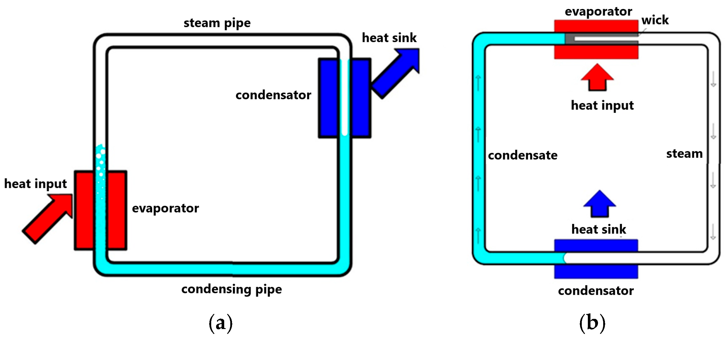
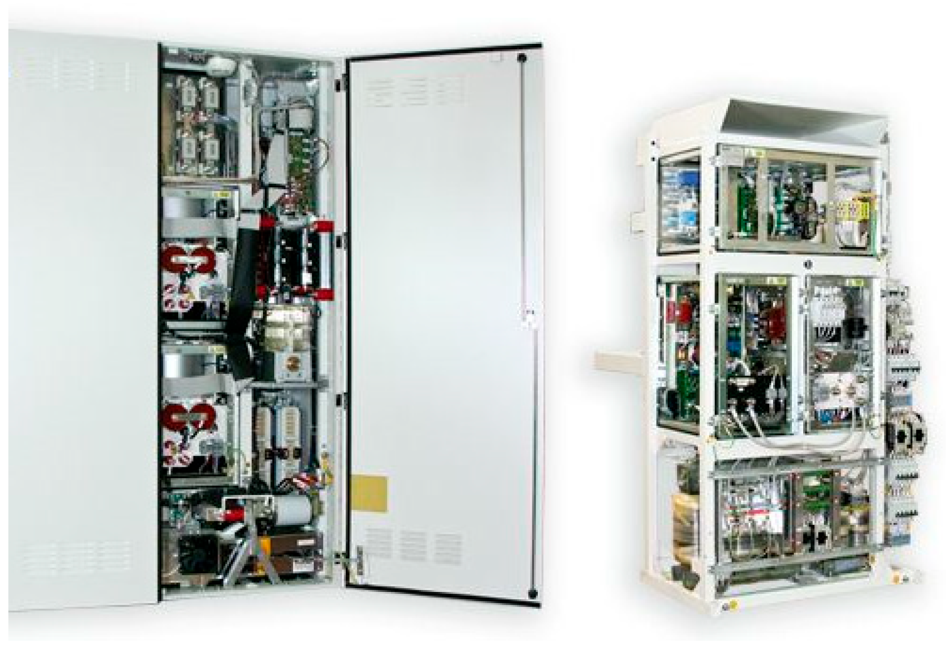
Adequate cooling of static power converters is one of the main requirements for their error-free and safe operation. It was the need to reliably dissipate heat loss from the electronic components of power converters that motivated the experimental research on cooling systems using the specific properties of heat pipes. Static energy converters are predominantly cooled by forced convection (
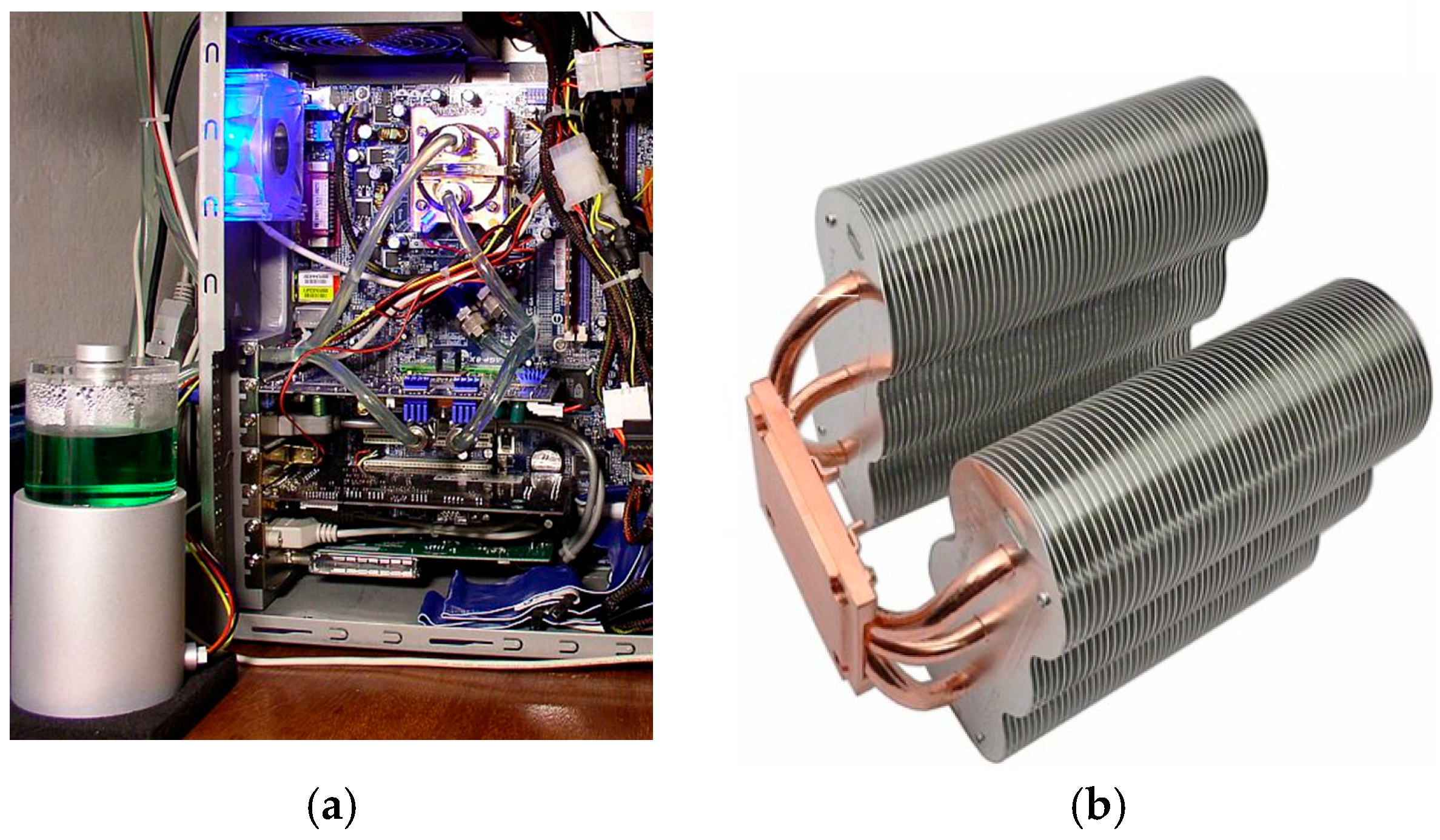
Figure 1a) of heat from power electronic and passive elements through standard finned heat sinks (
Figure 1b). For reliable heat dissipation, the cooling air flow is provided by a fan system or liquid circuits with forced movement of the heat transfer medium.
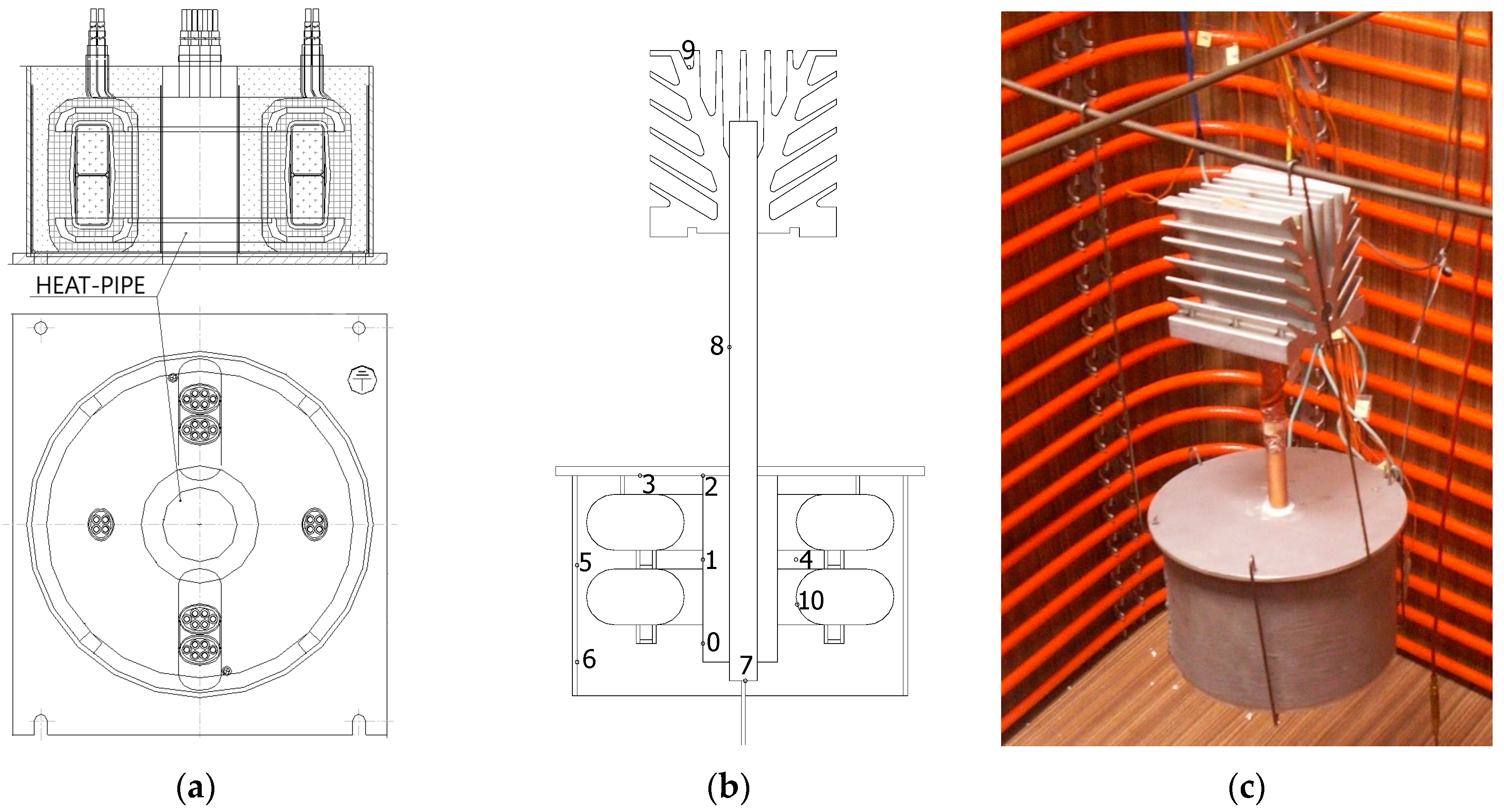
One of the first tasks was to solve the heat dissipation from the inner side of the energy converter (
Figure 2), which is normally encased in epoxy insulation.
While fins could be placed on the outer wrapping and substantially increase the heat exchange surface, this was not possible with the inner winding. Therefore, we removed the lost heat from the central compartment with a gravity heat pipe, the evaporating part of which was encased in epoxy insulation and the condensing part of which was cooled by natural convection. Initial experiments and experience with the design of heat pipes have already indicated their considerable application potential in a number of thermal management problems in facilities where heat has to be supplied or removed under specific conditions. The gradual discovery of the remarkable properties of heat pipes has also led to further application areas not only in electrical engineering, but also in environmental engineering and in power engineering.
In this paper, we review the use of different types of heat pipes in the removal of waste heat from electronic components and electrical enclosures, in increasing the efficiency of small heat sources, in energy storage, in the recovery of low-voltage heat from ventilation systems and geothermal ground boreholes, as well as in the use of nanoparticles to intensify the boiling of the working substance in the evaporator of the heat pipe. All the experiments presented in the thesis are carried out at our workplace by the author collective and address the actual issue of heat transport in different thermal devices.
2. Heat Pipe
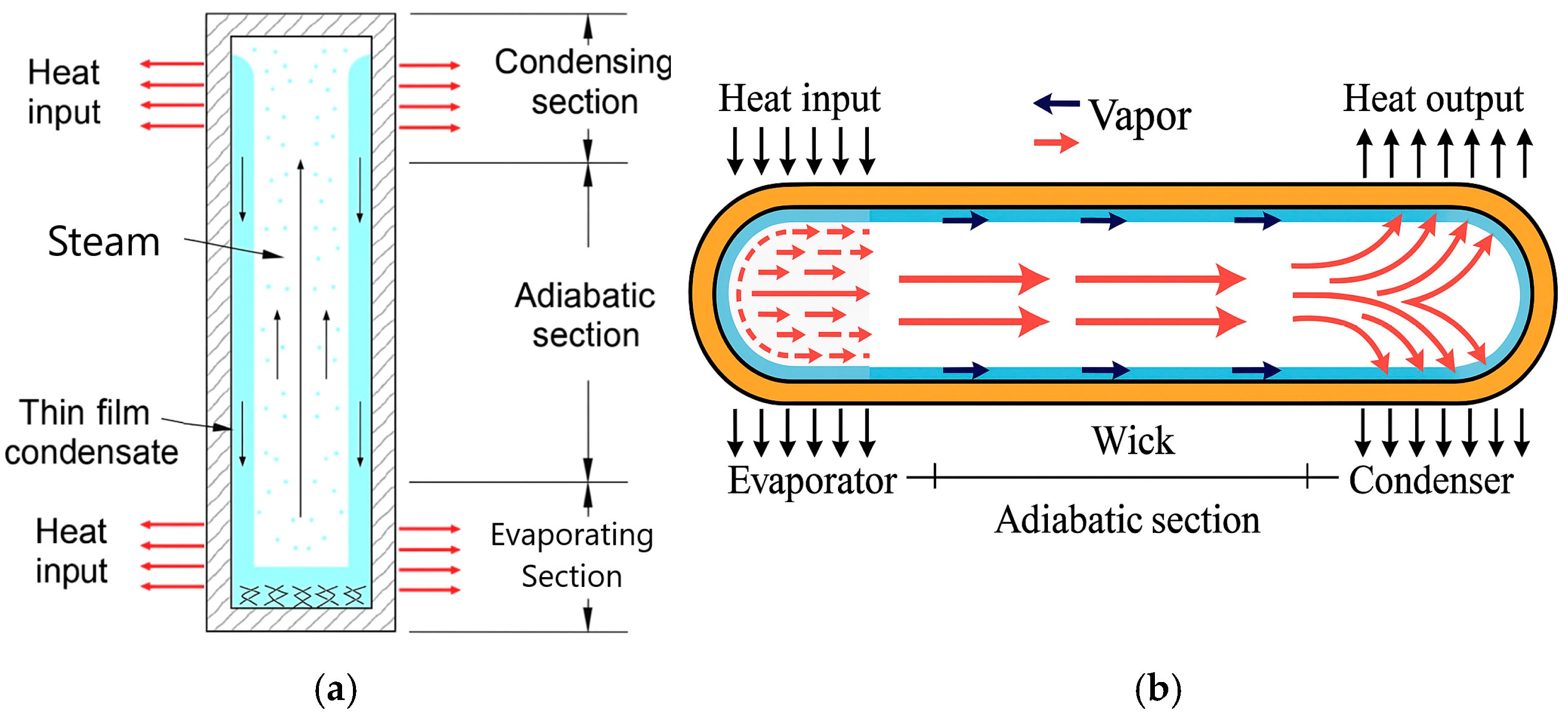
A heat pipe (
Figure 3a,b) is a device used to transfer heat by phase transformation and with a high heat flux density. It contains a working medium (alcohol, water, mercury, ammonia, helium, Freon…) in two phases at a certain pressure dependent on temperature. By heating one end of the tube and cooling the other, the medium is circulated so that at the heated end the medium evaporates and the vapour moves to the cool end where it condenses back to a liquid and, by spontaneous fall or rise through the capillary structure, the liquid again reaches the warm end, where the process repeats itself again. This creates a forced circulation of the working substance associated with heat transfer [
1,
2].
The heat flux transferred by the working substance from the evaporator to the condenser is many times greater than the heat transferred by a solid body, made of the best heat-conducting material, which has the same dimensions and the same temperature difference between the ends of this heat pipe.
Advantages of using heat pipes:
- -
Heat transfer even with small temperature differences at the ends of the tubes (around 2 °C);
- -
They have no moving parts and do not need additional equipment;
- -
Ease of installation and ease of design.
The heat output that is transferred through the heat pipe depends on its operating temperature. This should be identical to the working temperature range of the working substance. At very high working temperatures, when the whole substance is in vapour form, condensation does not occur, and heat transfer stops, and, conversely, at very low temperatures, when the entire substance is in the form of liquid, there is no evaporation, and heat transfer also stops [
2].
The selection of the working medium depends on the temperature range of the tube, the required evaporation and condensing temperatures, the pressure inside the tube, and the ambient pressure. An overview of some frequently used working fluids is given in
Figure 4 [
4,
5].
2.1. Distribution of Heat Pipes
Heat pipes can be classified according to the operating temperature (type of working substance), the shape of the construction, the possibility of use, the amount of working substance components, the method of condensate transport, and the method of non-condensing substance control.
According to the condensate transport method, heat pipes can be divided into three basic types [
2,
6,
7]:
2.1.1. Gravity Heat Pipe
This type of heat pipe is the simplest in terms of design, principle, function, and method of condensate return. The gravity heat pipe is a simple type of tube which is made of a smooth-walled tube and filled with a working substance at a defined pressure. The return of the working substance condensate from the condensing to the evaporating part is only possible by flowing down the inner wall of the tube due to gravity. The working position of the gravity heat pipe shall be vertical or inclined, with the condensing part positioned above the evaporating part in such a position that the condensate replenishes the liquid phase in the evaporating part in sufficient quantity due to gravity. The correct operation of the gravity heat pipe is conditional on the amount of working substance being such that, within the range of its operating parameters, there is no insufficient wetting of the surface of the evaporating section, otherwise the heat transfer may be reduced. On the other hand, too much liquid in the evaporator section will lead to the development of large vapour bubbles during boiling and thus shock phenomena. The heat flux transferred is also dependent on the thermal resistance of the liquid film on the wall of the condensing section. The advantage of the gravity heat pipe is that it is capable of transferring large heat fluxes. The disadvantage is that it has a limited working position and operates only in the position with the condenser positioned above the evaporator [
1,
2].
2.1.2. Capillary Heat Pipe
This type of heat pipes has a capillary system on the inner wall through which the condensate is transported by capillary pressure. They are most often horizontal but can also work against gravity up to a limited height. When the evaporator is heated, the working fluid evaporates from the pores of the capillary-porous wall into the space of the tube. As this happens, the vapour pressure in this zone increases. At the same time, as the condenser cools, the vapour pressure in it decreases. Under the influence of the resulting vapour pressure differences, the vapour in the tube flows from the evaporator to the condenser, where it condenses. The liquid is then absorbed into the pores of the capillary-porous wall structure and transported by capillary forces from the evaporator to the condenser, where it is re-vaporised. In this way, the heat pipe operates on the principle of a closed evaporation–condensation cycle. At temperatures far from the critical temperature, the vapour velocity generally greatly exceeds the fluid velocity in the capillary-porous structure. The high heat-transfer capacity of heat pipes is achieved not only due to the circulation of the working fluid at high vapour velocity, but also due to the high latent heat of vaporisation and condensation.
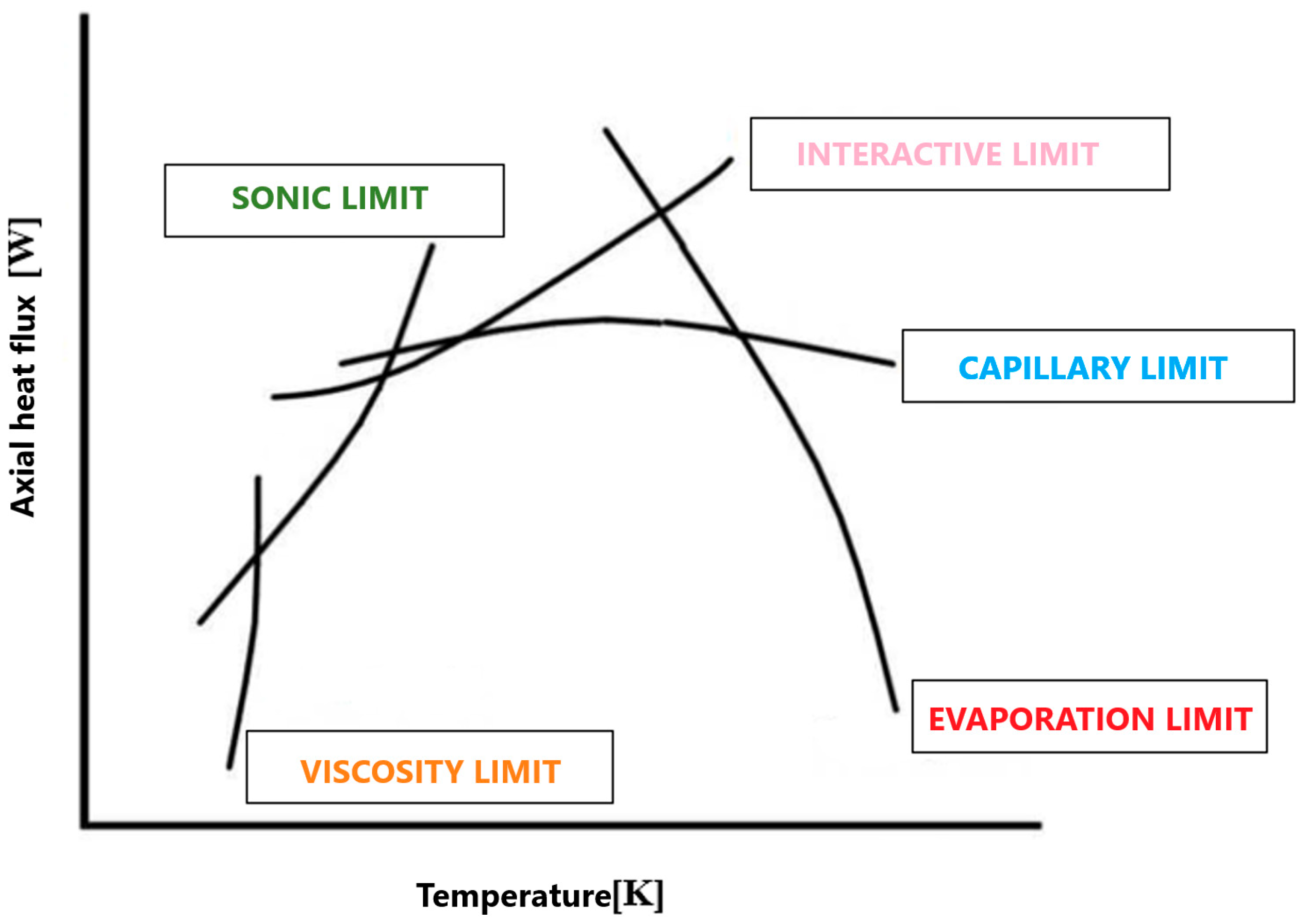
Despite the high heat transfer efficiency of the heat pipe, this heat transport is influenced by the limits of the heat pipe. Limits (
Figure 5) refer to phenomena in the heat pipe that reduce the amount of power transferred through the heat pipe. These limits depend on the choice of working substance, capillary structure, material, dimensions, and operating temperatures. For the operation of the heat pipe, the delivered heat input plays the most important role, on which the mass flow of the working substance in the pipe depends.
The viscous limit occurs when the operating temperature is extremely low, and the applied heat load is also low. The sonic limit usually occurs in heat pipes filled with liquid metal. It can be observed when the heat pipe starts up at low operating temperatures.
The capillary limit in heat pipes occurs when the capillary pressures at the vapour–liquid interface in the evaporator and condenser are not as large as the frictional pressure losses due to fluid motion.
The interaction limit occurs when the mass flow of vapour is large enough to remove droplets of liquid from the surface of the capillary structure, causing drying of the evaporator and primary capillary structure.
The evaporative limit occurs at high heat fluxes. At this limit, bubble boiling occurs in the primary capillary structure and drying of the primary capillary structure occurs [
2,
6,
7,
8].
2.1.3. Heat Pipe with Closed Loop—Thermosiphon Loop
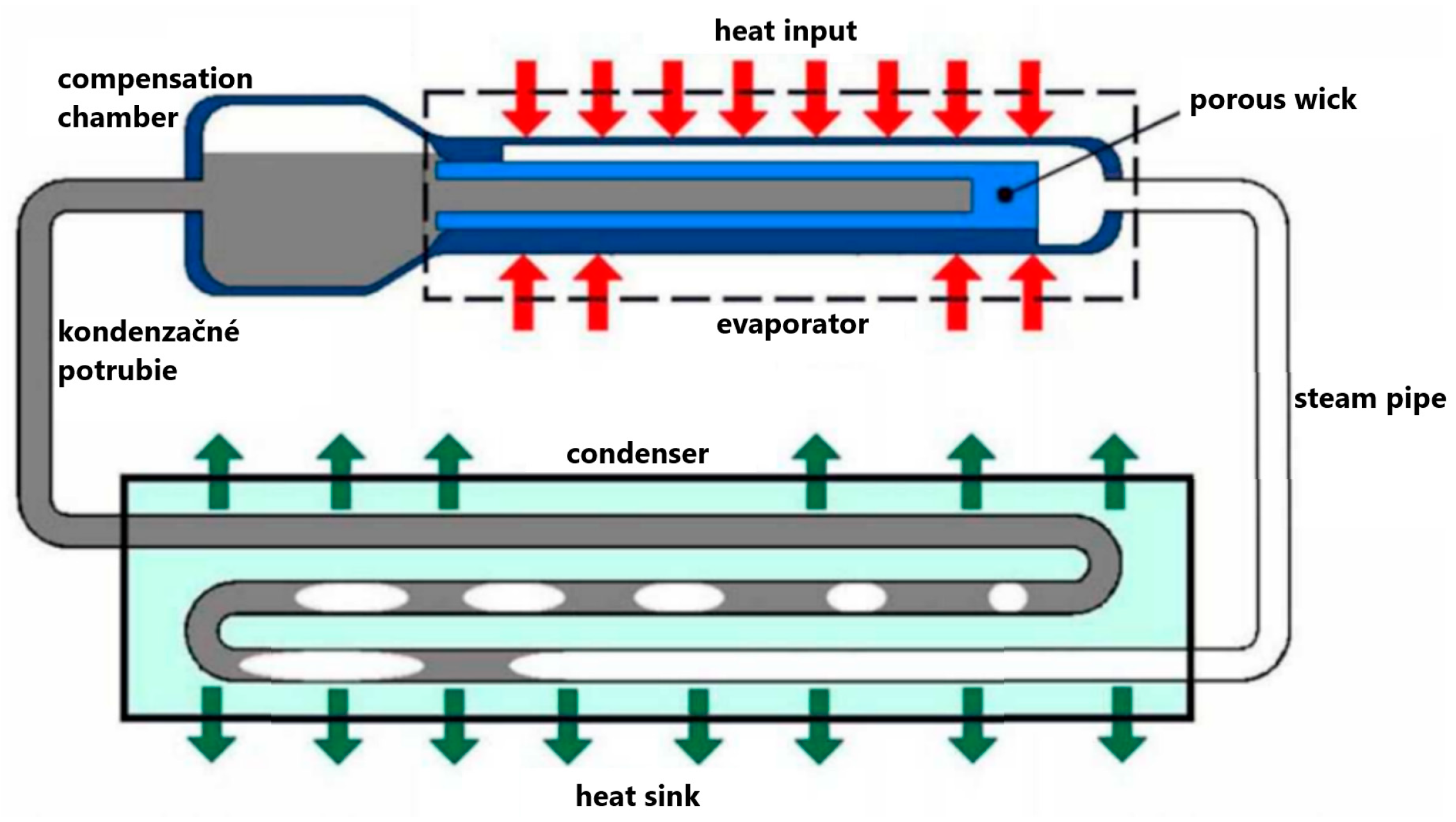
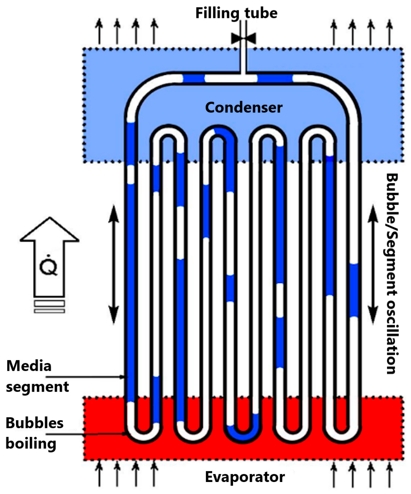
Closed-loop heat pipes (
Figure 6,
Figure 7 and
Figure 8) belong to single-component power pipes, which are divided into capillary and gravity. Loop heat pipes operate on the same principle as conventional heat pipes but have a separate condensate flow from the steam flow. The difference between them is in the way the working substance is circulated. While in a standard heat pipe the working substance flows between the evaporating and condensing parts in the same space, in a closed loop heat pipe the working substance flows between the evaporating and condensing parts in one direction in a closed loop [
2,
6,
8].
The medium in liquid form is fed into the evaporator where it is heated and evaporated. The saturated steam is led from the evaporator through a steam pipe to the condenser, where it condenses and is returned by gravity to the evaporator through a second pipe [
1,
2,
6,
7,
8].
3. Implemented Heat Pipe Applications
One of the directions of development of today’s electrical components is the miniaturisation of their dimensions and high integration, which often results in an increase in heat loss. Higher temperatures in these devices affect their operating parameters and can also cause their destruction. It is therefore often necessary to increase the heat dissipation from active or passive elements, but also from electrical enclosures.
3.1. Cooling of Assembly Boards and Elements in Electronics
The first application of the use of heat pipes to dissipate waste heat in electrical engineering was the use of a gravity heat pipe to dissipate waste heat from the inside of a static energy converter transformer (
Figure 9) for electric locomotives.
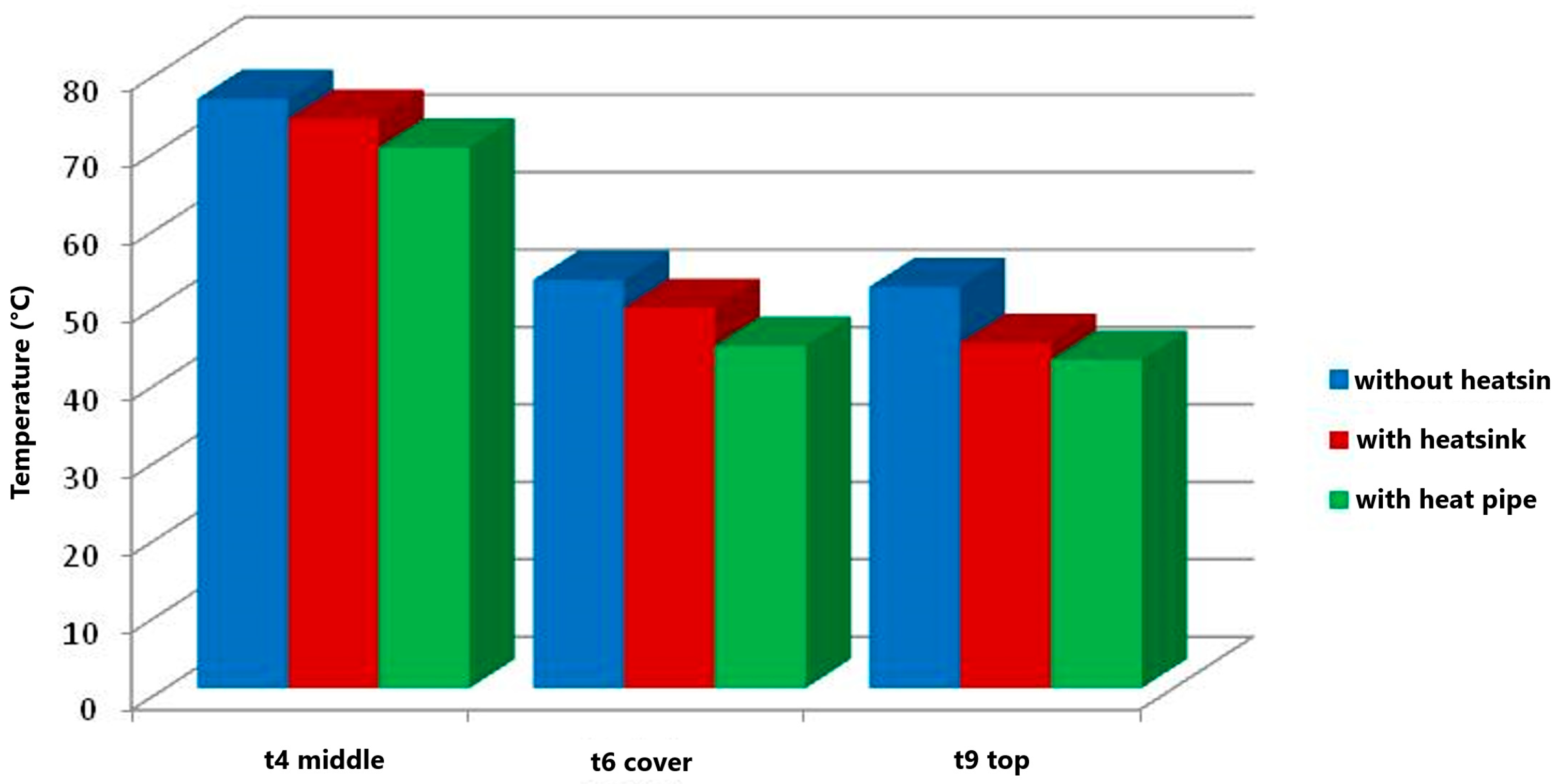
Figure 10 shows a comparison of the maximum temperatures reached on the transformer.
We used the simplest design of gravity heat pipe made of copper tube DN 18 with water and ethanol filling.
The principle of heat transfer by pulsed heat pipe was also used to cool the mounting plate [
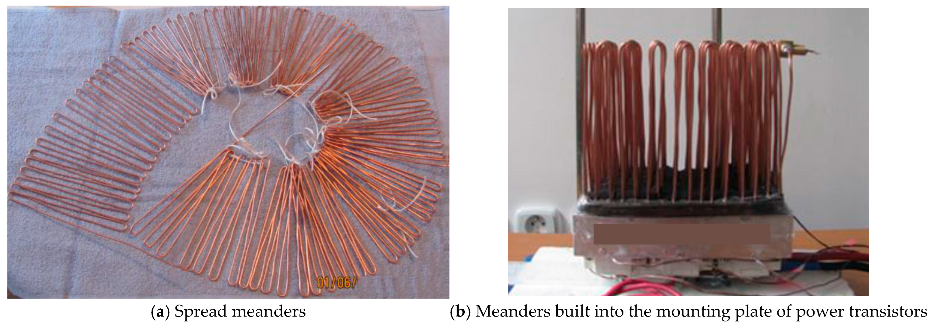
10]. The basic mechanism of heat transfer is associated with the pulsed motion of the fluid due to phase changes (evaporation and condensation). For the operation of the heat pipe, capillary forces must be used to form the liquid and vapour phases. An example of the implementation of heat removal from a plate by a pulse tube is shown in
Figure 11.
Based on the results obtained, it can be concluded that the constructed Fluorinert FC72 pulsating heat pipe is a suitable device for heat dissipation from electronic components at a maximum heat loss capacity of 100 W.
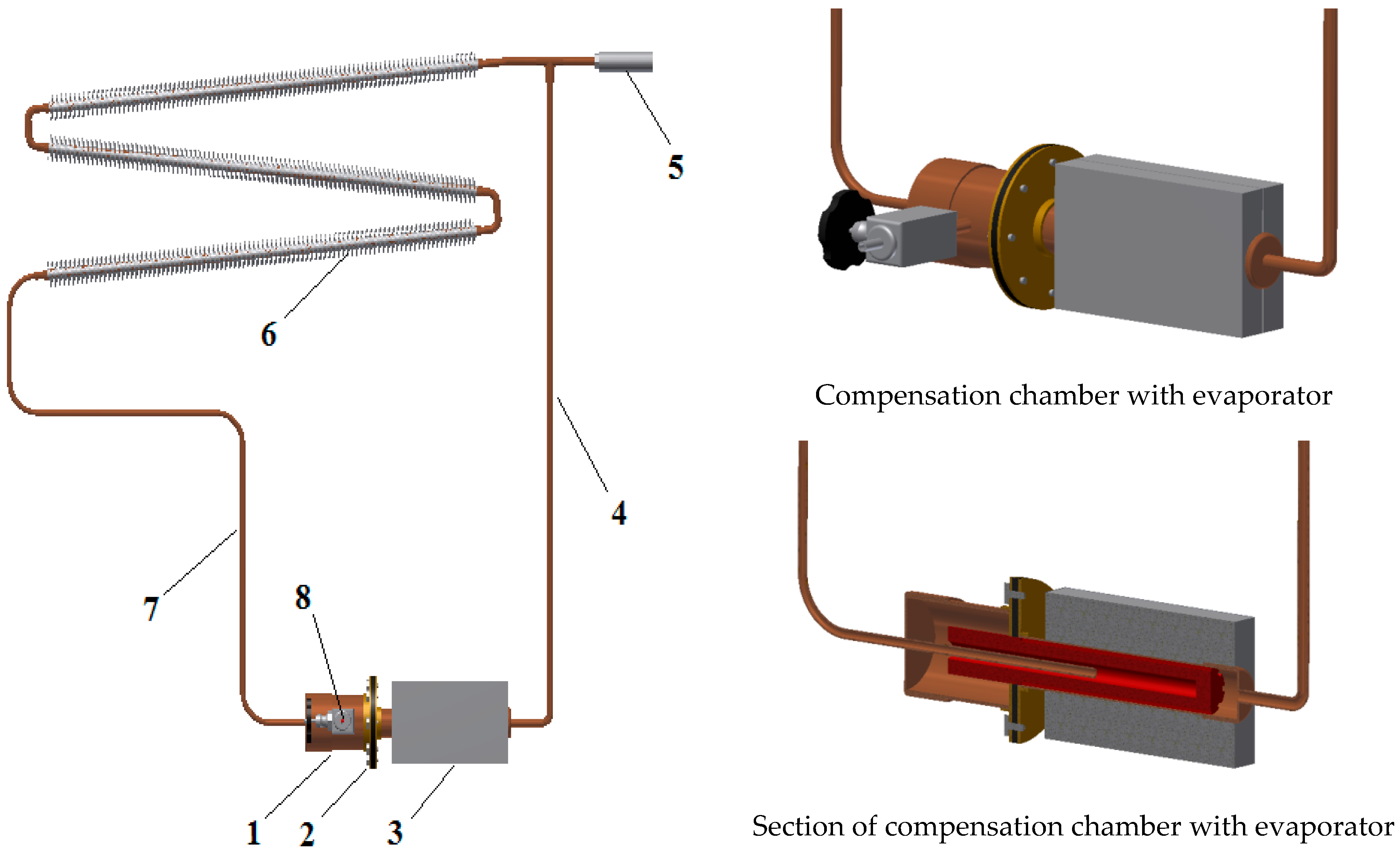
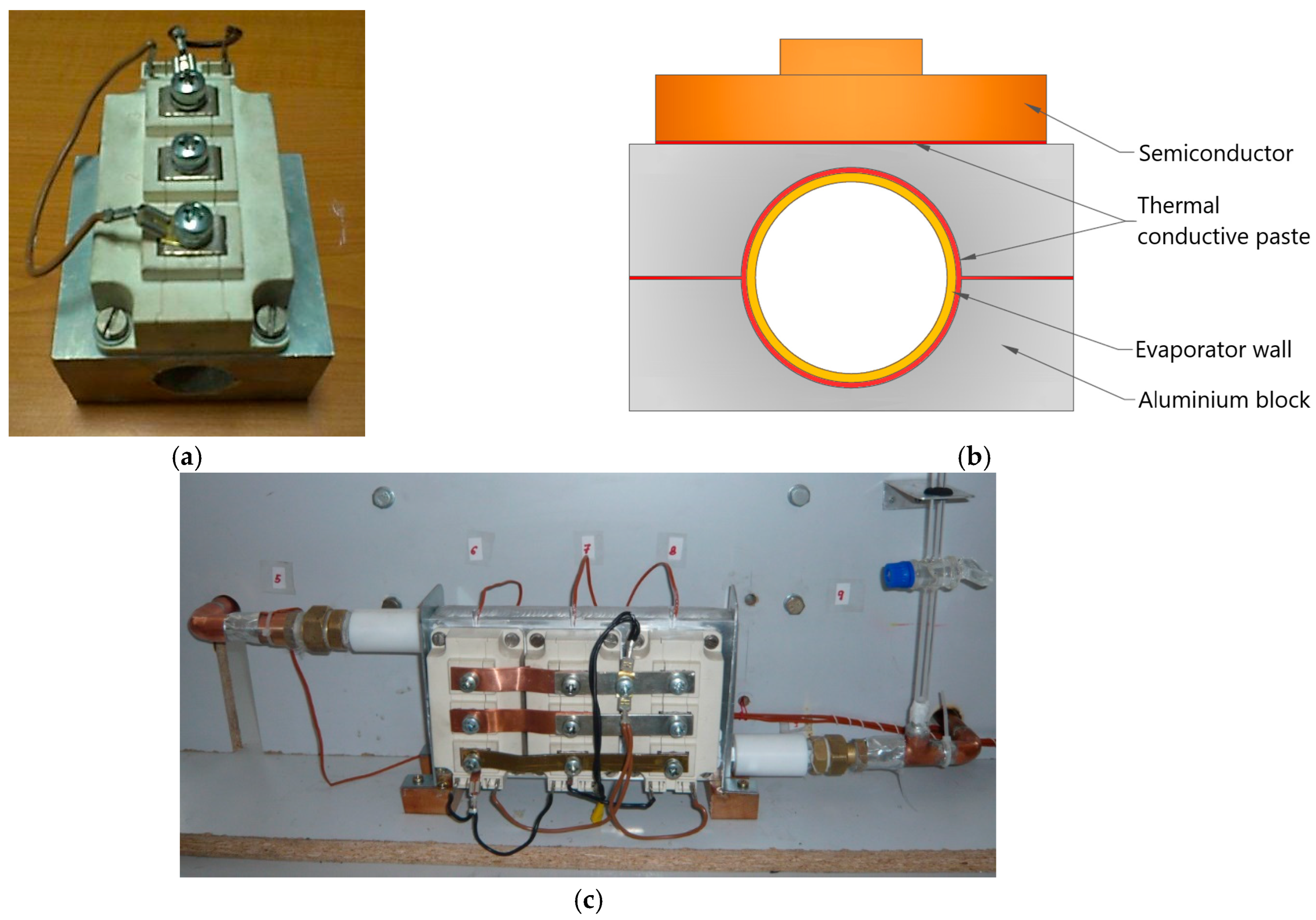
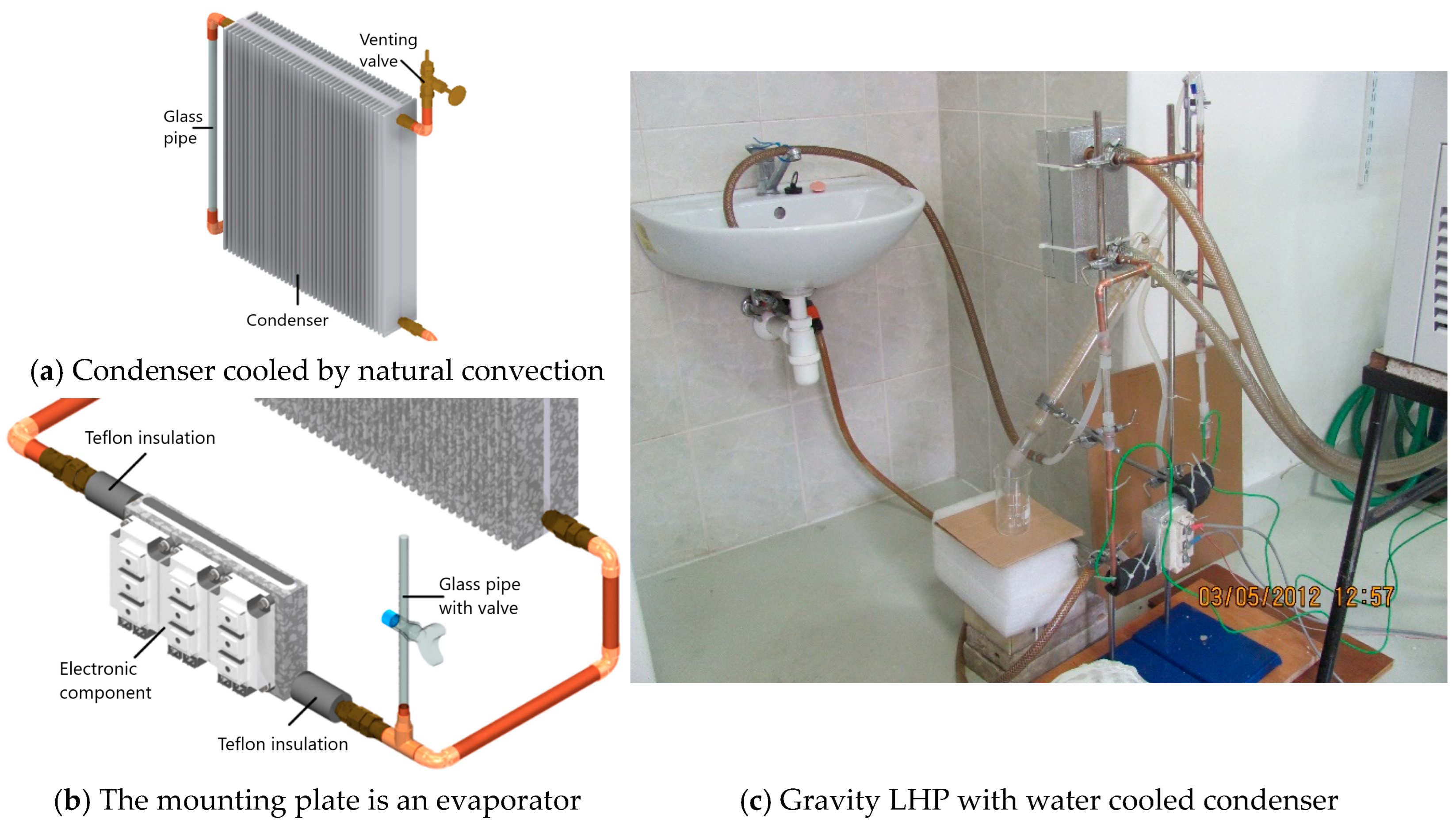
One of the available and effective solutions for heat dissipation from individual power electronic elements (
Figure 12,
Figure 13 and
Figure 14) by a closed loop heat pipe (LHP) appears to be the very advantageous use of a closed loop heat pipe with Fluorinert FC 72 working substance (
Figure 12).
3.2. Airtight Cooling of Electrical Enclosures by Closed Loop Heat Pipe
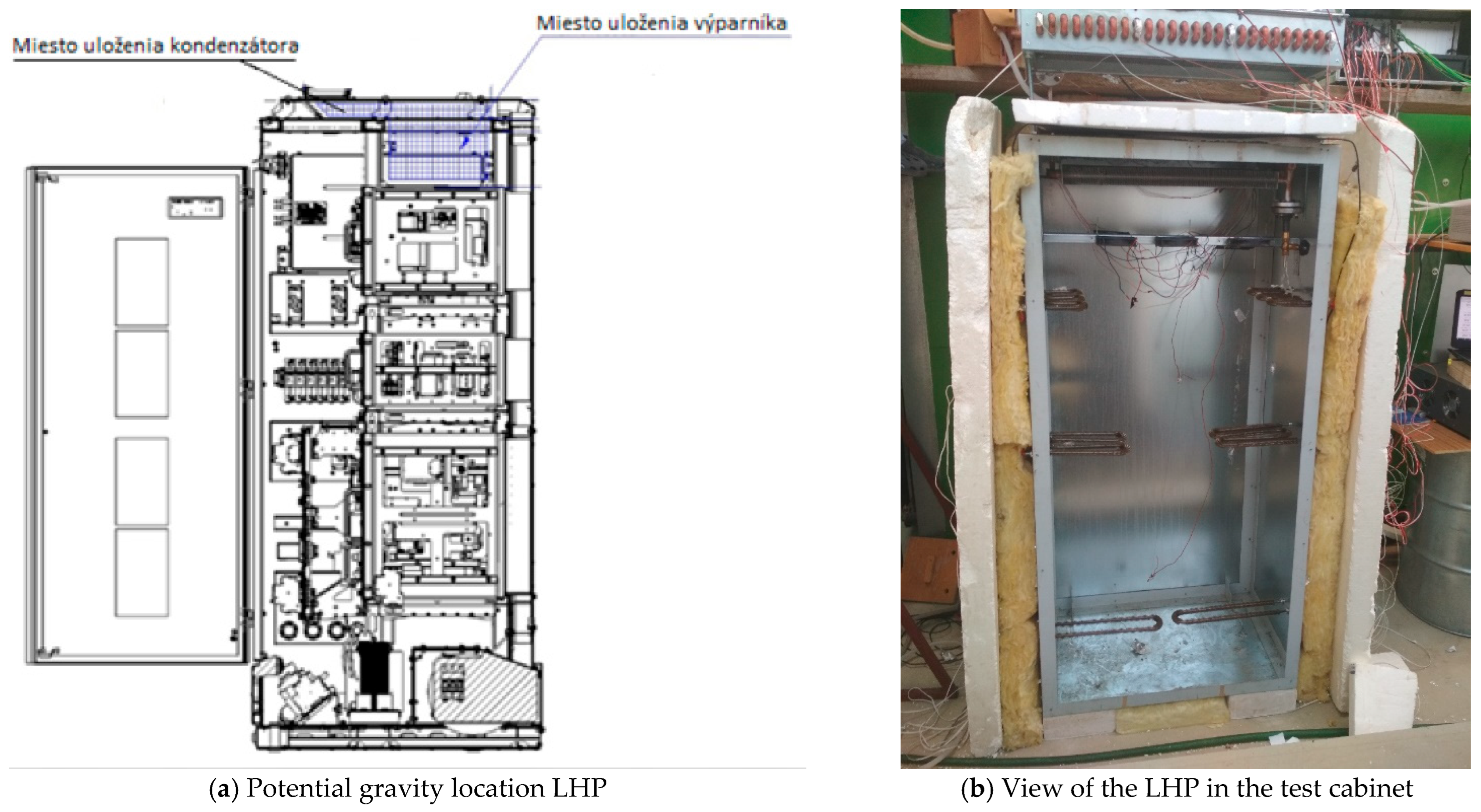
A static energy converter enclosure was used to test the potential for dissipation of waste heat from the electrical enclosures (
Figure 15,
Figure 16 and
Figure 17) [
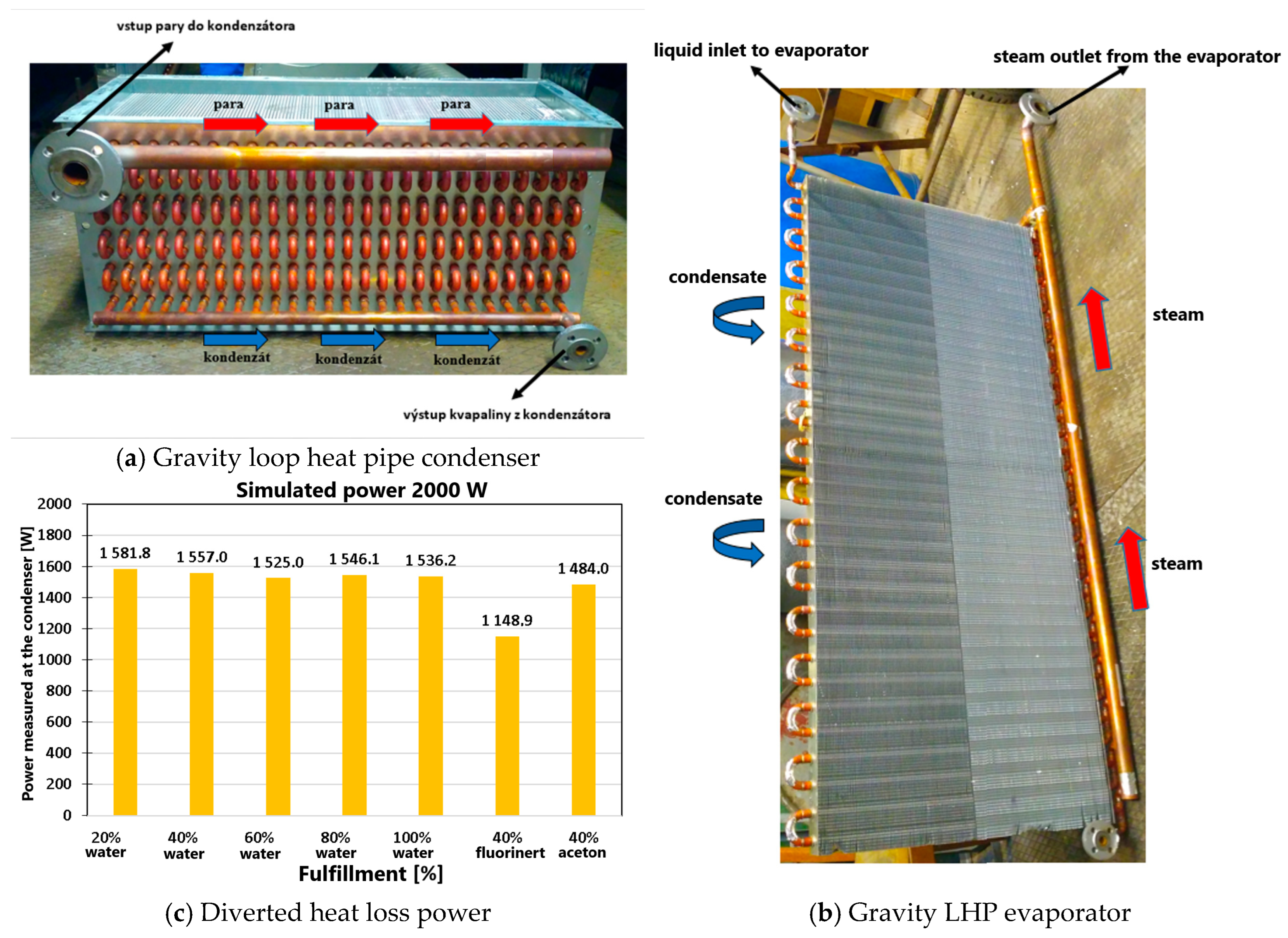
11]. It is a power electronic device with no moving parts that converts electrical energy parameters of one kind (magnitude and time history of voltage and current, frequency, and number of phases) into other desired parameters. The heat pipe has also proved to be quite a promising device for the dissipation of stray heat in this case. A very important advantage of using a heat pipe cooling device is the possible dust-tight sealing of the electronic equipment and thus the prevention of contamination of the electronic components by the deposition of dust from the cooling ventilation system. The electrical cabinet was hermetically sealed with sheet metal parts without ventilation grilles. The heat loss was dissipated by forced convection heat transfer from the flowing air to the evaporator of the gravity straw tube inside the enclosure. The steam and condensate flowed between the evaporator and condenser through two tubes of corresponding diameters, which had a dust-tight passage in the wall. The finned condenser was cooled outside the interior of the cabinet by natural or forced convection. The HP LOOP charge was water, acetone, and Fluorinert 72 (3M—Czech republic, Praha,
www.3M.cz); the maximum temperature inside the enclosure was about 70 °C, the ambient temperature was 25 °C, the heat output dissipated through the heat pipe was about 1500 W, the evaporator was located at the rear wall, and the condenser was above the enclosure. The most efficient was water, then acetone, and Fluorinert 72. Steam and condensate flow in separate pipes; condensate flows by gravity. Analytical models were developed to simulate the heat pipe operation, to simulate the condition in the heat pipe, and the heat transfer at known temperature and flow velocity on the outside of the evaporator and condenser, and their geometries.
3.3. Implemented Applications with Heat Pipes in Environmental Technology
Due to the wide range of issues related to creating thermal comfort, reducing the energy consumption of heating and ventilation, increasing the energy efficiency of equipment and the use of low-temperature heat, environmental technology offers many opportunities to improve existing systems and equipment by exploiting the specific properties of heat pipes.
3.3.1. Design of a Device to Reduce the Radiation Output of a Fireplace Insert Using a Loop Heat Pipe
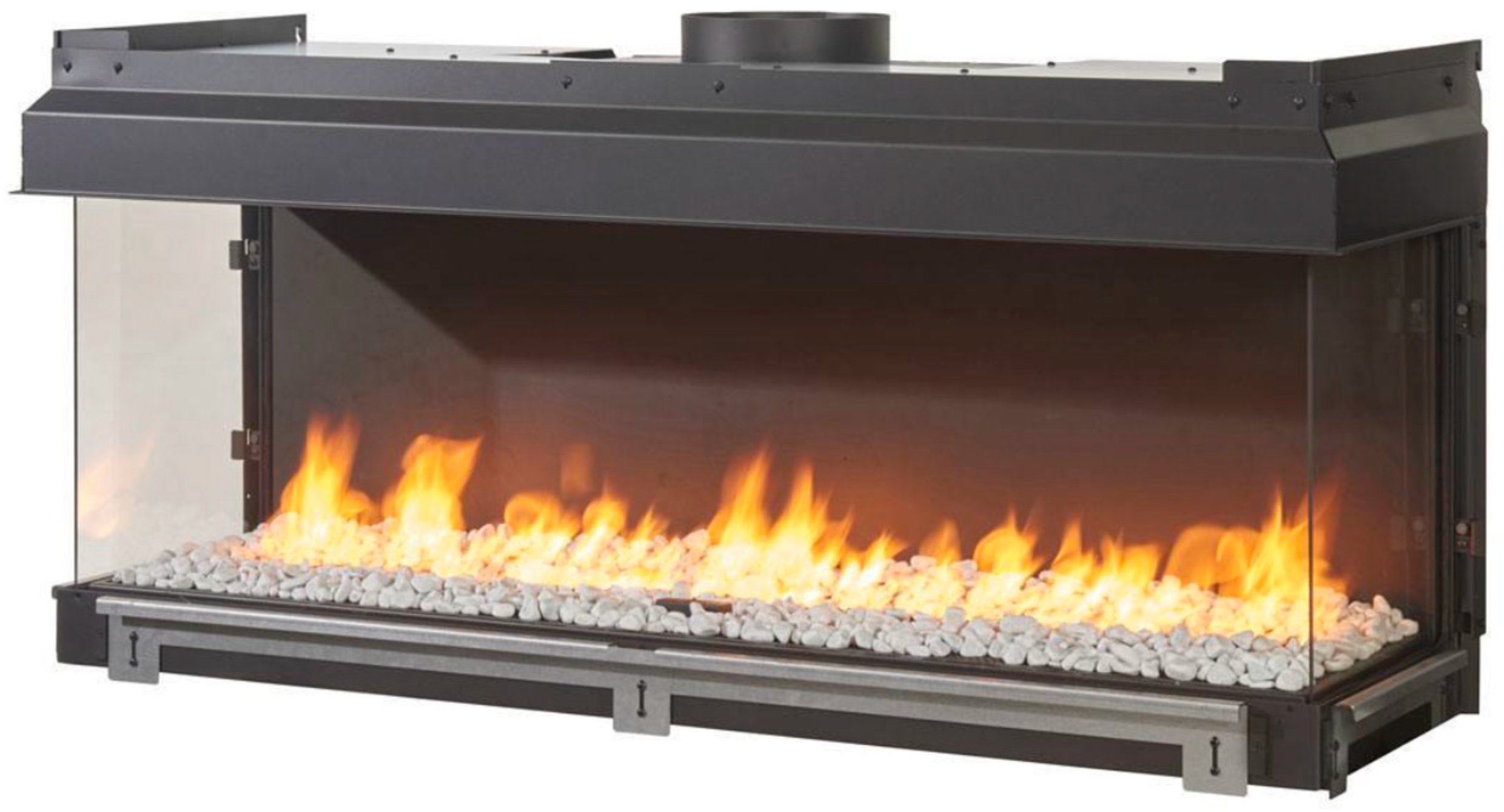
Recently, an interesting trend in the construction of fireplaces and stoves has taken hold. Customers choose fireplace inserts (
Figure 18) with large heating elements for the visual effects of burning fuel. The heat output of such a heat source tends to be more than 10 kW and the heat loss of an entire low-energy house with several rooms tends to be well below 10 kW under calculated conditions, so the use of a large fireplace insert leads to significant overheating of the room.
One option to meet the conflicting requirement of significant flames and reduced radiant heat flux to the room is to remove some of the heat output from the heating system and divert it, e.g., to a hot water accumulator (HWA) and use the accumulated heat in the heating system [
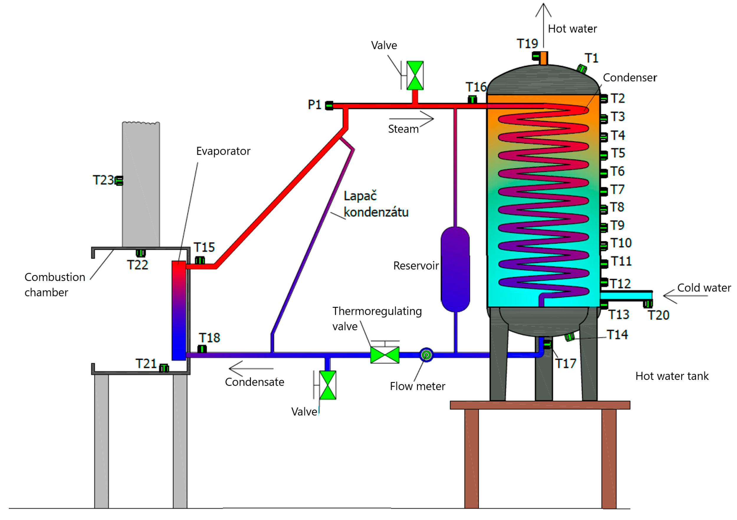
12]. Also, in this case, it is possible to use the properties of the gravitational loop tube—thermosiphon loop. In order to extract the heat from the fireplace insert, transfer it, and then use it to heat the water in the storage tank, a system of heat exchangers was designed (
Figure 19) [
13,
14].
The results of the experiment in
Table 1 showed that the use of a Loop HP evaporator built into the firebox of a gas fireplace insert (GFI) significantly redistributes the total heat output released by the combustion of natural gas in the burner of the fireplace insert. While a standard PKV without heat storage has a stack loss of approximately 19.9%, and up to 80% of the total heat input of the PKV is diverted to the interior, when the proposed Loop HP heat removal system is applied to the PKV firebox, the stack loss is reduced to 15.8%, up to 36.2% is diverted to heat storage, and the heat output is reduced to 58% of the total heat input to the interior. If in the case of PKV without Loop HP about 6152 W were going to the interior from the tested liner, with the application of Loop HP and heat accumulation only 3630 W, i.e., the heat output to the interior, was reduced by about 41%.
The main criterion for the selection of the heat pipe was, first of all, the price of the additional phase change heat transfer system, then the required heat transfer capacity, and the possibility of incorporating the designed system into the existing equipment.
Initial experiments showed that the cardinal problem of the large-scale evaporator is to optimise the bypass of the evaporator wall by condensate in a closed-loop gravity heat pipe. Therefore, it was necessary to design the condensate distribution system such that the liquid fed to the wall flows around the entire vertical surface of the evaporator uniformly.
Figure 20a shows the distribution of the original condensate distribution through the pipe with holes Φ = 1 mm with a uniform spacing of 50 mm, and
Figure 20b shows the condensate distribution adapted to the entire evaporator wall.
If the condensate can be distributed over the entire evaporator wall area, then the maximum effect of reducing the radiant flux from the HPC to the heated room can be expected.
3.3.2. Increasing the Efficiency of Small Heat Sources with the Use of Heat Pipe
Currently, small heat sources (SHS) achieve relatively high efficiency (85 to 88%), yet SHS experience heat losses, of which the most significant is the stack loss [
14,
15,
16,
17,
18,
19]. By removing some of the otherwise unused heat from the flue gas, we have the opportunity to reduce the largest heat loss, and by using this heat we can also increase the efficiency of the FGD by removing some of the heat from the flue gas and then using it to preheat the combustion air using a loop thermosyphon (LHP). The proposed device for increasing the thermal efficiency of the MZT consists of a loop heat pipe (LHP), the evaporative part, which is located before the inlet to the chimney, where it removes part of the heat from the flue gas and through the steam pipe of the LHP the heat is transported in the form of steam to the condensing part of the LHP located in the combustion air inlet duct. After the heat has been transferred to the combustion air, the condensate is transported by gravity through the condensing duct back to the evaporator, where it is again converted to steam and the cycle is repeated.
The flue gas temperature reaches quite high temperatures, so we have chosen water as the working medium, which is one of the most widely used working media in thermal management. It has very good physical properties, it is available, it is without harmful impact on the environment, and it is neither poisonous nor flammable. When selecting a wall material, not only its thermal conductivity, which is ideally as high as possible, is a decisive factor, but also its compatibility with the working medium has a great influence [
20]. The right compromise between wetting and chemical stability must be found to avoid corrosion and the formation of non-condensable gases.
The method of increasing the efficiency of fireplace inserts (
Figure 21) by removing part of the heat output from the flue gases and using it to heat the combustion air or to use it for heating is proving to be feasible.
By removing part of the heat output using a closed-loop heat pipe (LHP), the flue gas temperature is reduced by 20 °C to 50 °C depending on the flue gas temperature, thus increasing the efficiency of the heat source by between 2% and 5%. The advantage of using a closed loop heat pipe to increase the efficiency of the fireplace component is the synergistic effect of its operation. The heat output is greater the higher the temperature of the flue gas in front of the chimney, which also has a significant effect on reducing the chimney loss of the heat source. However, in order to implement the above method of increasing the thermal efficiency of the MZT, the combustion air inlet needs to be modified to accommodate the Loop HP condensing section and to allow the condensate to flow naturally into the evaporator [
21,
22].
It has been shown that it is also possible to implement a flat evaporator with a capillary structure that can be placed in the soffit of the fireplace insert without compromising its aesthetic value. The condenser must be oversized rather than undersized to be able to use the condensing heat to the maximum extent possible. The use of finned tubes for the construction of the condenser has proved to be appropriate.
As already mentioned, the system must be considered when designing the fireplace insert. The combustion air supply duct must be located so as to provide a separate combustion air inlet in which the heating of the combustion air will also be carried out directly.
3.3.3. Using Gravity Heat Pipe for Low-Potential Heat Recovery from Rock
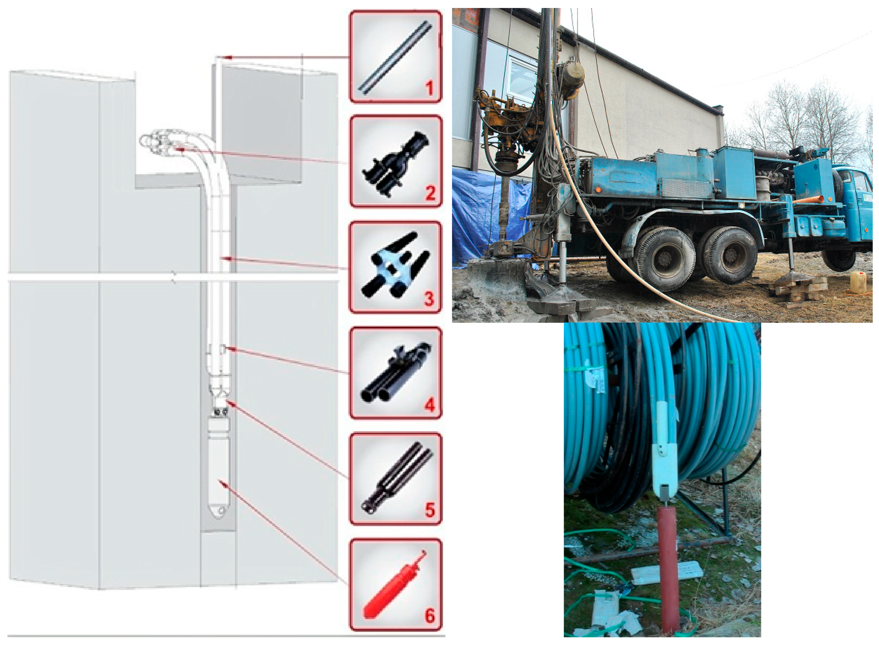
Two boreholes were previously built on the University of Žilina’s land for the introduction of ground probes for pumping low-potential ground heat. In one borehole (
Figure 22), a traditional earth probe was used with a circulating pump transporting the working fluid. In the second borehole, heat pipes were installed using ammonia as their working fluid [
23].
For the primary section, a PE-XA ground probe was chosen (
Table 2—bottom right), which is used in common practice for the implementation of primary circuits of heat pumps. These piping systems, which are resistant to the conditions in the rock mass, are designed to work with different heat-bearing substances (ethylene glycol, brine, etc.) [
24].
Figure 22.
Deep borehole cut and drilling rig (
top right), termination of the PE-XA earth probe with weights (
bottom right) [
25].
Figure 22.
Deep borehole cut and drilling rig (
top right), termination of the PE-XA earth probe with weights (
bottom right) [
25].
The difference between the performance obtained by the conventional forced circulation method of the working substance compared to the heat pipe (TT) was considerable, and it is clear that the heat pipe did not operate with the required efficiency. This may be due to a number of factors affecting the correct operation of the TT.
Based on the measurements (
Table 2), several hypothetical reasons why the heat pipe did not operate with the same performance as the forced circulation ground probe were determined:
Insufficient surface roughness or wettability—this factor is important in the transfer of heat (α) from the rock to the heat pipe. If the condensed working substance does not flow evenly (spreading the NH3 film over as large an area as possible with as little thickness as possible), the heat transfer performance of the heat pipe may be reduced. If the flowing film occupies only a small percentage of the area of the TT tube, this phenomenon can have a significant effect on the obtained performance.
Unequal dosing of the working substance for individual TT U-tubes is also one of the possibilities that could have occurred in our case. Since TT consists of two independent U-tubes, the dosing of condensate in the exchanger section is not controllable and we cannot ensure equal supply to each of the U-tubes. This fact may cause that condensate from the exchanger section going to the bottom of the TT will flow into only one U-tube. This may result in a drop in TT performance due to the following:
Loss of functionality of one of the U-tubes (since it is empty, there will be no phase transformation in it).
Pressure rises due to the height of the NH3 column in the full U-tube (which would reach up to 60 m in the case of a full build-up in one of the U-tubes). It will increase the hydrostatic pressure and thus the total pressure acting in the well. If this were the case, the boiling of the liquid ammonia would be limited to a depth at which the pressure would not exceed the boiling point at a given temperature.
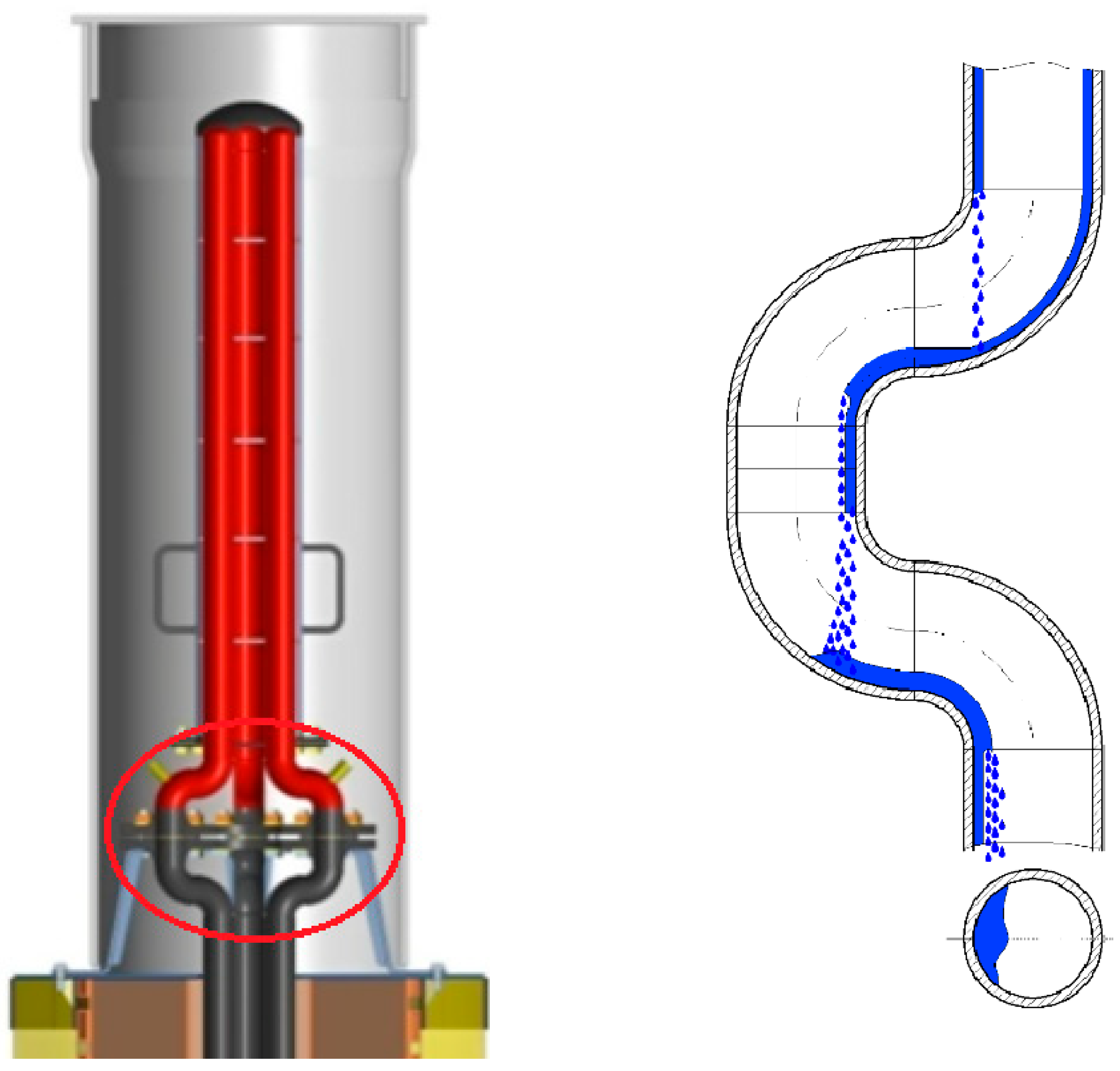
Uneven distribution of condensate around the perimeter of the heat pipe. This problem is associated with the use of unsuitable installation components designed for the flow of the working substance for individual U-tubes. In
Figure 23, these components are highlighted in the red circle [
25,
26,
27,
28].
The measurements were carried out on a simulator of low-potential heat transport into heta-pipes [
26]. These are actually two simulators. One for the working substance carbon dioxide, and the other for ammonia, shown in
Figure 24.
The first circuit is a custom simulator of low-potential heat transfer into a heat pipe. The device consists of a corrugated sewer pipe ø500 mm in diameter and 6220 mm long, around which 600 m of heating Devi cables are wound. These cables are divided into three separately adjustable sections and are used to simulate the action of the ground heat. Using Ni-CrNi thermocouples, the temperature of these cables can be measured, and the electrical power can also be measured.
Based on the large discrepancy between the results measured on the heat pipe and the traditional ground probe, and the listed reasons related to this discrepancy, measures were proposed that would be able to ensure ground heat extraction using the heat pipe at its full potential.
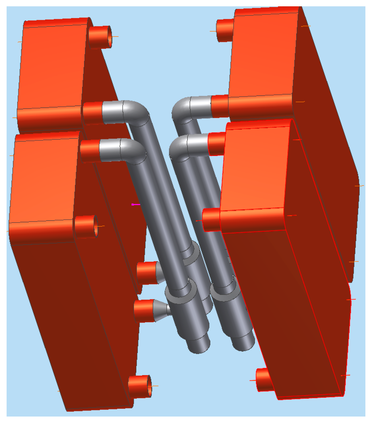
We propose to create four classic gravity heat pipes with plate condensers from two U-tubes above the borehole (
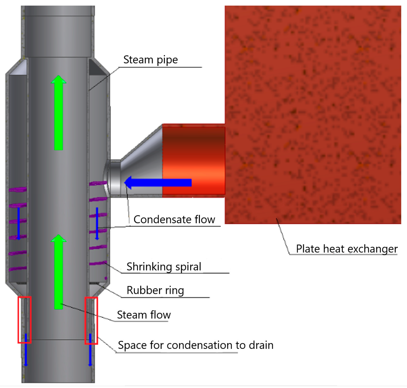
Figure 25) and to specially modify the condensate distribution around the entire circumference of the tube, according to
Figure 26, so that the condensate wets the entire inner casing of the earth probe tube.
3.3.4. Application of Thermosiphon LHP with Nanofluid for Heat Recovery in HVAC Units
Several types of nanoparticles have been investigated in the research on the effect of nanoparticles on the boiling in a heat pipe evaporator, because current research works do not provide sufficient information on the effect of nanoparticles on the processes in the heat pipe. Based on the research works, nanoparticles compatible with the environment, suitable for heat transfer, with good thermal conductivity and with different grain sizes, were selected.
Table 3 describes the properties of the selected types of nanoparticles. The aim of the experiment was to determine the type and concentration of nanoparticles with a positive influence on the heat transfer properties of the working substance [
29,
30,
31,
32].
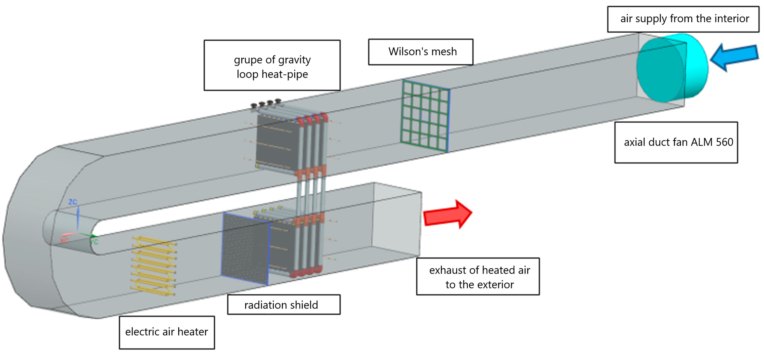
The properties of LHP in waste heat recovery in air handling systems were tested on the experimental device, according to
Figure 27, at the same mass flow rate of air through the evaporator and condenser parts of the duct [
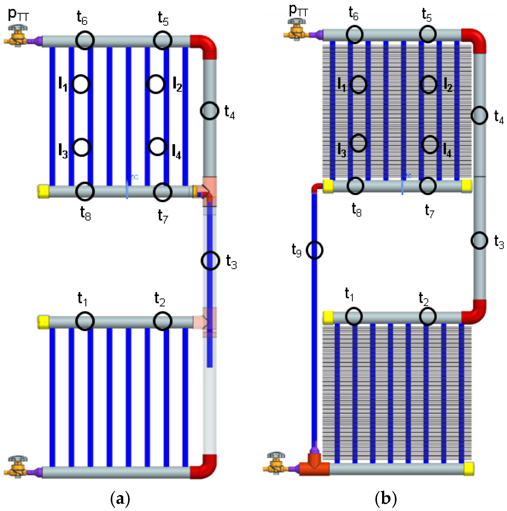
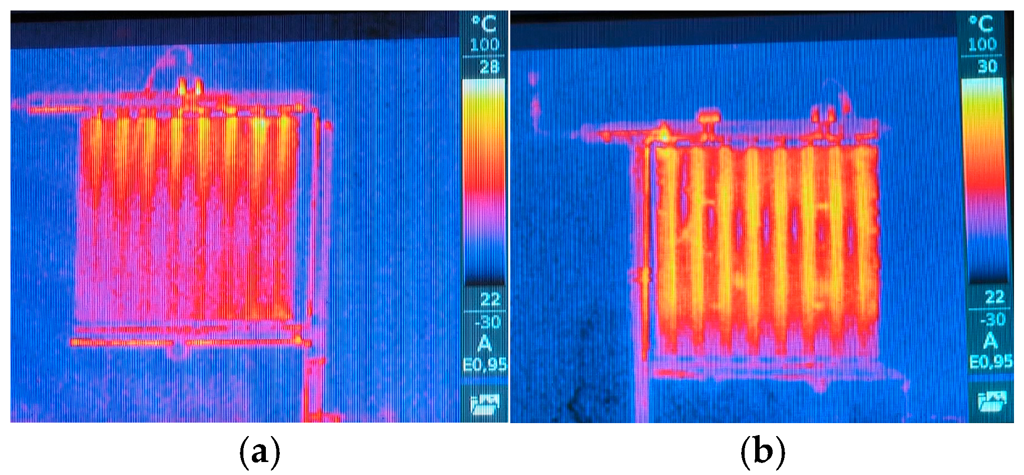
33]. The dynamics of heat transfer from the evaporator to the condenser was tested for two designs of the heat pipe (
Figure 28a,b and
Figure 29) by stepwise heating of the evaporator by immersion in a vessel of warm water of temperature 40 °C.
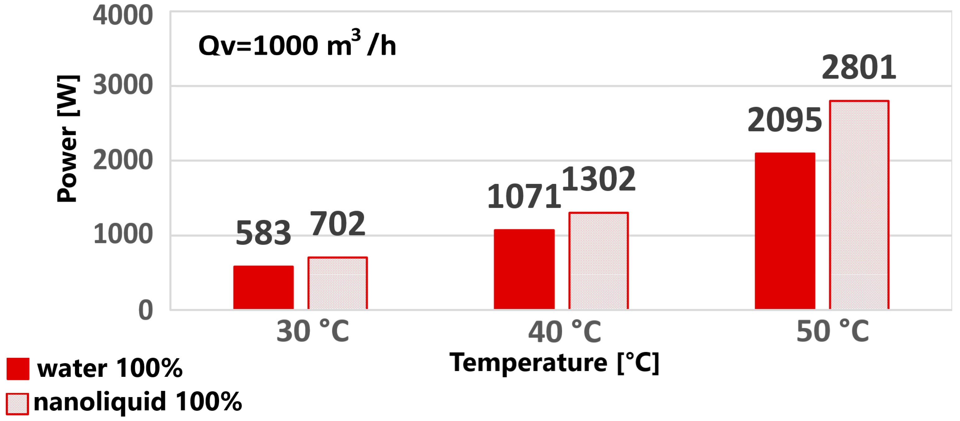
When comparing (
Figure 30) the working substances, the positive effect of the nanofluid on the boiling and on the evaporation of the working substance in the heat pipe was significantly shown. The nanofluids increased the performance of the heat pipe by at least 6% and up to a maximum of 33%.
3.3.5. Use of Thermosiphon LHP for Cooling and Heating of Metal Hydride in Hydrogen Storage
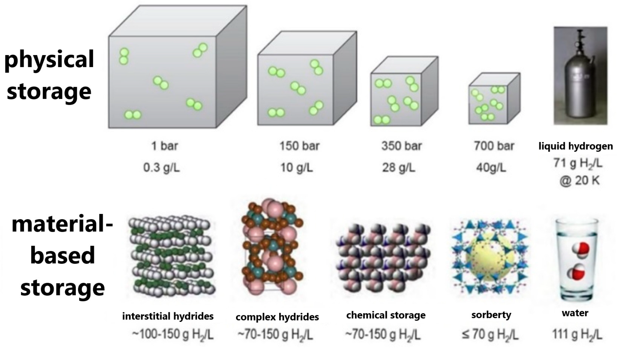
Hydrogen storage (
Figure 31 and
Figure 32) as a very popular form of green stored energy requires efficient systems that do not require operation at extreme pressures or deep cryogenic temperatures. It is proving to be energetically and safety advantageous to store this hydrogen in metal hydride alloys at relatively low pressures (up to 1 MPa) and near ambient temperatures [
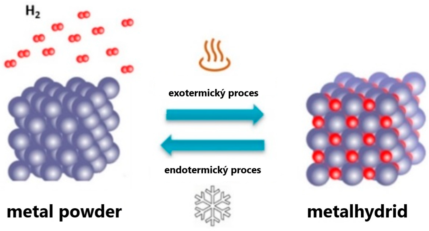
34]. During the process of hydrogen accumulation and expulsion from metal hydride, thermal changes occur, which are important to control and optimise.
The cooling and heating of a metal hydride storage tank (
Figure 33 and
Figure 34) are important processes that affect its performance, lifetime, and safety. In the hydrogenation and dehydrogenation of metal hydride, heat must be removed from the metal hydride alloy and supplied to the process and the required temperature must be maintained. And also, in this case we use the specific characteristics of a closed-loop heat pipe. In the case of metal hydride hydrogenation, the metal hydride must be cooled by boiling at an absolute pressure of approx. 14 kPa and a boiling point of 50 °C. In this case, the reservoir body acts as an evaporator and the condenser is cooled by ambient air. In dehydrogenation, at a temperature of about 160 °C and a vapour pressure of 0.618 MPa, the container body is the condenser of the LHP and the vapour is generated, for example, by the waste heat from the fuel cell in the evaporator. The thermal management [
37] is adjusted by a system of valves which change the functionality of the metal hydride storage body.
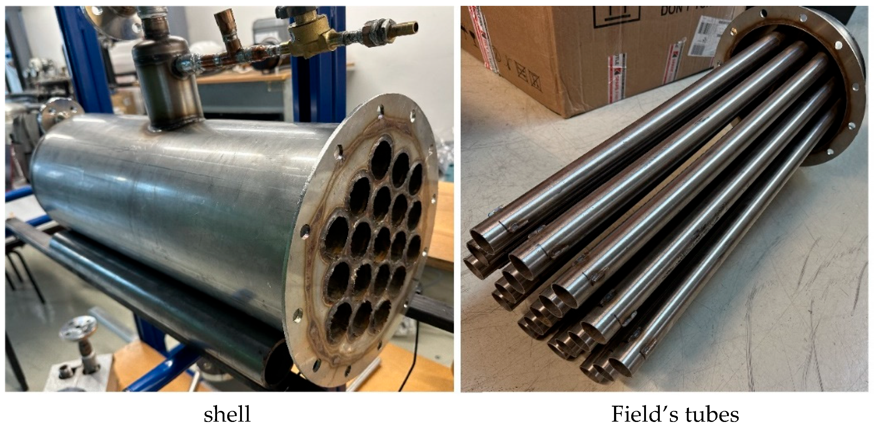
In order to investigate the above functionality of the metal hydride stack and to analyse the heat transfer processes, we have designed and implemented a metal hydride stack simulator with field tubes that simulate the filling of a costly metal hydride charge. The heating and cooling of the metal hydride stack simulator is performed using the closed-loop heat pipe operating principle due to the use of more efficient heat transfer during the phase transformation (boiling and condensation).
4. Conclusions
Heat pipes are an exceptionally efficient and flexible tool in thermal management, allowing reliable heat loss while maintaining simplicity of design and high heat transfer efficiency. In this paper, their basic principles, types (gravity, capillary, and loop), and practical applications in electrical, environmental, and energy engineering are presented in detail.
Based on the experiments carried out by the author’s team at their workplace and their analyses, it can be concluded that heat pipes represent an effective thermal management tool with a high variability of applications and measurable benefits in the investigated areas:
- -
Cooling of power electronic components: Both gravity and loop heat pipes were able to stabilise the temperature of power transistors at a lossy thermal power up to 100 W. The use of Fluorinert FC-72 working fluid ensured long-term reliability without external forced airflow.
- -
Fireplace inserts and small heat sources: The implementation of loop heat pipes in gas fireplace inserts has demonstrated a reduction in radiative transfer to the interior by up to 40%, significantly improving the controllability of the output. At the same time, it was possible to divert part of the energy to the storage tank, where up to 36% of the total heat output was stored (2735 W out of 7560 W). Convection transfer to the room was thus reduced from 58% to 34%, demonstrating the effectiveness of the condensate distribution treatment.
- -
Heat recovery in combustion plants: Measurements have shown that the inclusion of loop heat pipes in the flue gas extraction system resulted in a reduction of 20–50 °C in flue gas temperature and an improvement of 2–5% in the efficiency of small heat sources. This effect also reduces stack loss and increases operational safety.
- -
Geothermal applications: When compared to a traditional ground probe, the average heat transfer value of the heat pipe was 1900 W, whereas it was 4980 W for forced circulation probes. Although the efficiency was lower, the results point to the need to optimise the condensate distribution and the wettability of the evaporator surface.
- -
Nanofluids: The use of nanoparticles (e.g., Al2O3, TiO2, CuO) in appropriate concentrations can increase heat transfer efficiency by up to 30%. The tested particles with a particle size of 4–100 nm showed an improvement in the transport properties of the working medium.
Experimental applications in the field of cooling of power transistors, mounting plates, static converters, or electrical enclosures confirmed that the heat pipe not only allows us to increase the reliability of devices, but also to seal them without the need for active ventilation. The significant reduction in heat output to the interior with loop tubes when applied to fireplace inserts (up to 40%) demonstrates their potential in environmental engineering as well. Another interesting direction is the use of nanofluids, which can increase the efficiency of the tubes by up to a third, as well as the implementation in heat recovery systems in air conditioning or in metal hydride hydrogen storage tanks.
Despite the lower efficiency in some specific applications (e.g., geothermal heat recovery), heat pipes remain a promising solution, with the possibility to optimise the design and distribution of the working medium. It has been shown that a properly designed heat pipe can provide stable heat transfer without the need for external actuators and with the ability to operate in different positions and temperature ranges.
Overall, heat pipes allow heat flux densities of up to the order of tens of kW/m2 to be transferred at small temperature differences (as low as 2 °C). This makes them a promising solution not only in electrical engineering, but also in the optimisation of small heat sources, in air conditioning, and in modern hydrogen storage systems.
In conclusion, the development and application of heat pipes have great potential, not only for increasing the efficiency of cooling systems, but also for reducing energy losses and the overall sustainability of technical solutions. Further research could focus on the optimisation of condensate distribution, the development of advanced working fluids, and the integration into systems with high demands on reliability and energy efficiency.
Author Contributions
Conceptualization, M.M. and J.J.; methodology, M.M.; software, R.L.; validation, M.M., K.K. and P.N.; formal analysis, M.M.; investigation, J.J.; resources, M.M.; data curation, M.M. and R.L.; writing—original draft preparation, M.M. and K.K.; writing—review and editing, R.L. and K.K.; visualization, K.K. and R.L.; supervision, M.M.; project administration, M.M. and J.J.; funding acquisition, M.M., J.J. and R.L. All authors have read and agreed to the published version of the manuscript.
Funding
This research was funded by: KEGA 023ŽU-4/2024, VEGA 1/0670/23, VEGA 1/0680/23, KEGA 047ŽU-4/2022.
Data Availability Statement
The original contributions presented in this study are included in the article. Further inquiries can be directed to the corresponding author.
Acknowledgments
The article was prepared within the following projects: KEGA 023ŽU-4/2024—regulation and control of heating and ventilation systems; VEGA 1/0670/23—research of heat transfer performance parameters for cooling and heating of metal hydride alloys in a hydrogen storage tank using phase change in a heat transfer substance; VEGA 1/0680/23—research of loop heat pipe transfer properties by increasing the thermal efficiency of heat sources with waste heat usage from flue gases; KEGA 047ŽU-4/2022—innovative approaches to fluid dynamics modelling in energy systems.
Conflicts of Interest
The authors declare no conflict of interest.
References
- Reay, D.A.; Kew, P.A. Heat Pipes: Theory, Design and Applications; Butterworth-Heinemann: Oxford, UK, 2006. [Google Scholar]
- Nemec, P.; Malcho, M.; Lenhard, R. Využitie Tepelných Trubíc pri Chladení a Ohreve v Technike; UNIZA EDIS: Žilina, Slovakia, 2015; ISBN 978-80-554-1075-3. [Google Scholar]
- Cotter, T.P. Heat Pipe Design and Technology: A Practical Approach; CRC Press: Boca Raton, FL, USA, 2017. [Google Scholar]
- Sazima, M.; Kmoníček, V.; Schneller, J. Teplo—Technický Průvodce 2, 1st ed.; SNTL—Nakladatelství Technické Literatury: Praha, Czech Republic, 1989; 588p, ISBN 80-03-00043-2. [Google Scholar]
- Yang, X.; Yan, Y.Y.; Mullen, D. Recent developments of lightweight, high performance heat pipes. Appl. Therm. Engine Ering 2012, 33, 1–14. [Google Scholar] [CrossRef]
- Hlavačka, V.; Polášek, F.; Štulz, P.; Zbořil, V. Tepelné Trubice v Elektrotechnice, 1st ed.; STNL—Nakladatelství Technické Literatury: Praha, Czech Republic, 1990; 147p, ISBN L25-B3-IV-4/52783. [Google Scholar]
- Faghri, A. Heat Pipe Science and Technology; Taylor & Francis: Washington, DC, USA, 1995. [Google Scholar]
- Peterson, G.P. An Introduction to Heat Pipes: Modeling, Testing and Application, 1st ed.; John Wiley & Sons, Inc.: New York, NY, USA, 1994; 356p, ISBN 0-471-30512-X. [Google Scholar]
- Anderson, W.G.; Anderson, P.M.; Dussinger, S.D.; Garner, J.R.; Hartenstine, D.B.; Saraff. Loop Heat Pipe Design, Manufacturing, and Testing—An Industrial Perspective. In Proceedings of the ASME 2009 Heat Transfer Summer Conference, San Francisco, CA, USA, 19–23 July 2009. [Google Scholar] [CrossRef]
- Dobson, R.T. Theoretical and Experimental Modelling of an Open Oscillatory Heat Pipe Including Gravity. Int. J. Therm. Sci. 2004, 43, 113–119. [Google Scholar] [CrossRef]
- Elberg, S.; Mathonnet, P. Odvod Tepla z Elektronických Zařízení, 1st ed.; STNL—Nakladatelství Technické Literatury: Praha, Czech Republic, 1983. [Google Scholar]
- Incropera, F.P. Fundamentals of Heat and Mass Transfer, 6th ed.; Wiley: Hoboken, NJ, USA, 2007; ISBN 978-0-470-88145-3. [Google Scholar]
- Antypov, I.; Gorobets, V.; Trokhaniak, V. Experimental and Numerical Investigation of Heat and Mass Transfer Processes for Determining the Optimal Design of an Accumulator with Phase Transformations. J. Appl. Comput. Mech. 2021, 7, 611–620. [Google Scholar] [CrossRef]
- Babaharra, O.; Choukairy, K.; Faraji, H.; Khallaki, K.; Hamdaoui, S.; Bahammou, Y. Thermal performance analysis of hollowbricks integrated phase change materials for various climate zones. Heat Transfer. 2024, 53, 2148–2172. [Google Scholar] [CrossRef]
- Henriques Mantelli, M.B. Thermosyphons and Heat Pipes: Theory and Applications. In Advancements in Gas Heater Efficiency: A State-of-the-Art Review; Springer Nature: Cham, Switzerland, 2021; ISBN 978-3-030-62775-1. [Google Scholar] [CrossRef]
- Vasiliev, L.L.; Rabetsky, M.I.; Grakovich, L.P.; Zhuravlyov, A.S. Loop Thermosyphon as One-Turn Annular Pulsating Heat Pipe. Int. J. Res. Eng. Sci. IJRES 2019, 7, 19–32. [Google Scholar]
- Zhang, P.; Wang, B.; Shi, W.; Han, L.; Li, X. Modeling and performance analysis of a two-phase thermosyphon loop with partially/fully liquid-filled downcomer. Int. J. Refrig. 2015, 58, 172–185. [Google Scholar] [CrossRef]
- Ritthong, N.; Thongkom, S.; Sawisit, A.; Duangsa, B.; Ritthong, W. Optimization Design of Closed-Loop Thermosyphons: Experimentation and Computational Fluid Dynamics Modeling. Energies 2024, 17, 527. [Google Scholar] [CrossRef]
- Ding, Y.; Guo, Q.; Guo, W.; Chu, W.; Wang, Q. Review of Recent Applications of Heat Pipe Heat Exchanger Use for Waste Heat Recovery. Energies 2024, 17, 2504. [Google Scholar] [CrossRef]
- Stephan, P. VDI Heat Atlas; VDI-Verlag GmbH: Düsseldorf, Germany, 2010. [Google Scholar]
- Martvoňová, L.; Malcho, M.; Jandačka, J.; Ďurčanský, P.; Holubčík, M.; Drozda, J.; Adamička, M. Enhancing small heat source performance through gravitational loop heat pipes. Machines 2023, 11, 813. [Google Scholar] [CrossRef]
- Karwacki, J.; Kwidzinski, R. An experimental method of determination and validation of latent thermal energy storage dynamic characteristic by effective enthalpy. Appl. Therm. Eng. 2024, 246, 122959. [Google Scholar] [CrossRef]
- Vantúch, M.; Kapjor, A.; Holubčík, M. Alternative methods of obtaining geothermal heat from the earth. Struct. Environ. 2018, 10, 184–188. [Google Scholar] [CrossRef]
- Rehau, “RAUGEO PE-Xa Probe”, GreenSpec. Available online: https://www.greenspec.co.uk/green-products/heat-pumps/details/rehau-raugeo-pe-xa-probe/ (accessed on 8 September 2014).
- Jakubský, M.; Lenhard, R.; Vantúch, M. Simulátor Transportu Geotermálneho Tepla. In Proceedings of the Energetika a Životní Prostředí; Ostravice, Czech Republic, 1 October 2010; p. 40, ISBN 978-80-248-2286-0. [Google Scholar]
- Lenhard, R.; Jakubský, M.; Malcho, M.; Jandačka, J. Analysis of Transmission Phenomena in Low-Potential Heat Transport by Heat Pipes in the Deep-Borehole Simulator. Commun. Sci. Lett. Univ. Žilina 2012, 14, 10–16. [Google Scholar] [CrossRef]
- Fanxi, M.; Zhang, Q.; Du, S.; Yue, C.; Ma, X. One-dimensional steady-state mathematical model of a novel loop heat pipe with liquid line capillary wick. Energy Explor. Exploit. 2020, 38, 253–273. [Google Scholar] [CrossRef]
- Fulpagare, Y.; Tsai, D.-Y.; Wang, C.-C. Performance of two-phase loop thermosiphon with graphene nanofluid. Appl. Therm. Eng. 2022, 200, 117714. [Google Scholar] [CrossRef]
- Sözen, A.; Menlik, T.; Gürü, M.; Boran, K.; Kılıç, F.; Aktaş, M.; Çakır, M.T. A comparative investigation on the effect of fly-ash and alumina nanofluids on the thermal performance of two-phase closed thermo-syphon heat pipes. Appl. Therm. Eng. 2016, 96, 330–337. [Google Scholar] [CrossRef]
- Gupta, N.K.; Tiwari, A.K.; Ghosh, S.K. Heat transfer mechanisms in heat pipes using nanofluids—A review. Exp. Therm. Fluid Sci. 2018, 90, 84–100. [Google Scholar] [CrossRef]
- Ghadimi, A.; Saidur, R.; Metselaar, H. A review of nanofluid stability properties and characterization in stationary conditions. Int. J. Heat Mass Transf. 2011, 54, 4051–4068. [Google Scholar] [CrossRef]
- Yao, S.; Teng, Z. Effect of nanofluids on boiling heat transfer performance. Appl. Sci. 2019, 9, 2818. [Google Scholar] [CrossRef]
- Polačíková, M.; Kapjor, A.; Malcho, M.; Nemec, P. Use of loop thermosyphon as an efficient way of heat dissipation in transport facilities. Transp. Res. Procedia 2021, 55, 737–743. [Google Scholar] [CrossRef]
- Kukkapalli, V.K.; Kim, S.; Thomas, S.A. Thermal Management Techniques in Metal Hydrides for Hydrogen Storage Applications: A Review. Energies 2023, 16, 3444. [Google Scholar] [CrossRef]
- Qazi, A.Y. Future of hydrogen as an alternative fuel for next-generation industrial applications; Challenges and expected opportunities. Energies 2022, 15, 4741. [Google Scholar] [CrossRef]
- Oviroh, P.O.; Oyinbo, S.T.; Karimzadeh, S.; Imoisili, P.E.; Jen, T.C. Hydrogen Storage. In Emerging Atomic Layer Deposition for Hydrogen Energy; Springer Series in Materials Science; Springer: Cham, Switzerland, 2025; Volume 348. [Google Scholar] [CrossRef]
- Pierrel, F. Heat Pipe Design for Efficient Thermal Management. Available online: https://enertherm-engineering.com (accessed on 9 June 2025).
Figure 1.
Removal of waste heat from an electronic component by a cooling system with (a) liquid forced circulation; (b) natural convection with a heat pipe.
Figure 1.
Removal of waste heat from an electronic component by a cooling system with (a) liquid forced circulation; (b) natural convection with a heat pipe.
Figure 2.
Design of energy converter transformer and measurement model with a heat pipe. (a) shows a cross-section through a static converter, (b) shows the location of the measuring points (thermocouples) when cooling with a finned heat pipe, (c) a realistic device placed in a measuring thermostatic chamber.
Figure 3.
Heat pipe (
a) gravitational, (
b) with capillary structure [
1,
3].
Figure 3.
Heat pipe (
a) gravitational, (
b) with capillary structure [
1,
3].
Figure 4.
Possible working temperature ranges for some working substances of heat pipes.
Figure 4.
Possible working temperature ranges for some working substances of heat pipes.
Figure 5.
Limits of heat pipes [
1].
Figure 5.
Limits of heat pipes [
1].
Figure 6.
Gravity loop heat pipe (
a) and capillary loop heat pipe (
b) [
9].
Figure 6.
Gravity loop heat pipe (
a) and capillary loop heat pipe (
b) [
9].
Figure 7.
Capillary loop heat pipe [
9].
Figure 7.
Capillary loop heat pipe [
9].
Figure 8.
Principle of operation of the heat pipe with pulsating filling [
10].
Figure 8.
Principle of operation of the heat pipe with pulsating filling [
10].
Figure 9.
Thermographic (°C) images of the transformer in the case under natural cooling. (a) Case without finned heat sink, (b) with finned heat sink, (c) with gravity heat pipe and finned heat sink, (d) a realistic device placed in a measuring thermostatic chamber.
Figure 9.
Thermographic (°C) images of the transformer in the case under natural cooling. (a) Case without finned heat sink, (b) with finned heat sink, (c) with gravity heat pipe and finned heat sink, (d) a realistic device placed in a measuring thermostatic chamber.
Figure 10.
Comparison of maximum temperatures reached on the transformer.
Figure 10.
Comparison of maximum temperatures reached on the transformer.
Figure 11.
Heat pipe with pulsating filling with 158 meanders.
Figure 11.
Heat pipe with pulsating filling with 158 meanders.
Figure 12.
Ribbed LHP with air-cooled condenser: 1—compensation chamber, 2—flange, 3—evaporator with aluminium block, 4—steam pipe, 5—pressure gauge, 6—condenser, 7—liquid pipe, 8—filling valve.
Figure 12.
Ribbed LHP with air-cooled condenser: 1—compensation chamber, 2—flange, 3—evaporator with aluminium block, 4—steam pipe, 5—pressure gauge, 6—condenser, 7—liquid pipe, 8—filling valve.
Figure 13.
Options for mounting power transistors to LHP-cooled aluminium plate. (a) Mounting of a separate power transistor to the aluminium block. (b) Cross section of transistor block, plate, and evaporator LHP with capillary structure. (c) Attachment of three power transistors to the aluminium block of the gravity LHP evaporator.
Figure 14.
Variant of cooling power transistors using gravity LHP with air- and water-cooled condenser.
Figure 14.
Variant of cooling power transistors using gravity LHP with air- and water-cooled condenser.
Figure 15.
A view of the multisystem static power converter for double-deck passenger cars.
Figure 15.
A view of the multisystem static power converter for double-deck passenger cars.
Figure 16.
Design of a dust-tight cooling system for an electrical enclosure.
Figure 16.
Design of a dust-tight cooling system for an electrical enclosure.
Figure 17.
Evaporator and condenser of the proposed system for removing waste heat from the electrical cabinet and the heat outputs measured at the condenser LHP.
Figure 17.
Evaporator and condenser of the proposed system for removing waste heat from the electrical cabinet and the heat outputs measured at the condenser LHP.
Figure 18.
Example of a gas fireplace insert with a large heating element.
Figure 18.
Example of a gas fireplace insert with a large heating element.
Figure 19.
Gas fireplace insert with heat dissipation into the storage vessel by means of a looped heat-pipe (T—thermocouple).
Figure 19.
Gas fireplace insert with heat dissipation into the storage vessel by means of a looped heat-pipe (T—thermocouple).
Figure 20.
Thermographic images of the evaporator wall with the distribution of water condensate at a temperature of approx. 40 °C fed into the centre of the condensate distribution pipe. (a) Original condensate distribution through the pipe with holes Φ = 1 mm with uniform spacing of 50 mm. (b) Adjusted distribution with uneven spacing of holes in the condensate distribution.
Figure 21.
Fireplace insert with waste heat recovery system using LHP; (
a) gravity with cylindrical evaporator; (
b) with flat evaporator with capillary structure [
21].
Figure 21.
Fireplace insert with waste heat recovery system using LHP; (
a) gravity with cylindrical evaporator; (
b) with flat evaporator with capillary structure [
21].
Figure 23.
Formation of uneven condensate stratification [
26].
Figure 23.
Formation of uneven condensate stratification [
26].
Figure 24.
Ground probe simulator [
26].
Figure 24.
Ground probe simulator [
26].
Figure 25.
Separate plate exchangers in the wellhead.
Figure 25.
Separate plate exchangers in the wellhead.
Figure 26.
Distribution element.
Figure 26.
Distribution element.
Figure 27.
Schematic layout of the HVAC system with gravity loop tubes.
Figure 27.
Schematic layout of the HVAC system with gravity loop tubes.
Figure 28.
Location of the temperature and pressure sensors on the heat pipe for the condenser heating dynamics measurements on the original design (a) and the modified design (b). t—is the marking of measuring points with thermocouples.
Figure 28.
Location of the temperature and pressure sensors on the heat pipe for the condenser heating dynamics measurements on the original design (a) and the modified design (b). t—is the marking of measuring points with thermocouples.
Figure 29.
Steady state of the original (a) and modified (b) heat pipe design at 40 °C.
Figure 29.
Steady state of the original (a) and modified (b) heat pipe design at 40 °C.
Figure 30.
The heat output transferred from the waste hot stream to the inlet air stream of 25 °C when the evaporator is filled to 100%.
Figure 30.
The heat output transferred from the waste hot stream to the inlet air stream of 25 °C when the evaporator is filled to 100%.
Figure 31.
Comparison of storage capacity for different hydrogen storage methods [
35].
Figure 31.
Comparison of storage capacity for different hydrogen storage methods [
35].
Figure 32.
The need for thermal management for hydrogen storage and expulsion [
36].
Figure 32.
The need for thermal management for hydrogen storage and expulsion [
36].
Figure 33.
Assembled model of a metal hydride storage tank simulator without insulation (front view).
Figure 33.
Assembled model of a metal hydride storage tank simulator without insulation (front view).
Figure 34.
Metal hydride stack tubing and field tubes to allow heat transfer testing [
24].
Figure 34.
Metal hydride stack tubing and field tubes to allow heat transfer testing [
24].
Table 1.
The experimental results showed the use of the Loop HP evaporator built into the firebox of the gas fireplace insert.
Table 1.
The experimental results showed the use of the Loop HP evaporator built into the firebox of the gas fireplace insert.
| Measured Values | Thermal Output of a PKV Using LHP with Accumulator | Heat Output of the PKV Without Accumulation |
|---|
| (W) | (%) | (W) | (%) |
|---|
| PKV total heat output | 7560 | 100 | 7680 | 100 |
| Radiative heat output | 1061 | 14.0 | 1645 | 21.4 |
| Heat output to accumulation | 2735 | 36.2 | bez | 0 |
| Heat output to flue gas extraction | 1195 | 15.8 | 1528 | 19.9 |
| Heat output by convection | 2569 | 34.0 | 4507 | 58.7 |
Table 2.
Resulting power measurement values on the heat pipe and ground probe.
Table 2.
Resulting power measurement values on the heat pipe and ground probe.
| | Forced Circulation of the Working Substance (Earth Probe) | Heat Pipe |
|---|
| Max. Power | 7922 W | 3200 W |
| Min. power | 4950 W | 1550 W |
| Average power | 4980 W | 1900 W |
Table 3.
Properties of the nanoparticles used.
Table 3.
Properties of the nanoparticles used.
| Name of the Substance | Nanoparticles CuO | Nanoparticles Al2O3 | Nanoparticles TiO2 |
|---|
| Particle size | 80–100 nm | 40 nm | 4–8 nm |
| Density | 8.78 g.cm−3 | 3.97 g.cm−3 | 3.9 g.cm−3 |
| Boiling point | 2580 °C | 2980 °C | 2972 °C |
| Melting point | 1059 °C | 2050 °C | 1825 °C |
| Disclaimer/Publisher’s Note: The statements, opinions and data contained in all publications are solely those of the individual author(s) and contributor(s) and not of MDPI and/or the editor(s). MDPI and/or the editor(s) disclaim responsibility for any injury to people or property resulting from any ideas, methods, instructions or products referred to in the content. |
© 2025 by the authors. Licensee MDPI, Basel, Switzerland. This article is an open access article distributed under the terms and conditions of the Creative Commons Attribution (CC BY) license (https://creativecommons.org/licenses/by/4.0/).
