Abstract
This paper presents a systematic approach to the development and validation of a monitoring and protection system based on the IEC 61850 standard, evaluated through hardware-in-the-loop (HIL) testing. The study utilized an already existing model of a modern power grid consisting of the IEEE 9-bus power system integrated with a large-scale wind power plant (LSWPP). The SEL-487B Relay was configured to protect the PCC using a low-impedance busbar differential monitoring and protection system equipped with adaptive setting group logic that automatically transitions between Group 1 and Group 2 based on system loading conditions. Significant steps were followed for selecting and configuring instrument transformers and implementing relay logic in compliance with IEEE and IEC standards. Real-time digital simulation using Real-Time Digital Simulator (RTDS) hardware and its software, Real-time Simulation Computer-Aided Design (RSCAD), was used to assess the performance of the overall monitoring and protection system, focusing on the monitoring and publishing of the selected electrical and mechanical measurements from a selected wind turbine generator unit (WTGU) on the LSWPP side through the IEC 61850 standard network, and on the behavior of the monitoring and protection system under initial and increased load conditions through monitoring of differential and restraint currents. The overall monitoring and protection system was tested under both initial and increased load conditions, confirming its capability to reliably publish analog values from WTGU13 for availability on the IEC 61850 standard network while maintaining secure protection operation. Quantitatively, the measured differential (operate) and restraint currents were 0.32 PU and 4.38 PU under initial loading, and 1.96 PU and 6.20 PU under increased loading, while total fault clearance times were 606.667 ms and 706.667 ms for faults under initial load and increased load demand conditions, respectively. These results confirm that the developed framework provides accurate real-time monitoring and reliable operation for faults, while demonstrating a practical and replicable solution for monitoring and protection at transmission-level PCCs within renewable-integrated networks.
1. Introduction
The increasing integration of renewable power plants (RPPs), particularly wind power plants (WPPs) and photovoltaic power plants (PV systems), is significantly reshaping the topology and operational dynamics of modern power systems. In this evolving landscape, busbar protection, especially at the transmission level, remains a critical function for ensuring system reliability. Faults at the busbar can result in the disconnection of multiple transmission lines, leading to extensive outages and operational instability.
While several IEC 61850-based protection studies exist, none have combined real-time hardware-in-the-loop (HIL) validation with adaptive busbar differential logic on physical relay hardware at a transmission-level point of common coupling (PCC), which forms the unique focus of this work.
A key challenge in the protection of such systems lies in maintaining consistent reliability under various operating conditions. One of the primary challenges is current transformer (CT) saturation, which can cause maloperation of protection relays, either through false tripping or failure to detect internal faults accurately [1,2].
Various methods have been proposed to enhance the performance of busbar differential protection, especially for RPP-integrated power systems. Traditional high-impedance and low-impedance differential relays have shown limitations in handling CT saturation during external fault conditions. As a response, the use of digital and numerical relays based on the IEC 61850 communication standard [3] has increased, due to their fast communication capabilities and precise fault discrimination [4,5].
For instance, the authors in [6] proposed a backup subscription scheme (BSS) using IEC 61850-9-2 sampled values (SVs) [7] to improve the dependability of the differential protection system. Their approach, validated through hardware-in-the-loop (HIL) testing, significantly enhances flexibility in digital substations. However, interoperability between multivendor IEC 61850 standard devices remains a notable concern. A recent study in [8] demonstrated that protection maloperations can arise when devices from different vendors fail to communicate, emphasizing the significance of standardized and vendor-consistent system configurations.
HIL simulation has become an essential technique for testing protection systems under realistic and real-time conditions. The authors in [9] used the HIL to assess the performance of volts-per-hertz protection for generator over-excitation, while the authors in [10] developed a HIL-based testbed to evaluate low-voltage DC (LVDC) grid stability through damping impedance techniques.
Regarding RPP integration, a study by the references in [11] benchmarked the fault-ride-through (FRT) performance of PV system inverters using power hardware-in-the-loop (PHIL), highlighting the importance of such simulations in ensuring transient stability in inverter-rich networks. Similarly, the study in [12] investigated the effects of various smart inverter control modes on overcurrent protection, concluding that dynamic coordination strategies are essential for ensuring protection reliability in modern distributed energy systems.
In addition to these technical considerations, recent wind energy research has emphasized the evolving role of WPPs in providing essential grid services beyond energy production. As highlighted in [13], wind power plants are now expected to deliver functionalities such as inertia emulation, frequency support, and reactive power compensation to stabilize system operation during faults and disturbances. These requirements impose additional constraints on protection systems, which must now coordinate with advanced control mechanisms embedded within wind turbines and their associated power electronics.
Several recent studies further support the adoption of advanced protection and testing methodologies. A technique using composite sequence currents for bus protection in inverter-based renewable systems was proposed in [14], showing flexibility to CT saturation. The authors of [15] applied HIL simulation for protection device testing, while [16] developed a frequency-based digital busbar protection approach.
The ultra-high-speed transient energy busbar protection for inverter-based renewables was introduced in [17], and multiple works in [18,19] explored HIL methods for protection and control studies. Review studies such as [4,5] emphasized on IEC 61850-based protection schemes and digital substation architectures, highlighting the significance of interoperability.
Other works focused on relay and communication modeling [20,21] and the bibliometric evaluation of HIL techniques [22]. Interoperability and certification methods for IEC 61850 protection were critically reviewed in [23] and a combined HIL platform for microgrid commissioning was presented in [24].
Despite these advances, there remains a clear gap in presenting a complete and integrated protection framework that simultaneously combines IEC 61850 standard-based logic, standardized relay coordination schemes, renewable generation integration (including inverter-based resources), and real-time validation via HIL simulations. While existing literature offers isolated solutions targeting individual aspects, such as overcurrent protection [19], interoperability [25], or HIL validation [18], an all-encompassing approach is largely absent. This study addresses that gap by designing and validating a real-time HIL monitoring and protection system for the PCC, using an SEL-487B relay and a wind power plant (WPP)-integrated IEEE 9-bus power system.
Unlike previous IEC 61850-based protection studies, which have typically addressed only isolated aspects, this work presents a fully integrated framework that combines several advanced features into a single system. For example, the study in [6] proposed a backup subscription scheme using IEC 61850-9-2 sampled values to enhance differential protection dependability, but did not incorporate adaptive logic or hardware validation. The study in [8] examined the interoperability challenges among multivendor IEC 61850 devices, yet they did not develop or validate a complete protection scheme. Another study in [14] explored composite sequence currents for busbar protection in inverter-based systems, though only via simulation without real-time HIL implementation or adaptive relay settings. Similarly, in [19], the HIL was used to test overcurrent protection under corrupted sampled value frames, but their work did not address busbar differential protection at the transmission level. In contrast, this study integrates a low-impedance IEC 61850 busbar differential protection scheme implemented on a physical SEL-487B relay, validated through real-time digital simulation on RTDS hardware, with an adaptive logic mechanism that switches between Group 1 and Group 2 relay settings in response to loading conditions. Furthermore, the framework operates at a transmission-level PCC within a large-scale wind power plant (LSWPP)-integrated IEEE 9-bus system. This systematic and hardware-based approach has not been previously reported and contributes a replicable and extensible foundation for deploying intelligent, standards-based protection in renewable-integrated modern power grids.
The contribution of this work is as follows:
- Realistic transmission-level PCC-based study: Given the critical nature of busbar protection at the transmission level, this study uses a modern power grid model whose parameters are well-suited for protection analysis. This aligns with the requirements stated in the reference [26], who noted that accurate system studies require comprehensive data on synchronous generators, high-voltage transformers, transmission lines, loads, and busbars. Most previous IEC 61850 standard-related protection studies have focused on distribution-level or small test networks [19], making this work one of the few to evaluate the protection behavior at the transmission scale.
- Initial load flow assessment: Prior to fault simulation and protection testing, load flow analysis was conducted to verify the stability of the power system network under initial operating conditions. This is a fundamental step in power system network validation.
- Full documented configuration procedures: All configuration steps involved in implementing the IEC 61850 standard-based monitoring and protection system are systematically documented to facilitate replication and transparency.
- Real-time HIL validation with the involvement of physical protection devices SEL-487B and SEL-751A: The proposed protection scheme was evaluated using Real-Time Digital Simulator (RTDS) hardware, enabling HIL testing with physical relay devices interfaced through giga-transceiver analog output (GTAO).
- Adaptive relay setting logic: An automatic transition between Group 1 and Group 2 settings is implemented, allowing the relay to adjust protection sensitivity dynamically as load conditions increase, a feature not reported in previous IEC 61850-based protection studies [5,12].
- Foundation for scalability and interoperability: The framework demonstrates how IEC 61850 standard-based busbar differential protection can be applied to renewable-integrated networks in a modular and scalable way, forming a foundation for future enhancements such as grid-forming inverter integration, cyber-resilience testing, and multivendor interoperability validation [8].
The remainder of this paper is as follows: Section 2 introduces the modern power grid system used in the study. Section 3 details the configuration of the monitoring and protection system. Section 4 describes the hardware-in-the-loop (HIL) simulation test setup. Section 5 outlines the test scenarios and case studies. Section 6 discusses the results, and Section 7 outlines research directions and future work.
2. The Modern Power Grid System Used for the Study and Its Fundamental Simulations
The modern power grid used in this study was adapted from our most recent study in [27]. It is shown in Figure 1 and is a result of the modeling of an IEEE 9-bus power system modified and integrated with a large-scale wind power plant (LSWPP).
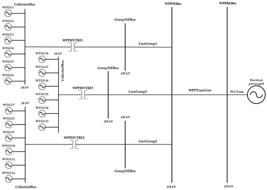
Figure 1.
Modern power grid system [27]. The component by the name electrical power grid represents the IEEE 9-bus power system.
In the figure, WTGU denotes the wind turbine generator unit, each connected to collector buses (Collector1Bus, Collector2Bus, and Collector3Bus). The WPPHVTRF represents the wind power plant high-voltage transformer, with WPPHVTRF1, WPPHVTRF2, and WPPHVTRF3 stepping up voltages from 24 kV collector buses to 230 kV transmission-level buses. The Group1SEBus, Group2SEBus, and Group3SEBus indicate the secondary side buses of the respective high-voltage transformers. The lines connecting these buses are designated as LineGroup1, LineGroup2, and LineGroup3, which transfer power toward the WPPSEBus (wind power plant sending-end bus). The WPPREBus (wind power plant receiving-end bus) represents the point of common coupling bus. The WPPTransLine stands for the wind power plant transmission line, while PCCTerm refers to the point of common coupling terminal where the WPP integrates with the external electrical power grid.
This system comprises essential components of a high-voltage transmission network, such as synchronous generators, transformers, transmission lines, loads, and busbars, enabling a realistic simulation of power system dynamics under both normal and fault conditions. Although a particular wind turbine generator unit (WTGU) is also selected for monitoring, the point of common coupling (PCC) of the modern power grid still serves as the main point of focus for the proposed monitoring and protection system. In the modern power grid of discussion, the PCC is the LSWPP receiving-end busbar (WPPREBus).
The modern power grid described above operates in two conditions, under initial load demand and increased load demand. The logic used for the simulation of these conditions is shown in Figure 2 [27].
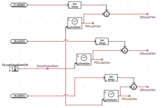
Figure 2.
Logic for load scheduler and direct proportionality of active and reactive power demand [27].
Load flow simulations were performed on the described system under initial and increased load demand conditions. The analysis focused specifically on the branch currents related to the protected busbar WPPREBus or simply PCC, and busbar voltages. The results of these simulations, recorded after the system reached a steady state, are presented in Table 1, Table 2, Table 3 and Table 4. Among them, the results in Table 2 are the same as the ones we obtained in our recent study in reference [27].

Table 1.
Branch currents recorded at steady-state under initial loading conditions for the modern power grid system.

Table 2.
Busbar voltages recorded on steady-state under initial load demand conditions for the modern power grid system [27].

Table 3.
Branch currents recorded at steady-state under increased loading conditions for the modern power grid system.

Table 4.
Busbar voltages recorded at steady-state under increased load demand conditions for the modern power grid system.
3. Monitoring and Protection System Design
3.1. Overview of the Proposed System
The monitoring and protection system used in this study is based on a low-impedance busbar current differential relaying system. This method was chosen for its advantages over other busbar current differential relaying systems. Reference [28] can be visited for an example of a low-impedance busbar current differential relaying system, and reference [29] for a detailed comparison of various types and their respective benefits and drawbacks.
The working principle of a differential protection system is as follows: if the differential current exceeds both the pick-up current and the product of the percentage slope (SLP) and the restraining current , the relay sends a TRIP signal (binary 1) to the circuit breaker (CB).
In summary, a trip signal is issued if > and × . is the pick-up current threshold. The relay works with secondary currents from current transformers (CTs), which compare the expected values. CTs on parallel feeders must have identical turn ratios to ensure accurate computation of secondary currents [30,31].
Nowadays, digital/numerical relays are used in monitoring and protection systems. One advantage of digital relays is their ability to determine phase angles even under severe CT saturation accurately. Proper relay function depends on accurately distinguishing between internal and external faults.
In the event of a through fault, the relay can temporarily block differential protection operating elements to avoid false trips. However, this method can delay trips during actual internal faults. To address this, directional detection elements are used. These determine the direction of fault current flow and enhance the ability of the relay to respond correctly, even during CT saturation [1,2]. For further information on CT saturation, see references [32].
Overall, Figure 3 presents the development process flowchart for the study. The flowchart summarizes the systematic stages followed in this study, including: modeling the modern power grid with an integrated large-scale wind power plant (LSWPP), selecting and configuring instrument transformers, implementing low-impedance busbar differential protection on the SEL-487B relay, integrating IEC 61850 GOOSE communication, and validating the complete system through real-time hardware-in-the-loop (HIL) testing on RTDS hardware. These stages are detailed in Section 2 (System Modeling), Section 3 (Protection System Design and Relay Configuration), Section 4 (HIL Setup and IEC 61850 Communication Integration), Section 5 (System Testing and Evaluation), and Section 6 (Results and Discussion).
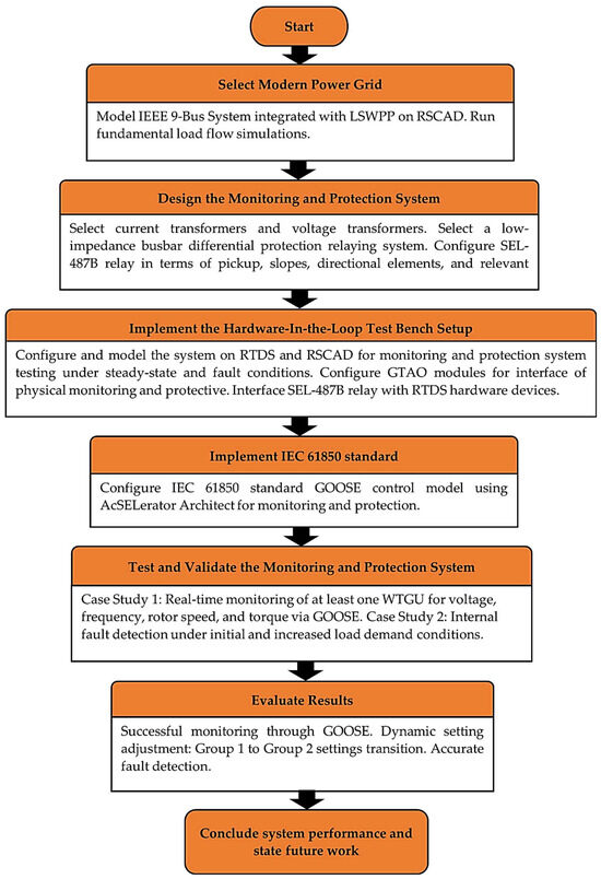
Figure 3.
Development process flowchart for the proposed IEC 61850-based monitoring and protection system.
3.2. Instrument Transformer Selection
Current transformers (CTs) were rated at 150% of the full-load current at the PCC (Bus2) to ensure reliable measurement and minimize CT saturation. As shown in Table 3, the branch current in LineDLoad1 (0.4530 kA) was the largest and approximately equal to the sum of Line24, Line12, and WPPLine currents, making it the basis for CT sizing. Accordingly, an 800:5 CT (160:1 turns ratio, 0.41 Ω burden) was selected in line with IEEE recommendations, and identical ratios were applied across all CTs to maintain differential protection accuracy. For voltage measurement, standard CVT parameters for 230 kV systems were adopted from RTDS Technologies, with only minor editing of signal names for mapping.
3.3. Configuration of SEL-487B Relay
The SEL-487B Relay was configured to implement a low-impedance busbar differential protection system at the PCC. Current transformer (CT) and voltage transformer (VT) inputs were mapped per phase to three differential elements (DIFF_R, DIFF_Y, DIFF_B), each processing four feeder currents (ILine12, ILine24, IDLoad1, IWPPLine). Differential operation was defined by the pickup threshold O87P and two percentage restraint slopes: Slope 1 for internal faults and Slope 2 for external faults. To enhance security under CT saturation, a directional element with a designated reference feeder and the 50DSP threshold provided supervision.
Adaptive protection was achieved through automatic switching between Group 1 and Group 2 settings, where Group 1 applied under normal load conditions and Group 2 under increased load. This ensured high sensitivity under stressed conditions while maintaining stability during external faults. Detailed settings, terminal aliasing, and QuickSet screenshots are provided in Appendix A.
Integration of the relay into the monitoring and protection framework followed the IEC 61850 standard, where Logical Nodes (LNs), GOOSE messaging, and communication mapping were applied to enable interoperability and real-time data exchange within the system.
Figure 4 [31] illustrates the modified logic of the red-phase differential element, showing four current inputs, the filtered differential path, directional supervision, and fault detection logic, while Table 5 summarizes the five conditions that must be satisfied for the instantaneous differential element (87RP) to assert, ensuring secure and dependable operation of the protection system.
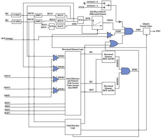
Figure 4.
Modified logic for busbar red phase differential element [31].

Table 5.
Conditions required for the operation of the instantaneous differential element (87RP), including differential, restraint, fault detection, directional, and supervision elements.
The SEL-487B Relay was configured to implement a low-impedance busbar differential protection system at the PCC in accordance with the IEC 61850 standard. Current transformer (CT) and voltage transformer (VT) inputs were mapped per phase to three differential elements (DIFF_R, DIFF_Y, DIFF_B), each processing four feeder currents (ILine12, ILine24, IDLoad1, IWPPLine). Differential operation was defined by the pickup threshold O87P and two percentage restraint slopes: Slope 1 for internal faults and Slope 2 for external faults. To ensure security under CT saturation, a directional element with a designated reference feeder and the 50DSP threshold provided additional supervision.
Adaptive protection was implemented through automatic switching between Group 1 and Group 2 settings, where Group 1 applied under normal load conditions and Group 2 under increased load. This ensured high sensitivity while maintaining stability during stressed operating conditions. Detailed configuration parameters, terminal aliasing, and QuickSet screenshots are provided in Appendix A for reproducibility, while only the essential configuration principles are summarized here.
3.4. Group 1 and Group 2 Switchover Logic Configuration
The adaptive protection framework automatically transitions from Group 1 to Group 2 settings when feeder currents increase under higher load demand, particularly when the wind power plant (WPP) contributes additional generation. This switchover is achieved by definite-time overcurrent elements configured to monitor key feeders.
If the measured current exceeds the set threshold of 0.55 A for any of the definite-time elements (50P10P, 50P11P, 50P12P), the corresponding relay wordbits (50P10RP, 50P11YP, 50P12BP) assert and, after the time delay, activate (50P10RT, 50P11YT, 50P12BT). Their activation triggers the Group 2 (SS2) settings, which remain in force until the relay front-panel pushbutton (PB5) is manually pressed to revert to Group 1 (SS1).
The implemented logic is illustrated in Figure 5, showing the switchover configuration in AcSELerator QuickSet. Detailed parameters, aliasing, and screenshots are provided in Appendix A for reproducibility.
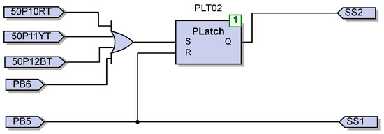
Figure 5.
Configuration of Group 1 to Group 2 switchover logic in AcSELerator QuickSet. The logic monitors feeder currents using definite-time overcurrent elements and initiates the transition to Group 2 settings when the threshold is exceeded.
4. Hardware-in-the-Loop Simulation Test Setup on Real-Time Simulation Computer-Aided Design 2.4
The proposed monitoring and protection system was validated in a hardware-in-the-loop (HIL) environment using the Real-Time Digital Simulator (RTDS) and RSCAD 2.4. The RTDS was interfaced with the SEL-487B busbar differential relay and SEL-751A feeder relay through GTAO analog output modules for CT and VT signals and GTFPI I/O channels for breaker control and status. This allowed device-level testing under realistic operating and fault scenarios without requiring a physical substation.
At the CSAEMS laboratory (CPUT), the testbench integrated simulated secondary signals with physical relays. Analog outputs from the RTDS represented CT and CVT signals of Bus2, while binary GOOSE messages coordinated protection actions. The setup enabled end-to-end evaluation of real-time monitoring, adaptive protection logic, and trip coordination.
Figure 6 shows the complete HIL setup, including the RTDS racks, GTAO/GTFPI modules, Omicron amplifiers, and SEL relays. This arrangement ensured scalable and accurate interfacing between simulation and hardware, replicating a transmission-level substation environment.
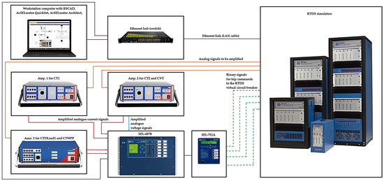
Figure 6.
Complete hardware-in-the-loop (HIL) test bench setup used for validating the proposed IEC 61850 standard-based monitoring and protection system, showing the interconnection of the RTDS simulator, GTAO/GTFPI I/O modules, Omicron CMS 156/356 voltage and current amplifiers, and the SEL-487B and SEL-751A protection relays.
Additional CT/CVT parameter configurations, GTAO mappings, and monitoring signal settings are provided in Appendix B.
Table 6 summarizes the selected electrical and mechanical signals from WTGU13 that were monitored via IEC 61850 logical nodes (MMXU) and published as GOOSE messages. The full IEC 61850 dataset mapping and logical node bindings used to publish WTGU13 signals are documented in Appendix C. These included voltages, currents, active/reactive power, frequencies, and rotor speed, ensuring comprehensive visibility of wind turbine performance under varying loading conditions.

Table 6.
Electrical and mechanical signals from WTGU13 monitored via IEC 61850 logical nodes (MMXU) and published as GOOSE messages.
5. System Testing and Evaluation
This section presents the validation of the IEC 61850-based monitoring and protection system using the HIL setup described earlier. The aim was twofold: first, to confirm that the system can monitor important electrical and mechanical signals at WTGU13 in real time through GOOSE communication, and second, to check the protection performance under both normal and stressed conditions. Two operating cases were considered: initial load demand and increased load demand as created by the load scheduler in Figure 2, discussed earlier in Section 2. For each case, monitoring was carried out at WTGU13, while the SEL-487B relay performance was verified through its differential protection records. The Group 1 and Group 2 settings (explained in Section 3.4) were applied, with Group 2 automatically activated once feeder currents exceeded the definite-time thresholds.
The system architecture was intentionally designed in a modular manner using standardized IEC 61850 standard Logical Nodes (LNs), GOOSE-based messaging, and structured ICD/SCD configuration files, enabling straightforward future expansion to additional feeder bays, busbar zones, or multivendor IEDs.
5.1. Case Study 1: Real-Time Monitoring
The monitoring chain involved the RTDS analog measurements, which were processed by the SEL-487B relay, modeled in the RSCAD FX IEC 61850 IED Configuration Tool (ICT) 2.2.1 as MMXU data objects, and published as GOOSE messages. At WTGU13, the monitored set (see Table 6) included per-unit (PU) voltage, phase currents, active and reactive power, per-phase frequencies, and rotor speed. These values helped to evaluate how the wind turbine generator unit behaved under different load conditions of the grid.
5.1.1. Real-Time Monitoring Under Initial Load Demand Conditions
At the initial loading level, the PCC bus voltages and feeder currents stayed within their steady-state values (Table 1 and Table 2), which created stable operating conditions for WTGU13. The monitored outputs from WTGU13 confirmed this: active power and reactive power remained steady, rotor speed showed only small variations around its set-point, and the three-phase frequencies were stable and well balanced. No dataset loss or delay was observed on the GOOSE stream, confirming that the publishing and subscription configuration was reliable. These results are presented in Figure 7 and Figure 8.

Figure 7.
WTGU13 monitored signals under initial load demand, captured on RSCAD FX Runtime: Meters 1−7 display terminal voltage (PU), line current (kA), active power (MW), reactive power (MVARs), red-phase frequency (Hz), and rotor speed (rad/sec and rpm).
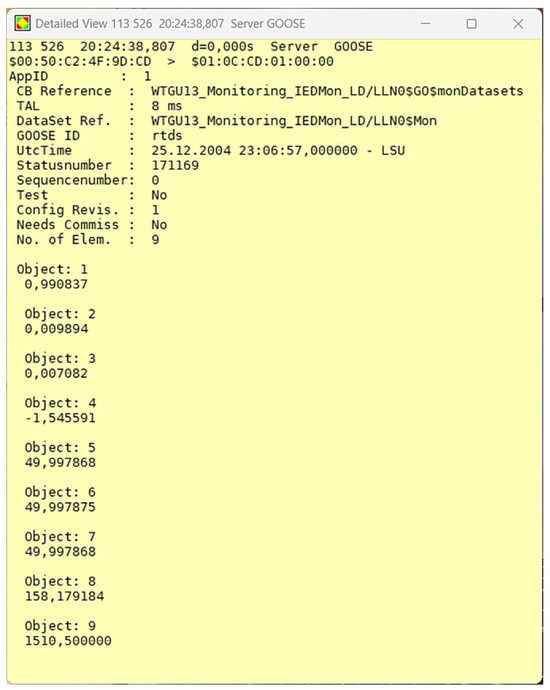
Figure 8.
WTGU13 monitored signals under initial load demand, captured via GOOSE: Objects 1−9 represent terminal voltage (PU), line current (kA), active power (MW), reactive power (MVARs), per-phase frequencies (R/Y/B), and rotor speed.
5.1.2. Real-Time Monitoring Under Increased Load Demand Conditions
When the scheduler gradually increased the load (Figure 2), the system currents rose and PCC voltages dropped slightly, as shown earlier in Table 3 and Table 4. Under these stressed conditions, the definite-time elements triggered the switchover to Group 2 settings in the relay. Monitoring at WTGU13 showed the expected response: active power increased to meet the new demand, reactive power rose proportionally to maintain the power factor, and rotor speed tracked the operating point without instability. The per-phase frequencies also remained within acceptable limits, showing that the wind turbine was able to maintain stable operation. Figure 9 and Figure 10 illustrate these monitoring results.

Figure 9.
WTGU13 monitored signals under increased load demand, captured on RSCAD FX Runtime: Meters 1−7 display terminal voltage (PU), line current (kA), active power (MW), reactive power (MVARs), red-phase frequency (Hz), and rotor speed (rad/sec and rpm).
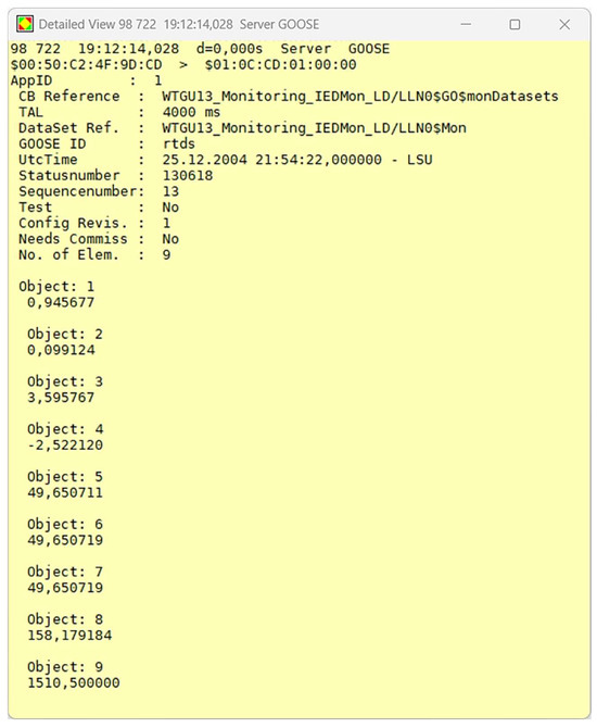
Figure 10.
WTGU13 monitored signals under increased load demand, captured via GOOSE: Objects 1−9 represent terminal voltage (PU), line current (kA), active power (MW), reactive power (MVARs), per-phase frequencies (R/Y/B), and rotor speed.
5.2. Case Study 2: Fault Detection and Protection
This part of the study focused on validating the fault detection and protection capability of the SEL-487B relay under both initial and increased load demand conditions. While real-time monitoring was carried out at WTGU13, the protection performance was evaluated at the PCC through the differential element records of the SEL-487B. All three-phase internal faults were introduced in each case, and the responses of the protection scheme were captured through waveform traces and binary outputs.
5.2.1. Fault Detection and Protection Under Initial Load Demand Conditions
The protection and monitoring system was initially tested under steady-state conditions at the nominal load demand to evaluate the accuracy of voltage and current signal measurements and to validate the monitoring and protection capabilities of the SEL-487B relay. Table 7 shows the operating and restraint currents results under initial load demand conditions.

Table 7.
Differential metering under initial load demand conditions.
An all three-phase internal fault was subsequently introduced, which was accurately detected by the SEL-487B, resulting in the issuing of a TRIP command. The correct operation was validated through waveform captures and binary signal traces, as shown in Figure 11 and Figure 12. The actual end-to-end fault clearance time recorded was 606.667 ms under these initial load conditions.
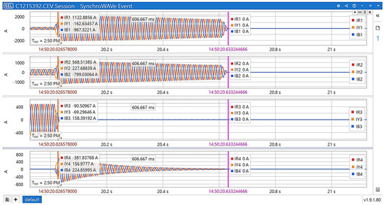
Figure 11.
Current waveforms recorded from the SEL-487B during an all three-phase internal fault under initial load demand. The corresponding HIL test achieved an end-to-end fault clearance time of 606.667 ms.
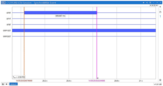
Figure 12.
Binary operation signals from the SEL-487B during the same all three-phase internal fault under initial load demand. The active GRP1SET signal indicates that Group 1 settings were applied.
5.2.2. Fault Detection and Protection Under Increased Load Demand Conditions
A subsequent test was conducted under steady-state conditions with increased load demand to further assess the reliability of signal measurements and to confirm the monitoring and protection functionality of the SEL-487B relay under elevated loading conditions. Table 8 shows the operating and restraint currents results under increased load demand conditions.

Table 8.
Differential metering under increased load demand conditions.
Another three-phase internal fault was simulated under the increased load demand condition. The SEL-487B again detected the fault and issued a TRIP signal. Figure 13 and Figure 14 present the relay logs and waveform recordings, confirming accurate and secure operation with no indication of maloperation or instability, even under increased load demand. The actual end-to-end fault clearance time recorded was 706.667 ms under these increased load conditions.
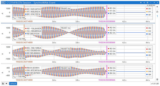
Figure 13.
Current waveforms recorded during an all three-phase internal fault under increased load demand, confirming correct detection and isolation. The corresponding HIL test achieved an end-to-end fault clearance time of 706.667 ms.
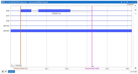
Figure 14.
Binary operation signals from the SEL-487B during the same all three-phase internal fault under increased load demand. The active GRP2SET signal confirms that Group 2 settings were applied.
The actual end-to-end fault clearance times recorded were 606.667 ms under initial load conditions and 706.667 ms under increased load conditions, which are acknowledged as the full relay-plus-breaker operation times in the hardware-in-the-loop setup, noting that field-deployed busbar protection schemes typically clear faults within approximately 100 ms.
The overall results from Figure 7, Figure 8, Figure 9, Figure 10, Figure 11, Figure 12, Figure 13 and Figure 14 are collectively discussed below to highlight the real-time monitoring performance and the fault detection speed of the developed system.
Figure 7, Figure 8, Figure 9 and Figure 10 present the real-time monitoring of selected electrical and mechanical signals from WTGU13, including three-phase voltages, line currents, active power, frequency, and rotor speed, transmitted from the RTDS model using IEC 61850 GOOSE messaging. All monitored values were made available online (IEC 61850 network) and were received with no packet losses recorded during steady-state or faulted operation, confirming the reliability and time-coherence of the monitoring framework.
Figure 11, Figure 12, Figure 13 and Figure 14 show the fault detection performance of the SEL-487B relay under both initial and increased load demand conditions. In the first case, the relay correctly and immediately detected an internal fault and issued a trip signal to clear the fault within 606.667 ms of the fault beginning. The associated GOOSE-based breaker operation confirmations were received after the trip command, demonstrating fast and deterministic end-to-end operation.
These results verify that the developed IEC 61850-based system provides accurate, low-latency real-time monitoring alongside dependable and fast protection performance, meeting typical requirements for transmission-level PCC applications.
6. Results and Discussion
This section discusses the results from two hardware-in-the-loop (HIL) case studies: (1) real-time monitoring of selected signals through the IEC 61850 standard, and (2) protection system performance under nominal and increased load conditions.
6.1. Case Study 1: Real-Time Monitoring of Selected Signals
The first case study focused on validating the real-time monitoring framework implemented using the IEC 61850 standard. Electrical and mechanical variables from WTGU13, including voltages, currents, active power, frequency, and rotor speed (as listed in Table 6), were published as GOOSE messages from the RTDS-simulated model to the physical relays and visualized through the IED interfaces. The results confirmed that these analog values were transmitted reliably and time-coherently, with no packet losses observed during the tests.
This case study demonstrated that the developed system can accurately stream and display real-time process measurements from a large-scale wind power plant model at a transmission-level PCC. It should also be noted that these same monitored signals (along with additional signals as needed) will be used in future research to implement a coordinated control framework that integrates monitoring, operation, and protection functions within the same IEC 61850-based platform.
6.2. Case Study 2: Protection Under Nominal and Increased Load Conditions
The second case study evaluated the performance of the protection system under both nominal and increased load demand conditions. At nominal load, the SEL-487B relay correctly restrained differential elements during normal operation and issued trips only when internal faults were applied. The measured operating and restraint currents were 0.32 PU and 4.38 PU, respectively, and the measured end-to-end fault clearance time was 606.667 ms from inception to breaker operation.
While field installations are typically expected to achieve full fault clearance within about 100 ms, the measured fault clearance times of 606.667 ms (initial load) and 706.667 ms (increased load) are acknowledged as the actual end-to-end operation times achieved by the developed system in the HIL environment.
Under increased load, the relay automatically switched from Group 1 to Group 2 settings based on the pre-defined load threshold. Under these conditions, the measured operating and restraint currents rose to 1.96 PU and 6.20 PU, respectively, while the relay maintained stability and selectivity. GOOSE-based breaker confirmation signals were received after the trip command. These results confirm the dependability, speed, and adaptability of the proposed protection system even under stressed loading conditions.
6.3. Communication Reliability and Real-Time Behavior
Throughout both case studies, the IEC 61850-based communication framework performed reliably. All analog and binary signals between the RTDS-simulated power grid and the physical SEL-487B and SEL-751A relays were exchanged using GOOSE messaging with no observed packet losses. This confirms the suitability of IEC 61850 standard peer-to-peer communication for time-critical monitoring and protection applications in renewable-integrated networks when implemented with proper LN mapping, dataset configuration, and Virtual Local Area Network (VLAN).
6.4. Comparative Contribution and Novelty
Most previous IEC 61850-based studies have concentrated primarily on protection functions and have treated monitoring either superficially or as offline data acquisition, often without real-time communication or hardware validation. For example, the study in [6] developed a backup subscription scheme using IEC 61850-9-2 sampled values; however, it did not implement real-time monitoring or adaptive logic. Another study in [8] focused on multivendor interoperability analysis, while the one in [14] introduced a composite sequence current technique evaluated only in offline simulation. Moreover, in [19], the HIL testing was also performed, but only for overcurrent protection, not for live process variable monitoring or busbar differential systems.
In addition, several review papers such as [4,5,23] extensively discussed IEC 61850-based protection schemes, digital substation architectures, and interoperability and certification challenges, respectively. However, they only provided conceptual and architectural overviews and did not include practical implementations, real-time hardware-in-the-loop validation, or detailed configuration procedures. While these reviews are valuable in highlighting gaps and trends, they offer no quantitative performance metrics or reproducible system designs.
A further limitation observed across nearly all the reviewed studies is the lack of transparency and reproducibility in their configuration processes. None of them provided complete step-by-step configuration details of their IEC 61850-based systems, which makes it difficult for other researchers or practitioners to replicate their setups. In contrast, the present work includes fully documented configuration procedures, such as detailed terminal aliasing tables, instrument transformer ratio settings, differential and directional element logic diagrams, and complete IEC 61850 dataset bindings to ensure transparency and reproducibility. These configuration procedures are presented in Appendix A, Appendix B and Appendix C. This level of detail has not been previously reported and represents a significant advancement over prior studies.
Additionally, most of the reviewed works used simplified test systems at the distribution level, whereas the present study was performed on a realistic transmission-level IEEE 9-bus system integrated with a large-scale wind power plant (LSWPP). This allowed evaluation of protection and monitoring behavior under conditions that are much closer to those found in actual high-voltage substations.
To clearly position the present work in relation to prior studies, Table 9 has been expanded to include the additional studies cited in the introduction and literature review, and compares them across key aspects such as real-time monitoring, real-time HIL validation, adaptive logic, CT/VT selection based on IEEE/IEC standards, configuration transparency, type of system used, and reported trip times.

Table 9.
Comparative summary of selected IEC 61850-based studies and the present work, highlighting their focus on real-time monitoring of analog signals, real-time HIL validation, use of adaptive logic, CT/VT selection based on IEEE/IEC standards, configuration transparency, and the type of system used (with this work uniquely using a transmission-level IEEE 9-bus system integrated with a large-scale wind power plant), alongside their reported trip times. ✓ and ✘ indicate whether the framework covered the items mentioned in the items or areas in columns 3–7.
As reflected in Table 9, most of the reviewed IEC 61850-based studies either concentrated on specific protection algorithms or on isolated aspects such as interoperability, communication modeling, or HIL-based testing, but none combined real-time monitoring of analog electrical and mechanical signals with protection validation on actual hardware, comprehensive configuration transparency, and a realistic transmission-level system model. Even the few studies that performed HIL testing, such as [9,10,18,19,24], focused only on protection behavior and used simplified distribution-level systems without providing reproducible configuration procedures.
This clearly demonstrates that the present work is the first to integrate a real-time IEC 61850-based monitoring framework, adaptive busbar differential protection, IEEE/IEC standards-based CT/VT selection, full configuration transparency, and a transmission-level test system into a single hardware-validated framework within a renewable-integrated grid, addressing a long-standing gap in the literature.
6.5. Scalability and Interoperability Considerations
It is acknowledged that the current HIL setup is based on an IEEE 9-bus system integrated with a single large-scale wind power plant, which represents a simplified test environment. However, the proposed framework was intentionally designed using modular IEC 61850 logical node structures, GOOSE-based peer-to-peer communication, and standardized ICD/SCD configuration files. These features inherently support the addition of multiple busbar zones, feeder bays, and PCCs without altering the underlying logic. Moreover, the use of vendor-neutral IEC 61850 data models enables future extension to multivendor intelligent electronic devices (IEDs), which is essential for realistic utility-scale substations. These design attributes indicate that the proposed framework can be scaled to larger and more complex networks in future studies.
7. Conclusions and Future Work
Based on the outcomes of this study, several future research directions are planned to further enhance and extend the developed IEC 61850-based monitoring and protection framework for large-scale renewable-integrated power systems.
It is acknowledged that the current fault clearance times (606.667 ms and 706.667 ms) are longer than typical field values (~100 ms) due to additional processing and communication delays in the hardware-in-the-loop setup, and future work will aim to reduce these times through optimization of the test platform and relay logic.
7.1. Adaptive Logic Refinement
Future work will focus on enhancing the adaptive protection logic implemented in the SEL-487B relay. This will include refining the automatic transition between Group 1 and Group 2 settings based on real-time system loading conditions and introducing automatic reversion to Group 1 settings once load returns to normal. This refinement will be tested through staged scenarios involving load variations, feeder switching, and temporary islanding/reconnection events to confirm its stability and responsiveness under dynamic network conditions.
7.2. Integration of Grid-Forming Inverters
The proposed framework will be expanded to incorporate grid-forming inverter (GFM) models within the RTDS-simulated network. This will allow assessment of how GFMs contribute to fault ride-through capability, system inertia, and frequency support during disturbances in renewable-integrated systems. Evaluating the protection system’s behavior in the presence of GFMs will help establish its applicability to future grids with high inverter-based resource penetration.
7.3. Cybersecurity and Resilience Testing
The current HIL testbed will be extended to evaluate the resilience of IEC 61850-based systems against cyberattacks, in line with IEC 62351 requirements. This will involve injecting faulty or delayed GOOSE and sampled value (SV) messages, message dropouts, and denial-of-service conditions into the communication layer to simulate compromised network scenarios. These experiments will help develop and validate cybersecurity countermeasures and intrusion detection strategies for substation automation systems.
7.4. Development of a Coordinated Monitoring–Operation–Protection (MOP) Control Method
Building on Case Study 1, which demonstrated real-time monitoring of electrical and mechanical signals through IEC 61850 GOOSE messaging, future work will develop a coordinated control framework that integrates monitoring, operation, and protection (MOP) functions on the same platform. The currently monitored signals (and additional required measurements) will be used to design automated control logic for supervising system operating states, issuing control actions, and coordinating protection schemes. This will transform the present system from a protection-only configuration into a comprehensive intelligent substation control solution for renewable-integrated power grids.
Author Contributions
Methodology, S.N.; Software, S.N.; Formal analysis, S.N.; Investigation, S.N.; Resources, A.K.R.; Data curation, S.N.; Writing – original draft, S.N.; Supervision, M.E.S.M.; Funding acquisition, M.E.S.M. and A.K.R. All authors have read and agreed to the published version of the manuscript.
Funding
This research received no external funding.
Data Availability Statement
Data and functional details presented in this study are available on request from the corresponding author.
Conflicts of Interest
The authors declare no conflict of interest.
Appendix A. Detailed Monitoring and Protection System Design

Table A1.
Aliasing of relay elements, current terminals, busbar zone elements, etc.
Table A1.
Aliasing of relay elements, current terminals, busbar zone elements, etc.
| Element Name | Original Description | Alias Name | Customized Description |
|---|---|---|---|
| I01 | Terminal 01 Current | IR1 | Red phase terminal current 1 |
| I02 | Terminal 02 Current | IY1 | Yellow phase terminal current 1 |
| I03 | Terminal 03 Current | IB1 | Blue phase terminal current 1 |
| I04 | Terminal 04 Current | IR2 | Red phase terminal current 2 |
| I05 | Terminal 05 Current | IY2 | Yellow phase terminal current 2 |
| I06 | Terminal 06 Current | IB2 | Blue phase terminal current 2 |
| I07 | Terminal 07 Current | IR3 | Red phase terminal current 3 |
| I08 | Terminal 08 Current | IY3 | Yellow phase terminal current 3 |
| I09 | Terminal 09 Current | IB3 | Blue phase terminal current 3 |
| I10 | Terminal 10 Current | IR4 | Red phase terminal current 4 |
| I11 | Terminal 11 Current | IY4 | Yellow phase terminal current 4 |
| I12 | Terminal 12 Current | IB4 | Blue phase terminal current 4 |
| BZ1 | Bus-Zone 1 | DIFF_R | Red phase differential element |
| BZ2 | Bus-Zone 2 | DIFF_Y | Yellow phase differential element |
| BZ3 | Bus-Zone 3 | DIFF_B | Blue phase differential element |
| P87R1 | Zone 1 instantaneous differential element picked up | 87RP | Red phase instantaneous differential element picked |
| P87R2 | Zone 2 instantaneous differential element picked | 87YP | Yellow phase instantaneous differential element picked |
| P87R3 | Zone 3 instantaneous differential element picked | 87BP | Blue phase instantaneous differential element picked |
| 87R1 | Zone 1 restraint differential element picked up | 87RT | Red phase instantaneous differential element tripped |
| 87R2 | Zone 2 restraint differential element picked up | 87YT | Yellow phase instantaneous differential element tripped |
| 87R3 | Zone 3 restraint differential element picked up | 87BT | Blue phase instantaneous differential element tripped |
| 87Z1 | Zone 1 differential element trip | 87RZ | Red phase differential element trip |
| 87Z2 | Zone 2 differential element trip | 87YZ | Yellow phase differential element trip |
| 87Z3 | Zone 3 differential element trip | 87BZ | Blue phase differential element trip |
| 87O1 | Zone 1 restraint differential operating current above O87P | 87ORP | Red phase restraint differential operating current above O87P |
| 87O2 | Zone 2 restraint differential operating current above O87P | 87OYP | Yellow phase restraint differential operating current above O87P |
| 87O3 | Zone 3 restraint differential operating current above O87P | 87OBP | Blue phase restraint differential operating current above O87P |
| FDIF1 | Zone 1 filtered restrained differential element picked up | FDIFRP | Red phase filtered restrained differential element picked up |
| FDIF2 | Zone 2 filtered restrained differential element picked up | FDIFYP | Yellow phase filtered restrained differential element picked up |
| FDIF3 | Zone 3 filtered restrained differential element picked up | FDIFBP | Blue phase filtered restrained differential element picked up |
| 50P10 | Terminal 10 definite-time overcurrent element | 50P10RP | Red phase instantaneous overcurrent element |
| 50P11 | Terminal 11 definite-time overcurrent element | 50P11YP | Yellow phase instantaneous overcurrent element |
| 50P12 | Terminal 12 definite-time overcurrent element | 50P12BP | Blue phase instantaneous overcurrent element |
| 50P10T | Terminal 10 definite-time overcurrent element timed out | 50P10RT | Red phase definite-time overcurrent element timed out |
| 50P11T | Terminal 11 definite-time overcurrent element timed out | 50P11YT | Yellow phase definite-time overcurrent element timed out |
| 50P12T | Terminal 12 definite-time overcurrent element timed out | 50P12BT | Blue phase definite-time overcurrent element timed out |
| SG1 | Settings group 1 active | GRP1SET | Group 1 settings active |
| SG2 | Settings group 2 active | GRP2SET | Group 2 settings active |

Table A2.
Mapping of specific current terminals to relevant busbar zone elements. DIFF_R, DIFF_Y, and DIFF_B represent differential elements for Red, Yellow, and Blue phases.
Table A2.
Mapping of specific current terminals to relevant busbar zone elements. DIFF_R, DIFF_Y, and DIFF_B represent differential elements for Red, Yellow, and Blue phases.
| Relay Terminals | Bus Zone Elements | ||||
|---|---|---|---|---|---|
| I01 | Terminal 01 current | IR1 (red phase terminal current 1) | BZ1 | Bus-Zone 1 | DIFF_R (red phase differential element) |
| I04 | Terminal 04 current | IR2 (red phase terminal current 2) | |||
| I07 | Terminal 07 current | IR3 (red phase terminal current 3) | |||
| I10 | Terminal 10 current | IR4 (red phase terminal current 4) | |||
| I02 | Terminal 02 current | IY1 (yellow phase terminal current 1) | BZ2 | Bus-Zone 2 | DIFF_Y (yellow phase differential element) |
| I05 | Terminal 05 current | IY2 (yellow phase terminal current 2) | |||
| I08 | Terminal 08 current | IY3 (yellow phase terminal current 3) | |||
| I11 | Terminal 11 current | IR4 (red phase terminal current 4) | |||
| I03 | Terminal 03 current | IB1 (blue phase terminal current 1) | BZ3 | Bus-Zone 3 | DIFF_B (blue phase differential element) |
| I06 | Terminal 06 current | IB2 (blue phase terminal current 2) | |||
| I09 | Terminal 09 current | IB3 (blue phase terminal current 3) | |||
| I12 | Terminal 12 current | IR4 (red phase terminal current 4) | |||
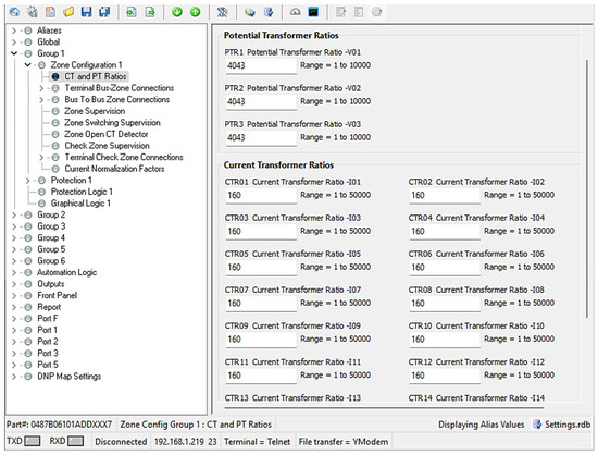
Figure A1.
SEL-487B Group 1 instrument transformer ratio settings.
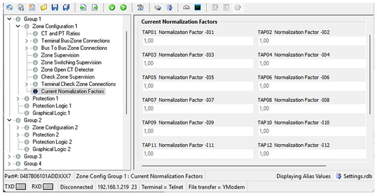
Figure A2.
SEL-487B Group 1 current normalization factor settings (auto-generated from CT ratio values).

Table A3.
Summarized configuration settings for SEL-487B Differential and Directional Elements.
Table A3.
Summarized configuration settings for SEL-487B Differential and Directional Elements.
| Group 1 | Group 2 | |||
|---|---|---|---|---|
| Differential and Directional Elements | Sensitive Differential Elements | E87SSUP Sensitive Differential Element Supervision | Y | Y |
| S87P Sensitive Differential Element Pickup (PU) | 10 | 10 | ||
| 87STPU 87S Timer Pickup Delay (Cyc) | 100 | 100 | ||
| Restrained Differential Elements | 087P Restrained Diff Element Pickup (PU) | 0.2 | 0.1 | |
| EADVS Advanced Settings | Y | Y | ||
| SLP1 Restrained Slope 1 Percentage | 20 | 15 | ||
| SLP2 Restrained Slope 2 Percentage | 60 | 50 | ||
| RTDI Incr Restrained Current Threshold (PU) | 0.2 | 0.1 | ||
| OTDI Incr Restrained Current Threshold (PU) | 0.2 | 0.1 | ||
| Check Zone Restrained Differential Elements | CZLP1 CZ Restrained Slope 1 Percentage | 20 | 15 | |
| CZLP2 CZ Restrained Slope 2 Percentage | 60 | 50 | ||
| CZRTDI CZ Incr Restrained Current Threshold (PU) | 0.2 | 0.1 | ||
| CZOPDI CZ Incr Restrained Current Threshold (PU) | 0.2 | 0.1 | ||
| Phase Directional Elements | 50DSP Dir Element O/C Supervision Pickup (PU) | 0.1 | 0.05 | |
| Trip Logic | TR01 Trip 1 | 87RT OR 87YT OR 87BT | ||
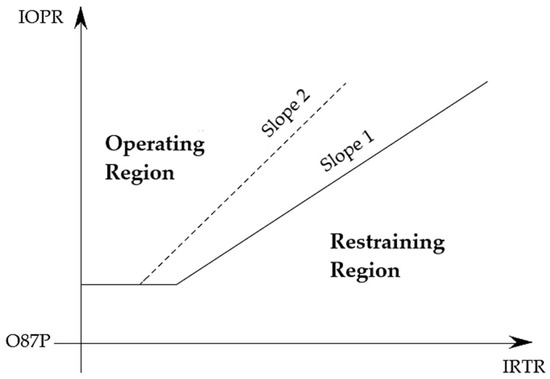
Figure A3.
Filtered differential element characteristic curve adapted from [31].
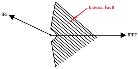
Figure A4.
Modified directional element logic. Adapted from [31].
Appendix B. Hardware-in-the-Loop Simulation Test Setup on Real-Time Simulation Computer-Aided Design 2.4
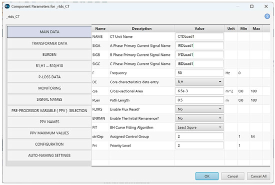
Figure A5.
Main data parameter settings for CTDLoad1. IRDLoad1, IYDLoad1, and IBDLoad1 are CT primary terminal current signals mapped from the line LineDLoad1 supplying the load.
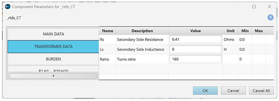
Figure A6.
Secondary winding series resistance and the primary winding turns ratio settings for CTDLoad1.
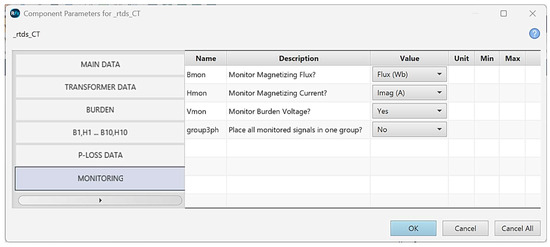
Figure A7.
Various current transformer analog signals are set for monitoring.
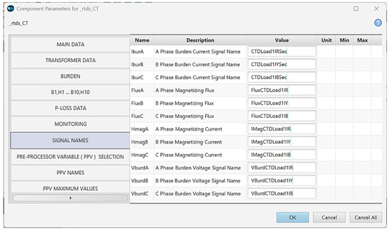
Figure A8.
Signal monitoring settings for CTDLoad1.
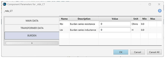
Figure A9.
Settings for the burden resistance of the CTDLoad1.
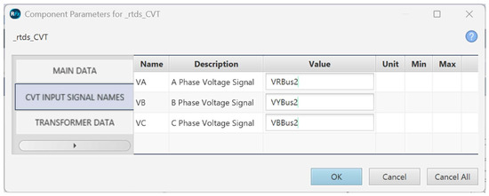
Figure A10.
Capacitor voltage transformer input signal names. VRBus2, VYBus2, and VBBus2 are voltage signals mapped from Bus2.
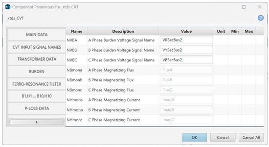
Figure A11.
Capacitor voltage transformer output signal names.
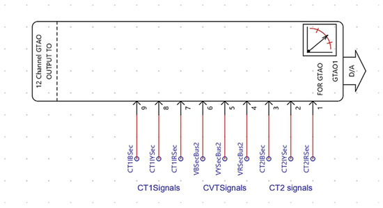
Figure A12.
GTAO1 configured for sampling CT1, CT2, and CVT signals. The input signals to GTAO1 are taken from the secondary sides of the CTs and CVT. Numbers 1–9 in the figure indicate the GTAO1 output channels activated and mapped to the corresponding CT and CVT signals.
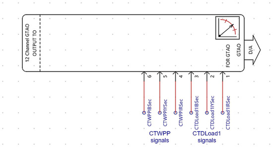
Figure A13.
GTAO2 configured for sampling CTWPP and CTDLoad1 signals. The input signals to GTAO2 are taken from the secondary sides of the CTs. Numbers 1–6 in the figure indicate the GTAO2 output channels activated and mapped to the respective CT signals.
Appendix C. IEC 61850 Standard Communication and HIL Setup
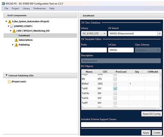
Figure A14.
Data model configuration. MMXU measurement Logical Node selected.
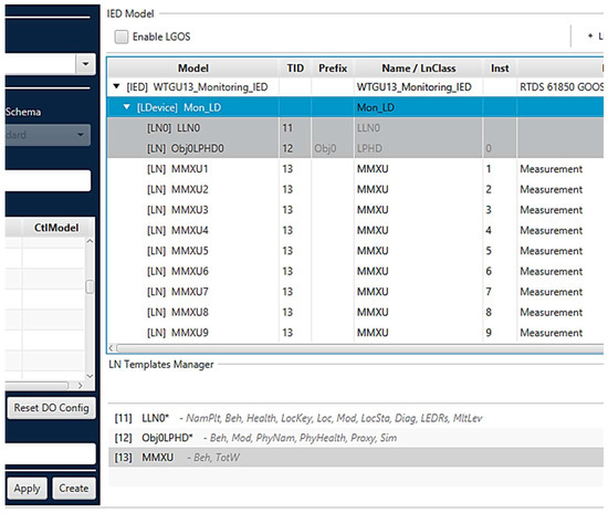
Figure A15.
Measurement Logical Node selected nine times for transport of nine signals to monitor from WTGU13.
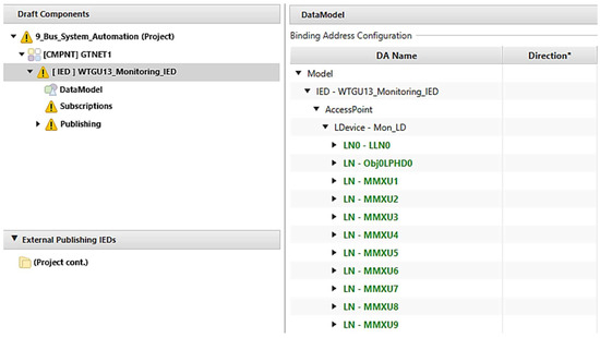
Figure A16.
Part 1. Binding of nine datasets to the selected signals to monitor from the WTGU13.
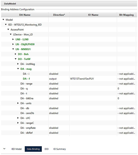
Figure A17.
Part 2. Binding of nine datasets to the selected signals to monitor from the WTGU13. WTG13TransVSecPUV is a signal for per-unit voltage measurement from the WTGU13 step-up transformer terminals.
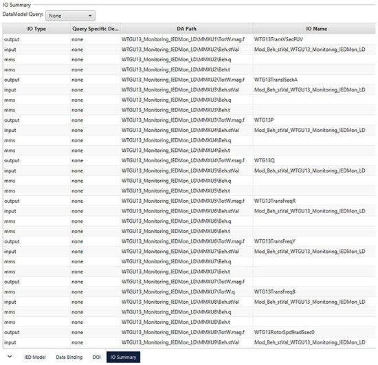
Figure A18.
Input output summary of all analog signals to measure from the wind WTGU13 bound onto nine selected MMXU Logical Nodes.
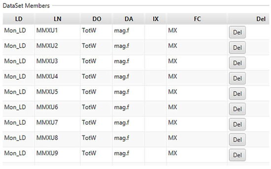
Figure A19.
Data attributes already bound or mapped with MMXU Logical Nodes.

Table A4.
List of SEL-487B Logical Nodes used.
Table A4.
List of SEL-487B Logical Nodes used.
| Data Source | Logical Node | Attribute | Comment | ||
|---|---|---|---|---|---|
| Element Name | Alias Name | Comment based on Original Element Name | Comment based on Alias Name | ||
| 87R1 | 87RT | D87RPDIF1 | Op.general | Zone 1 restraint differential element picked up | Red phase instantaneous differential element tripped |
| 87R2 | 87YT | D87RPDIF2 | Op.general | Zone 2 restraint differential element picked up | Yellow phase instantaneous differential element tripped |
| 87R3 | 87BT | D87RPDIF3 | Op.general | Zone 3 restraint differential element picked up | Blue phase instantaneous differential element tripped |
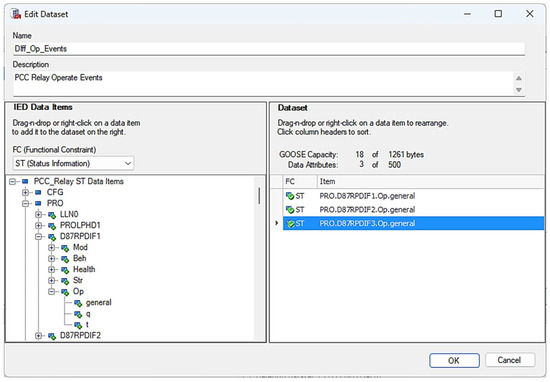
Figure A20.
Selection of datasets for SEL-487B.
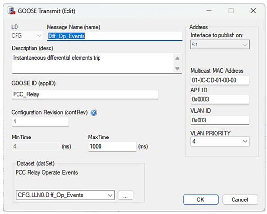
Figure A21.
Mapping of datasets for publishing from the SEL-487B.
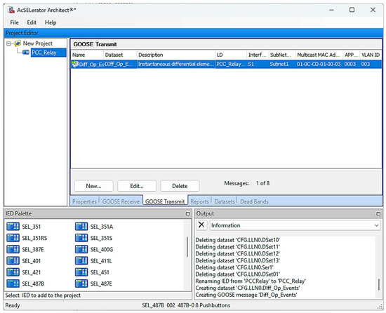
Figure A22.
Datasets already mapped for publishing from the SEL-487B.
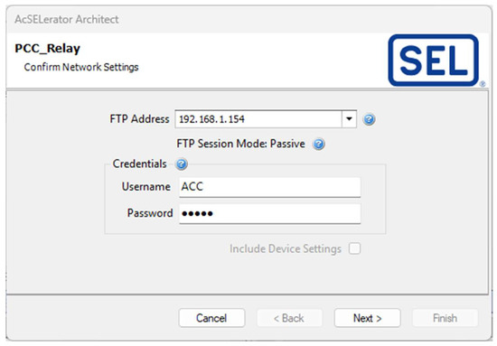
Figure A23.
Preparation for sending a Configured IED Description file to the SEL-487B.
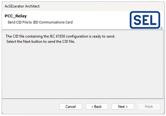
Figure A24.
Configured IED Description file ready to be sent to the SEL-487B.
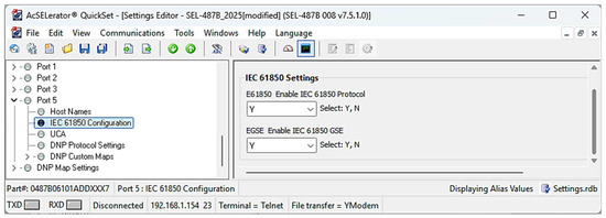
Figure A25.
Configuration and enabling of an IEC 61850 standard communication in an SEL-487B using AcSELerator QuickSet.
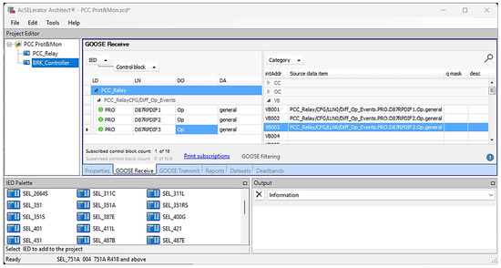
Figure A26.
Addition of the SEL-751A for circuit breaker control. Mapping of differential operating elements has been done through virtual bits VB001, VB002, and VB003.
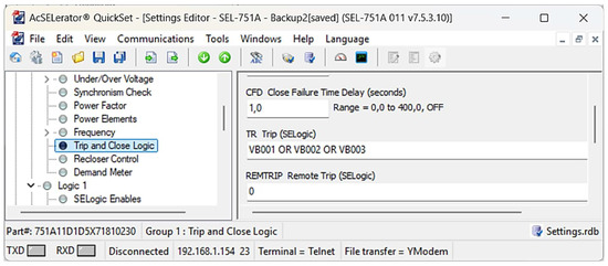
Figure A27.
Configuration of an SEL-751A for the use of virtual bits as a trip command for RTDS virtual circuit breaker logic operation.
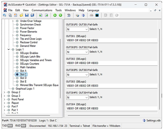
Figure A28.
Mapping of virtual bits to the physical outputs of the SEL-751A for physical interface with RTDS giga-transceiver front panel interface binary input terminals.
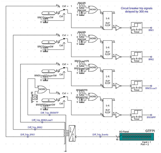
Figure A29.
Circuit breaker control logic for interface with SEL-751A device via giga-transceiver front panel interface card on RTDS.
References
- Guzman, A.; Qin, B.-L.; Labuschagne, C. Reliable busbar protection with advanced zone selection. IEEE Trans. Power Deliv. 2005, 20, 625–629. [Google Scholar] [CrossRef]
- Behrendt, K.; Costello, D.; Zocholl, S.E. Considerations for using high-impedance or low-impedance relays for bus differential protection. In Proceedings of the 2010 63rd Annual Conference for Protective Relay Engineers, College Station, TX, USA, 28 March–1 April 2010; IEEE: Piscataway, NJ, USA, 2010. [Google Scholar] [CrossRef]
- T. C. 57 International Electrotechnical Commission (IEC). “Communication Networks and Systems in Substations–Part 1: Introduction and Overview.” International Electrotechnical Commission (IEC), Geneva, p. 44. 2003. Available online: https://webstore.iec.ch/en/publication/6007 (accessed on 10 February 2025).
- Lima, D.A.C.; Bernardon, D.P.; Morais, A.P.; Oliveira, A.L.; Hokama, W.S.; Conceição, J.B.R.; Sartori, Â.F. Review of Bus Differential Protection Using IEC 61850. Energies 2022, 15, 9537. [Google Scholar] [CrossRef]
- Kumar, S.; Abu-Siada, A.; Das, N.; Islam, S. Reverse Blocking Over Current Busbar Protection Scheme Based on IEC 61850 Architecture. IEEE Trans. Ind. Appl. 2023, 59, 2225–2233. [Google Scholar] [CrossRef]
- Katoulaei, M.K.; Rahmani, A.; Høidalen, H.K.; Oleinikova, I.; Mork, B. Backup Subscription Scheme for Differential Protection using IEC 61850-9-2 Sampled Values. Energy Inform. 2024, 7, 110. [Google Scholar] [CrossRef]
- T. C. 57 International Electrotechnical Commission (IEC). “Communication Networks and Systems in Substations–Part 9-2: Specific Communication Service Mapping (SCSM) – Sampled Values over ISO/IEC 8802-3.” International Electrotechnical Commission (IEC), Geneva, p. 34. 2004. Available online: https://webstore.iec.ch/en/publication/5459 (accessed on 20 February 2025).
- Shangase, N.N.; Ratshitanga, M.; Mnguni, M.E.S. Interoperability Challenges in Multivendor IEC 61850 Devices for Parallel Power Transformer Differential Protection. Int. J. Electr. Electron. Eng. Telecommun. 2024, 13, 45–57. [Google Scholar] [CrossRef]
- Rathogwa, K.L.; Krishnamurthy, S. Hardware-in-the-loop simulation and testing of volts per hertz protection scheme for a generator over-excitation system. Int. J. Power Energy Convers. 2024, 15, 147–165. [Google Scholar] [CrossRef]
- Lim, J.-W.; Heo, K.-W.; Jeon, C.-O.; Kim, H.-S.; Jung, J.-H. Development of Power Hardware-in-the-Loop Simulation Test-bed to Verify LVDC Grid Stability Using Offline Damping Impedance Design. J. Electr. Eng. Technol. 2024, 19, 3297–3308. [Google Scholar] [CrossRef]
- Lehmal, C.; Zhang, Z.; Schürhuber, R. Benchmark Study of Transient Stability during Power-Hardware-in-the-Loop and Fault-Ride-Through capabilities of PV inverters. e+i Elektrotech. Informationstech. 2025, 142, 293–302. [Google Scholar] [CrossRef]
- Alasali, F.; El-Naily, N.; Loukil, H.; Omran, E.E.D.; Holderbaum, W.; Elhaffar, A.; Saidi, A.S. The Performance and Robustness of Power Protection Schemes for Grid-Connected PV Systems Under Varied Smart Inverter Controllers. Int. J. Energy Res. 2024, 2024, 6805410. [Google Scholar] [CrossRef]
- O’Malley, M.; Holttinen, H.; Cutululis, N.; Vrana, T.K.; King, J.; Gevorgian, V.; Wang, X.; Rajaei-Najafabadi, F.; Hadjileonidas, A. Grand challenges of Wind Energy Science—Meeting the Needs and Services of the Power System. Wind. Energy Sci. 2024, 2024, 2087–2112. [Google Scholar] [CrossRef]
- Jena, S.; Paladhi, S.; Pradhan, A.K. Bus protection in Systems with Inverter Interfaced Renewables using Composite Sequence Currents. Int. J. Electr. Power Energy Syst. 2022, 136, 107665. [Google Scholar] [CrossRef]
- Crăciun, O.; Florescu, A.; Munteanu, I.; Bratcu, A.I.; Bacha, S.; Radu, D. Hardware-In-the-Loop Simulation Applied to Protection Devices Testing. Int. J. Electr. Power Energy Syst. 2014, 54, 55–64. [Google Scholar] [CrossRef]
- Eissa, M.M. A New Digital Busbar Protection Technique Based on Frequency Information During CT Saturation. Int. J. Electr. Power Energy Syst. 2013, 45, 42–49. [Google Scholar] [CrossRef]
- Kong, Y.; Wu, Y.; Liang, Z.; Jia, R. Transient Energy-Based Ultra-High-Speed Unit Protection for Overhead Outgoing Lines in Inverter-Interfaced Renewable Energy Plants. Processes 2025, 13, 286. [Google Scholar] [CrossRef]
- Sparn, B.; Krishnamurthy, D.; Pratt, A.; Ruth, M.; Wu, H. Hardware-in-the-Loop (HIL) Simulations for Smart Grid Impact Studies. In Proceedings of the 2018 IEEE Power & Energy Society General Meeting (PESGM), Portland, OR, USA, 5–10 August 2018; IEEE Access: Piscataway, NJ, USA, 2018; pp. 1–5. [Google Scholar] [CrossRef]
- Sartori, Â.F.; de Morais, A.P.; Netto, U.C.; Lima, D.A.C.; Bernardon, D.P.; Hokama, W.S. Performance Analysis of Overcurrent Protection under Corrupted Sampled Value Frames: A Hardware-in-the-Loop Approach. Energies 2023, 16, 3386. [Google Scholar] [CrossRef]
- Zheng, T.; Cha, S.-T.; Kim, Y.-H.; Crossley, P.A.; Lee, S.H.; Kang, Y.C. Design and Evaluation of a Protection Relay for a Wind Generator Based on the Positive-and Negative-Sequence Fault Components. J. Electr. Eng. Technol. 2013, 8, 1029–1039. [Google Scholar] [CrossRef]
- Ali, I.; Hussain, S.M.S.; Tak, A.; Ustun, T.S. Communication Modeling for Differential Protection in IEC-61850-Based Substations. IEEE Trans. Ind. Appl. 2018, 54, 135–142. [Google Scholar] [CrossRef]
- Cabeza, L.F.; Verez, D.; Teixidó, M. Hardware-in-the-Loop Techniques for Complex Systems Analysis: Bibliometric Analysis of Available Literature. Appl. Sci. 2023, 13, 8108. [Google Scholar] [CrossRef]
- Ayello, M.; Lopes, Y. Interoperability Based on IEC 61850 Standard: Systematic Literature Review, Certification Method Proposal, and Case study. Electr. Power Syst. Res. 2023, 220, 109355. [Google Scholar] [CrossRef]
- Wang, J.; Pratt, A.; Prabakar, K.; Miller, B.; Symko-Davies, M. Development of an Integrated Platform for Hardware-In-the-Loop Evaluation of Microgrids Prior to Site Commissioning. Appl. Energy 2021, 290, 116755. [Google Scholar] [CrossRef]
- Bhattacharjee, T.; Jamil, M.; Alotaibi, M.A.; Malik, H.; Nassar, M.E. Multivendor-IEC-61850-Based Digital Substation. Energies 2022, 15, 1785. [Google Scholar] [CrossRef]
- Weedy, B.M.; Cory, B.J.; Jenkins, N.; JEkanayake, B.; Strback, G. Electric Power Systems, 5th ed.; Wiley: Hoboken, NJ, USA, 2012. [Google Scholar] [CrossRef]
- Nomandela, S.; Mnguni, M.E.S.; Raji, A.K. A Case Study on the Validation of Renewable Energy Grid Code Compliance for a Large-Scale Wind Power Plant Grid-Connected Mode of Operation in Real-Time Simulation. Appl. Sci. 2025, 15, 5521. [Google Scholar] [CrossRef]
- Nomandela, S.; Mnguni, M.; Raji, A. Busbar Differential Protection System Testing Based on Practical Considerations Using Real-Time Digital Simulator Hardware-In-the-Loop Technique. In Proceedings of the 2024 6th International Conference on Electrical Engineering and Control Technologies (CEECT), Shenzhen, China, 20–22 December 2024; IEEE: Piscataway, NJ, USA, 2024; pp. 359–363. [Google Scholar] [CrossRef]
- Andrichak, J.G.; Cardenas, J. Bus Differential Protection. In Proceedings of the Twenty Second Annual Western Protective Relay Conference, Spokane, WA, USA, 24 October 1995. [Google Scholar]
- C37.110-2007; IEEE Guide for the Application of Current Transformers Used for Protective Relaying Purposes. IEEE: Piscataway, NJ, USA, 2008.
- Schweitzer Engineering Laboratories. SEL-487B-1 Bus Differential and Breaker Failure Relay Instruction Manual; Schweitzer Engineering Laboratories: Pullman, WA, USA, 2018; p. 718. [Google Scholar]
- Uddin, S.; Bapary, A.; Thompson, M.; McDaniel, R.; Salunkhe, K. Application Considerations for Protecting Transformers with Dual Breaker Terminals. In Proceedings of the 45th Annual Western Protective Relay Conference, Spokane, WA, 16–18 October 2018; pp. 1–25. [Google Scholar]
Disclaimer/Publisher’s Note: The statements, opinions and data contained in all publications are solely those of the individual author(s) and contributor(s) and not of MDPI and/or the editor(s). MDPI and/or the editor(s) disclaim responsibility for any injury to people or property resulting from any ideas, methods, instructions or products referred to in the content. |
© 2025 by the authors. Licensee MDPI, Basel, Switzerland. This article is an open access article distributed under the terms and conditions of the Creative Commons Attribution (CC BY) license (https://creativecommons.org/licenses/by/4.0/).