Abstract
As lunar exploration missions advance, the need for safe and sustainable in situ energy systems has become increasingly critical. This study investigates the thermoelectric performance of Bi2Te3-based thermoelectric materials under the natural temperature variations on the lunar surface, aiming to illustrate the potential of thermoelectric generation technology in power supply for a crewed moon base. A numerical approach was employed to assess the energy conversion behavior and optimize the geometric design of a thermoelectric module couple consisting of a P-leg and N-leg. The results indicate that Bi2Te3-based modules exhibit promising functionality under cryogenic conditions, highlighting their potential as an in situ power source during the long lunar night. Furthermore, geometric optimization was shown to significantly enhance the overall thermoelectric performance. The present study illustrates that TEG technology offers a viable pathway toward reliable energy generation in extreme lunar environments, supporting future mission sustainability.
1. Introduction
The establishment of a permanent lunar human outpost has grown into a widely shared international aspiration [1,2,3]. Through the Artemis program, the United States aims to achieve a crewed lunar landing by 2026, with plans to subsequently establish a sustainable human presence on the Moon’s surface [2,4]. Meanwhile, China has outlined an ambitious lunar exploration road-map, targeting its first crewed Moon landing in 2029 as part of the International Lunar Research Station (ILRS) in collaboration with Russia and other partners [5]. A permanent moon base seems within range. However, key technological advancements for lightweight, reliable, and cost-effective energy generation are imperative [4], to support the transmission of information, satellite navigation, life maintenance, resource exploitation and other essential energy supplies [6,7]. Since each lunar day and night lasts approximately 14.77 Earth days [7], the traditional approach of using solar panels with batteries faces a major limitation due to massive energy storage demands [8]. Thermoelectric generators (TEGs) offer a promising power generation solution for lunar bases [9]. Their operation relies on the thermoelectric effect, enabling the direct conversion of thermal energy into electricity. Unlike conventional heat engine cycles, TEGs contain no moving parts or kinetic components, resulting in superior reliability, operational stability, and structural robustness [7,9,10,11]. These attributes provide TEGs with distinct advantages for use in the challenging lunar environment [12].
Cold energy harvesting by thermoelectric generator module (TEM) provides a full chain utilization of the whole temperature zone, and has the characteristics of feasibility and large-scale utilization [13,14]. Furthermore, the efficiency of cold energy conversion with TEG is better than that of waste heat conversion [15]. During the lunar night, the surface temperature of the Moon drops to approximately 90 K, whereas the thermal conductivity of lunar regolith is extremely low, with a value of only ~0.01 W/(m·K), at depths greater than ~0.4 m, the regolith maintains a nearly constant temperature of around 250 K [16,17,18]. This creates a natural source of cold energy with a gradient of approximately 160 K between the surface and the deeper regolith layer [19,20]. If this inherent cold energy can be effectively harnessed for electricity generation, it could largely overcome the power supply challenges faced by equipment during the extended lunar night [21]. Thermoelectric generator (TEG) technology has emerged as a promising method for generating power from the cold energy available during the lunar night, despite challenges such as low thermoelectric conversion efficiency and a shortage of high-performance thermoelectric materials (TMs) suitable for cryogenic environments [22].
Published papers on TE module performance at the temperature gradient from room temperature to cryogenic temperature are scarcely available [23,24]. The maximum conversion efficiency of 1.76% at the temperature range of 200–300 K was measured for TE module with N-type BiSb-based and P-type MgAgSb-based materials [14]. Lobunets [14] reported a maximum power output around 25 W and conversion efficiency of 8.85% for a single thermoelectric module consisting of 263 Bi2Te3-based P-N couples. This represents the highest performance documented in published studies to date for a TEM under cryogenic temperature conditions. Kambe et al. [23] reported a maximum power output of 8.6 W from a TEM with dimension of 40 × 35 × 1 mm3, fabricated using conventional BiTe materials, under a temperature difference of 210 K and the hot-side temperature of 298 K. Sidorenko et al. [25] studied thermoelectric properties of Bi0.91Sb0.09 extruded crystals and single crystals were studied over the entire temperature range of 77–200 K, with an averaged value of thermoelectric figure of merit (ZT) around 0.6. Using improved extrusion technology for bismuth antimony tellurides, new extruded TEMs were developed with increased thermoelectric figure of merit around 0.7–0.8 [26]. When doped appropriately, the material CsBi4Te6 exhibits a high thermoelectric figure of merit below room temperature (ZTmax = 0.8 at 225 K) [27]. Enhanced cryogenic thermoelectric ZT with an average value as high as 0.8 from 180 to 300 K was obtained for Bi0.5Sb1.5Te3 by carrier optimization [28].
The integration of TEGs with in situ resource utilization (ISRU) systems offers a promising solution for providing continuous power during the lunar night [7]. However, harnessing the abundant cold energy of the lunar environment for power generation remains a significant challenge in establishing a crewed lunar base [29]. Previous reviews on TMs indicate a notable research gap in the application of TEGs for cold energy utilization. This study focuses on the heat-to-electricity conversion performance of BiTe-based thermoelectric materials under lunar conditions. Numerical simulations using COMSOL Multiphysics 6.2 are employed to analyze the thermoelectric behavior of BiTe-based materials throughout the entire lunar diurnal cycle. Based on these simulations, the potential of TEG technology for lunar in situ energy utilization is comprehensively evaluated.
2. Methodology
2.1. Geometric TEM Model
A typical TEM consists of multiple P-type and N-type semiconductor couples connected electrically in series and thermally in parallel, all encapsulated between two highly thermally conductive ceramic plates. In this study, a single couple is analyzed for simplicity, neglecting the influence of the connecting adhesives. The geometric configuration of the thermoelectric couple is illustrated in Figure 1a, with the corresponding computational mesh presented in Figure 1b. Both the P-type and N-type legs exhibit identical geometric dimensions. A detailed summary of the dimensional parameters and thermoelectric properties for each leg is provided in Table 1. Both the P-leg and the N-leg are identical, with dimensions of 1.7 × 1.7 × 1.8 mm3, which are the same with that of Luo et al. [30] for validation of the present numerical method. The P-leg and N-leg are connected by a 0.2 mm wide copper interconnecting plate.
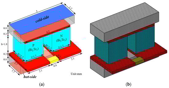
Figure 1.
Schematic of a 3D thermoelectric couple model: (a) geometric configuration; (b) computational mesh.

Table 1.
P-leg and N-leg specifications used in the present study.
2.2. Properties of TE Materials
Table 1 summarizes the geometric and material properties of the thermoelectric (TE) couple. For clarity, the Seebeck coefficient, electrical conductivity, thermal conductivity, and figure of merit (ZT) of the thermoelectric materials within the temperature range of 300–500 K are presented in Figure 2. It should be noted that the ZT value of the P-leg material exhibits a decreasing trend above 350 K, primarily due to an increase in thermal conductivity and a decrease in electrical conductivity. In contrast, the ZT value of the N-leg material decreases gradually with temperature. Both materials demonstrate relatively high ZT values at lower temperatures, which enhances their performance under cryogenic conditions.
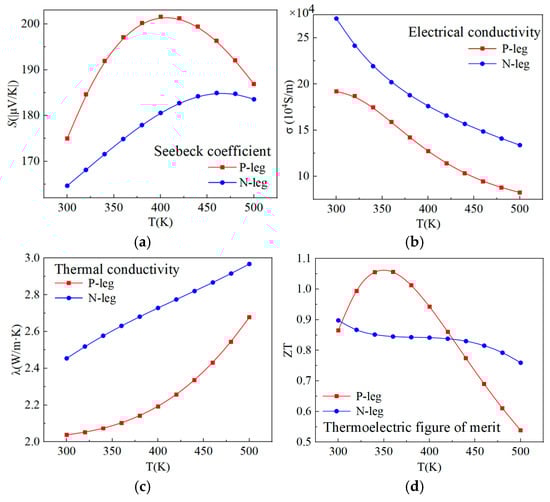
Figure 2.
Thermoelectric properties of the TMs: (a) Seebeck coefficient; (b) Electrical conductivity; (c) Thermal conductivity; (d) Thermoelectric figure of merit.
2.3. Governing Equations
The conservation equations and physical laws of TEGs are as follows [30]:
where and represent the current density vector and Seebeck coefficient, respectively. The local current density is given by
The power output of the TEG is
where RL is the load resistance. The current, I, is given by the Ohm’s Law:
The thermoelectric conversion efficiency of the TEG is
The maximum power output (Pmax) and maximum conversion efficiency (ηmax) can be obtained by altering the load resistance [30].
2.4. Computational Setup
The physics interfaces and corresponding settings employed in the simulation are summarized in Table 2, which includes the Heat Transfer interface with initial temperature, fixed temperature boundaries, and thermal insulation conditions; the Electric Current interface incorporating initial current and electrical insulation settings; and the Multiphysics couplings for thermoelectric effects and electromagnetic heating. The numerical solutions are obtained using the Finite Element Method (FEM).
Table 2.
Numerical calculation scheme.
Due to the very slow temperature variation throughout the lunar diurnal cycle, transient processes have a negligible influence on thermoelectric performance. Therefore, the entire cycle was discretized into multiple time segments, each assumed to have a constant temperature. The overall performance of the thermoelectric unit over the full cycle is approximated by evaluating its behavior within each individual segment. Accordingly, all simulations in this study were carried out under steady-state assumptions, and transient effects were neglected.
2.5. Grid Independence Validation
As shown in Figure 1b, a structured grid consisting predominantly of hexahedral elements is employed for the TEG couple. A grid independence study was conducted to determine the suitable mesh size for numerical simulations. The steady-state output performance of the TEG couple under different mesh sizes was evaluated, with the load resistance set to 0.01 Ω; the corresponding results are presented in Table 3. When the mesh size is reduced to 0.1 mm, the relative error in output power drops to 0.02%, indicating sufficient numerical accuracy. Accordingly, a mesh size of 0.1 mm was selected for all subsequent simulations to balance computational efficiency and model precision.
Table 3.
Steady-state output performance of a TEG couple with different mesh numbers.
3. Simulation Results
3.1. Model Verification
Figure 3a presents the numerical simulation results of the output power for a single TEM couple under a hot-side temperature of Th = 500 K, a cold-side temperature of Tc = 300 K, and varying external load resistances. The corresponding results from Luo et al. [30] are also included for comparison. The maximum prediction error relative to Luo et al.’s data is less than 0.7%, indicating high accuracy of the current numerical approach. Figure 3b displays the temperature and electrical potential contours from both the present study and Ref. [30], which exhibit strong agreement and further validate the correctness of the present methodology.
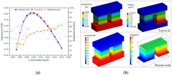
Figure 3.
Comparison of the numerical results of present work and [30]: (a) output power; (b) temperature and electrical potential contours.
3.2. Thermoelectric Performance of a Single TEM Couple
Figure 4 illustrates the thermoelectric performance of the TEM couple under various cryogenic temperature gradients. The cold side of the ceramic plate is held constant at 90 K, representing the minimum temperature encountered on the lunar surface. The hot side temperature varies from 248 K (corresponding to the stable temperature layer of lunar regolith) to 400 K.
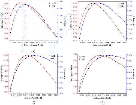
Figure 4.
Performance of a single couple under constant Tc = 90 K and varying Th: (a) Th = 248 K; (b) Th = 300 K; (c) Th = 350 K; (d) Th = 400 K.
Figure 4a shows the performance under the maximum temperature difference of 158 K during the lunar night. The maximum output power and thermoelectric conversion efficiency under these conditions are 0.08 W and 3.76%, respectively. As the hot side temperature increases to 300 K, resulting in a temperature difference of 210 K, the thermoelectric performance shows significant improvement: the maximum output power rises by 75%, reaching 0.14 W, and the conversion efficiency increases by 37.3%, reaching 5.17%. This enhancement is attributed to the rise in the dimensionless figure of merit (ZT) with increasing temperature. When the hot side temperature reaches 400 K, the output power and efficiency further increase to 0.28 W and 7.48%, respectively. The external load resistance corresponding to the maximum power and efficiency remains. The load resistances corresponding to both maximum power and efficiency varies slightly with the increase in hot-side temperature.
Figure 5 shows the output power and electrical potential as functions of electric current under the temperature differences presented in Figure 4. The output power exhibits a linear relationship with the current. As the hot-side temperature increases from 248 K to 400 K, the current at which maximum power output occurs rises from 3 A to 4.8 A, while the corresponding open-circuit electrical potential increases from approximately 36 mV to 72 mV.
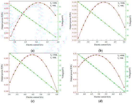
Figure 5.
I-A and I-W curves of a single couple under constant Tc = 90 K and varying Th: (a) Th = 248 K; (b) Th = 300 K; (c) Th = 350 K; (d) Th = 400 K.
Figure 6 illustrates the maximum output power and thermoelectric conversion efficiency of a single TEM couple under conditions of constant hot-side temperature and varying cold-side temperature. Both parameters decrease as the cold-side temperature increases, owing to the corresponding reduction in temperature difference. Nonetheless, the couple retains its power generation capability across a broad range of temperature gradients. This feature provides TEG technology with a notable advantage over other energy conversion methods for in situ energy utilization on the Moon, as it can effectively exploit the natural temperature variations present in the lunar environment.
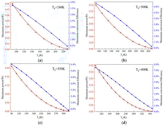
Figure 6.
Maximum output power and thermoelectric conversion efficiency of a single couple under constant Th and varying Tc from 90 K to 210 K. (a) Th = 248 K; (b) Th = 300 K; (c) Th = 350 K; (d) Th = 400 K.
During the lunar night, if energy storage devices are employed to maintain an elevated hot-side temperature, the thermoelectric performance can be enhanced significantly. As the hot-side temperature increases from 248 K to 400 K, both the maximum output power and thermoelectric conversion efficiency of a single TEM couple double, demonstrating considerable application potential for TEG technology under lunar conditions. The highest output power reaches 0.278 W, implying that a TEM comprising 200 couples could theoretically achieve a maximum output power of 55.6 W at Th = 400 K and Tc = 90 K.
As shown in Figure 4 and Figure 6, both the output power and thermoelectric conversion efficiency remain below 10%, which represents a major limitation of TEG technology in the lunar environment—a challenge also observed under conventional conditions. This performance constraint is primarily due to the relatively low ZT values (0.4–0.6) at cryogenic temperatures. The key to improving performance lies in enhancing the ZT value through the optimization of thermoelectric materials and fabrication techniques. Achieving a ZT value greater than 1 would significantly increase the applicability of TEG for power generation on the Moon.
3.3. Geometry Optimization
An analysis was conducted to examine the influence of geometric dimensions on the thermoelectric performance of a thermoelectric module (TEM) couple. The cross-sectional areas of both the P-type and N-type legs were varied from 1.0 × 1.0 mm2 to 2.0 × 2.0 mm2, while the leg height was adjusted between 1.5 mm and 2.0 mm. The numerical methodology and mesh generation for the computational domain were consistent with the approach described in Section 3.2 for a TEM couple with leg dimensions of 1.7 × 1.7 × 1.8 mm3.
As shown in Figure 7, under a constant temperature difference, increasing the cross-sectional area of the legs leads to a rise in the maximum output power. However, both the maximum thermoelectric conversion efficiency and the maximum power flux (defined as the maximum output power per unit cross-sectional area) decrease slightly. This decline is attributed to the corresponding increase in the electrical resistance of the couple. Consequently, the cross-sectional area has only a minor effect on the overall performance of the TEM couple from the perspective of power capacity. It should be noted that the results presented in Figure 7 were obtained under a constant temperature difference across the legs—a condition that may be difficult to achieve in practice. In real applications, a reduction in cross-sectional area could alter the temperature gradient along the legs, which in turn may significantly affect the thermoelectric performance.
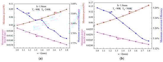
Figure 7.
Effect of cross-sectional area on thermoelectric performance of a single couple under constant Th and Tc. (a) Th = 248 K, Tc = 90 K; (b) Th = 300 K.
Figure 8 shows the simulated results of the maximum output power and maximum thermoelectric conversion efficiency of a TEM couple as functions of leg height under a constant temperature difference. In response to increasing leg height, the maximum output power and conversion efficiency demonstrate opposite behaviors; the former diminishes concurrently as the latter is enhanced. This behavior occurs because greater leg height reduces heat flux through the module, yet the output power declines only marginally. Consequently, as shown in Figure 8a, the overall conversion efficiency improves, rising from 3.73% to 3.82% as the leg height increases from 1.5 mm to 2.0 mm under constant temperature difference.
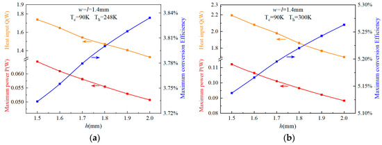
Figure 8.
Effect of the leg height on thermoelectric performance of a single couple under constant Th and Tc. (a) Th = 248 K, Tc = 90 K; (b) Th = 300 K. The arrows indicate the corresponding coordinate axis of the curve.
As indicated in Figure 8, when the hot side temperature increases from 248 K to 300 K, a significant improvement in performance is observed. The maximum output power rises from 0.064 W to 0.112 W for the leg height of 1.5 mm, while the maximum conversion efficiency increases from 3.83% to 5.26% for the leg height of 2.0 mm. This enhancement in output power is attributed to the increased heat flux resulting from the larger temperature difference. These results suggest that integrating an energy storage system to raise the hot side temperature during the lunar night could be an effective way to improve TEM performance.
3.4. Performance of a TEM Couple over a Lunar Diurnal Cycle
The lunar surface experiences extreme diurnal temperature variations, ranging from approximately 90 K to 400 K. These fluctuations, combined with the relatively stable temperature of the subsurface regolith layer, cause significant changes in the thermoelectric performance of a thermoelectric module (TEM). To assess the feasibility of thermoelectric generator (TEG) technology for lunar power systems under realistic conditions, the performance of a TEM couple was simulated over a full diurnal cycle based on the methodology in Section 3.3. The couple uses P-type and N-type legs with the same dimensions of 1.4 × 1.4 × 1.6 mm3. This geometry offers an optimized balance between thermoelectric efficiency and mechanical durability.
Figure 9 illustrates the thermoelectric performance of the TEM couple over a diurnal cycle equivalent to approximately 30 Earth days. Under the natural temperature gradient of the lunar environment and the influence of the isothermal regolith layer, the couple demonstrates relatively strong performance, particularly during the lunar night, where it operates stably and maintains high thermoelectric conversion efficiency and power output. Around 75% and 70% of the diurnal cycle, the efficiency exceeds 3.0% and the maximum output power surpasses 0.03 W, respectively. Figure 10 presents the cumulative electrical energy generated over one full diurnal cycle, totaling 28 W·h. This result implies that a TEM comprising 200 such couples would produce approximately 5.6 kW·h of electricity, a very considerable output for a TEM device measuring 40 × 40 × 4 mm3. If an energy storage device is employed, raising the temperature of the isothermal layer to 400 K, the accumulated energy output of the couple and the TEM can be significantly increased, reaching 60 W·h and 12 kW·h, respectively.
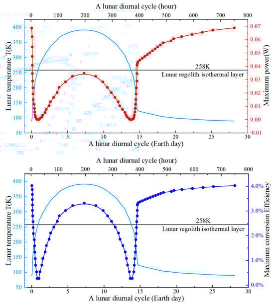
Figure 9.
Maximum output power and conversion efficiency of a single couple over a diurnal lunar cycle. The light blue line represents the lunar surface temperature.
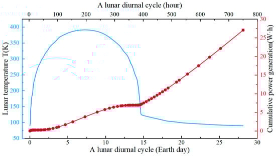
Figure 10.
Cumulative output power of a single couple over a diurnal lunar cycle. The light blue line represents the lunar surface temperature.
4. Discussion
The simulation results presented in Section 3 demonstrate that TEG technology exhibits significant application advantages for in situ power generation on the lunar surface. The natural temperature difference between the lunar regolith isothermal layer and the environment provides an essential prerequisite for the implementation of TEG technology. Especially during the lunar night, the temperature difference between the isothermal layer and the lunar surface environment exceeds 150 K for almost the entire period, which ensures stable and highly efficient operation of the TEG system. Moreover, power supply during the lunar night phase is particularly challenging: photovoltaic technology ceases to operate entirely, and relying solely on energy storage to meet power demands throughout the approximately 15-Earth-day-long lunar night is practically infeasible. The strong performance of TEGs during the lunar night effectively compensates for the limitations of photovoltaics. When combined with photovoltaic power generation during the lunar daytime, TEG technology offers a viable solution for continuous and reliable energy supply over the entire day-night cycle on the lunar surface.
At present, the primary bottleneck for applying TEG technology to lunar power supply remains the thermoelectric materials (TEMs). Their thermoelectric performance in low-temperature ranges is inferior to that in other temperature zones. Enhancing the thermoelectric properties of these materials under the extremely cold conditions on the lunar surface is therefore crucial. Based on this, another key technical challenge is the development of highly efficient heat exchange technologies suitable for the extreme environmental conditions on the Moon. Such technologies would enable TEG systems or devices to maintain the largest possible temperature difference across the TEM, while minimizing thermal resistance in every heat transfer pathway within the system.
Additionally, the modification of lunar regolith has emerged as another critical focus. Upon processing the lunar regolith to enhance its thermal conductivity, it can serve as a high-quality heat source during the lunar night, thereby significantly enhancing the performance of TEG systems.
5. Conclusions
With the accelerating progress of lunar exploration, a safe and sustainable power and energy supply has become one of the key technologies in this highly complex scientific endeavor. In this study, the performance of Bi2Te3-based thermoelectric materials is numerically evaluated under natural lunar temperature differential conditions. The main conclusions are summarized as follows:
- (1)
- Bi2Te3-based thermoelectric materials demonstrate significant potential for in situ power generation under cryogenic temperature conditions by utilizing local resources. This approach could offer a viable power supply solution during the extended lunar night.
- (2)
- Taking a thermoelectric couple consisting of a P-type leg and an N-type leg, each with dimensions of 1.7 × 1.7 × 1.8 mm3, as an example, it can achieve a maximum output power ranging from 0.08 W to 0.278 W under temperature differences between 158 K and 310 K. The corresponding maximum thermoelectric conversion efficiency reaches values from 3.76% to 7.45%.
- (3)
- Effect of the geometry size of a TE couple on its thermoelectric performance was conducted, based on which a couple using P-type and N-type legs with the same dimensions of 1.4 × 1.4 × 1.6 mm3 was selected for evaluation the performance of the couple under natural temperature difference on the moon over a diurnal lunar cycle.
- (4)
- The couple exhibits a good potential for power supply. The average maximum output power over a diurnal lunar cycle reaches 0.039 W and accumulated electric energy production reaches 28 W·h. A TEM comprising such 200 TE couples can produce 5.6 kW·h of electricity.
By examining the electricity generation potential of a fundamental thermoelectric module (TEM) unit under lunar surface conditions, this work conceptually validates the application of TEGs in utilizing natural temperature differences for power production. Nonetheless, scaling up TEG technology still faces multiple practical engineering hurdles, including system design, integration methods, heat transfer enhancement, and in situ thermal storage modification. These aspects require further in-depth research and development in subsequent studies.
Author Contributions
Conceptualization, L.S., X.L. and H.X.; methodology, X.X. and J.W.; software, X.X. and T.G.; validation, B.L. and Q.Z.; formal analysis, C.L. and J.W.; investigation, X.X. and J.Z.; resources, J.Z.; data curation, L.S. and Z.M.; writing—original draft preparation, X.X.; writing—review and editing, L.S. and M.D.; visualization, X.X.; supervision, L.S., X.L. and H.X.; project administration, X.L. and H.X. All authors have read and agreed to the published version of the manuscript.
Funding
This research was funded by THE NATIONAL SCIENCE AND TECHNOLOGY MAJOR PROJECT, 2025ZD1009905 and by THE NATIONAL NATURAL SCIENCE FOUNDATION OF CHINA, 52422403&12075160, and by THE NATIONAL KEY R&D PROGRAM OF CHINA, 2021YFB1507403), and by THE NATURAL SCIENCE FOUNDATION OF SICHUAN PROVINCE, 2025ZNSFSC0445.
Data Availability Statement
The original contributions presented in this study are included in the article. Further inquiries can be directed to the corresponding authors.
Acknowledgments
During the preparation of this manuscript/study, the authors used DeepSeek for the purposes of generating text. The authors have reviewed and edited the output and take full responsibility for the content of this publication.
Conflicts of Interest
The authors declare no conflicts of interest. The funders had no role in the design of the study.
Abbreviations
The following abbreviations are used in this manuscript:
| ISRU | In situ resource utilization |
| ILRS | International Lunar Research Station |
| TEG | Thermoelectric Generation |
| TEM | Thermoelectric Module |
| TM | Thermoelectric Material |
References
- Zhang, P.; Dai, W.; Niu, R.; Zhang, G.; Liu, G.; Liu, X.; Bo, Z.; Wang, Z.; Zheng, H.; Liu, C.; et al. Overview of the lunar in situ resource utilization techniques for future lunar missions. Space Sci. Technol. 2023, 3, 37. [Google Scholar] [CrossRef]
- Marrone, M.; Pasqualin, L.; Ferro, C.G. Lunar power sources: An opportunity to experiment. Aerospace 2025, 12, 58. [Google Scholar] [CrossRef]
- Peng, Q.; Wang, P.; Xing, L. Perspectives on China’s Manned Lunar Scientific Research and Test Station. Adv. Astronaut. Sci. Technol. 2024, 7, 51–64. [Google Scholar] [CrossRef]
- Cuervo-Ortiz, J.M.; Palomares, J.C.G.; Ozen, S.; Härtel, M.; Sarisozen, S.; Dittwald, A.; Kourkafas, G.; Castro-Méndez, A.-F.; Peña-Camargo, F.; Seid, B.A.; et al. Moon Photovoltaics Utilizing Lunar Regolith and Halide Perovskites. Device 2025, 3, 100747. [Google Scholar] [CrossRef]
- Pei, Z.; Wang, Q. Strategic Concept of Resource Utilization Development Route of the International Lunar Research Station. J. Astronaut. Sci. 2024, 45, 625–637. (In Chinese) [Google Scholar] [CrossRef]
- Lei, S.; Guoqing, Z.; Yaohui, W.; Chang, W.; Bo, L. A Review of the Construction of the Supporting Energy System for the Lunar Base. Front. Astron. Space Sci. 2025, 12, 1609140. [Google Scholar] [CrossRef]
- Qi, S.; Wang, J.; Liu, X.; Xia, C.; Li, X.; Shao, W.; Wang, Z. Experimental and Simulation Investigation of Lunar Energy Storage and Conversion Thermoelectric System Based on In-Situ Resource Utilization. Appl. Therm. Eng. 2024, 254, 123854. [Google Scholar] [CrossRef]
- Palos, M.F.; Serra, P.; Fereres, S.; Stephenson, K.; González-Cinca, R. Lunar ISRU Energy Storage and Electricity Generation. Acta Astronaut. 2020, 170, 412–420. [Google Scholar] [CrossRef]
- Kim, S.; Lim, H.; Kim, B.-J.; Kim, T.; Park, S.-H.; Jeong, J.-W. Simulation of a Thermoelectric Power Generation System with Multiple Heat Storage for Lunar Habitat. Acta Astronaut. 2025, 236, 616–626. [Google Scholar] [CrossRef]
- Liu, Z.; Cheng, K.; Wang, Z.; Wang, Y.; Ha, C.; Qin, J. Performance Analysis of the Heat Pipe-Based Thermoelectric Generator (HP-TEG) Energy System Using in-Situ Resource for Heat Storage Applied to the Early-Period Lunar Base. Appl. Therm. Eng. 2023, 218, 119303. [Google Scholar] [CrossRef]
- Mazzetti, A.; Gianotti Pret, M.; Pinarello, G.; Celotti, L.; Piskacev, M.; Cowley, A. Heat to Electricity Conversion Systems for Moon Exploration Scenarios: A Review of Space and Ground Technologies. Acta Astronaut. 2019, 156, 162–186. [Google Scholar] [CrossRef]
- Palaporn, D.; Tanusilp, S.; Sun, Y.; Pinitsoontorn, S.; Kurosaki, K. Thermoelectric Materials for Space Explorations. Mater. Adv. 2024, 5, 5351–5364. [Google Scholar] [CrossRef]
- Chen, J.-L.; Liao, Y.; Zhou, Q.; Liang, J.; Miao, L.; Zhu, Y.; Wang, S.; He, W.; Nishiate, H.; Lee, C.-H.; et al. Realizing High Conversion Efficiency in Shallow Cryogenic Thermoelectric Module Based on N-Type BiSb and p-Type MgAgSb Materials. Mater. Today Phys. 2022, 28, 100855. [Google Scholar] [CrossRef]
- Lobunets, Y. Thermoelectric Generator for Utilizing Cold Energy of Cryogen Liquids. J. Electron. Mater. 2019, 48, 5491–5496. [Google Scholar] [CrossRef]
- Sun, W.; Hu, P.; Chen, Z.; Jia, L. Performance of Cryogenic Thermoelectric Generators in LNG Cold Energy Utilization. Energy Convers. Manag. 2005, 46, 789–796. [Google Scholar] [CrossRef]
- Vasavada, A.R.; Bandfield, J.L.; Greenhagen, B.T.; Hayne, P.O.; Siegler, M.A.; Williams, J.-P.; Paige, D.A. Lunar Equatorial Surface Temperatures and Regolith Properties from the Diviner Lunar Radiometer Experiment. J. Geophys. Res. Planets 2012, 117, E00H18. [Google Scholar] [CrossRef]
- Zhong, Z.; Yan, J.; Xiao, Z. Lunar Regolith Temperature Variation in the Rümker Region Based on the Real-Time Illumination. Remote Sens. 2020, 12, 731. [Google Scholar] [CrossRef]
- Xiao, X.; Yu, S.; Huang, J.; Zhang, H.; Zhang, Y.; Xiao, L. Thermophysical Properties of the Regolith on the Lunar Far Side Revealed by the in Situ Temperature Probing of the Chang’E-4 Mission. Natl. Sci. Rev. 2022, 9, nwac175. [Google Scholar] [CrossRef]
- Malla, R.B.; Brown, K.M. Determination of Temperature Variation on Lunar Surface and Subsurface for Habitat Analysis and Design. Acta Astronaut. 2015, 107, 196–207. [Google Scholar] [CrossRef]
- Martinez, A.; Siegler, M.A. A Global Thermal Conductivity Model for Lunar Regolith at Low Temperatures. J. Geophys. Res. Planets 2021, 126, e2021JE006829. [Google Scholar] [CrossRef]
- Horvath, T.; Hayne, P.O.; Paige, D.A. Thermal and Illumination Environments of Lunar Pits and Caves: Models and Observations from the Diviner Lunar Radiometer Experiment. Geophys. Res. Lett. 2022, 49, e2022GL099710. [Google Scholar] [CrossRef]
- Daniarta, S.; Błasiak, P.; Kolasiński, P.; Imre, A.R. Sustainability by Means of Cold Energy Utilisation-to-Power Conversion: A Review. Renew. Sustain. Energy Rev. 2024, 205, 114833. [Google Scholar] [CrossRef]
- Kambe, M.; Morita, R.; Omoto, K.; Koji, Y.; Yoshida, T.; Noishiki, K. Thermoelectric Module Performance in Cryogenic Temperature. J. Power Energy Syst. 2010, 4, 12–26. [Google Scholar] [CrossRef][Green Version]
- Zulkepli, N.; Yunas, J.; Mohamed, M.A.; Hamzah, A.A. Review of Thermoelectric Generators at Low Operating Temperatures: Working Principles and Materials. Micromachines 2021, 12, 734. [Google Scholar] [CrossRef]
- Sidorenko, N.; Parashchuk, T.; Maksymuk, M.; Dashevsky, Z. Development of Cryogenic Cooler Based on n-Type Bi-Sb Thermoelectric and HTSC. Cryogenics 2020, 112, 103197. [Google Scholar] [CrossRef]
- Lavrentev, M.G.; Drabkin, I.A.; Ershova, L.B.; Volkov, M.P. Improved Extruded Thermoelectric Materials. J. Electron. Mater. 2020, 49, 2937–2942. [Google Scholar] [CrossRef]
- Chung, D.Y.; Hogan, T.; Brazis, P.; Rocci-Lane, M.; Kannewurf, C.; Bastea, M.; Uher, C.; Kanatzidis, M.G. CsBi4Te6: A High-Performance Thermoelectric Material for Low-Temperature Applications. Science 2000, 287, 1024–1027. [Google Scholar] [CrossRef] [PubMed]
- Wang, X.; Chen, Z.; Zhang, S.; Zhang, X.; Zhou, R.; Li, W.; Luo, J.; Pei, Y. Enhanced Cryogenic Thermoelectric Cooling of Bi0.5Sb1.5Te3 by Carrier Optimization. InfoMat 2025, 7, e12663. [Google Scholar] [CrossRef]
- Woods-Robinson, R.; Siegler, M.A.; Paige, D.A. A Model for the Thermophysical Properties of Lunar Regolith at Low Temperatures. J. Geophys. Res. Planets 2019, 124, 1989–2011. [Google Scholar] [CrossRef]
- Luo, D.; Wang, R.; Yu, W.; Zhou, W. Parametric Study of Asymmetric Thermoelectric Devices for Power Generation. Int. J. Energy Res. 2020, 44, 6950–6963. [Google Scholar] [CrossRef]
Disclaimer/Publisher’s Note: The statements, opinions and data contained in all publications are solely those of the individual author(s) and contributor(s) and not of MDPI and/or the editor(s). MDPI and/or the editor(s) disclaim responsibility for any injury to people or property resulting from any ideas, methods, instructions or products referred to in the content. |
© 2025 by the authors. Licensee MDPI, Basel, Switzerland. This article is an open access article distributed under the terms and conditions of the Creative Commons Attribution (CC BY) license (https://creativecommons.org/licenses/by/4.0/).