Article

Analysis of Electromechanical Swings of a Turbogenerator Based on a Fractional-Order Circuit Model

Department of Electrical Power Engineering, Power Electronics and Electrical Machines, Kielce University of Technology, Al.-1000 lecia P.P.7, 25-314 Kielce, Poland
Energies 2025, 18(19), 5170; https://doi.org/10.3390/en18195170
Submission received: 17 August 2025 / Revised: 19 September 2025 / Accepted: 21 September 2025 / Published: 28 September 2025
(This article belongs to the Special Issue Electric Machinery and Transformers III)

Abstract

This paper addresses the issue of rotor swings in a high-power synchronous generator during stable operation with a stiff power grid. The analysis of electromechanical swings was conducted using a circuit model incorporating fractional-order derivatives. Assuming that variations in the load angle under small disturbances from a stable equilibrium are minor, a linearized differential equation describing the electrodynamic state of the synchronous machine was derived. Based on this linearized equation of motion and the identified parameters of the equivalent circuit, calculations were performed for a 200 MW turbogenerator. The results indicate that the electromechanical swings are characterized by a constant pulsation and a low damping factor. Calculations were also carried out using a lumped-parameter equivalent circuit model. Based on the obtained results, it can be stated that the fractional-order model provides a more accurate fit of the frequency characteristics compared with the classical model with the same number of rotor equivalent circuits. The relative approximation errors for the fractional-order model are, for the d-axis (one rotor equivalent circuit), relative magnitude error δm = 1.53% and relative phase error δφ = 6.32%, and for the q-axis (two rotor equivalent circuits), δm = 3.2% and δφ = 8.3%. To achieve comparable approximation accuracy for the classical model, the rotor electrical circuit must be replaced with two equivalent circuits in the d-axis and four equivalent circuits in the q-axis, yielding relative errors of δm = 2.85% and δφ = 6.51% for the d-axis, and δm = 1.86% and δφ = 5.49% for the q-axis.

1. Introduction

During the operation of a synchronous generator connected to a stiff power grid, disturbances may arise that cause oscillatory changes in rotor speed, referred to as electromechanical swings. These speed variations also induce electromechanical swings in the generator’s power angle and electromagnetic torque. A distinctive feature of these swings is their low frequency (typically in the range of 1–2 Hz) and low damping ratio. Such electromechanical swings limit the capacity for electric power transmission within the power system and, under adverse conditions, may lead to system instability [1]. Changes in the operating state of a synchronous generator may result from variations in the excitation current, voltage, and line reactance, or from sudden changes in the driving torque.
This study investigates the electromechanical swings of a turbogenerator subjected to a step change in driving torque while maintaining a constant excitation voltage. The assumption of a sudden increase in turbine torque provides a straightforward means of illustrating transient phenomena in a synchronous generator.
The transient states of synchronous machines are described by nonlinear differential equations. To solve these equations under specified initial conditions, numerical methods are typically employed [2,3]. However, these methods have a limitation: when control and disturbance signals are known, they yield only numerical results at selected time steps. Consequently, they do not provide analytical solutions suitable for assessing the stability of a synchronous machine. By linearizing the nonlinear differential equations around a chosen operating point, a system of linear differential equations with constant coefficients is obtained. Applying operational calculus to these equations transforms them into algebraic equations, enabling analytical solutions. In this study, the linearization of the differential equations enabled the determination of the damping ratio and the frequency of electromechanical swings of a synchronous generator under small disturbances from equilibrium. The analysis of electromechanical swings is typically based on classical circuit models [4], which assume a single damper circuit in the rotor along the d-axis and another along the q-axis. Due to their low computational complexity, classical models are commonly employed in real-time simulations [5,6]. However, classical models often result in significant discrepancies between measured responses and those obtained through computer simulations. This necessitates the use of higher-order mathematical models [7,8,9] incorporating additional lumped-parameter RL circuits into the equivalent model of the synchronous machine. Such models more accurately reflect the skin effect occurring in the solid rotor and in conductive slot wedges. An alternative approach involves employing equivalent circuits with fractional-order operator impedances [10,11]. In the frequency domain, fractional-order operator inductance represents an impedance whose resistance and inductance vary with the frequency of eddy currents induced in the machine’s solid rotor. To model eddy currents in conductive components more precisely, hybrid elements should be used [12,13,14]. These consist of a series connection of lumped-parameter RL elements and fractional-order operator inductance. In [15], a simulation of a three-phase short-circuit in a synchronous generator was performed, whereas in [16], the dynamic states of an induction motor with a solid rotor were analyzed. Both studies employed fractional-order differential calculus, and the nonlinear differential equations were solved using the Grünwald–Letnikov method [17]. Although fractional-order calculus is still rarely applied in the modeling of synchronous machines, its use in power system control research has been steadily increasing [18,19].
In this study, the electric circuit of a solid rotor along the d-axis is represented in the equivalent model by a single hybrid element. In the q-axis, the rotor damper circuit is modeled as a parallel connection of two branches: one containing a hybrid element and the other comprising lumped-parameter RL elements.
The parameters of the synchronous machine’s equivalent circuit can be identified either through measurements [7,20] or based on design data [21]. Among the various methods for parameter identification, the SSFR (standstill frequency response) method [7] is particularly noteworthy. This method involves determining the frequency characteristics of spectral inductances, either from measurements or design data, for a stationary machine. These characteristics are then approximated to determine the parameters of the machine’s equivalent circuit.
The article is structured into four chapters, organized as follows. The introduction outlines the representation of rotor electrical circuits in the equivalent model of a synchronous machine. Chapter Two presents the mathematical model of the synchronous machine. In this model, the rotor damper circuit is replaced by a single fractional-order equivalent circuit along the d-axis and two equivalent circuits along the q-axis. The corresponding differential equations describing the electrodynamic state of the synchronous generator are also provided. Chapter Three describes the procedure for determining the parameters of the synchronous machine’s equivalent circuit. The equivalent circuit parameters along the d-axis and q-axis were derived by approximating spectral inductances obtained through finite element analysis of the electromagnetic field distribution. Chapter Four presents an analysis of the electromechanical swings of the turbogenerator under small disturbances from equilibrium caused by a step change in the turbine driving torque. Through linearization of the differential equations, a fractional-order operational expression was obtained for the increments in the power angle Δδ(p) and angular velocity Δω. The damping ratio and frequency of the electromechanical swings of the high-power turbogenerator were then determined.

2. Mathematical Model of a Synchronous Machine

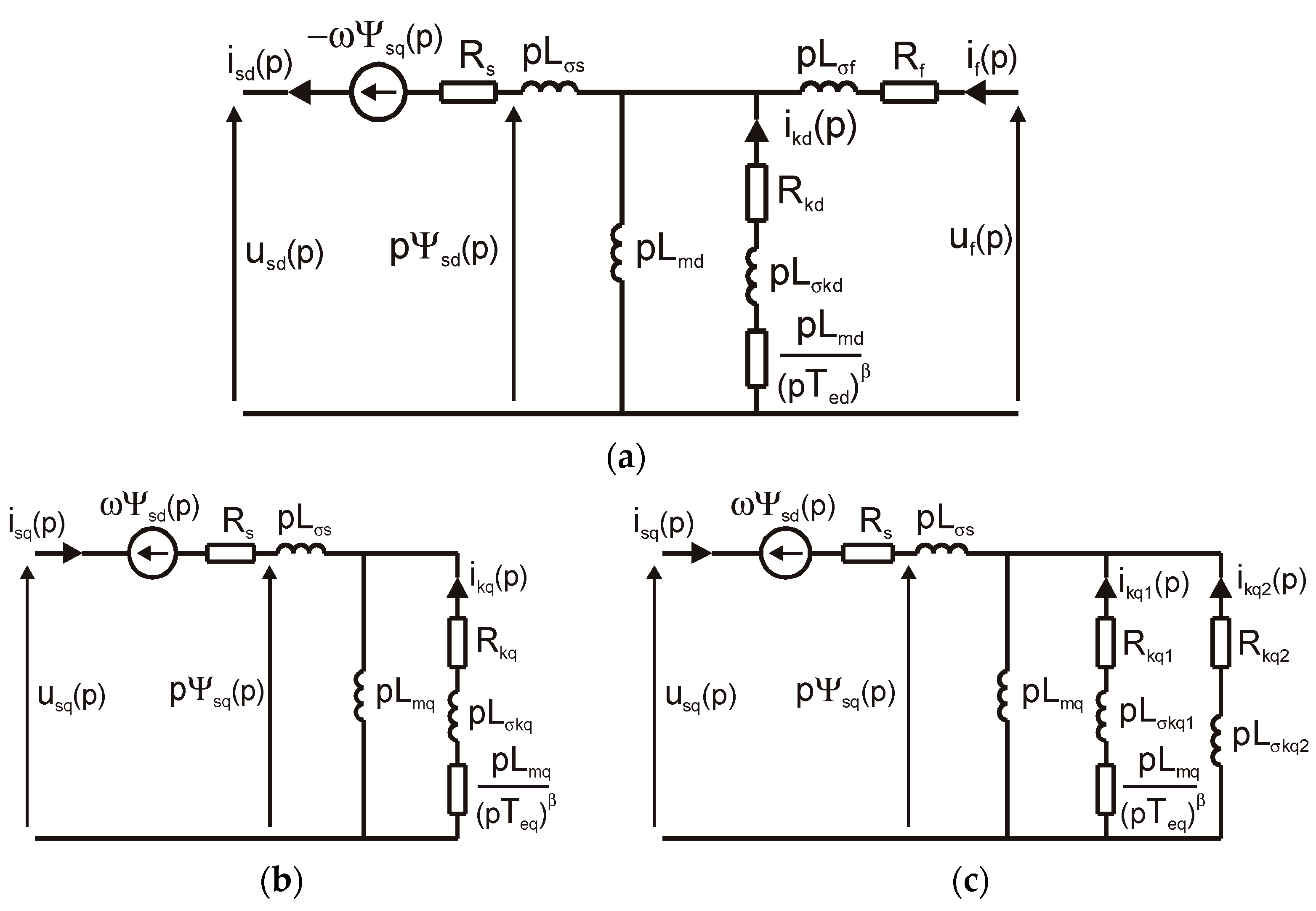
The analysis of transient states in synchronous machines is based on equivalent circuit models. To accurately represent the phenomena occurring within the solid rotor, the equivalent rotor electric circuit should be replaced with one or two lumped-parameter RL elements in the d-axis, and three or four RL elements in the q-axis, each characterized by different time constants (Figure 1).
An alternative approach is to represent the damper circuit of the solid rotor using a fractional-order impedance composed of hybrid elements [16], which are series combinations of lumped integer-order RL elements and a fractional-order element (Figure 2).
In the equivalent circuits, Rs and Rf are the resistances of the armature winding and field winding, Lσs and Lσf the leakage inductances of the armature winding and field winding, Lmd and Lmq the magnetizing inductances in the d- and q-axes, Ted and Teq the equivalent time constants of the rotor damper circuit (solid rotor, conducting wedges in the slots) in the d- and q-axes, and Rkd and Lσkd in the d-axis and Rkq and Lσkq in the q-axis are the resistance and leakage inductance with lumped parameters of the solid rotor damper circuit.
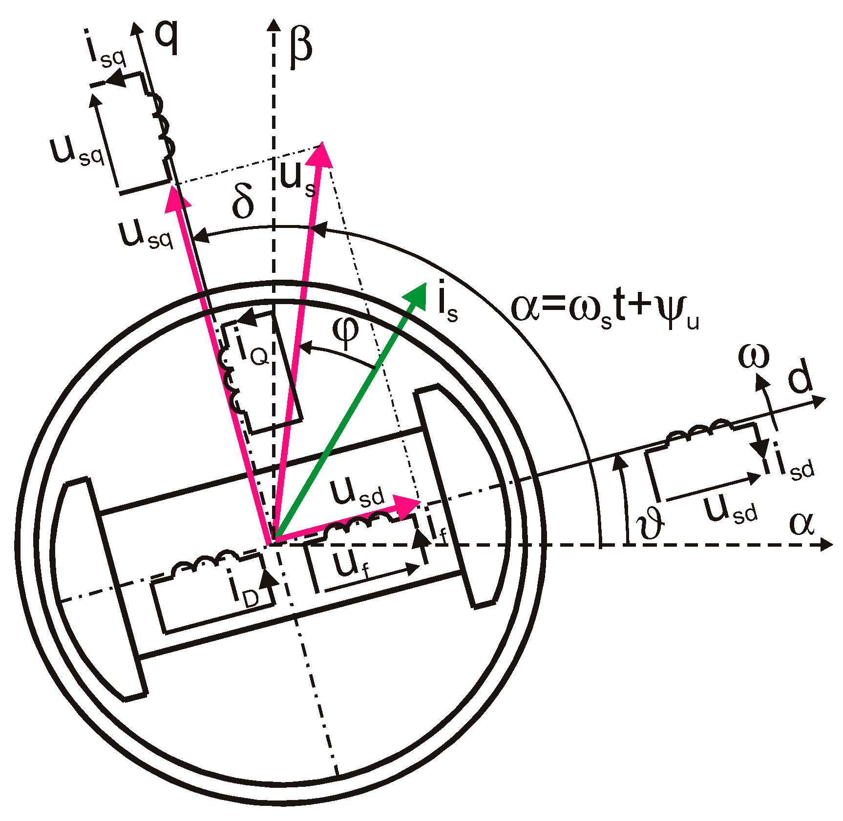
The analysis of electromechanical swings of a synchronous machine is conveniently carried out in Park’s d–q coordinate system [22,23] in the rotor reference frame (Figure 3). In this coordinate system, the rotational voltage components present in the equivalent circuits of Figure 1 and Figure 2 are eliminated.
The electrodynamic state of a synchronous machine, where the damper circuit of the solid rotor is modeled by a fractional-order impedance, in Park’s d–q coordinate system, applying the source-oriented arrow system for the stator and the load-oriented arrow system for the rotor, is described by the following equations.
The differential voltage equations for the stator in the d- and q-axes are
u s d = R s i s d + d Ψ s d d t   ω Ψ s q   u s q = R s i s q + d Ψ s q d t + ω Ψ s d
where usd and usq are the components of the armature voltage in the d- and q-axes, isd and isq are the components of the armature current in the d- and q-axes, Ψsd and Ψsq are the components of the flux linkage of the armature winding in the d- and q-axes, and ω is the electrical angular speed.
The differential voltage equation for the excitation circuit is
u f = R f i f + d Ψ f d t
where uf, if, and Ψf are the instantaneous values of the field voltage, field current, and flux linkage of the field winding, referred to as the armature winding side.
The differential voltage equations for the damper circuits of the solid rotor in the d- and q-axes, including fractional-order derivatives, are
e m d = d Ψ m d d t = R k d i k d + L σ k d d i k d d t + L m T e d β D α ( i k d ) e m q = d Ψ m q d t = R k q i k q + L σ k q d i k q d t + L m T e q β D α ( i k q )    
where Ψmd and Ψmq are the components of the main flux linkage in the d- and q-axes, ikd and ikq are the components of the damper winding current in the d- and q-axes, α is the order of the fractional derivative, and β = 1 − α, where 0 < α < 1.
The fractional-order derivatives appearing in Equation (3) are defined as follows [17]:
D α i k d = d α i k d d t α D α i k q = d α i k q d t α
The equations for the flux linkages related to the stator windings in the d- and q-axes and the excitation winding are
Ψ s d   = L s d i s d + L m d i f + L m d i k d   Ψ s q = L s q i s q + L m q i k q Ψ m d = L m d ( i s d + i f + i k d ) Ψ m q =   L m q ( i s q + i k q ) Ψ f =   L m d i s d +   L m d i k d + L f i f
The equation of motion is
J p b d ω d t = M m M e D p b ω
These equations must be supplemented by the equation for the electromagnetic torque:
M e   =   3 2 p b ( Ψ s d i s q     Ψ s q i s d )
It is assumed that the turbogenerator operates on a symmetrical three-phase stiff grid. In this case, the voltages applied to the stator phase windings are
u s a = U s m cos ( ω s t + ψ u ) u s b = U s m cos ( ω s t +   ψ u 2 3 )   u s c = U s m cos ( ω s t + ψ u 4 3 )
where usa, usb, and usc are instantaneous values of phase voltages a, b, and c, respectively; ωs is the angular frequency of the power grid; Usm is the amplitude of the phase voltage; and ψu is the initial phase angle of the voltage.
Applying the Park transformation [22],
u s d = 2 3 u s a cos ( ϑ ) + u s b cos ( ϑ 2 3 π ) + u s c cos ( ϑ 4 3 π )   u s q = 2 3 u s a sin ( ϑ ) + u s b sin ( ϑ 2 3 π ) + u s c sin ( ϑ 4 3 π )
to the phase voltages from Equation (7), the voltage components in the stator winding d- and q-axes are obtained as follows:
u s d   =   U s m sin ( ω s t   +   ψ u     ϑ ) u s q   =   U s m cos ( ω s t   +   ψ u     ϑ )
where ϑ is the angle between the axis of phase a of the armature winding and the rotor d-axis (Figure 3).
From the vector diagram in Figure 3, it follows that
u s d   = U s m sin δ = U s m cos ( π 2 δ ) u s q =   U s m cos δ = U s m sin ( π 2 δ )
where δ is the load angle.
By comparing Equations (9) and (10), we obtain
ω s t + ψ u ϑ = π 2 δ
Thus,
ϑ = ω s t + ψ u + δ π 2
Differentiating Equation (11) with respect to time yields the following relationship for the electrical angular velocity of the turbogenerator rotor:
ω = d ϑ d t = ω s + d δ d t
The time derivative of angular velocity is
d ω d t = d 2 ϑ d t 2 = d 2 δ d t 2
The equation of motion in Equation (5) can, therefore, be expressed as
J p b d 2 δ d t 2 + D p b d δ d t + D p b ω s + M e = M m
where J and D are the moment of inertia and the viscous damping coefficient of the generator–turbine set, respectively; Me and Mm are the electromagnetic torque and the turbine driving torque, respectively; and pb is the number of pole pairs.

3. Identification of Equivalent Circuit Parameters

The equivalent circuit parameters in the d- and q-axes of the synchronous machine (Figure 2) were determined by approximating spectral inductances derived from the analysis of electromagnetic field distributions using the finite element method (FEM) [24], with the machine at a standstill. These inductances are determined from the relations in Equation (A21).
L s d j ω = Ψ s d j ω I s d j ω U f = 0 = L s d 0 ( j ω )   p L f d ( j ω ) L d f ( j ω ) R f + p L f 0 ( p )   G f d j ω =   Ψ s d j ω U f j ω I s d = 0 = L d f ( j ω ) R f + p L f 0 ( j ω )
L s q j ω = Ψ s d ( j ω ) I s q ( j ω )
From relation Equation (15), it follows that the spectral transfer functions Lsd and Gfd can be determined based on the inductances Ld0, Lf0, and Ldf, obtained with the armature winding supplied and the field winding open, as well as with the field winding supplied and the armature winding open (Appendix A). The calculations were carried out in the FEMM 4.2 [25] software, under sinusoidal current excitation of either the armature or field winding in the frequency range from 0 to 1000 Hz.
Based on the structure of the synchronous machine’s equivalent circuit diagrams (Figure 2), the operator inductances Lsd(p) in the d-axis and Lsq(p) in the q-axis, as well as the transfer function Gfd(p), can be represented as ratios of polynomials with real coefficients and fractional-order exponents.
L s d p = L s d p 2 b 1 d + p α + 1 b 2 d + p b 3 d + p α b 4 d + b 5 d p 2 a 1 d + p α + 1 a 2 d + p a 3 d + p α a 4 d + a 5 d   G f d p = L m d R f p b 1 k + p α b 2 k + b 3 k p 2 a 1 d + p α + 1 a 2 d + p a 3 d + p α a 4 d + a 5 d
L s q p = L s q p b 1 q + p α b 2 q + b 3 q p a 1 q + p α a 2 q + a 3 q
The numerator and denominator coefficients of the polynomials of the inductance Lsd(p) and the transfer function Gfd(p) are functions of the parameter vector λd of the sought parameters of the equivalent circuit in the d-axis. Similarly, the numerator and denominator coefficients of the polynomials of the armature inductance Lsq(p) in the q-axis are functions of the vector λq of the sought parameters of the equivalent circuit in the q-axis.
λ d = L σ s L k d σ R k d T e d T   λ q = L σ s L k q σ R k q T e q T
The parameters of the equivalent circuit λd in the d-axis of the turbogenerator, and, consequently, of the approximating functions in Equation (17), are selected so that the magnitude of these functions approximates, with minimal error, the magnitude of the functions defined in Equations (15) and (16), which were obtained from electromagnetic field analysis. Similarly, the parameters of the equivalent circuit in the q-axis are determined. The sought values of the parameter vectors λd and λq are obtained by minimizing the sum of squared deviations.
For the d-axis,
ε d λ d = i = 1 N L s d ( f i ) L s d ( f i , λ d ) 2 + G f d ( f i ) G f d ( f i , λ d ) 2
For the q-axis,
ε q λ q = i = 1 N L s q ( f i ) L s q ( f i , λ q ) 2
where N is the number of measurement points, f is the frequency; Lsd, Lsq, and Gfd are the spectral quantities obtained from FEMM 4.2; and L*sd, L*sq, and G*fd are the spectral quantities from the approximating functions, determined from Equations (17) and (18) by substituting p = jω, where ω = 2πf.
To solve the non-linear Equations (20) and (21), the Levenberg–Marquardt algorithm implemented in Matlab R2010a [26] was used.
Figure 4, Figure 5 and Figure 6 present the frequency characteristics of the spectral inductances in the d- and q-axes of the TWW-200-2 turbogenerator, calculated using the FEM method and obtained based on the approximation with fractional-order rational functions Equations (17) and (18). The magnitude on the frequency characteristics is expressed in p.u. (per unit, i.e., relative to the selected base values).
Figure 7 and Figure 8 show the frequency characteristics of the spectral inductances, calculated using the FEM method and obtained from the approximation for the lumped-parameter model (Figure 1). The approximating functions of the operational inductances in the d- and q-axes were assumed in the form of Equation (22)
L s d p = L s d i = 1 n d ( 1 + p T d i ) i = 1 n d ( 1 + p T d 0 i ) L s q p = L s q i = 1 n q ( 1 + p T q i ) i = 1 n q ( 1 + p T q 0 i )
where Lsd and Lsq are the self-inductances of the armature winding in the d- and q-axes, respectively; Tdi and Td0i are the time constants in the d-axis; Tqi and Tq0i are the time constants in the q-axis; and nd and nq are the order of the operational inductance in the d- and q-axes, respectively.
Two equivalent circuits (nd = 3) were adopted in the rotor d-axis and four equivalent circuits (nq = 4) in the rotor q-axis.
To compare the amplitude and phase frequency characteristics of the spectral inductances calculated by the FEM 4.2 software with those derived from fractional-order approximations (Equations (17) and (18)), the relative error was calculated using the following definition [27]:
ε y   =   100 1 n i = 1 n ( Y i Y i ) 2 1 n i = 1 n Y i
where Y is the actual value, and Y* is the value obtained from approximation.
The values of the equivalent circuit parameters for the fractional-order model and the time constants for the lumped-parameter model are presented in Table 1 and Table 2 (quantities marked as p.u. are expressed in per unit, i.e., relative to the selected base values). These tables also include the values of the relative errors for the magnitude (εm) and phase (εφ), as well as the coefficient of determination R2.
The resulting relative errors for both magnitude and phase indicate good accuracy in approximating the amplitude and phase characteristics of the spectral inductance in the d-axis. However, significant discrepancies were observed in the phase characteristics in the q-axis when the damper circuit was modeled using a single equivalent circuit (Figure 2b). To achieve a high-accuracy approximation of these characteristics, it is necessary to use two equivalent circuits in the q-axis (Figure 2c).

4. Analysis of Electromechanical Swings of a Turbogenerator Under Small Disturbances Around the Equilibrium Point

4.1. Linearization of Differential Equations

The analysis of electromechanical swings addresses small disturbances from the stable equilibrium of a synchronous generator connected to an infinite bus, caused by variations in the turbine driving torque from the steady-state condition. A variation in the driving torque ΔMm is accompanied by variations in the voltage components Δusd and Δusq, the current components Δisd and Δisq, and the flux linkages ΔΨsd and ΔΨsq in the d- and q-axes, as well as variations in the electromagnetic torque ΔMe, the angular speed Δω, and the load angle Δδ. To obtain a system of linear differential equations, the nonlinear differential Equations (1) and (5) were linearized [28]. The assumption is made that, during stable operation of the generator under small disturbances, such as those that occur during normal operation of the power system [8], the electromechanical quantities are equal to the sum of the pre-disturbance values (denoted by subscript 0) and small deviations from the equilibrium point (denoted by the delta symbol). The following system of equations is then obtained:
u s d   =   U s d 0 + Δ u s d       i s d   =   I s d 0 + Δ i s d u s q   =   U s q 0 + Δ u s q       i s q   =   I s q 0 + Δ i s q Ψ s d   =   Ψ s d 0 + Δ Ψ s d       M e   =   M e 0 + Δ M e Ψ s q   =   Ψ s q 0 + Δ Ψ s q       M m   =   M m 0 + Δ M m ω   =   ω s + Δ ω           δ   =   δ 0 + Δ δ
By substituting the relations in Equation (24) into Equations (1), (6), (12) and (14), and subtracting the equations for the steady states, while neglecting the armature resistance and higher-order terms, the equations in the operator form are obtained:
Δ u s d p =   p Δ Ψ s d ( p ) ω s Δ Ψ s q ( p ) Δ ω ( p ) Ψ s q 0   Δ u s q   =   p Δ Ψ s q ( p ) + ω s Δ Ψ s d ( p ) + Δ ω ( p ) Ψ s d 0
Δ ω p = p Δ δ ( p )
Δ M e p =   3 2 p b ω s ω s Ψ s d 0 Δ i s q p   ω s Ψ s q 0 Δ i s d p + I s q 0 ω s Δ Ψ s d ( p ) I s d 0 ω s Δ Ψ s q ( p )
J p b p 2 Δ δ p + D p b p Δ δ p + Δ M e p = Δ M m ( p )
Taking into account the expression for the electromagnetic moment ΔMe(p) (A31) in Equation (28), we obtain the relationship for the load angle Δδ(p):
Δ δ p =   Δ M m ( p ) J ω s 2 p b p ω s 2   +   D ω s p b p ω s   +   + p b ω s   Q e 0 + 3 2 U s m 2 cos 2 δ 0 X s q ( p ) + sin 2 δ 0 X s d ( p ) + p ω s P e 0 + 3 4 U s m 2 1 X s q ( p ) 1 X s d ( p ) sin 2 δ 0
Equation (29) allows for determining the variation in the load angle as the driving torque changes. Using polynomial calculus in Matlab, Equation (29) can be expressed in the following form:
Δ δ p =   Δ M m p W p =   Δ M m ( p ) N ( p ) M ( p )
Both the numerator N(p) and the denominator M(p) of the algebraic fraction W(p) in Formula (30) are polynomials of the fractional order. This poses challenges for decomposing the function into partial fractions and, consequently, for converting the operator form into the time domain. The order of the fractional derivative of α in the expressions for the operator inductance Equations (17) and (18) is a decimal fraction in the range 0 < α <1. The exponent of α can be represented as a proper irreducible fraction:
α   =   n m   α   +   1   =   n m + 1   =   m + n m
where n and m are integers, and n < m.
In such a case, the exponents of the Laplace operator p of the inductances Lsd(p) and Lsq(p) in Equations (17) and (18) will be
p 2 = p 1 m 2 m p α + 1 = p 1 m m + n p 1 = p 1 m m p α = p 1 m n
Using the substitution
q = p 1 m
the operator inductances Lsd(p) and Lsq(p) in Equations (17) and (18) are transformed into
L s d p = L s d q 2 m b 1 d + q m + n b 2 d + q m b 3 d + q n b 4 d + b 5 d q 2 m a 1 d + q m + n a 2 d + q m a 3 d + q n a 4 d + a 5 d   L s q p = L s q q m b 1 q + q n b 2 q + b 3 q q m a 1 q + q n a 2 q + a 3 q
The order of the fractional derivative should be selected so that the polynomial degree of both the numerator and denominator of Lsd(q) is as low as possible. When α = 1/2, the resulting polynomial order is 4. When α = 2/5 or 3/5, the polynomial order is 10. Therefore, from the perspective of numerical computation, the most favorable order of the fractional derivative is α = 0.5. Furthermore, for fractional-order derivatives with α = 0.5, analytical expressions can be derived for the damping factor and the swing frequency.

4.2. Calculation of Transients

To simplify the calculations, it is convenient to use a relative units system. The following reference units are adopted:
I b   =   I s m N     U b   =   U s m N     S b   =   3 2 U s m N I s m N     M b   =   p b ω s S b     ω b   =   ω s Z b   =   U s m N I s m N       L b   =   Z b ω s           Ψ b   =   U b ω s t b   =   1 ω s
where UsmN and IsmN are the rated maximum phase values of the armature voltage and current, ωs is the synchronous speed, and pb is the number of pole pairs.
Introducing the relevant notations,
τ m = J ω s 2 p b M b   τ D = D ω s p b M b   p e 0 = P e 0 S b   q e 0 = Q e 0 S b b = u s m 2 sin 2 δ 0   c = u s m 2 cos 2 δ 0   d = u s m 2 2 sin 2 δ 0
and using a relative units system, Equation (29) can be rewritten in the following form:
Δ δ p =   Δ m m ( p ) p ω s 2 τ m + p ω s τ D + q e 0 + c x s q ( p ) + b x s d ( p ) p ω s p e 0 + d x s q ( p ) d x s d ( p )
where τm and τD are the starting time constant and the mechanical time constant of the turbogenerator set, respectively; xsd(p) and xsq(p) are the d- and q-axis operator reactance in relative units; and Δmm is the mechanical torque in relative units.
Considering relationships Equations (32)–(34), Equation (36) can be represented as a rational algebraic function of the variable q, with the numerator and denominator being polynomials with real coefficients of the integer order:
Δ δ p =   Δ m m ( p ) d 1 q r 4 + d 2 q r 5 + + d r 4 q + d r 3 c 1 q r + c 2 q r 1 + + c r q + c r + 1 = Δ m m ( p ) N ( q ) M ( q )
For an equivalent circuit comprising two rotor circuits in the d-axis and one rotor circuit in the q-axis, the polynomial degree is given by r = 3m + 4, where m is the denominator of coefficient α in the relationship in Equation (31). Thus, for α = 1/2, r = 10, and for α = 2/5, r = 19. For two rotor equivalent circuits in the d- and q-axes, the order of the polynomial is r = 4m + 4, and for α = 1/2, r = 12, and for α = 2/5, r = 24.
The transition from operator form to time form requires determining the roots of the denominator polynomial in Equation (37). Since the coefficients of the denominator polynomial M(p) of function Equation (37) are real, it has r roots, which may be real or occur as complex conjugate pairs. Some roots may have positive real parts. For α = 0.5 and two equivalent rotor circuits in the d- and q-axes (order of polynomial r = 12), the roots are presented in Table 3.
Thus, there are three negative real roots, six complex conjugate roots with negative real parts, and two complex conjugate roots with positive real parts, where the imaginary component exceeds the real component.
By decomposing Equation (37) into partial fractions, the operator equation for the increment in the power angle Δδ(p) can be written as
Δ δ p = Δ m m p i = 1 r Q i p 1 m q i = Δ m m ( p ) i = 1 r Q i p λ + b i
where qi represents the roots of the denominator polynomial in expression (37), bi = −qi, Qi represents the coefficients from the partial fraction decomposition, and λ = 1/m, where for α = 1/2 m = 2, λ = 0.5.
For a step change in the mechanical torque, Δmm(t) = Δmm1(t), and Δmm(p) = Δmm/p, and the variation in the load angle is determined by
Δ δ p = Δ m m p i = 1 r Q i p λ + b i = Δ m m i = 1 r Q i p ( p λ + b i )
From the relationship in Equation (26), it follows that the increment in the rotor angular velocity Δω(p), with a step change in the mechanical torque, is given by
Δ ω p = p Δ δ p = Δ m m i = 1 r Q i p λ + b i
Applying the inverse Laplace transform (A33) yields the time form of the functions in Equations (39) and (40):
Δ δ t =   Δ m m i = 1 r Q i b i 1 E λ ( b i t λ )   Δ ω t =   Δ m m i = 1 r Q i t λ 1 E λ , λ ( b i t λ )
where Eα,β (z) is the two-parameter Mittag-Leffler function in Equation (A34).
Further analysis of the electromechanical swings of the synchronous generator is carried out for fractional-order derivatives, where α = 0.5. In this case, the order of the denominator polynomial in Equation (37) is minimal, which improves the numerical stability of the partial fraction decomposition.
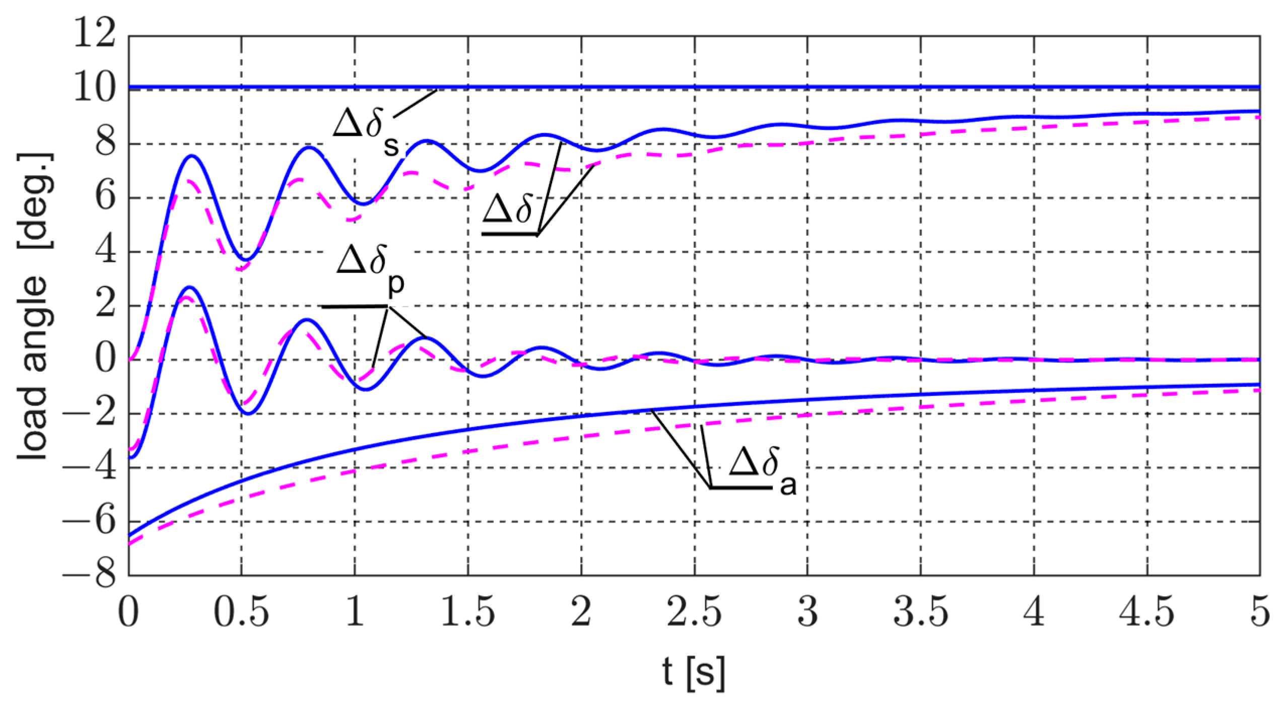
From the relationships in Equations (A35) and (A36), the load angle Δδ can be expressed as the sum of three components: the steady-state component Δδs, the aperiodic component Δδa, and the periodic component Δδp.
Δ δ t = Δ δ s ( t ) + Δ δ a ( t ) + Δ δ p ( t )
The corresponding equations describe each component:
Δ δ s t =   Δ m m i = 1 r 2 Q i b i i = r 1 r Q i b i Δ δ a t =   Δ m m i = 1 r Q i b i e b i 2 e r f c ( b i t ) Δ δ p t =   2 Δ m m i = r 1 r Q i b i e b i 2 t
When the fractional-order derivative in Equation (40) is of the order λ = 0.5, the angular velocity response Δω is given by
Δ ω t = Δ m m 1 π t i = 1 r Q i Δ m m i = 1 r Q i b i e b i 2 e r f c ( b i t ) + 2 Δ m m i = 1 r Q i b i e b i 2
From the partial fraction decomposition [2], if the degree of the numerator polynomial N(q) in Equation (37) is at least two orders lower than that of the denominator M(q), the sum ΣQi in Equation (44) equals zero. Thus, Equation (44) becomes
Δ ω t = Δ m m i = 1 r Q i b i e b i 2 e r f c ( b i t ) + 2 Δ m m i = r 1 r Q i b i e b i 2
The first term of Equation (45) represents the sum of the aperiodic components of the angular velocity:
Δ ω a   =   Δ m m i = 1 r Q i b i e b i 2 e r f c ( b i t )
Meanwhile, the second term of Equation (45) represents the periodic component of the angular velocity:
Δ ω p t =   2 Δ m m i = r 1 r Q i b i e b i 2 t
If br = x + jy, then exp(br2t) in Formulas (43) and (47) can be written as
e b r 2 t = e ( x 2 y 2 ) t e j 2 x y = e α h t ( cos ω h t + j sin ω h t )
where αh is the damping factor of the electromechanical swings, and ωh is the angular frequency of the electromechanical swings, defined as
α h = x 2 y 2 ω h = 2 x y
Given the relationship in Equation (48) and considering that br−1 = br* and Qr−1 = Qr*, the periodic components of the load angle Δδp and angular velocity Δωp can be expressed as
Δ δ p t = 4 Δ m m Re Q r b r e α h t ( cos ω h t + j sin ω h t )   Δ ω p t = 4 Δ m m Re Q r b r e α h t ( cos ω h t + j sin ω h t )
From Equations (43) and (45), it follows that during a transient following a step change in the driving torque, the steady-state component of the power angle Δδs and the aperiodic components of the power angle Δδa and angular velocity Δωa are determined by all the roots of the denominator polynomial in Expression (37). In contrast, the periodic components of the power angle Δδp and angular velocity Δωp are defined by two complex conjugate roots with positive real parts. From the relationship in Equation (49), the electromechanical swing frequency is equal to twice the product of the real and imaginary parts of the complex root with a positive real part, and the damping coefficient equals the difference in the squares of its real and imaginary parts. The periodic components of the responses of the power angle and the angular velocity will decay if the damping coefficient in Equation (49) is negative, which occurs when the real part of the root with a positive real part is smaller than its imaginary part.
The calculations of the power angle waveform were also performed for the lumped-parameter circuit model using the data presented in Table 2. Taking into account the relation in Equation (22), the operational expression of the power angle in Equation (36) for the lumped-parameter model, under a step change in the turbine torque, takes the following form:
Δ δ p   = Δ m m p d 1 p r 2 + c 2 p r 3 + + c r 2 p + c r 1 c 1 p r + c 2 p r 1 + + c r p + c r + 1   =   Δ m m i = 1 r Q i p ( p q i )
where r is the order of the denominator polynomial, and r = nd + nq + 2.
The roots of the polynomial of Equation (51) are presented in Table 3. The time-domain form of Equation (51) is defined by the relation
Δ δ t = Δ m i = 1 r Q i q i + Δ m i = 1 r 2 Q i q i e q i t + Δ m i = r 1 r Q _ i q _ i e q _ i t
The first term of Equation (52) represents the steady-state component. The second term represents the sum of the aperiodic components associated with the real roots. The third term of Equation (52) defines the periodic component of the power angle and is associated with a pair of complex conjugate roots qr = q*r–1. The real part of these roots determines the damping factor, while the imaginary part determines the frequency of the electromechanical oscillations. The values of the damping factor and the oscillation frequency are presented in Table 4.
The waveforms of the load angle and angular velocity, as well as the damping coefficient and electromechanical swing frequency, were calculated for the TWW_200 turbogenerator with the following rated parameters: PN = 200 MW, UN = 15.75 kV, IN = 8625 A, and cosφN = 0.85.
It was assumed that the time constant of the turbine generator unit Tm = 6.8 s, the induced voltage in the armature winding efm = 2.46 p.u., the load angle δ0 = 340, and the step change in the driving torque Δmm = 0.2.
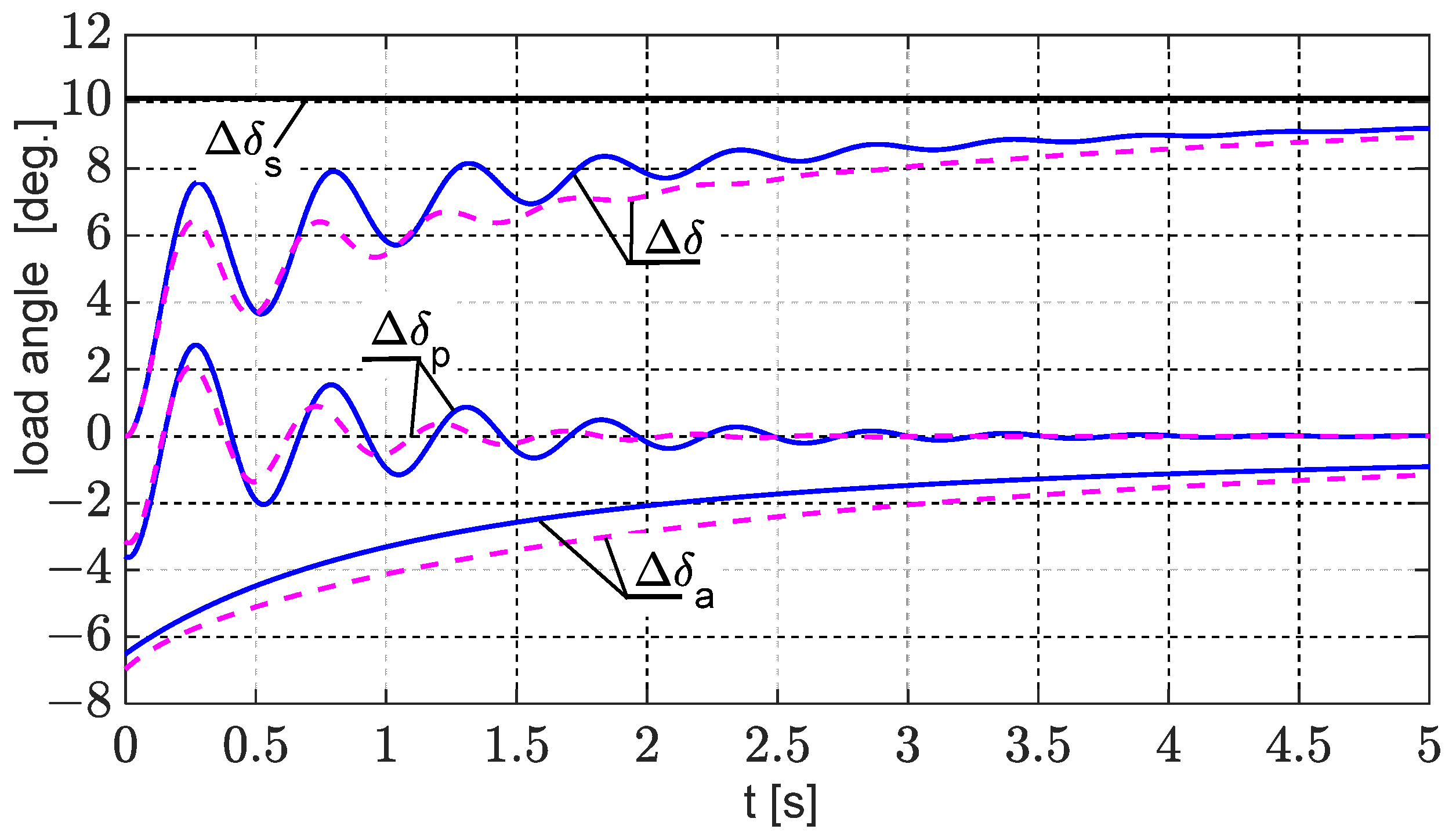
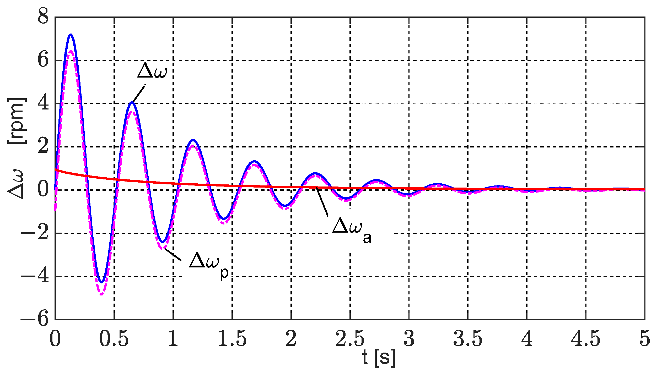
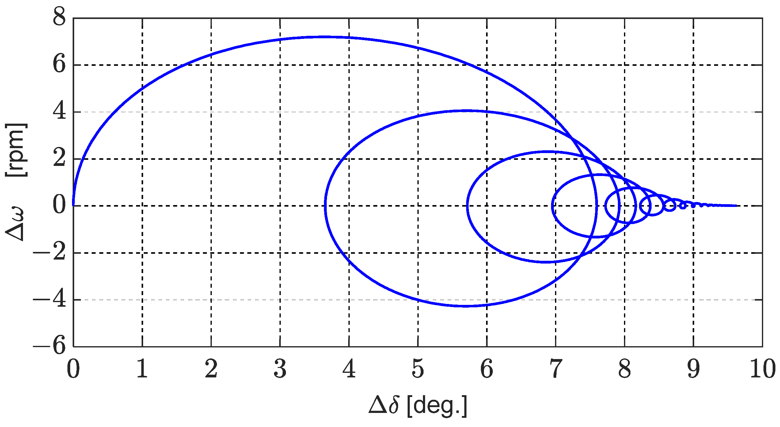
For the fractional-order model, Figure 9 and Figure 10 show the load angle and angular velocity waveforms, while Figure 11 presents the angular velocity–load angle trajectory.
From the waveforms presented in Figure 9, it follows that the number of equivalent circuits (Figure 2) used in the rotor affects the load angle waveform, as well as the values of the damping factor and the frequency of electromechanical swings (Table 4).
The values of the damping coefficient and the pulsation of electromechanical swings, calculated from Equation (49), are αh = 0.00351 pu and ωh = 0.03858 p.u, which correspond to the damping time constant and the electromechanical swing frequency of the turbogenerator: Th = 0.907 s and fh = 1.929 Hz.
Figure 12 compares the power angle waveforms calculated based on the fractional-order model and those determined from the lumped-parameter circuit model.
Table 4 presents the values of the damping factor αh and the pulsation ωh, as well as the time constant of damping Th and the frequency fh of the electromechanical swings (quantities marked as p.u. are expressed in per unit, i.e., relative to the selected base values).
The values of the swing frequency fh determined from the fractional-order model and the lumped-parameter model are similar.

5. Conclusions

From the conducted considerations and performed calculations, it follows that it is possible to determine the variation in the load angle of a synchronous generator connected to an infinite bus under small disturbances from the equilibrium state by applying fractional derivatives of order 0.5. In this case, analytical relations are obtained, on the basis of which the damping coefficient and the frequency of electromechanical swings can be determined.
The presented fractional-order model of the synchronous generator can be used to analyze small disturbances, such as those that normally occur in a power system. These disturbances are sufficiently small to allow the linearization of the differential equations around the equilibrium point. Therefore, this model cannot be applied to simulations of large disturbances, such as faults in the transmission system. Due to its computational complexity, it is also not suitable for real-time simulation.
Commonly used models of synchronous generators for power system analysis are based on equivalent circuit models with lumped parameters. They typically include one damper circuit in the d-axis and one in the q-axis, or two damper circuits in the d-axis and the q-axis. A drawback of lumped-parameter models is the difficulty of measurement-based identification of more than two equivalent circuits in the rotor in the d-axis and q-axis.
A key advantage of the fractional-order model is its accuracy in the frequency domain. The results indicate that the fractional-order model achieves a more precise fit of the frequency characteristics compared with the classical model with the same number of equivalent circuits in the rotor. Specifically, using one equivalent circuit in the rotor d-axis and two circuits in the q-axis for the fractional-order model corresponds to the need for two equivalent circuits in the d-axis and four circuits in the q-axis in the lumped-parameter model to attain comparable approximation accuracy. The correctness of the obtained results can be verified by calculating the steady-state value of the load angle using Equation (29) based on the final value theorem in the Laplace domain, and by calculating it from Equation (43) in the time domain. In both cases, the same values were obtained.
Future work will involve developing a cylindrical rotor synchronous generator model and performing both simulation and experimental studies under large disturbances, employing nonlinear integer-order and fractional-order models. The test setup will consist of a synchronous generator with a power of approximately 10 kW driven by a separately excited DC motor and a high-power single-phase sinusoidal voltage generator for measuring frequency characteristics of spectral transmittances in the range of 0.001–200 Hz.

Funding

This research received no external funding.

Data Availability Statement

The original contributions presented in this study are included in this article. Further inquiries can be directed to the corresponding author.

Conflicts of Interest

The author declares no conflicts of interest.

Abbreviations

The following abbreviations were used in this manuscript:
FEMFinite Element Method
SSFRStandstill Frequency Response

Appendix A

The differential voltage Equations (1) and (2), as well as the flux linkage equations for the armature and excitation windings, expressed in operational form for a stationary rotor (ω = 0), are as follows:
U s d p =   R s I s d ( p ) + p Ψ s d ( p )   U s q p =   R s I s q ( p ) + p Ψ s q ( p )
U f p = R f I f ( p ) + p Ψ f ( p )
Ψ s d p = L s d 0 ( p ) I s d ( p ) + L d f ( p ) I f ( p )   Ψ s q p = L s q ( p ) I s q ( p )
Ψ f p = L f 0 ( p ) I f ( p ) L f d ( p ) I s d ( p )
where Lsdo and Lsq are the operational inductances of the armature winding in the d- and q-axes, Lf0 is the operational inductance of the field winding, and Lfd and Ldf are the mutual operational inductances between the armature winding and field windings in the d-axis.
L s d 0 p = Ψ s d ( p ) I s d ( p ) I f = 0     L s q ( p ) = Ψ s d ( p ) I s q ( p ) L d f p = Ψ s d ( p ) I f ( p ) I s d = 0     L f d ( p ) = Ψ f ( p ) I s d ( p ) I f = 0 L f 0 p = Ψ f ( p ) I f ( p ) I s d = 0
The inductances Lsd0 and Lf0 should be increased by the end-winding leakage inductance of the armature and field windings, respectively. These inductances are determined from empirical formulas [29].
The inductances Ld0(p) and Lfd(p) correspond to the condition with the field winding open, whereas Lf0(p) and Ldf(p) correspond to the condition with the armature winding open.
By calculating the field current from Equation (A2), incorporating the expression for the flux linkage of the field winding in Equation (A4), and substituting it into Equation (A3), the expression for the flux linkage of the armature winding in the d-axis is obtained as follows:
Ψ s d p =   L s d 0 p p L f d L d f p R f + p L f 0 p I s d p +   L d f p R f + p L f 0 p U f p =       =   L s d p I s d p +   G f d ( p ) U f ( p )
where Lsd is the operator inductance of the armature with the field winding short-circuited, and Gfd(p) is the transfer function of the field circuit, with
L s d p = Ψ s d p I s d p U f = 0 = L s d 0 ( p ) p L f d L d f ( p ) R f + p L f 0 ( p )   G f d p = Ψ s d p U f p I s d = 0 = L d f ( p ) R f + p L f 0 ( p )
From the relationship in Equation (A7), it follows that the transfer functions Lsd(p) and Gfd(p) can be determined from the inductances Ld0(p), Ldf(p), Lf0(p), and Lfd(p), which are obtained under open-circuit conditions of either the armature or field winding. These transfer functions, along with the operator inductance Lq(p), form the core parameters used in the analysis of transient states in synchronous machines. By substituting the Laplace operator p = j ω, where ω = 2πf, into relationships Equations (A5) and (A7), the spectral inductances are obtained. Calculations performed for frequencies in the range of 0–1000 Hz yield the frequency characteristics of these spectral inductances. The spectral inductances were determined based on FEM simulations of electromagnetic field distribution with the machine at standstill. These calculations were carried out using the FEMM 4.2 software, applying sinusoidal currents to the armature or field windings over the 0–1000 Hz frequency range.
The spectral armature inductance Lsd0 in the d-axis and the mutual inductance between the armature winding and the field winding are determined by supplying two phases of the armature winding, with the rotor direct axis aligned with the resultant stator flux Ψ (ϑ = 90°) (Figure A1a), and the excitation winding open.
Figure A1. Diagrams for identifying the spectral inductances of the synchronous machine at standstill: (a) rotor in direct alignment; (b) rotor in quadrature alignment.
Energies 18 05170 g0a1
The following conditions apply: ϑ = 90°, isa = 0, isc =—isb, usa = 0, and usbusc = −ubc. Applying the Park transformation to Equation (8) under these conditions gives
i s d = 2 3 i s b = 2 3 i s i s q = 0    
u s d = u b c 3 u s q = 0    
Using relation Equation (A5), and taking into account Equations (A1), (A8), and (A9), an expression is obtained for the spectral inductance Lsd0 with the field winding open-circuited:
L s d 0 j ω =   1 j ω Ψ s d j ω I s d j ω   =   1 j ω U s d j ω I s d j ω R s   =   1 j ω 1 2 U b c ( j ω ) I b ( j ω )     R s
By introducing the notation
Z s j ω = U b c ( j ω ) I b ( j ω )
of the spectral inductance in Equation (A10), it can be written in the following form:
L s d 0 j ω =   1 2 Z s ( j ω ) 2 R s j ω   =   1 2 L s ( j ω )
Taking into account Equation (A8), the mutual spectral inductance Ldf is determined from the following relationship:
L f d j ω =   Ψ f j ω I s d j ω I f = 0   =   Ψ f j ω I s d p   =   3 2 Ψ f ( j ω ) I s ( j ω )
In the linear case, the spectral inductance Ldf is equal to the inductance Lfd. The FEMM 4.2 software enables direct computation of the spectral inductance Ls, impedance Zs, and resistance Rs in Equation (A12), as well as the associated flux Ψf in Equation (A13) for a given stator current frequency.
The spectral inductance Lsq in the q-axis is determined by supplying two phases of the armature winding, with the rotor q-axis aligned with the resultant stator flux (ϑ = 00) (Figure A1b). The following conditions apply: ϑ = 0, isa = 0, isc = −isb, and usa = 0 usbusc = −ubc. Applying the Park transformation in Equation (8) under these conditions gives
i s d = 0 i s q = 2 3 i s b = 2 3 i s    
u s d = 0 u s q = u b c 3    
Following the same procedure as for the d-axis, the spectral inductance in the q-axis is determined by
L q j ω = 1 2 Z s ( j ω ) 2 R s j ω = 1 2 L s ( j ω )
where the spectral impedance Zs, incorporating Equations (A14) and (A15), is defined by
Z s j ω = U b c ( j ω ) I b ( j ω )
The self-spectral inductance Lf0 of the excitation winding under open-circuit armature conditions is determined from the relationship in Equation (A5):
L f 0 j ω =   Ψ f ( j ω ) I f ( j ω )
The excitation flux Ψf and excitation current if appearing in the above relationships are quantities referring to the armature side. In contrast, FEMM 4.2 uses the actual quantities Ψf* and if* in its magnetic field analysis. To refer the field circuit quantities to the armature side, the voltage transformation ratio ku and current transformation ratio ki are applied [28].
k u = N s k w s N f k w f   k i = m 2 N s k w s N f k w f = m 2 k u
where Ns and kws represent the number of series turns of one stator phase and the winding factor of the stator; Nf and kwf represent the number of series turns and winding factor of the field winding; and m is the number of stator winding phases.
The flux linkage Ψf* and the field current if*, referring to the armature winding side, are, respectively, equal to
Ψ f = k u Ψ f   i f = i f k i
where Ψf* and if* are real quantities, and Ψf and if are referred quantities.
Based on the computed spectral inductances Ld0, Lfd, Lf0, and Ldf, determined under open-circuit conditions of the field winding (Ld0 and Lfd) or the armature (Lf0 and Ldf), the armature inductance in the d-axis with short-circuited field winding Lsd and the transfer function Gfd are determined.
L s d j ω = L s d 0 ( j ω ) j ω L f d L d f ( j ω ) R f + j ω L f 0 ( j ω )   G j ω = L d f ( j ω ) R f + p L f 0 ( j ω )
All calculations were performed using FEM-based electromagnetic field simulations over the frequency range of 0 ÷ 1000 Hz.

Appendix B

Appendix B.1

For steady-state conditions, Equations (1) and (4) take the following forms:
U s d 0   =   ω s Ψ s q 0 U s q 0   =   + ω s Ψ s d 0
ω s Ψ s d 0 = ω s L s d I s d 0 + E f m = U s q 0 ω s Ψ s q 0 = ω s L s q I s q 0 = U s d 0
From the relationship in Equation (10), it follows that
U s d 0 + Δ u s d = U s m sin ( δ 0 + Δ δ ) = U s m sin δ 0 cos Δ δ + U s m cos δ 0 sin Δ δ U s q 0 + Δ u s q = U s m cos ( δ 0 + Δ δ ) = U s m cos δ 0 cos Δ δ U s m sin δ 0 sin Δ δ
Assuming small deviations in the power angle increment Δδ, cosΔδ ≈ 1 and sinΔδ ≈ Δδ, the relationships from Equation (A24) take the following form:
U s d 0 + Δ u s d   =   U s m sin δ 0 + U s m cos δ 0 Δ δ U s q 0 + Δ u s q   =   U s m cos δ 0 U s m sin δ 0 Δ δ
Thus,
U s d 0 = U s m sin δ 0 U s q 0 = U s m cos δ 0
Δ u s d = U s m cos δ 0 Δ δ = U s q 0 Δ δ Δ u s q = U s m sin δ 0 Δ δ = U s d 0 Δ δ  
The transformation voltages appearing in Equation (25) can be neglected, since the transients associated with electromechanical swings can reasonably be approximated as slowly varying processes [23]. Equation (25), written in operator form and incorporating relationships Equations (26) and (A26), becomes
U s q 0 Δ δ p = ω s Δ Ψ s q ( p ) p Δ δ ( p ) Ψ s q 0   U s d 0 Δ δ p = ω s Δ Ψ s d ( p ) + p Δ δ ( p ) Ψ s d 0
The deviations in the flux linkages in the d- and q-axes are given by Equations (A3) and (A6):
Δ Ψ s d p =   L s d ( p ) Δ i s d ( p ) + G f d ( p ) Δ u f ( p )   Δ Ψ s q p =   L s q ( p ) Δ i s q ( p )
Assuming that the field winding voltage is unregulated, uf = Uf0, and the voltage deviation Δuf in Equation (A29) is zero. Using Equation (A29), and applying the relationship in Equation (A28), the armature currents in the direct axis Δisd and quadrature axis Δisq can be determined.
Δ i s d p = Δ Ψ s d p L s d ( p ) = U s d 0 + p Ψ s d 0 ω s L s d ( p ) Δ δ ( p )   Δ i s q p = Δ Ψ s q p L s q p = U s q 0 + p Ψ s q 0 ω s L s q ( p ) Δ δ ( p )
Taking into account the relationships in Equations (A23), (A27), (A29), and (A30), the expression for the electromagnetic torque (Equation (27)) becomes
Δ M e p = p b ω s Q e 0 + 3 2 U s m 2 cos 2 δ 0 X s q ( p ) + sin 2 δ 0 X s d ( p ) + p ω s P e 0 + 3 4 U s m 2 1 X s q ( p ) 1 X s d ( p ) sin 2 δ 0   Δ δ ( p )
where Pe0 and Qe0 are quantities representing active and reactive power, respectively.
P e 0 = 3 2 E f m U s m X s d sin δ 0 + 3 4 U s m 2 1 X s q 1 X s d sin 2 δ 0   Q e = 3 2 E f m U s m X s d cos δ 0 3 2 U s m 2 sin 2 δ 0 X s q + cos 2 δ 0 X s d

Appendix B.2

The inverse Laplace transforms of the operator expressions appearing in Equations (39) and (40) take the following form [30]:
1 p p λ + b   =   1 b 1 E λ ( b t λ )   1 p λ + b   =   t λ 1 E λ , λ ( b t λ )
where Eα,β (z) is the two-parameter Mittag-Leffler function [30,31], where Eα = Eα,1 (z).
E α , β = k = 0 z k Γ ( α k + β )
For the specific case λ = 0.5, the inverse transforms in Equation (A33) take the following form [11,30,32]:
1 p p 0.5 + b   =   1 b 1 e b 2 t e r f c ( b t )   1 p 0.5 + b   =   1 π t b e b 2 t e r f c ( b t )
If a complex root of qi of the denominator of the polynomial M(q) in Formula (40) has a positive real part, the inverse Laplace transform is obtained from the following relationship:
L 1 1 p p 0.5 b   =   1 b 1 e b 2 t e r f c ( b t ) + 2 ( e b 2 t 1 )   L 1 1 p 0.5 b   =   1 π t b e b 2 t e r f c ( b t ) + 2 b e b 2 t
where erfc(z) is the complement of the Gaussian error function [32].
The product of the complex function exp(z2)·erfc(z) for a complex argument z is calculated from the following series [11,30,32]:
e z 2 e r f c z =   e z 2 2 π z + k = 1 2 k z 2 k + 1 1 3 2 k + 1   =   γ 1 + j γ 2
For large arguments |z|, for which |arg(z)| < π/2, the relationship [11,30,32] may be applied:
e z 2 e r f c z =   1 π 1 z + k = 1 ( 1 ) k 1 3 ( 2 k 1 ) 2 k z 2 k + 1

References

  1. Paszek, S. Selected Methods for Assessment and Improvement of Power System Angular Stability; Silesian University of Technology Publishing House: Gliwice, Poland, 2012. [Google Scholar]
  2. Bronshtein, I.N.; Semendyayev, K.A.; Musiol, G.; Muechling, H. Handbook of Mathematics; Springer: Berlin/Heidelberg, Germany, 2007. [Google Scholar]
  3. Lindfield, G.; Penny, J. Numerical Method. Using Matlab; Academic Press, Elsevier: Amsterdam, The Netherlands, 2019. [Google Scholar]
  4. Machowski, J.; Białek, J.W.; Bumby, J.R. Power System Dynamics: Stability and Control; John Wiley & Sons Ltd.: Chichester, UK, 2008. [Google Scholar]
  5. Kutt, F.; Sienkiewicz, Ł.; Racewicz, S.; Michna, M.; Ryndzionek, R. Development of an emulation platform for synchronous machine power generation system using a nonlinear functional level model. Arch. Electr. Eng. 2024, 73, 281–297. [Google Scholar] [CrossRef]
  6. Luo, S.; Jian, Y.; Gao, Q. Synchronous generator modeling and semi-physical simulation. In Proceedings of the 22nd International Conference on Electrical Machines and Systems (ICEMS), Harbin, China, 11–14 August 2019; pp. 1–6. [Google Scholar] [CrossRef]
  7. Kamwa, I.; Viarouge, P.; Le-Huy, H.; Dickinson, J. A Frequency-Domain Maximum Likelihood Estimation of Synchronous Machine High-Order Models Using SSFR Test Data. IEEE Trans. Energy Convers. 1992, 7, 525–536. [Google Scholar] [CrossRef]
  8. IEEE Std 1110™-2019; IEEE Guide for Synchronous Generator Modeling Practices and Parameter Verification with Applications in Power System Stability Analyses. The Institute of Electrical and Electronics Engineers, Inc.: New York, NY, USA, 2020. [CrossRef]
  9. Wang, Q.Y.; Wang, S. Steady State Accuracy of Second-Order Generator Dynamic Models in Generator Parameter Validation Testing. In Proceedings of the 2020 IEEE Electric Power and Energy Conference (EPEC), Edmonton, AB, Canada, 9–10 November 2020; pp. 1–6. [Google Scholar] [CrossRef]
  10. Jalloul, A.; Trigeassou, J.K.; Jelassi, K.; Melchior, P. Fractional Order of Rotor Skin Effect in Induction Machines. In Nonlinear Dynamic; Springer: Berlin/Heidelberg, Germany, 2013; pp. 801–813. [Google Scholar] [CrossRef]
  11. Nadolski, R.; Staszak, J. Analysis of the Field Current after Three-Phase Sudden Short-Circuit of Turbogenerator using Equivalent Circuit. In Electrical Engineering; Springer: Berlin/Heidelberg, Germany, 1995; Volume 78, pp. 399–406. [Google Scholar]
  12. Xia, P.; Liang, Z. A Parameter Identification Method for Fractional Order Inductance of Iron Core Reactor. In Proceedings of the 2016 1st International Conference on Information Technology, Information Systems and Electrical Engineering, Yogyakarta, Indonesia, 23–24 August 2016; pp. 31–36. [Google Scholar] [CrossRef]
  13. Nadolski, R.; Staszak, J.; Harbaoui, L. Consideration of Solid Rotor Damping Circuit in Natural Hunting of Turbogenerator. Arch. Electr. Eng. 1998, XLVII, 235–245. [Google Scholar]
  14. Jalloul, A.; Trigeassou, J.K.; Jelassi, K.; Melchior, P. Non Integer Identification of Rotor Skin Effect in Induction Machines. Int. J. Electr. Comput. Eng. 2013, 3, 344–358. Available online: https://ijece.iaescore.com/index.php/IJECE/article/view/5458/4993 (accessed on 15 August 2025). [CrossRef]
  15. Racewicz, S.; Kutt, F.; Michna, M.; Sienkiewicz, Ł. Comparative Study of Integer and Non-Integer Order Models of Synchronous Generator. Energies 2020, 13, 4416. [Google Scholar] [CrossRef]
  16. Staszak, J. Solid-Rotor Induction Motor Modeling Based on Circuit Model Utilizing Fractional-Order Derivatives. Energies 2022, 15, 6371. [Google Scholar] [CrossRef]
  17. Xue, D.; Chen, Y.Q.; Atherton, D.P. Linear Feedback Control. In Analysis and Design with Matlab; Society for Industrial Applied Mathematics: Philadelphia, PA, USA, 2007. [Google Scholar]
  18. Spałek, D. Synchronous Generator Model with Fractional Order Voltage Regulator PIbDa. Acta Energetica 2015, 2, 78–84. [Google Scholar] [CrossRef]
  19. Tzounas, G.; Dassios, I.; Murad, M.A.A.; Milano, F. Theory and Implementation of Fractional Order Controllers for Power System Applications. IEEE Trans. Power Syst. 2020, 35, 4622–4631. [Google Scholar] [CrossRef]
  20. Hammami, R.; Bazine, I.; Jelassi, K. Parametric Identification of Fractional Park’s Model: Modal Approach. In Proceedings of the 7th International Conference on Modelling, Identification and Control (ICMIC), Sousse, Tunisia, 18–20 December 2015. [Google Scholar] [CrossRef]
  21. Minnich, S.H.; Chari, M.V.K.; Berkery, J.F. Operational Inductances of Turbine-Generators by the Finite-Element Method. IEEE Trans. Power Appar. Syst. 1983, PAS-102, 20–27. [Google Scholar] [CrossRef]
  22. Krause, P.C.; Wasynczuk, O.; Sudhoff, S.D. Analysis of Electrical Machinery and Drives System, 2nd ed.; IEEE Press, John Willey & Sons: Piscataway, NJ, USA, 2002. [Google Scholar]
  23. Paszek, W. Transient of AC Electrical Machines; WNT: Warszawa, Poland, 1986. [Google Scholar]
  24. Bastos, J.P.A.; Sadowski, N. Electromagnetic Modeling by Finite Element Method; Marcel Dekker: New York, NY, USA, 2003. [Google Scholar]
  25. Meeker, D. Finite Element Method Magnetics. User Manual, Version 4.2, 2015. Available online: https://www.femm.info/Archives/doc/manual42.pdf (accessed on 15 August 2025).
  26. Optimization Toolbox. User’s Guide Matlab; The MathWorks, Inc.: Natick, MA, USA, 2010. [Google Scholar]
  27. Babau, R.; Boldea, I.; Miller, T.J.E.; Muntean, N. Complete Parameter Identification of Large Induction Machines from No-Load Acceleration-Deceleration Test. IEEE Trans. 2007, 54, 1962–1972. [Google Scholar] [CrossRef]
  28. Lipo, T.A. Analysis of Synchronous Machines; CRC Press, Taylor & Francis Group: Boca Raton, FA, USA; London, UK; New York, NY, USA, 2012. [Google Scholar]
  29. Pyrhonen, J.; Jokinen, T.; Hrabovcova, V.P. Design of Rotating Electrical Machines; John Wiley & Sons Ltd.: Chichester, UK, 2014. [Google Scholar]
  30. Das, S. Functional Fractional Calculus for System Identification and Control; Springer: Berlin/Heidelberg, Germany, 2008. [Google Scholar]
  31. Rogosin, S.; Giraldi, F.; Mainardi, F. On the Laplace Transforms of Derivatives of Special Functions with Respect to Parameters. Mathematics 2025, 13, 1980. [Google Scholar] [CrossRef]
  32. Abramowitz, M.; Stegun, I.A. Handbook of Mathematical Function with Formulas, Graphs, and Mathematical Tables; Dover: New York, NY, USA, 1992. [Google Scholar]
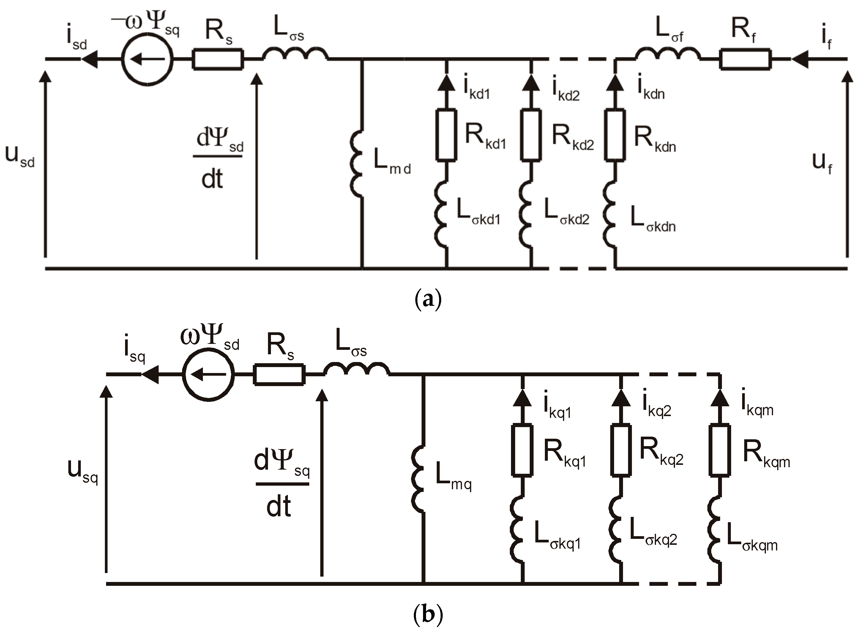
Figure 1. Equivalent circuit of a synchronous machine (a) in the d-axis and (b) in the q-axis, applying the source-oriented arrow system.
Energies 18 05170 g001
Figure 2. Equivalent circuit of a fractional-order synchronous machine: (a) in the d-axis, (b) in the quadrature q-axis with a single equivalent rotor circuit, and (c) in the q-axis with two equivalent rotor circuits, applying the source-oriented arrow system.
Energies 18 05170 g002
Figure 3. The d–q coordinate system of the synchronous machine in the rotor reference frame.
Energies 18 05170 g003
Figure 4. Frequency characteristics of the spectral inductance Lsd(jω) in the d-axis: (a) magnitude; (b) phase.
Energies 18 05170 g004
Figure 5. Frequency characteristics of the spectral inductance Lsq(jω) in the q-axis: (a) magnitude; (b) phase, with one damping circuit in the q-axis of the rotor (Figure 2b).
Energies 18 05170 g005
Figure 6. Frequency characteristics of the spectral inductance Lsq(jω) in the q-axis: (a) magnitude; (b) phase, with two damping circuits in the q-axis of the rotor (Figure 2c).
Energies 18 05170 g006
Figure 7. Frequency characteristics of the spectral inductances Lsd() on the d-axis for the lumped-parameter model: (a) amplitude; (b) phase.
Energies 18 05170 g007
Figure 8. Frequency characteristics of the spectral inductances Lsq(jω) on the q-axis for the lumped-parameter model: (a) amplitude; (b) phase.
Energies 18 05170 g008
Figure 9. Waveform of the load angle Δδ: Δδs—steady-state component, Δδa—aperiodic component, Δδp—periodic component, full line—two equivalent circuits, and dashed line—one equivalent circuit in the rotor q-axis.
Energies 18 05170 g009
Figure 10. Waveform of the rotor angular velocity Δω. Δωa—aperiodic component, and Δωp—periodic component.
Energies 18 05170 g010
Figure 11. Trajectory of angular velocity Δω versus load angle Δδ.
Energies 18 05170 g011
Figure 12. Waveform of the load angle Δδ: Δδs—steady-state component, Δδa—aperiodic component, Δδp—periodic component, full line—fractional-order model (two equivalent circuits in the rotor q-axis), and dashed line—lumped-parameter model.
Energies 18 05170 g012
Table 1. Equivalent circuit parameters for the fractional-order model.
Parameterd-Axis
Figure 2a
Parameterq-Axis
Figure 2bFigure 2c
Lsd [p.u.]1.812Lsq [p.u.]1.7751.775
Lσs [p.u.]0.186Lσs [p.u.]0.1860.186
Rkd [p.u.]0.001083Rkq [p.u.]0.001457
Lσkd [p.u.]0.000012Lσkq [p.u.]0.01029
Lσf [p.u.]0.1197Teq [s]5.9520.97
Rf [p.u.]0.00128Rkq1 [p.u.] 0.001593
Ted [s]11.708Lσkq1 [p.u.] 0.000011
α0.5Rkq2 [p.u.] 0.00735
εm [%]1.53Lσkq2 [p.u.] 0.4722
εφ [%]6.32α0.50.5
R2m0.9998εm [%]2.983.2
R2φ0.9958εφ [%]21.698.31
R2m0.99870.9985
R2φ0.89010.9839
Table 2. Time constants for the lumped-parameter generator model.
Parameterd-AxisParameterq-Axis
Figure 1aFigure 1b
Lsd [p.u.]1.812Lsq [p.u.]1.775
Lσs [p.u.]0.186Lσs [p.u.]0.186
Td1 [p.u.]386.560Tq1 [p.u.]1362.9
Td2 [p.u.]18.047Tq2 [p.u.]109.288
Td3 [p.u.]1.301Tq3 [p.u.]10.3458
Td01 [p.u.]2450.7Tq4 [p.u.]0.6357
Td02 [p.u.]22.872Tq01 [p.u.]1912.3
Td03 [p.u.]1.565Tq02 [p.u.]352.0454
εm [%]2.85Tq03 [p.u.]14.5075
εφ [%]6.51Tq04 [p.u.]0.9744
R2m0.9992εm [%]1.87
R2φ0.9955εφ [%]5.49
R2m0.9995
R2φ0.9930
Table 3. Roots of the denominator polynomial of the load angle transfer function.
iFractional-Order ModelLumped-Parameter Model
Figure 2cFigure 1
qiqi
1−1.1904∙100−1.5723∙100
2−5.3160∙10−1−7.6868∙10−1
3−1.2412∙10−1−9.3459∙10−2
4−6.5951∙10−4−5.3735∙10−2
5−9.9400∙10−2 + j1.2725∙10−1−6.4067∙10−3
6−9.9400∙10−2 − j1.2725∙10−1−1.4487∙10−3
7−1.9889∙10−2 + j4.550∙10−2−6.2823∙10−4
8−1.9889∙10−2 − j4.550∙10−2−4.6353∙10−3 + j4.0803∙10−2
9−8.2872∙10−3 + j9.3595∙10−2−4.6353∙10−3 − j4.0803∙10−2
10−8.2872∙10−3 − j9.3595∙10−2
111.3273∙10−1 + 1.4535∙10−1
121.3273∙10−1 + 1.4535∙10−1
Table 4. Values of the damping factor and the pulsation of electromechanical swings.
ParameterFractional-Order ModelLumped-Parameter Model (Figure 1)
One Circuit in the q-Axis (Figure 2b)Two Circuits in the q-Axis (Figure 2c)
αh [p.u.]−0.00565−0.0035094−0.0046353
ωh [p.u.]0.041680.0385850.040803
Th [s]0.5630.9070.687
fh [Hz]2.081.932.04
Disclaimer/Publisher’s Note: The statements, opinions and data contained in all publications are solely those of the individual author(s) and contributor(s) and not of MDPI and/or the editor(s). MDPI and/or the editor(s) disclaim responsibility for any injury to people or property resulting from any ideas, methods, instructions or products referred to in the content.