Article

Energy-Efficient Induction Heating-Based Deicing System for Railway Turnouts Under Real Snowfall Conditions

by
Hyeong-Seok Oh
1,
Woo-Young Ji
2,
Hyung-Woo Lee
3,
Jae-Bum Lee
4 and
Chan-Bae Park
1,*
1
Department of Railroad Operation Systems Engineering, Korea National University of Transportation, 157, Cheoldobangmulgwan-ro, Uiwang-si 16106, Republic of Korea
2
Department of Electrical Engineering, Hanyang University, 222, Wangsimni-ro, Seongdong-gu, Seoul 04763, Republic of Korea
3
Department of Railway Vehicle System Engineering, Korea National University of Transportation, 157, Cheoldobangmulgwan-ro, Uiwang-si 16106, Republic of Korea
4
Department of Railroad Electrical and Information Engineering, Korea National University of Transportation, 157, Cheoldobangmulgwan-ro, Uiwang-si 16106, Republic of Korea
*
Author to whom correspondence should be addressed.
Energies 2025, 18(19), 5149; https://doi.org/10.3390/en18195149 (registering DOI)
Submission received: 4 September 2025 / Revised: 20 September 2025 / Accepted: 26 September 2025 / Published: 27 September 2025
(This article belongs to the Special Issue Electric Machinery and Transformers III)

Abstract

Railway turnouts are highly susceptible to snow and ice accumulation during winter, which can cause malfunctions, resulting in train delays or, in extreme cases, derailments with potential casualties. To mitigate these risks, resistive heating (RH) systems using nichrome wires have traditionally been employed. However, these systems suffer from slow heat transfer and high power consumption. To address these limitations, this article proposes an induction heating (IH) system designed for rapid thermal response and improved electrical and thermal efficiency. The proposed system comprises a power conversion unit featuring a boost power factor correction (PFC) stage and a high-frequency resonant inverter, along with an improved IH coil. An experiment in real snowfall demonstrates the IH system’s fast heat-up capability, effective snow cover removal, and enhanced energy efficiency compared to conventional methods.

1. Introduction

Recent acceleration in global warming has led to increased variability in global climate patterns [1]. Some regions have experienced rising winter snow cover despite the overall increase in average temperature for the year. This paradox is largely attributed to the increased water vapor in the atmosphere, which results in heavier snowfall in areas where temperatures remain below freezing [2,3]. This trend also affects the railway industry. Figure 1 illustrates the structure of a railway turnout, one of the most important components of railway infrastructure. Unlike automobiles, railway vehicles do not possess steering mechanisms and thus rely on railway turnouts to determine their direction. The switching mechanism involves a reciprocating motion of the tongue rails, which are physically connected to the switch rod [4,5]. These tongue rails alternately contact the stock rails to direct the train. However, when snow accumulates between the tongue rail and the stock rail, it can be compacted into ice during the reciprocating movement [6,7,8]. This ice may interrupt contact, leading to switch malfunctions [9,10]. Such failures can result in train delays, operational disruptions, or, in extreme cases, derailments with potential threats to human safety. Therefore, maintaining the stable operation of railway turnouts during winter is directly linked to the reliability of railway systems [9,10,11,12,13].
Traditionally, resistive heating (RH) systems utilizing electric heating wires such as Nichrome have been widely adopted for deicing railway turnouts [12,13,14,15,16]. These systems operate by supplying electrical power to conductors installed along the stock rail, generating heat through Joule losses. The generated heat is then conducted into the stock rail, raising its temperature to melt snow cover and ice at the point panel. While the simplicity of this method is advantageous in terms of installation and maintenance, it suffers from significant thermal inefficiencies. Due to the large thermal mass and surface area of the rail, a substantial amount of time is required to reach effective deicing temperatures. Therefore, the RH system of 400 W/m requires continuous operation for a long period of time, so energy consumption is high [12,13,14]. This excessive electricity consumption leads to increased greenhouse gas emissions, thereby exacerbating the issue of global warming. Ironically, conventional deicing solutions designed to improve winter reliability may, in turn, accelerate climate degradation. Several studies have been conducted to solve these problems. Szychta proposed the induction heating (IH) slide plate which is based on inserting an additional slide plate between the stock rail and the tongue rail, with the aim of melting snow cover that accumulates in this critical gap [15]. The plate was compared with a conventional RH system under the same effective power condition of 450 W, and the results verified that IH achieved higher heating efficiency than RH. However, However, this approach does not replace the existing RH system but rather adds extra components to the turnout structure, which results in significant structural and economic burdens during installation. Żelazny investigated the performance of the IH device at different operating frequencies and demonstrated its energy-saving potential compared with RH system [7]. In conclusion, the IH device operating at about 70 kHz claimed to save about 70% of energy compared to RH. Nevertheless, this study did not consider the design of a power conversion system capable of reliably supplying power, and the experiments were also conducted with artificially generated ice in an environmental chamber instead of under real snowfall. Additionally, it does not consider the signal-frequency in railway.
By addressing the limitations of previous studies, the proposed IH system aims to provide a more practical and energy-efficient solution for railway turnout deicing. Therefore, this article proposes the IH-based deicing system that includes
  • Direct replacement of the conventional RH system;
  • Design consideration to avoid interference with Korean railway signal system;
  • Temperature regulation of the IH coil;
  • Experimental validation under an actual snowfall condition;
  • Performance comparison with conventional RH systems.
The proposed IH based deicing system consists of a power conversion stage and an IH coil, and it is designed to operate at approximately 62% of the power consumption of the conventional RH system used in the Republic of Korea. Several design considerations were incorporated to ensure compatibility with existing railway operations, including the physical dimensions of the RH system and the operating signal frequencies. In addition, temperature regulation of the IH coil was implemented to prevent damage due to overheating and to improve the overall efficiency of electrical energy usage. The deicing performance of the proposed system was experimentally verified under actual snowfall conditions, and its efficiency and power consumption were compared and analyzed against those of the conventional RH system. Ultimately, this article contributes not only to enhancing the operational reliability of railway networks during winter but also to mitigating environmental impacts by reducing energy consumption and greenhouse effect.

2. Conceptualization

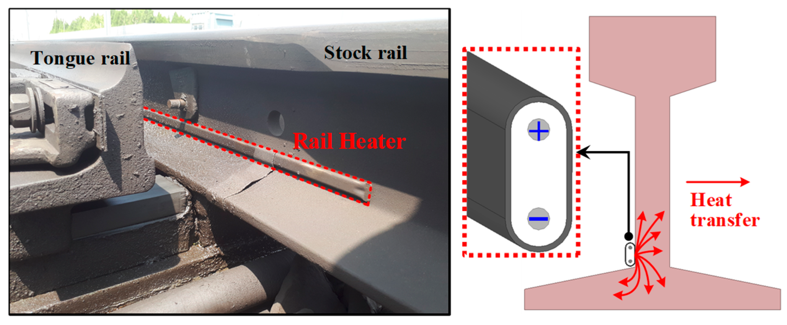
As described in the introduction, the conventional RH system operates by directly heating the bulky rail. Figure 2 presents a photograph of the Korean RH system, referred to as a rail heater, along with its heat transfer characteristics. This system applies to a commercial voltage of 220 Vrms and delivers 400 W/m to melt the snow cover on a stock rail. However, a railway turnout can be as long as 40 m, and in such cases, a huge amount of electrical energy is required [17]. To address this limitation, the proposed IH system introduces a new design concept, as shown in Figure 3. Figure 3 shows the overall configuration of the IH system for railway turnouts. The system is broadly divided into two parts: the power conversion stage and the heating stage. The power conversion stage consists of a boost power factor correction (PFC) circuit for power factor correction and a resonant inverter for maximum power transfer. In the heating stage, the IH coil is placed externally rather than making direct contact with the rail, so that the induced secondary-side heating effectively removes snow or ice accumulated between the stock rail and the tongue rail. In addition, a temperature controller is integrated into the power conversion stage to regulate the coil temperature and ensure stable operation.

3. Design Considerations

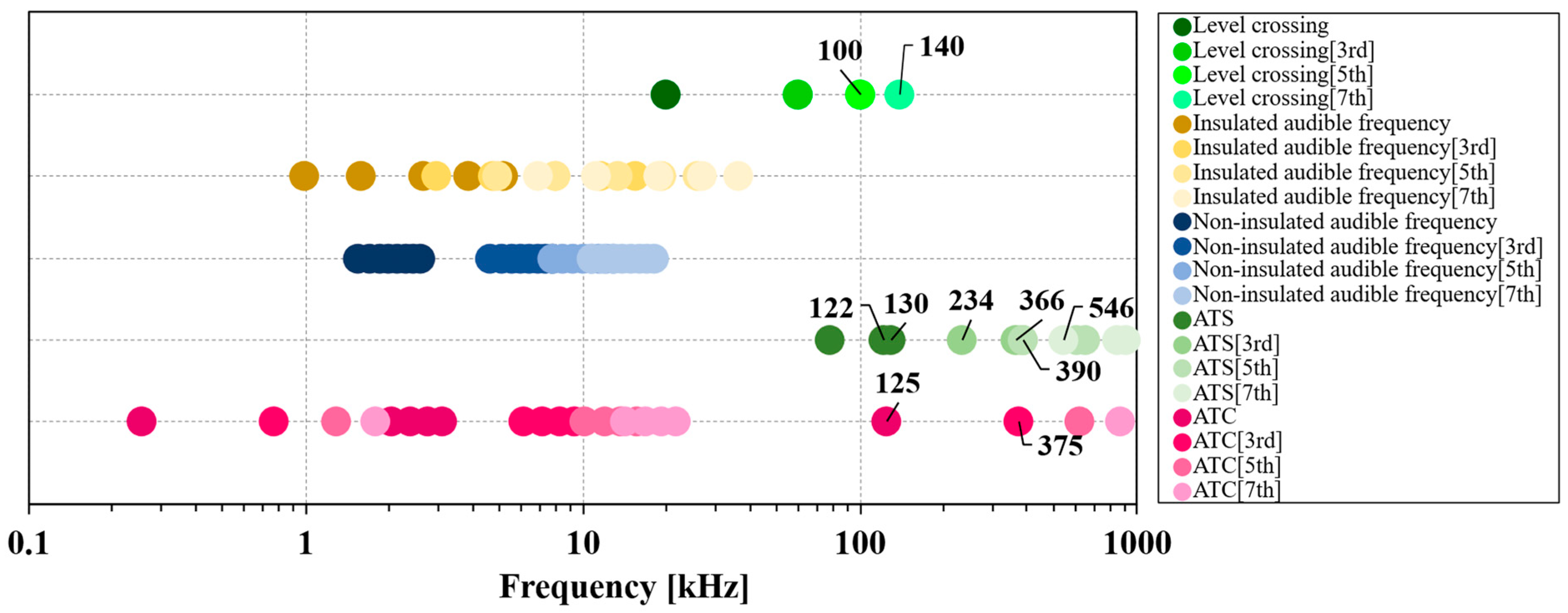
For the IH coil to replace the rail heater, the operating frequency f S must not interfere with existing railway signaling systems. Therefore, the frequencies used by railway signal systems were reviewed. Figure 4 shows the status of the major railway signaling frequencies in the Republic of Korea. In the figure, automatic train stop (ATS) and automatic train control (ATC) are indicated, while automatic train protection (ATP), which operates in the MHz range, is excluded from Figure 4. Therefore, f S should be selected within the appropriate range that avoids harmonics and potential interference with existing signal frequencies. In conclusion, the range of f S considering non-interference and temperature regulation is selected 250 to 350 kHz.
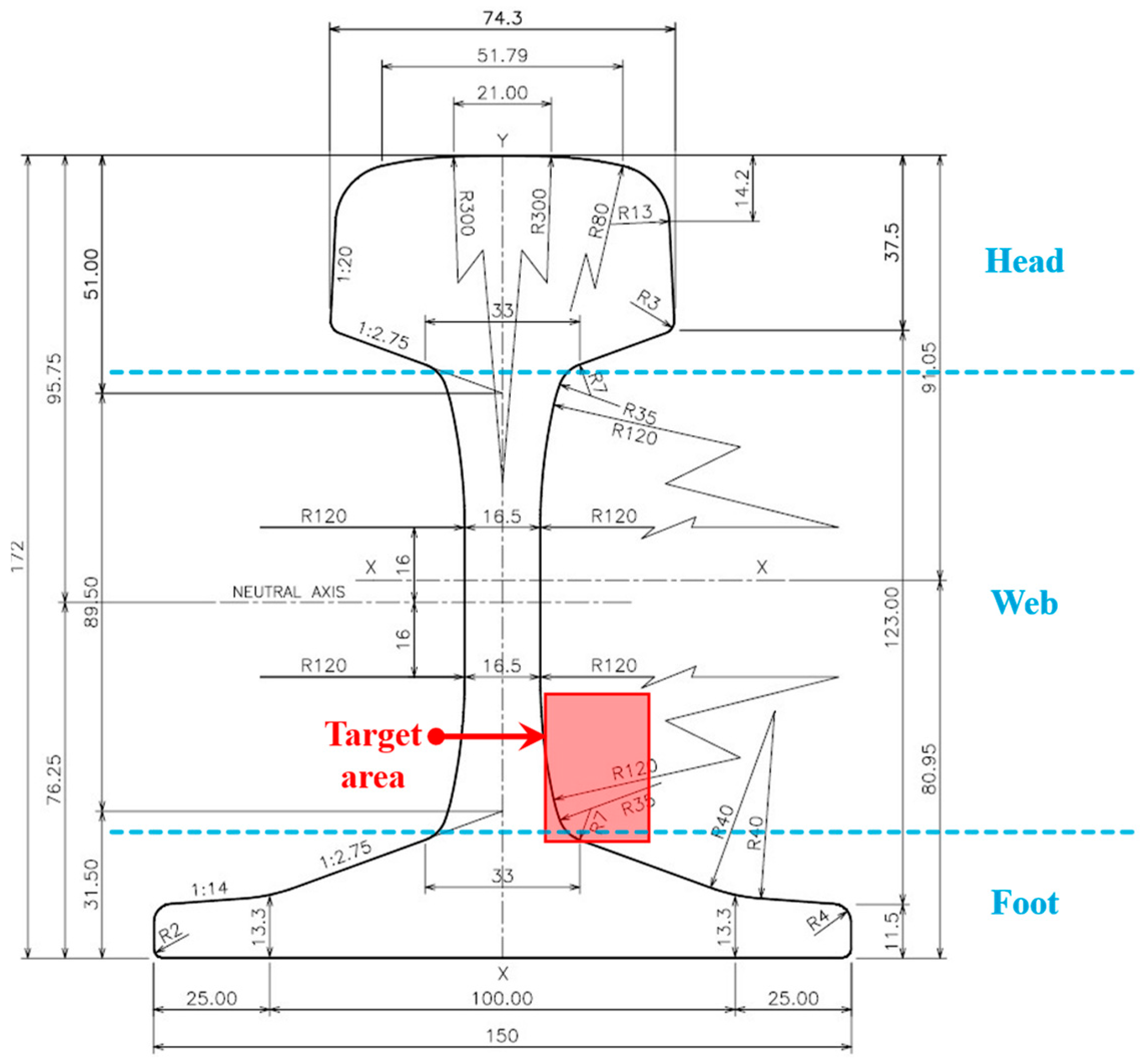
For the same reason described above, the target area of the IH coil was also examined. Figure 5 illustrates the dimensions of the UIC60 rail used in high-speed railway tracks. As shown in Figure 2, conventional rail heaters are installed near the boundary between the web and the foot, and the IH coil should likewise be targeted at this location. Consequently, the IH coil must satisfy the dimensional constraint of 25   ×   10 mm2 or smaller [10].

4. Design of the IH-Based Deicing System

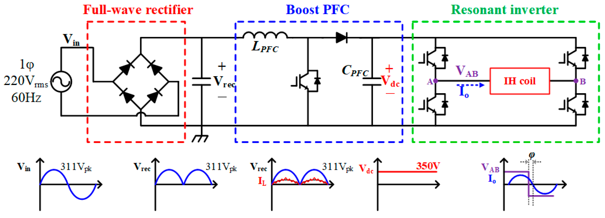
Figure 6 shows the circuit of the power conversion stage for the proposed IH system. It consists of a rectifier for AC/DC conversion, a boost PFC stage for power quality improvement and DC/DC conversion, and a resonant inverter that enables high-frequency operation and efficient power transfer. The nominal output power is set to 800 W, which can be adjusted depending on the length of the IH coil [12].
The details of the boost PFC stage are as follows: a full-wave rectifier of BU1006-M3 by Vishay is adopted to reduce component count and cost. In the boost PFC stage, the inductor and capacitor are designed based on key operating conditions. The inductance. L P F C of 945 μH is selected considering a switching frequency f P F C of 60 kHz and an input current ripple of 30% by Equation (1) [18]. When the line frequency f l i n e is 60 Hz, the f P F C is typically set to 60 kHz, resulting in approximately 1000 switching operations per line cycle [19,20,21]. In addition, this frequency does not interfere with railway signaling frequencies in Korea and lies outside the audible range. The inductor for boost PFC is fabricated to meet the previously calculated inductance, and its inductance is measured using IM3533 LCR meter by Hioki, confirming a value of 961 μH.
I i n   = V i n L P F C · D T S L P F C   = V i n · D I i n · f P F C
For the output capacitor, under the assumption of a unity power factor, the capacitance C P F C of 577 μF is calculated to calculated by Equation (2) to satisfy the voltage stress and a 3% ripple requirement, with the f l i n e taken as 60 Hz. The specifications and components of the PFC stage are summarized in Table 1 and Table 2.
C P F C = I o , m a x 2 · π · f l i n e · V d c · η P F C
The resonant inverter is configured in a full-bridge and applies a square-wave voltage V A B to the IH coil. Among the various sources of loss in the inverter, the dominant contributor is the switching loss due to the failure to achieve zero voltage switching (ZVS). To simplify the overall circuit design, the same switch used in the PFC stage is employed in the inverter. The maximum operating frequency of 350 kHz represents the worst-case condition in the inverter stage due to the combination of high switching frequency and low ZVS energy. Under this condition, the total loss in each switch is calculated to be 2.186 W, which consists of 0.046 W conduction loss, 0.263 W turn-on loss, 0.093 W turn-off loss, and 1.785 W capacitive loss. Figure 7 shows the 3D drawing of the power conversion stage. Meanwhile, the self-resonant frequency (SRF) generated by the parasitic capacitance of the PCB coil causes distortion in the load current. Therefore, an impedance matching network (IMN) was added to mitigate this issue. Figure 8 illustrates the equivalent circuit model with the added IMN, which has been discussed in detail in [14].
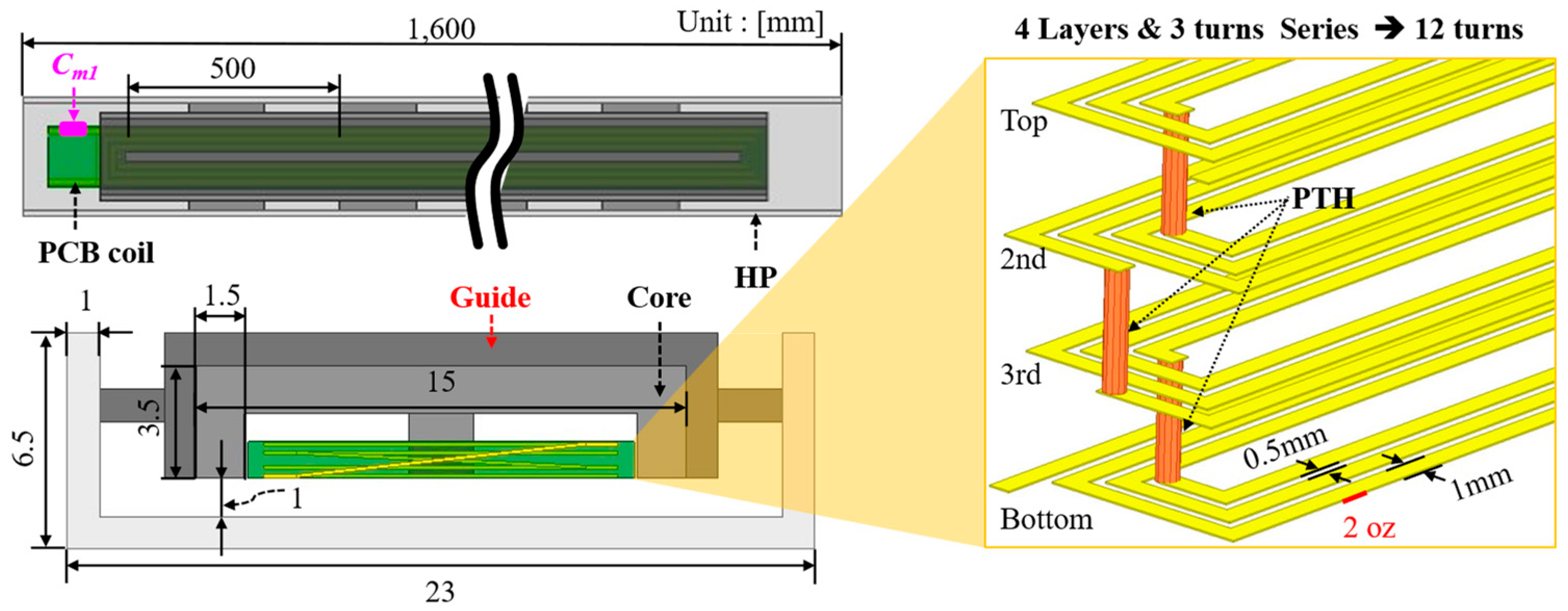
IH coil with PCB has been studied steadily [13,14,16]. and this article deals with the final improved IH coil. The previous IH coil was fabricated in a modular type, which made it difficult to effectively melt the snow cover between modules [13]. In addition, misalignment between the coil and the heating plate (HP) caused impedance unbalance among the modules. To address this issue, a guide is introduced to improve the impedance balance between modules in Figure 9. Furthermore, the HP was manufactured as a single object with a length of 1.6 m, thereby eliminating the problems inherent in the modular configuration. Figure 10 shows IH coils and final prototypes placed at 1.6 m HP.
In the PFC stage, I L must be in phase with the output voltage, requiring appropriate controller design. The control block diagram for the PFC stage is shown in Figure 11. A PI controller is operated to regulate the duty cycle. To obtain accurate sensing values, low-pass filters (LPFs) are employed: the cut-off frequencies are set to 12 kHz for output voltage sensing, 600 Hz for input voltage sensing, and 300 kHz for inductor current sensing.
Although the IH coil effectively melts snow or ice at high temperatures, excessive and continuous high power during the initial heating phase may cause thermal damage to the PCB-based IH coil. To achieve both rapid initial heating and long-term snow melting performance, a temperature regulation mechanism is required. A cost-effective and low-maintenance NTC thermistor of TT6-100KC3L was adopted to ensure reliable operation under sub-zero ambient conditions [22]. A PI controller was designed for temperature regulation, where the output is the switching frequency. The controller is illustrated on the right side of Figure 11. During the startup phase, the system operates at the minimum operating frequency 250 kHz to enable rapid heating. The target temperature is set to 50 °C, which is sufficient to ensure both safe operation of the IH coil and effective snow cover removal. Once the sensed temperature exceeds the reference, the switching frequency increases, thereby reducing the effective power delivered to the load.

5. Experiments and Tests

5.1. Room-Temperature Experiment

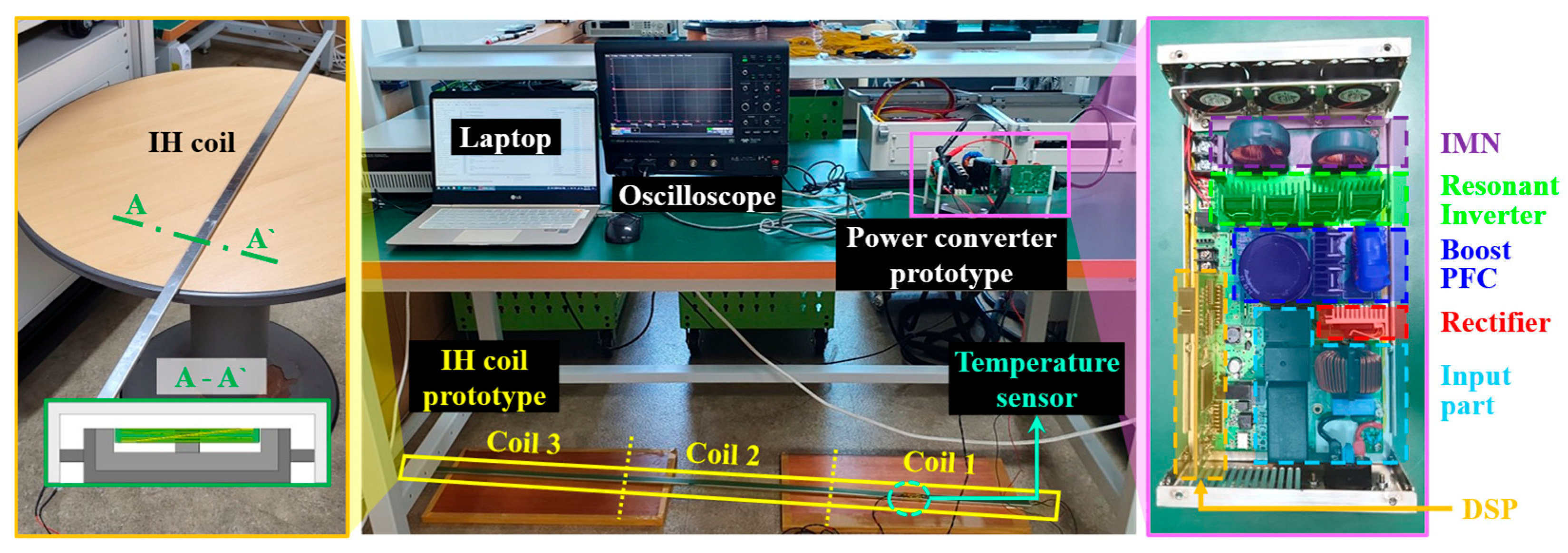
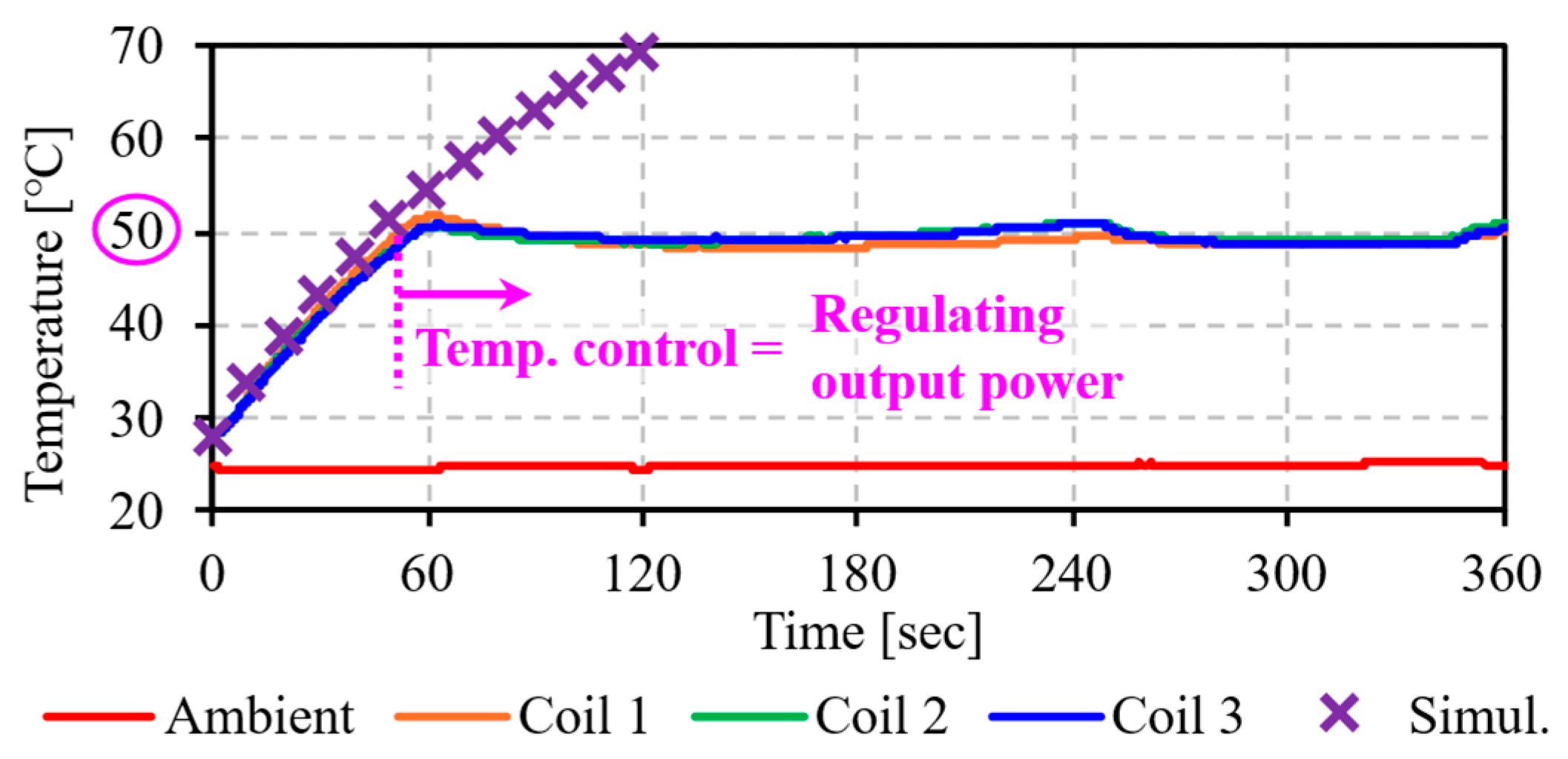
Figure 12 shows the test setup of the proposed IH system. The converter connected to a PCB-type IH coil, and the temperature is monitored using an NTC thermistor attached to the surface of IH coil. Figure 13 presents the experimental waveforms. The left plot shows the boost PFC operation under 100% load. It confirms that the peak of the inductor current stays below 6 A as designed, validating the 30% ripple criterion. The right plot illustrates the frequency operation of the resonant inverter for temperature regulation. The switching frequency initially starts at 250 kHz for rapid heating and is then increased up to 350 kHz to reduce power as the target temperature is approached. Figure 14 presents the temperature curves of the IH coil at different positions, measured under room-temperature conditions. The temperature was measured using a GP10 thermal recorder by Yokogawa, and T-type thermocouples were selected since they are suitable for measurements under humid and low-temperature conditions [23,24]. The simulation, which does not include temperature regulation, shows continuous heating. In contrast, the experimental result demonstrates that the proposed temperature feedback control successfully maintains the target temperature of 50 °C. At the same time, room-temperature experiments verified that the improved IH coil achieved uniform impedance across coils, resulting in minimal temperature variation.

5.2. Actual Snowfall Experiment

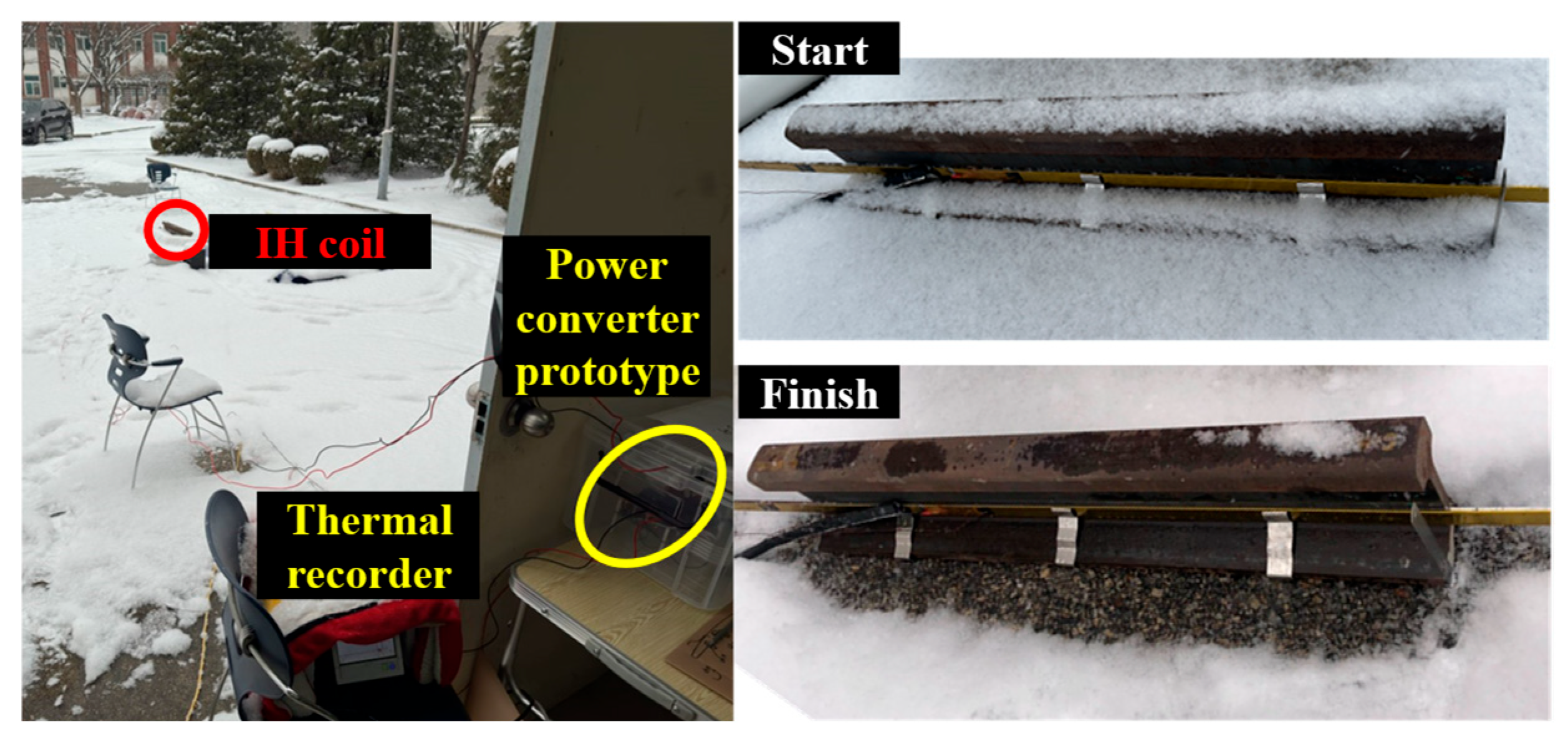
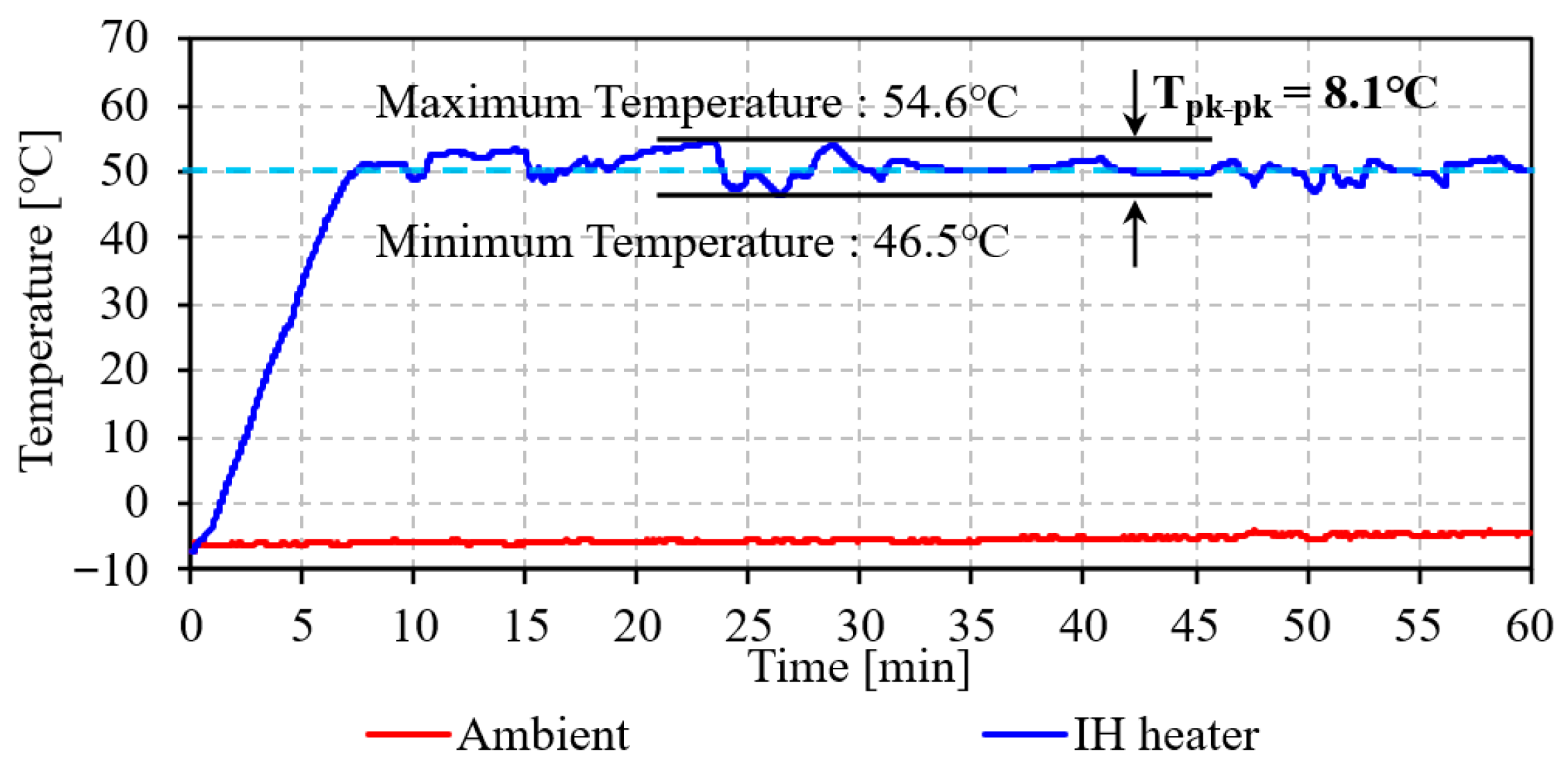
To verify the deicing performance under actual snowfall, the experimental setup was configured as shown in Figure 15. First, the snow cover over a six-hour period was monitored as shown in Figure 16. Six hours after the onset of snowfall, a snow cover height of 2.5 mm was observed on the rail head. This experiment was performed for one hour, and the results are illustrated in Figure 17. A maximum temperature deviation of 8.1 °C was recorded, demonstrating stable operation. From these results, the deicing performance of the proposed system was successfully validated.

5.3. Field Application Tests

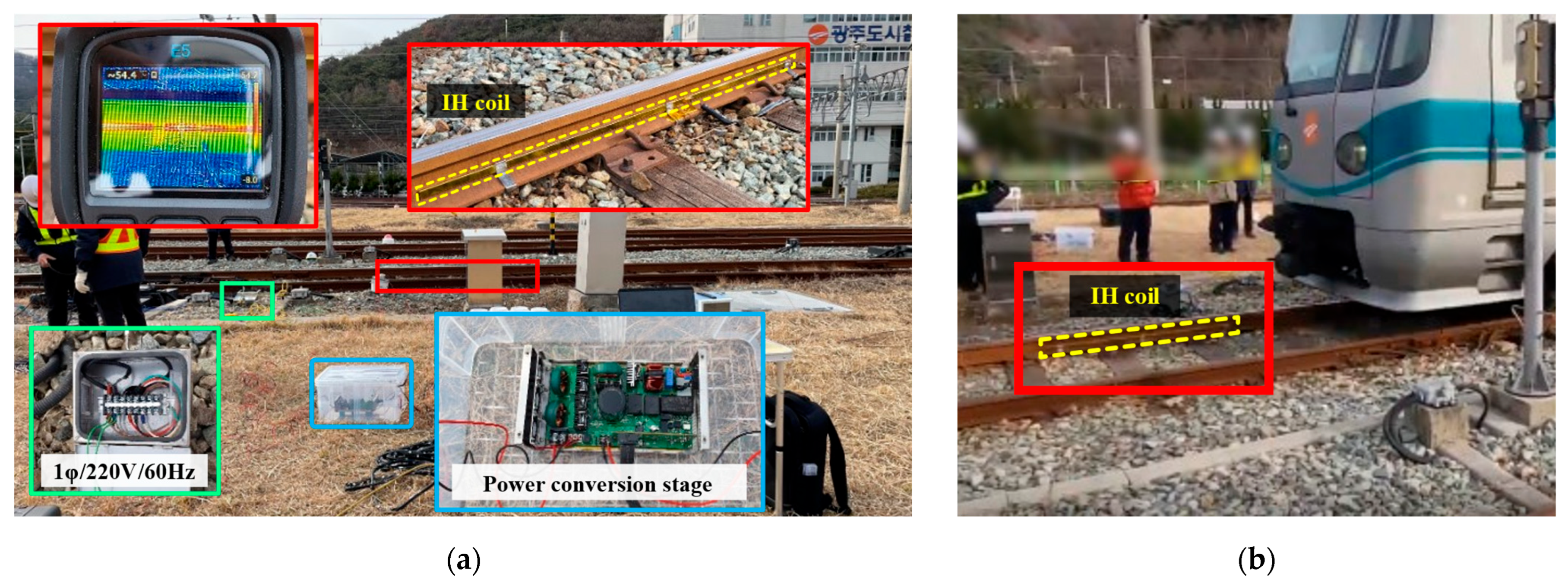
A performance test through field installation was conducted. The purpose of this test was to verify that no interference occurred during actual railway operation and that the IH coil was not damaged while the railway vehicle was running. Figure 18 presents photographs of the field test. In Figure 18a, an input power was supplied through a power supply box indicated in green, while the blue and red boxes highlight the power conversion stage and the IH coil, respectively. The red box at the upper left of (a) shows an image captured using a thermal imaging camera E5-XT by FLIR, from which it can be confirmed that the target temperature of about 50 °C was achieved [25]. Figure 18b depicts part of the setup during operation, where the IH coil can be seen in the red box, confirming that there was no issue with train driving. To further verify whether the coil was damaged by vibrations generated during train operation, the system underwent the accredited Degrees of Protection by Enclosures (IP Code) test in accordance with KS C IEC60529:2013 [26]. As a result, there were no signs of water penetration inside the IH coil, and it was rated IPx7. Figure 19 shows an excerpt from the corresponding test report, showing the 1 m depth according to the test method and the disassembled IH coil used to check for signs of water penetration after the test.

6. Discussion

The proposed deicing system employs IH technology and offers the advantage of rapid heating. To verify this benefit, the output due to heat generation was compared with the input of the conventional rail heater and the proposed system, using the specific heat Equation (3).
P o _ t e m p = c m T
where c denotes the specific heat [J/kg·℃], m the mass [kg], T the temperature change over time [°C/s], and P o _ t e m p the thermal output [W].
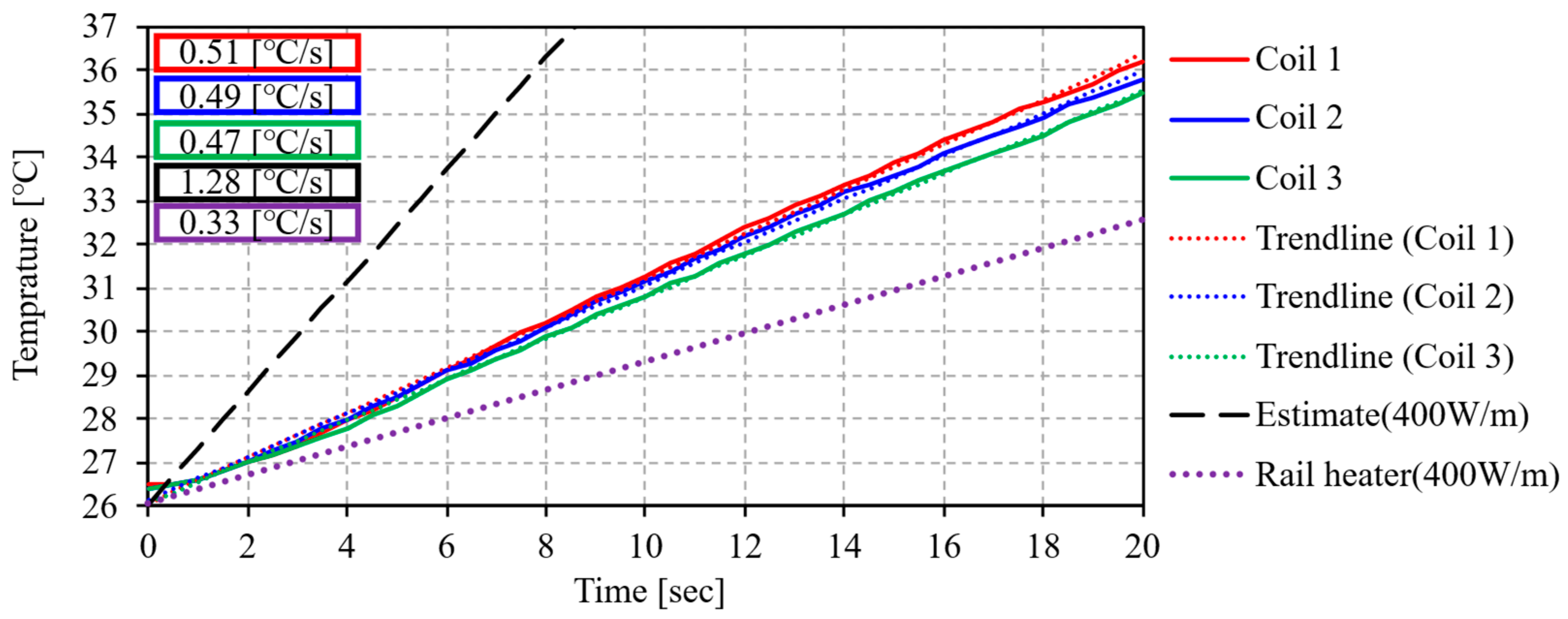
The values of parameters for each system are summarized in Table 3. The temperature change was obtained from the slope of the temperature curve at the IH coil measurement points. The temperature change over time of each coil was 0.51, 0.49, and 0.47, with 0.49 adopted for consistent comparison. The input power of the proposed system measured at the power conversion stage was 245.9 W, as shown in Figure 20. Normalized by the rail length, this corresponds to 153.6 W/m in comparison with the rail heater. Figure 21 presents the results, showing the temperature rise and slope of each system over time. For the rail heater, the thermal output and efficiency were calculated as 109.2 W/m and 27.3%, respectively. In contrast, the proposed system achieved 57.4 W/m and 37.4%. If the proposed system is assumed to operate at the same input power as the rail heater (400 W/m), the estimated output would be 149.5 W/m. Taking the RH system as the baseline (100%), the IH system demonstrates an efficiency improvement to 137% and a reduction in power consumption to 38%. In conclusion, based on the ratio of thermal output to input, the proposed system has been verified to deliver short-time heating capability, improved efficiency, and reduced power consumption compared with the conventional rail heater.

7. Conclusions

This article proposes an energy-efficient induction heating (IH)-based deicing system for railway turnouts. Conventional resistive heating (RH) has been widely used for turnout deicing due to its structural simplicity and ease of installation. However, it suffers from high power consumption and low thermal efficiency. To address these limitations, reliable IH technology was employed to develop a deicing system.
The proposed system consists of two main stages, a power conversion stage and a heating stage. In the heating stage, the IH coil was designed to be directly replaceable with existing rail heaters in the Republic of Korea. Two primary design considerations were considered. The first was maintaining dimensions like the rail heaters to ensure ease of installation. The second was avoiding interference with the existing railway signaling system. To meet these requirements, the frequency ranges of the signaling systems and the specifications of the UIC60 rail were reviewed to establish design constraints.
For high-frequency IH operation, a resonant inverter was designed in the power conversion stage, and a boost PFC stage was added for power factor correction. The boost PFC was implemented in a typical configuration and analyzed for loss characteristics. To simplify the design, the same switching devices were employed throughout the circuit. The IH coil was developed as a final prototype that addresses the limitations observed in previous modular designs. Earlier modular coils suffered from impedance imbalance between modules and insufficient deicing at the module junctions. To overcome this, the heating plate (HP) was integrated into a single structure. In addition, the operating frequency range was selected to avoid interference with railway signaling, and a temperature control system was designed to regulate coil temperature by frequency variation. This design not only prevents IH coil damage but also reduces electrical energy.
Room-temperature experiments verified the stable operation of the system. Actual snowfall tests confirmed the deicing performance under natural snow cover. Furthermore, a field installation test demonstrated that the system did not interfere with train operation. After the field test, the IH coil underwent accredited IP code certification, which confirmed that no damage occurred due to vibrations generated during train operation. Finally, compared with the conventional rail heater, the thermal output relative to input power was evaluated. The proposed system achieved a 37% improvement in heating efficiency and a 62% reduction in power consumption compared with the conventional RH system.

Author Contributions

Conceptualization, H.-S.O. and H.-W.L.; methodology, H.-S.O.; software, H.-S.O. and W.-Y.J.; validation, H.-S.O. and W.-Y.J.; formal analysis, H.-S.O.; investigation, H.-S.O.; resources, J.-B.L., H.-W.L. and C.-B.P.; data curation, H.-S.O. and W.-Y.J.; writing—original draft preparation, H.-S.O.; writing—review and editing, C.-B.P.; visualization, H.-S.O.; supervision, J.-B.L., H.-W.L. and C.-B.P.; project administration, H.-W.L.; funding acquisition, J.-B.L., H.-W.L. and C.-B.P. All authors have read and agreed to the published version of the manuscript.

Funding

This study was conducted with the support for the Ministry of Trade, Industry and Energy/Korea Evaluation Institute of Industrial Technology (Project No.: RS-2024-00443316/Development of a High Torque Density Magnetic Geared Drive System with Structural Robustness).

Data Availability Statement

The data presented in this study are available on request from the corresponding author. The data are not publicly available due to privacy and research project restrictions.

Conflicts of Interest

The authors declare no conflicts of interest.

References

  1. Kim, Y.-S.; Lee, S.-H. Trends of extreme cold events in the central regions of Korea and their influence on the heating energy demand. Weather Clim. Extrem. 2019, 24, 100199. [Google Scholar] [CrossRef]
  2. Huang, E.; Zhu, G.; Wang, Y.; Li, R.; Miao, Y.; Qi, X.; Wang, Q.; Jiao, Y.; Wang, Q.; Zhao, L. Long-Term Snow Cover Change in the Qilian Mountains (1986–2024): A High-Resolution Landsat-Based Analysis. Remote Sens. 2025, 17, 2497. [Google Scholar] [CrossRef]
  3. Quante, L.; Willner, S.N.; Middelanis, R.; Levermann, A. Regions of intensification of extreme snowfall under future warming. Sci. Rep. 2011, 11, 16621. [Google Scholar] [CrossRef] [PubMed]
  4. Kisilowski, J.; Kowalik, R. Mechanical Wear Contact between the Wheel and Rail on a Turnout with Variable Stiffness. Energies 2021, 14, 7520. [Google Scholar] [CrossRef]
  5. Loidolt, M.; Marschnig, S.; Bürgler, M.; Berghold, A.; Dornig, P.; Ossberger, U. Quality Behaviour of Turnouts: Comparison, Problem Specification and Recommendation of Measures. Appl. Sci. 2023, 13, 10665. [Google Scholar] [CrossRef]
  6. Loponen, T.R.; Salmenperä, P.; Luomala, H.; Nurmikolu, A. Studies of Snow-Dropping from a Train on a Turnout due to Dynamic Excitations. J. Cold Reg. Eng. 2018, 32, 04018003. [Google Scholar] [CrossRef]
  7. Żelazny, R.; Jabłoński, P.; Szczegielniak, T. Operation of the Prototype Device for Induction Heating of Railway Turnouts at Various Operating Frequencies. Energies 2021, 14, 476. [Google Scholar] [CrossRef]
  8. Flis, M. Contactless turnouts’ heating for energy consumption optimization. Arch. Electr. Eng. 2020, 69, 133–145. [Google Scholar] [CrossRef]
  9. Heger, J.; Kurzweil, F.; Schladitz, M.; Adam, R.; Großmann, S. Experimental Verification of an Optimized Heating System for Hollow Sleepers Containing Points Positioning Systems. In Proceedings of the 5th International Conference on Road and Rail Infrastructure—CETRA 2018, Zadar, Croatia, 17–19May 2018. [Google Scholar]
  10. Kaufmann, B.; Kurzweil, F.; Heger, J.; Adam, R.; Grossmann, S. Development of a Heating System for Hollow Sleepers Containing Points Positioning Systems. In Proceedings of the 3rd International Conference on Road and Rail Infrastructure—CETRA 2014, Split, Croatia, 28–30 April 2014. [Google Scholar]
  11. Heger, J. Inductive Railway Turnout Heating Systems—A Review of Scientific Publications. In Proceedings of the 8th International Conference on Road and Rail Infrastructure—CETRA 2024, Cavtat, Croatia, 15–17 May 2024. [Google Scholar]
  12. Hong, S.-Y.; Kim, D.-K.; Oh, H.-S.; Lee, J.-B.; Park, C.-B.; Lee, B.-S.; Lee, H.-W. Development of PFC Converter for Induction Heating System in Railway. In Proceedings of the 25th IEEE International Conference on Electrical Machines and Systems (ICEMS), Chiang Mai, Thailand, 29 November–2 December 2022; pp. 1–4. [Google Scholar]
  13. Oh, H.-S.; Kim, D.-K.; Hong, S.-M.; Ryu, S.-G.; Park, C.-B.; Lee, J.-B. Anti-icing System on Railway Turnouts using Induction Heating Technology for Energy Saving. In Proceedings of the 2022 IEEE 21st Mediterranean Electrotechnical Conference (MELECON), Palermo, Italy, 14–16 June 2022; pp. 342–347. [Google Scholar]
  14. Oh, H.-S.; Lee, J.-H.; Lee, S.-H.; Park, C.-B.; Lee, J.-B.; Lee, J.; Lee, H.-W. Parasitic Capacitance Analysis of PCB-type Induction Heating Coil and LCCC/S Matching Network Design for Railway Turnouts. J. Electr. Eng. Technol 2023, 18, 3311–3320. [Google Scholar]
  15. Szychta, E.; Szychta, L. Comparative Analysis of Effectiveness of Resistance and Induction Turnout Heating. Energies 2020, 13, 5262. [Google Scholar] [CrossRef]
  16. Oh, H.-S.; Park, C.-B.; Lee, S.-H.; Lee, J.-B.; Kim, T.-H.; Lee, H.-W. A Study on De-Icing for Railway Turnouts Using 250 kHz-200 W-Class Induction Heating System. AIP Adv. 2019, 9, 125229. [Google Scholar] [CrossRef]
  17. Kwon, H.B. Current status of affairs and preventive technology of railway damage in winter. Railw. J. 2015, 18, 26–43. [Google Scholar]
  18. Texas Instruments. Fundamentals of Power Factor Correction; Application Report SLYT830. Available online: https://www.ti.com/lit/an/slyt830/slyt830.pdf (accessed on 28 August 2025).
  19. Han, J.-K. Frequency Modulation Scheme for CCM Boost PFC Converter to Improve THD in Light-Load Condition. Electronics 2024, 13, 256. [Google Scholar] [CrossRef]
  20. Musumeci, S.; Bojoi, R.; Borlo, S.; Armando, E. IGBT Based Three Channel Interleaved PFC Boost Converter for Inverter Front-End Application. In Proceedings of the 2019 AEIT International Annual Conference (AEIT), Florence, Italy, 18–20 September 2019; pp. 1–6. [Google Scholar]
  21. Yeon, J.; Akbar, S.Q. A Reverse-Conducting IGBT Enabling High Switching Frequency up to 60 kHz for PFCs in Home Appliances. In Proceedings of the 2021 23rd European Conference on Power Electronics and Applications (EPE’21 ECCE Europe), Ghent, Belgium, 6–10 September 2021; pp. 1–9. [Google Scholar]
  22. TEWA Sensors LLC, (TEWA). Available online: https://www.tme.eu/Document/e292f795619d93c54d810f1cd48bfb50/TT6-100KC3L-5-AUR.PDF (accessed on 28 August 2025).
  23. YOKOGAWA. Available online: https://www.yokogawa.com/solutions/products-and-services/measurement/data-acquisition-products/portable-data-acquisition/touch-screen-gp10-gp20/ (accessed on 28 August 2025).
  24. OMEGA. Available online: https://assets.dwyeromega.com/pdf/cable-and-wire/thermocouple-and-rtd-wire-and-cable/GG_T_TC_WIRE.pdf (accessed on 28 August 2025).
  25. TELEDYNE FILR. Available online: https://www.flir.com/support/products/e5-xt/?vertical=condition+monitoring&segment=solutions#Overview (accessed on 28 August 2025).
  26. Korean Standards & Certification. Available online: https://standard.go.kr/KSCI/standardIntro/getStandardSearchView.do?menuId=919&topMenuId=502&upperMenuId=503&ksNo=KSCIEC60529&tmprKsNo=KSCIEC60529&reformNo=04 (accessed on 28 August 2025).
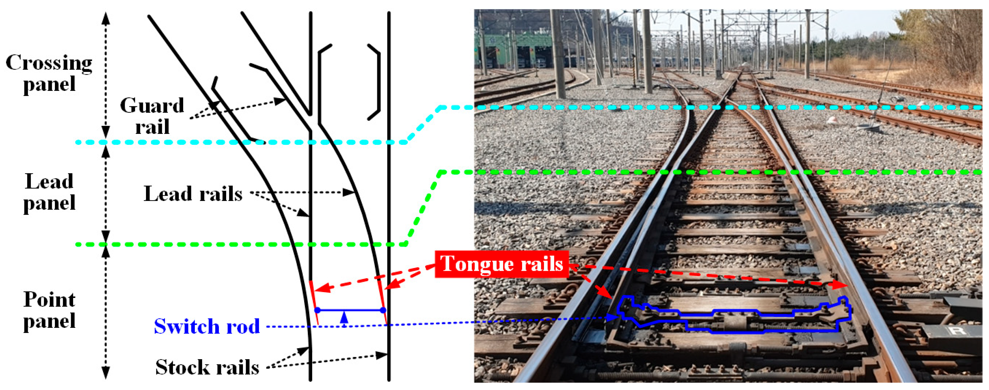
Figure 1. The structure and components of a railway turnout.
Energies 18 05149 g001
Figure 2. Photograph and operation of conventional RH system on railway turnout in Korea.
Energies 18 05149 g002
Figure 3. Overall configuration of the proposed IH system for railway turnouts.
Energies 18 05149 g003
Figure 4. Frequency status of Korean railway signaling frequencies.
Energies 18 05149 g004
Figure 5. Drawing of UIC 60 rail.
Energies 18 05149 g005
Figure 6. Circuit of the power conversion stage for the proposed IH system.
Energies 18 05149 g006
Figure 7. Three-dimensional drawing of power conversion stage.
Energies 18 05149 g007
Figure 8. The equivalent circuit of IMN and IH coils.
Energies 18 05149 g008
Figure 9. Modeling of optimal design IH coil.
Energies 18 05149 g009
Figure 10. Final IH coil prototype.
Energies 18 05149 g010
Figure 11. Controllers of the power conversion stage.
Energies 18 05149 g011
Figure 12. Photographs of setup in laboratory.
Energies 18 05149 g012
Figure 13. Experimental waveforms: (a) boost PFC stage operating alone under 100% load condition; (b) resonant inverter at operating frequencies of 250 kHz and 350 kHz.
Energies 18 05149 g013
Figure 14. Temperature curves in a room temperature experiment.
Energies 18 05149 g014
Figure 15. Photographs of outdoor experimental setup and results by time.
Energies 18 05149 g015
Figure 16. Measured snow cover on rail head by time.
Energies 18 05149 g016
Figure 17. Temperature curve of the actual snowfall experiment.
Energies 18 05149 g017
Figure 18. Photographs of field application test: (a) setup; (b) actual railway operation.
Energies 18 05149 g018
Figure 19. Part of KS C IEC60529:2013 test.
Energies 18 05149 g019
Figure 20. Input power of proposed deicing system.
Energies 18 05149 g020
Figure 21. Temperature curve of each system.
Energies 18 05149 g021
Table 1. Specifications in PFC stage.
ItemValueUnitNote
P r a t e 800WNominal rated output power
V i n , p k 311VMaximum input voltage
I i n , p k 5.14AMaximum input current
I i n 1.54ACurrent ripple 30%
V d c 350VOutput voltage
I o 2.29AOutput current
V d c 10.5VVoltage ripple 3%
L P F C 945μH Worst   condition   at   duty   D = 0.5
C P F C 577.43μFUnity power factor (PF = 1)
Table 2. Components in PFC stage.
ItemValueUnitNote
CoreOD358-High-Flux 60 μ
Turns131-0.81 φ, 3.5 A/mm2(Free convection)
Bmax0.61T-
P c o r e 3.96WCore loss of PFC Inductor
P c o i l 1.18WCoil loss of PFC Inductor
P d i o d e 1.63WIDH16G65C6
P c o n d 0.51WConduction loss@100% Load
P o n 0.43WSwitching loss@100% Load
P o f f 0.15W
P C o s s 0.31WCapacitive loss
P F E T 1.40WIPW60R090CFD7XKSA1
L P F C 945μHMeasured by IM3533, Hioki
C P F C 577.43μF450UF560MBN
Here, P d i o d e was calculated by multiplying the scaled forward voltage (0.712 V) by the average value of the maximum output current (2.28 A), which corresponds to 1.63 W under 100% load condition.
Table 3. Parameters for each system.
ItemValueUnitNote
c R H 500J/kg·°CRail heater
m R H 0.672kg
T R H 0.33°C/s
c I H 460J/kg·°CIH coil
m I H 0.255kg
T I H 0.49°C/s
Disclaimer/Publisher’s Note: The statements, opinions and data contained in all publications are solely those of the individual author(s) and contributor(s) and not of MDPI and/or the editor(s). MDPI and/or the editor(s) disclaim responsibility for any injury to people or property resulting from any ideas, methods, instructions or products referred to in the content.