Article

Transient Stability Control Method for Droop-Controlled Photovoltaics, Based on Power Angle Deviation Feedback †

1
Electric Power Research Institute of Guizhou Power Grid Co., Ltd., Guiyang 550002, China
2
The Collage of Electrical and Information Engineering, Hunan University, Changsha 410082, China
*
Author to whom correspondence should be addressed.
This paper is an extended version of our conference paper ‘Transient Stability Boundary of a Droop-Controlled Voltage Source Converter with Different Control Parameters’.
Energies 2025, 18(19), 5126; https://doi.org/10.3390/en18195126
Submission received: 24 July 2025 / Revised: 22 August 2025 / Accepted: 29 August 2025 / Published: 26 September 2025

Abstract

Distributed photovoltaic grid-connected converters adopting droop control can provide dual support for voltage and frequency in the distribution system. However, under fault conditions, droop-controlled inverters will face the problem of transient synchronization instability, and their transient characteristics are significantly affected by fault conditions, control parameter configurations, and other factors. Nevertheless, at present, the transient operation boundaries of droop inverters, considering key sensitive parameters, are unclear, and the transient stability control mechanism is lacking, which poses a threat to the safe and stable operation of distributed photovoltaic systems. To this end, this paper fully considers the influences of control parameters and fault severity and conducts a multidimensional quantitative characterization of the transient stability boundaries of droop-controlled inverters. Furthermore, a stability enhancement control structure for droop-controlled inverters, based on power angle deviation feedforward, is proposed, and an adaptive configuration method for feedforward coefficients is put forward to ensure the safe and stable operation of droop inverters at different fault sag depths. Finally, the accuracy of the theoretical analysis and the proposed control structure is verified through simulations and experiments.

1. Introduction

In recent years, a large number of distributed energy resources (DERs), such as photovoltaics (PVs), have been integrated into the power grid, posing significant challenges to mountainous distribution systems [1,2,3,4,5,6,7,8]. The inverter serves as the interface between distributed PVs and the power system. Currently, existing inverters are primarily categorized into two types: grid-forming inverters [9,10,11,12,13,14,15] and grid-following inverters [16,17,18,19].
Distributed PVs utilizing droop control can provide robust voltage and frequency support to mountainous distribution systems, leveraging their active-power-frequency and reactive-power-voltage droop characteristics [20]. However, once a fault occurs in the mountainous distribution system, droop-controlled inverters may experience transient synchronization instability similar to that of conventional synchronous generators, thereby diminishing their effectiveness in supporting the mountainous distribution system [9,21]. The stable operation of droop-controlled inverters is crucial for mountainous distribution systems. However, the analysis of their transient stability remains insufficiently comprehensive at present.
K. Rouzbehi et al. (2015) and H. Wu (2019) analyzed the impact of fault current limitation on the transient stability of droop-controlled inverters and found that certain current-limiting measures may degrade their transient stability performance, thereby further triggering transient instability [22,23]. Wu, H. (2018) and Zhao, F. (2020) compared the differences in transient characteristics between droop-controlled inverters and virtual synchronous generators (VSGs) [24,25]. However, the qualitative analysis of the transient characteristics of droop-controlled inverters ignored the influence of the reactive-voltage control loop, resulting in over-optimistic analytical outcomes. L. Huang (2019) employs Lyapunov’s direct method to derive the domain of attraction of droop-controlled inverters at different parameter settings yet fails to determine the maximum fault duration that the system can tolerate [26]. Existing studies have two main limitations: The transient analysis model of droop-controlled inverters is overly simplified, with the influence of the reactive-voltage control loop often neglected. On the other hand, the critical clearing angle (CCA) and critical clearing time (CCT) are two key indicators for characterizing system transient stability, yet insufficient attention has been paid to the role of the critical clearing time in assessing transient stability.
In terms of control, B. Fan (2022) proposes an adaptive virtual impedance control strategy, which enables flexible reactive power allocation and effectively mitigates power oscillation issues [27]. H. Mahmood (2015) proposes a reactive power compensation method that adjusts the voltage drop coefficient via adaptive voltage drop control [28]. The aforementioned studies modify the line impedance and voltage loop, respectively; however, during fault periods, power angle oscillations of droop-controlled inverters intensify. X. Xiong (2021) proposes an optimization method for the power angle control structure, based on the negative feedback of the voltage deviation in the reactive-power loop [29]. By introducing the voltage deviation to the control strategy of the active-power loop, this method reduces the active-power command and enhances the system stability. However, this method adds a coupling branch between the active-power-frequency control loop and the reactive-power-voltage control loop, which will change the system’s voltage construction capability to a certain extent.
In contrast, the control structure, based on power angle deviation feedforward, proposed in this paper, only improves the active-power-frequency control loop and does not add a coupling branch with the reactive-power-voltage loop. It achieves the safe and stable operation of the droop-controlled inverter without changing the original voltage construction capability of the droop-controlled inverter.
In this paper, the transient characteristics of droop-controlled distributed photovoltaics are analyzed both qualitatively and quantitatively, with the reactive-voltage control loop considered. Section 1 investigates the transient destabilization mechanism of droop-controlled inverters and qualitatively analyzes the impacts of different control parameters on their transient stability using phase plane diagrams. Section 2 analyzes the influence of the reactive-voltage control loop on droop-controlled inverters, thereby examining their transient stability. Section 3 quantitatively characterizes the CCA and CCT to describe the transient stability boundaries of droop-controlled inverters. Section 4 proposes a control structure incorporating power angle deviation feedforward to optimize the transient operation boundary of droop-controlled inverters. Section 5 validates the correctness of the theoretical analysis results presented in this paper through simulations.

2. Analysis of Transient Characteristics of Droop-Controlled Inverters

2.1. Basic Control of Droop-Controlled Inverters

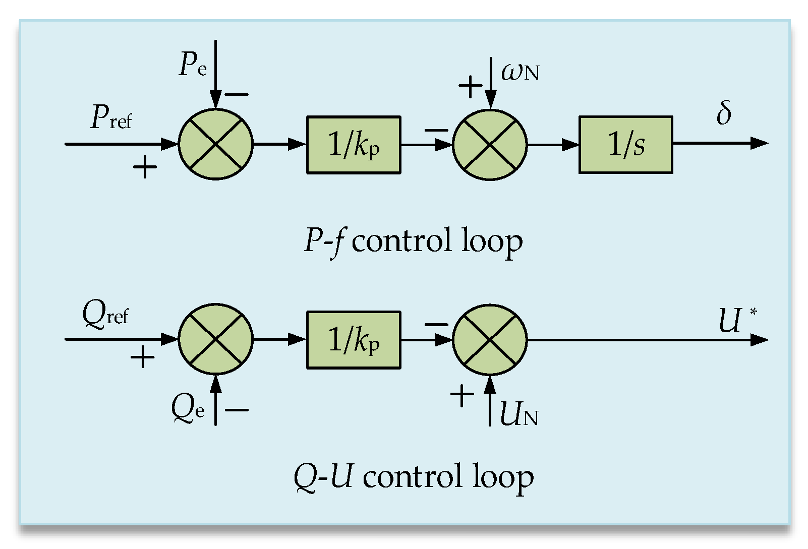
The circuit structure and control architecture of the droop-controlled distributed PV grid-connected system are illustrated in Figure 1 and Figure 2. In Figure 1, the system is composed of a photovoltaic array, a DC-side supporting capacitor (Udc), a grid-connected inverter (integrating a power electronic converter topology and a control module), filtering and line components (Lf, Rf, Cf, and Lg), and the power grid (ug). Figure 2 shows the control loop of the photovoltaic device, which consists of an active-power loop and a reactive-power loop. After the converter output side and the filter circuit, the AC current measurement (iabc) and AC voltage measurement (uabc) are set. Among them, (iabc) is used to extract the d-axis and q-axis components of the current (Id, Iq), which participate in the feedback regulation of the inner control loop of the converter; uabc is used to obtain the d-axis and q-axis components of the voltage (Ud, Uq) to support the operation of the voltage control loop.
In current research, the power loop of droop-controlled inverters is a primary factor affecting their transient stability; kp (the active-power-frequency droop coefficient) and kq (the reactive-power-voltage droop coefficient) are critical for preventing system instability.
The active-power-frequency control and reactive-power-voltage control equations of the droop-controlled inverter are given in Equations (1) and (2), respectively [27].
P ref P e = k p d δ d t d δ d t = ω ω N
Q ref Q e = k q ( U N U * )
where Pref and Qref are the power command values of the droop-controlled inverter; kp and kq are the droop coefficients for the active and reactive powers, respectively; ωn is the rated angular velocity, and ω is the actual angular velocity; Pe and Qe are the power output values of the droop-controlled inverter; and U* and UN are the voltage reference amplitude and the rated voltage amplitude of the droop-controlled inverter, respectively.
The power injected into the grid by the droop-controlled inverter can be expressed as follows [30]:
P e = 3 U U g s i n δ 2 X g
Q e = 3 U ( U U g cos δ ) 2 X g
where Xg = ωLg is the line reactance, Ug is the magnitude of the grid voltage, and U is the magnitude of the inverter output voltage.

2.2. Transient Power Angle Characteristics of Droop-Controlled Inverters

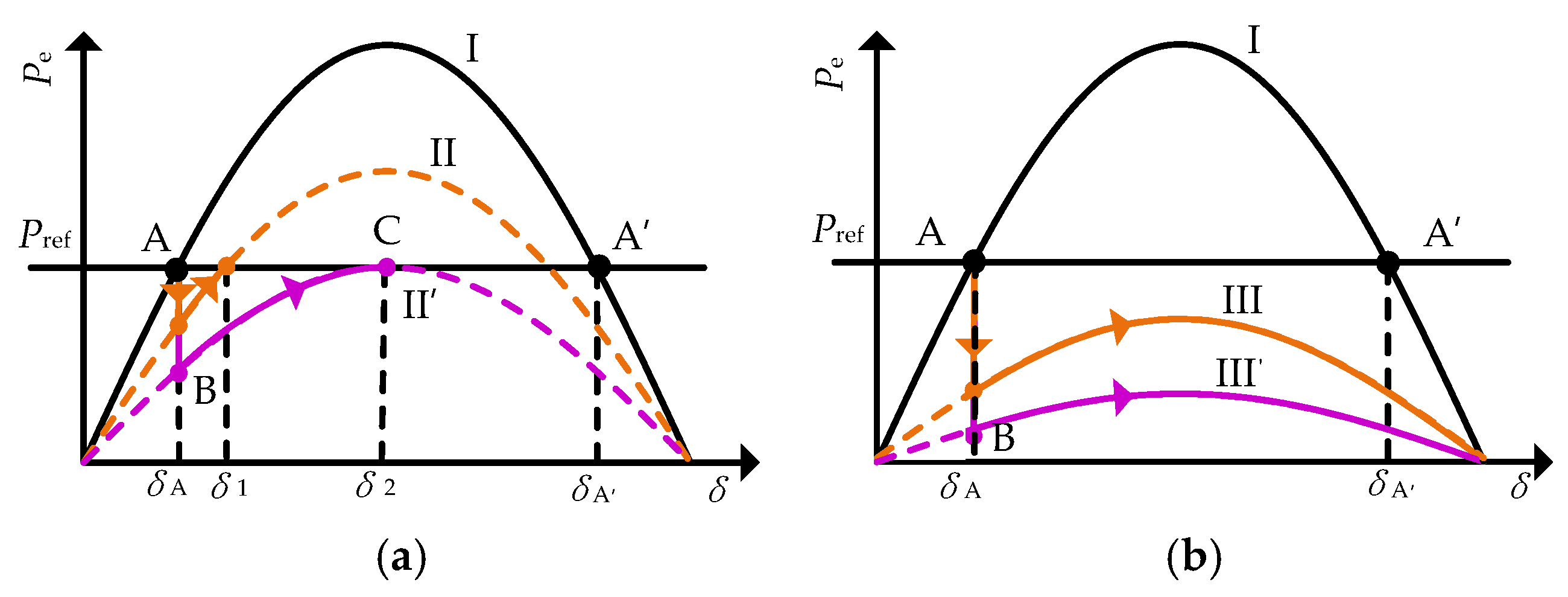
The active-power-frequency equation of the droop-controlled inverter is a first-order equation, and the input–output difference of the active power directly determines the rate of change in the power angle. According to Equation (1), the rate of change in the power angle is zero when the input–output active power satisfies PrefPe = 0. That is, during the fault period, the droop-controlled inverter can achieve transient stability if a power balance point exists; otherwise, transient instability will occur.
From Equations (1) and (3), the power angle curves of the droop-controlled inverter at different voltage sag depths can be obtained, as shown in Figure 3. Curve I represents the power angle curve under rated conditions, while curves II, II′, III, and III′ correspond to the power angle curves at different grid fault depths. Points A and A′ are power balance points, where A is a stable equilibrium point, and A′ is an unstable equilibrium point.
Figure 3a indicates the existence of a power balance point during a fault. Taking curve II′ as an example, after the fault is cleared, the system operating point jumps from point A to point B, moves along curve II′, and finally achieves transient stable operation at point C. The system then operates at point C, which is a power balance point. Figure 3b presents the scenario where there is no power balance point during the fault. Initially, the system operates at point A. After the fault occurs, the power angle continues to increase and eventually becomes unstable because PrefPe > 0. In other words, if there is no power equilibrium point in the system during a fault, the fault must be cleared before the power angle reaches δA′; otherwise, the droop-controlled inverter will become unstable, at least during the first oscillation cycle.

3. Qualitative Assessment of the Transient Stability Performance of Droop-Controlled Inverters

Section 2.2 analyzes the transient power angle characteristics of the droop-controlled inverter, but the influences of control parameters on its transient stability remain unclear. Based on this, this section qualitatively analyzes the effects of different control parameters on the transient stability of the droop-controlled inverter by considering the reactive-voltage control loop.
It is shown that the transient stability of the droop-controlled inverter mainly depends on the external power control loop. Therefore, when analyzing the transient stability of the droop-controlled inverter, it can be assumed that U can track U* without error [22,23], i.e.,
U = U *
Combining Equations (2), (4) and (5) yields the magnitude of the output voltage of the droop-controlled inverter as Equation (6). Substituting Equation (6) into Equation (3) yields the output active power of the droop-controlled inverter, considering the reactive-voltage control loop, as Equation (7).
To demonstrate the influences of different system control parameters on the transient stability of the droop-controlled inverter more intuitively, a phase plane diagram is used to describe the transient trajectory of the droop-controlled inverter during the fault process. The active-frequency control (Equation (8)), considering the reactive-voltage droop control, is obtained by substituting Equation (7) into Equation (1) [31].
U = 1 6 × 3 U g cos δ 2 k q X g + ( 3 U g cos δ 2 k q X g ) 2 + 24 X g ( k q U N + Q ref )
P e = U g s i n δ 4 X g × 3 U g c o s δ 2 k q X g + ( 3 U g c o s δ 2 k q X g ) 2 + 24 X g ( k q U N + Q ref )
d δ d t = P ref a sin δ × 3 U g cos δ b + ( 3 U g cos δ b ) 2 + c k p
where a = Ug/(4Xg), b = 2kqXg, and c = 24Xg (kqUN + Qref).
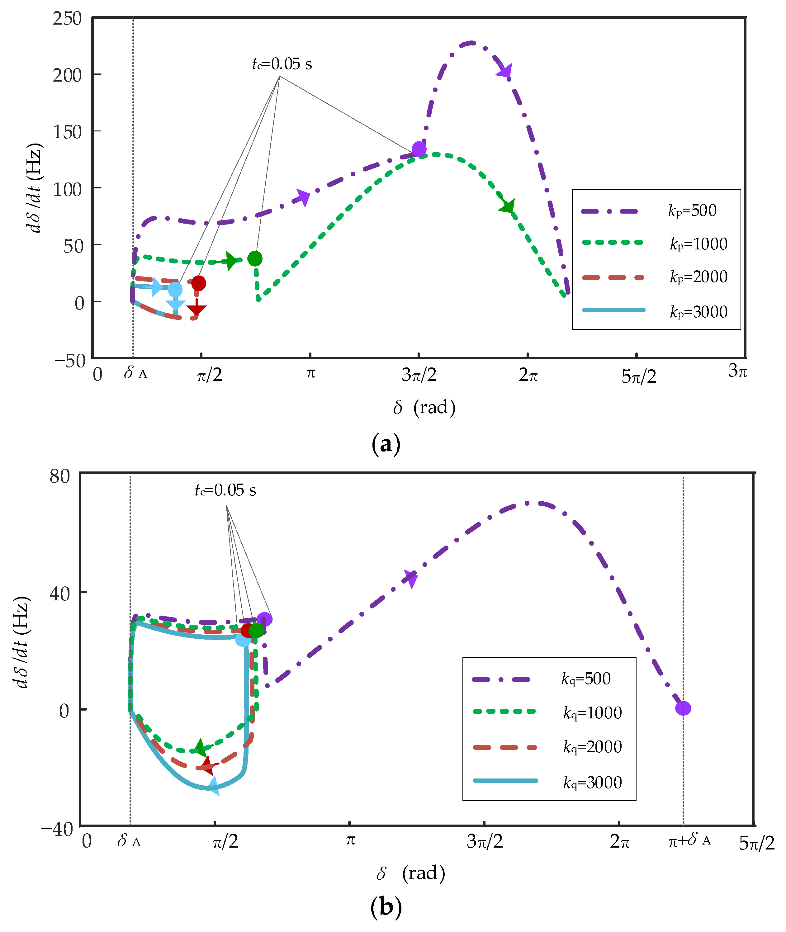
When a short-term fault occurs in the system, the fault does not persist, so the transient behavior of the droop-controlled inverter during fault recovery is worth considering. When a fault occurs in the system, the grid voltage drops to 0.2 pu, and the fault lasts for 0.05 s before being cleared. The transient trajectory of the droop-controlled inverter is shown in Figure 4.
Figure 4a shows the transient operation trajectory of droop-controlled distributed PV systems with different values of kp. As kp decreases, the rate of change in the power angle increases, the transient stability performance of the system gradually deteriorates, and the system becomes transiently unstable when kp decreases from 3000 to 1000. Figure 4b shows the transient trajectory of droop-controlled distributed PV systems with different values of kq. As kq decreases, the transient stability performance of the system gradually deteriorates, and when kq decreases from 3000 to 500, the system becomes transiently unstable.

4. Quantitative Characterization of Transient Stable Operation Boundaries

Section 3 qualitatively analyzes the effects of different control parameters on the transient stability of the droop-controlled inverter. However, the transient stability boundary of the droop-controlled inverter cannot be directly derived from the results of qualitative analysis; for this reason, this chapter will quantitatively characterize the transient stability boundary of the droop-controlled inverter.

4.1. Quantitative Characterization of CCA

Based on the analysis in Section 3, it can be seen that the sag inverter can remain transiently stable when the system is in the presence of a power balance point, even if the fault persists. If the sag inverter power angle curve during the fault (Equation (9)) has an intersection with the active-power command value of the sag inverter, the sag inverter will not have CCA, and the system will constantly be able to maintain transient stable operation [26].
P e = U g s i n δ 4 X g × 3 U g c o s δ 2 k q X g + ( 3 U g c o s δ 2 k q X g ) 2 + 24 X g ( k q U N + Q ref ) P e = P ref
CCA = δ k = U g / U gN P ref = P e = asin δ × 3 U gN cos δ b + ( 3 U gN cos δ b ) 2 + c
If the power angle curve of the droop-controlled inverter during a fault (Equation (9)) does not intersect with its active-power command value, the fault must be cleared within a specified time; otherwise, the system will experience transient instability. Since the active-frequency equation of the droop-controlled inverter is a first-order equation, the CCA corresponds to the power angle at the unstable equilibrium point. Due to the reactive-voltage control loop, the power angle curve of the droop-controlled inverter is not a standard sinusoidal curve [23]. Therefore, the CCA cannot be simply obtained using the formula CCA = π − δA. Based on previous studies, the CCA is derived by solving Equation (10).
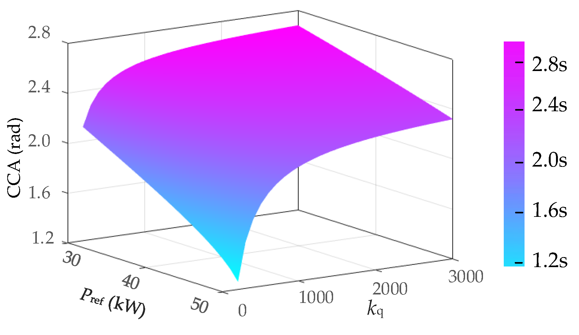
According to Equation (10), the CCA of the droop-controlled inverter, considering different reactive-voltage droop coefficients (kq) and active-power command values (Pref), is shown in Figure 5. It can be observed that the CCA increases with increases in kq; in addition, as the active-power command value increases, the difference between the input and output active powers gradually widens during the fault. When the active-power output is lower than the active-power command value, the voltage source converter (VSC) becomes transiently unstable. If the power angle (δC) at the time of the fault clearing satisfies δC < CCA, the droop-controlled inverter will achieve transient stability after the fault is cleared; conversely, if δC > CCA, the droop-controlled inverter will experience first-swing instability when the fault is cleared.

4.2. Quantitative Characterization of CCT

CCT refers to the time interval corresponding to the power angle moving from δA to the CCA. In this paper, numerical and iterative calculations are used to determine the CCT. Based on Equation (11), the numerical solutions for the time series [t0, t1, t2, …, ti] and the power angle sequence [δA, δB, δC, …, δi] can be obtained using the Runge–Kutta algorithm [29].
t 0 = 0 δ 0 = δ A d δ d t = P ref a sin δ × 3 U g cos δ b + ( 3 U g cos δ b ) 2 + c k p
In Equation (11), t0 = 0 and δ0 = δA are the initial values of the time series and the power angle series, respectively. As can be seen from Figure 3, δ0 (i.e., δA) is almost independent of the control parameters. To simplify the calculation, it can be assumed that δ0 = arcsin (2PrefXg/(3UgUN)).
The iterative calculation process of the CCT is shown in Figure 6.
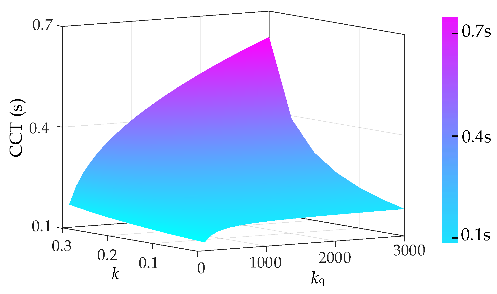
By adopting the above numerical and iterative calculation methods, the CCTs of the droop-controlled inverter, for different active-frequency droop coefficients (kp), reactive-voltage droop coefficients (kq), and grid voltage droop coefficients (k), are shown in Figure 7.
In Figure 7, increases in both kq and k lead to an increase in the CCT. The effect of k has been explained earlier. As a reactive-voltage droop coefficient, kq influences the CCT by simultaneously altering the CCA and the rate of change in the power angle. Specifically, as kq increases, the CCA increases while the rate of change in the power angle decreases, collectively resulting in a longer CCT. It is noteworthy that, as observed in Figure 3, the influence of kq on the active power output of the droop-controlled inverter diminishes with increasing kq; similarly, Figure 7 clearly shows that the effect of kq on the CCT also weakens as kq increases.

5. Power Angle Deviation Feedforward Control

5.1. Power Angle Deviation Feedforward Control Structure

During a fault, as the grid voltage fault depth varies, the rate of change in the power angle alters; this change in the power angle further induces a variation in its rate of change, thereby deteriorating the system stability performance. However, if the characteristics of the power angle variation during the fault can be utilized and fed back to the active-power loop, the transient stability of the droop-controlled inverter during the fault can be improved, thus ensuring system stability. As shown in Figure 8, by modifying the active-frequency control loop of the droop-controlled inverter, the power angle deviation value of the system output is fed back to the active-power loop, thereby optimizing the stability boundary of the droop-controlled inverter.
After adding the power angle feedforward control, the active-power loop of the droop-controlled inverter is modified as follows:
P r e f P e K 1 δ δ N = k p d δ d t
where K1 is the power angle deviation feedforward coefficient.

5.2. Design of the Power Angle Deviation Feedforward Coefficient

The active power output of the droop-controlled inverter during a fault is as follows:
P e F = U g F s i n δ 4 X g × 3 U g F c o s δ 2 k q X g + ( 3 U g F c o s δ 2 k q X g ) 2 + 24 X g ( k q U N + Q ref )
The inverter stabilizes when dδ/dt = 0; at this point, the following relationship holds:
P r e f K 1 δ δ N = P e F
As shown in Figure 9, during the fault, the droop-controlled inverter under conventional control will experience transient instability. For the droop-controlled inverter with the addition of the power angle deviation feedforward control, its equivalent active-power command value (PrefK1(δδN)) decreases. If K1 is reasonably selected, the equivalent active-power command value of the droop-controlled inverter’s power angle curve will intersect with its output active power; at this point, the droop-controlled inverter transitions from transient instability to transient stability.
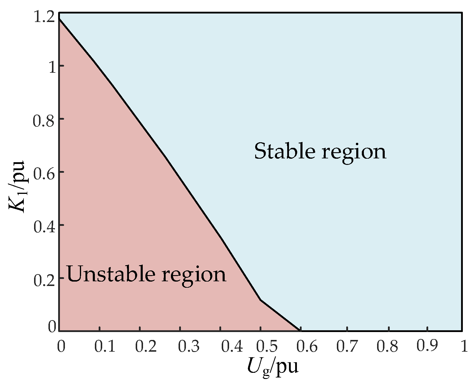
As shown in Figure 9, the blue curve represents the power angle curve of the droop-controlled inverter before the fault, while the purple curve denotes that after the fault occurs. By determining the power angle (δmax) corresponding to the maximum active power output of the droop-controlled inverter during a fault, if the condition PrefK1(δmaxδN) is satisfied at this point, there will be at least one intersection between the equivalent active-power command value and the output active power. From this condition, the value of K1 can be derived, and the relationship between the grid fault voltage (UgF) and K1 is plotted in Figure 10. All the K1 values within the stable region can ensure the stability of the droop-controlled inverter during the corresponding grid fault. It can be observed that when kq = 800, the droop-controlled inverter will not undergo transient instability as long as the grid voltage dips to 0.6 pu or higher.

6. Simulation Results

To verify the accuracy of the conclusions derived from the theoretical analysis in this paper, a MATLAB 2022a/SIMULINK simulation model (as shown in Figure 1) is established, and hardware-in-the-loop (HIL) experiments are conducted. The main simulation parameters are presented in Table 1, and the parameters listed in this table shall be consistently applied throughout the entire manuscript.
To ensure the accuracy and efficiency of the simulation, the key parameters of the MATLAB/SIMULINK model are configured as follows: a step size of 5 × 10⁻⁶, a converter-switching frequency of 10 kHz, and the ode45 solver (a variable-step explicit Runge–Kutta solver commonly used for transient analysis) are adopted to solve the system’s differential equations. The first scenario tests the performance of the droop-controlled inverter when the grid voltage drops to 0.30 pu at 1.0 s. The impacts of the different control parameters on the transient stability of the droop-controlled inverter are illustrated in Figure 11. From the analysis in Section 4, the CCA and CCT of the droop-controlled inverter under this condition are 2.70 rad and 0.51 s, respectively. To verify the correctness of the calculated transient stability boundary of the droop-controlled inverter, the fault durations set in the simulation are 0.5 s and 0.53 s. As shown in Figure 11a, when the fault duration is 0.5 s, the power angle reaches 2.52 rad; since the fault is cleared within the transient stability boundary, the droop-controlled inverter achieves transient stability after the fault is removed. Figure 11b shows that when the fault duration is 0.53 s, the power angle reaches 2.73 rad. As the fault is cleared after exceeding the transient stability boundary, the droop-controlled inverter loses transient stability after the fault. These simulation results confirm the correctness of the transient stability boundary analyzed in Section 4.
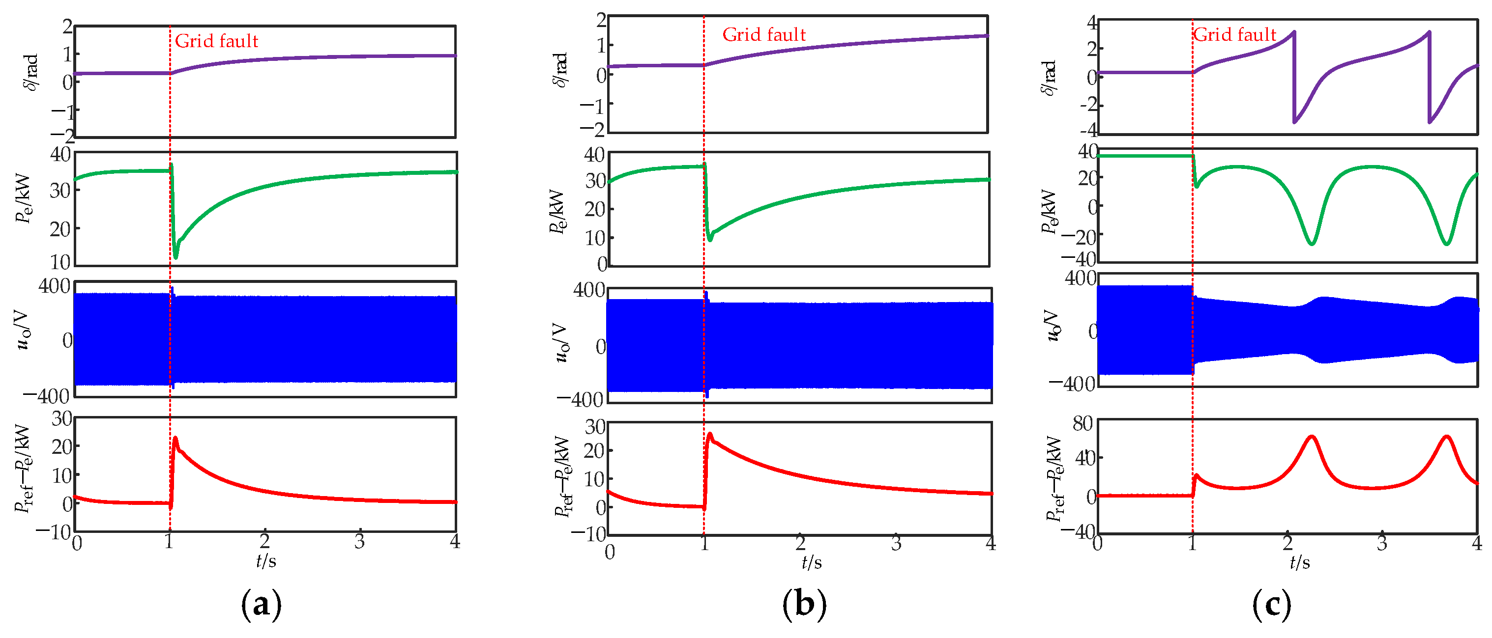
Figure 12 presents the simulation comparison results of the droop-controlled inverter for different configurations of control coefficients kp and kq. In Figure 12a, with the parameter configuration of kp = 3000 and kq = 1500, after a fault occurs, the power angle of the inverter fluctuates slightly, and the active power quickly recovers to stability after a brief drop. By comparing Figure 12a with Figure 12b, it can be observed that the response speed of the transient stability recovery in Figure 12b is significantly slower, which indicates that an increase in kp will reduce the transient evolution speed of the droop inverter. In Figure 12c, as kq decreases, the power angle, active power, and output voltage exhibit continuous oscillation characteristics, and the inverter becomes unstable—this demonstrates that a decrease in kq will reduce the transient stability of the inverter.
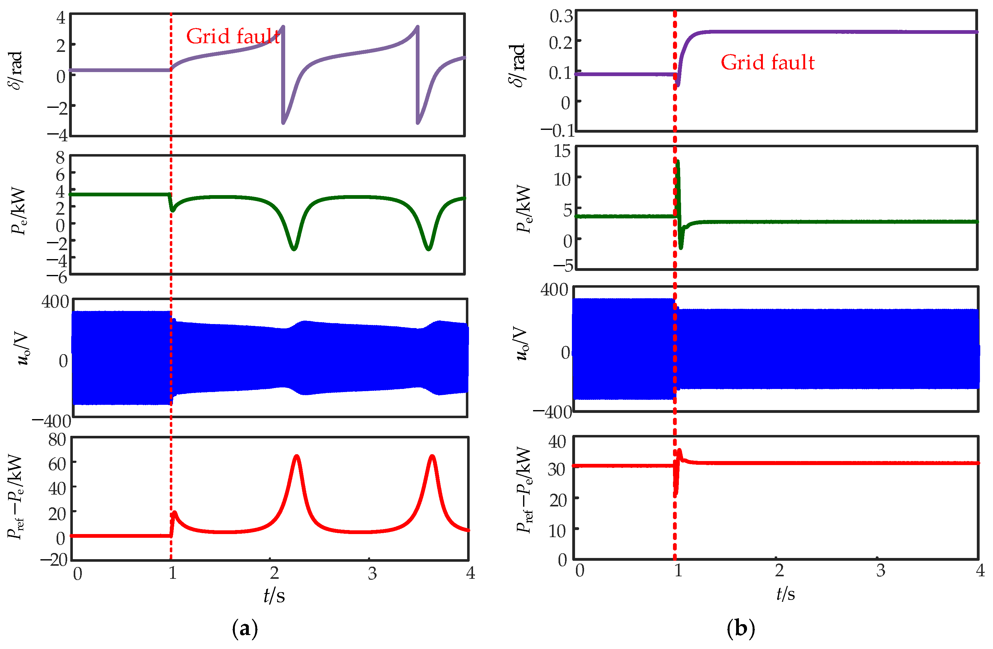
The second scenario is to test the performance of the droop inverter when a fault occurs in the grid voltage at the 1.0 s moment. Figure 13 represents the comparison of simulation results with and without power angle feedforward control when the grid voltage drops to 0.3 pu. Figure 13a shows that the power angle change rate of the droop inverter under the conventional control increases during the occurrence of a fault, and the output active power, active-power command value, and active-power difference undergo cyclic oscillation. Figure 13b shows that the power angle change rate of the droop inverter, after adding the power angle feedforward control, decreases compared to that of the conventional control, and the output active power, active-power command value, and active-power difference undergo periodic oscillation. Figure 13b shows that the power angle change rate of the droop inverter, after adding the power angle feedforward control, reduces compared to that of the conventional control, and the output active power, active-power command value, and active-power difference value are stabilized. Figure 14 represents the comparison of simulation results with and without power angle feedforward control when the grid voltage drops to 0.2 pu. Figure 14a indicates that the power angle change rate of the droop inverter under the conventional control increases when a fault occurs, and the output active power, its command value, and the difference between the two show periodic fluctuations. Figure 14b indicates that the power angle change rate of the droop inverter decreases, after adding the power angle feedforward control, compared with that of the conventional control, and the output active power, its command value, and the deviations of both tend to be stabilized. Additionally, the periodic oscillation phenomenon disappears so that the inverter can still maintain stable operation during faults, which greatly improves the system’s anti-interference capability and operation reliability.
Figure 15 presents the experimental results of the VSC with different control methods. It can be observed from the figure that the VSC with traditional control loses transient stability when the grid voltage drops to 0.3 pu. In contrast, the VSC with power angle deviation feedforward control maintains transient stability. These experimental results are consistent with the simulation and theoretical analysis results, which verifies the correctness of the theoretical analysis and the proposed method in this paper.

7. Conclusions

To address the issue of the transient instability of droop inverters under fault conditions, this paper proposes a droop control stability enhancement structure, and the following conclusions are verified through simulations and hardware-in-the-loop (HIL) experiments:
(1)
Control parameters have significant impacts on the transient stability boundary of droop inverters. Increasing the active-power-frequency/voltage droop coefficient can improve the CCT of droop inverters, while increasing the reactive-power-voltage droop coefficient can simultaneously optimize both the CCA and CCT of droop inverters;
(2)
The control method for droop-controlled inverters, based on power angle deviation feedforward, proposed in this paper, can automatically feedback power angle deviation information and adaptively configure the feedforward coefficient according to fault depth, thereby ensuring the transient stable operation of the inverter at different grid fault depths;
(3)
The stability control strategy, based on power angle deviation, proposed in this paper, can reduce the impacts of grid disturbances on photovoltaic converters without the need for additional hardware equipment, solve the problem of frequent shutdowns of photovoltaic converters (caused by voltage disturbances), and improve the economy of new energy generation grid connections;
(4)
With an increase in the proportion of new energy grid connections, exploring the scalability of the power angle deviation feedforward control, proposed in this paper, in photovoltaic cluster systems and solving the stability problem in large-scale new energy generation scenarios will be the focus of the next work.

Author Contributions

Methodology, Y.Z. and Z.X.; Software, L.H.; Investigation, Z.X.; Writing—original draft, Y.Z., Z.X., L.H., Q.G., C.L. and K.C.; Writing—review & editing, Y.Z.; Supervision, C.L. All authors have read and agreed to the published version of the manuscript.

Funding

This research was funded by Guizhou Power Grid Co., Ltd. Electric Power Research Institute Science and Technology Project (GZKIXM20222409). And The APC was funded Guizhou Power Grid Co., Ltd. Electric Power Research Institute Science and Technology Project (GZKIXM20222409).

Data Availability Statement

The original contributions presented in the study are included in the article, further inquiries can be directed to the corresponding author.

Conflicts of Interest

Authors Youzhuo Zheng, Long Hua, Chun Li and Kailei Chen were employed by the company Electric Power Research Institute of Guizhou Power Grid Co., Ltd. The authors declare that this study received funding from Guizhou Power Grid Co., Ltd. The funder was not involved in the study design, collection, analysis, interpretation of data, the writing of this article or the decision to submit it for publication. The remaining authors declare that the research was conducted in the absence of any commercial or financial relationships that could be construed as a potential conflict of interest.

References

  1. Yang, X.; Song, Y.; Wang, G.; Wang, W. A Comprehensive Review on the Development of Sustainable Energy Strategy and Implementation in China. IEEE Trans. Sustain. Energy 2010, 2, 57–65. [Google Scholar] [CrossRef]
  2. Yang, F.; Sun, Q.; Han, Q.-L.; Wu, Z. Cooperative Model Predictive Control for Distributed Photovoltaic Power Generation Systems. IEEE J. Emerg. Sel. Top. Power Electron. 2016, 2, 414–420. [Google Scholar] [CrossRef]
  3. Lv, X.; Qiao, F.; Sun, Y.; Dinavahi, V.; Liu, P.X. Improved Memory Event-Triggered Load Frequency Control in Multi-Area Power System with Renewable Energy. IEEE Trans. Circuits Syst. II Express Briefs 2024, 1, 311–315. [Google Scholar] [CrossRef]
  4. Zhang, W.; Li, T.; Wang, X.; Liu, Q.; Liu, S.; Luo, M.; Dai, Z. Protection Principle of DC Line Based on Fault Component of Line Mode Voltage with Current-Limiting Reactor. Energies 2025, 18, 4271. [Google Scholar] [CrossRef]
  5. Lee, S.; Kim, G.; Son, S.; Lee, J. Comparative Analysis of the Substitution Effect of Smart Inverter-Based Energy Storage Systems on the Improvement of Distribution System Hosting Capacity Using Vertical Photovoltaic Systems. Energies 2025, 18, 4307. [Google Scholar] [CrossRef]
  6. Mensah Akwasi, A.; Chen, H.; Liu, J.; Duku, O.-A. Hybrid Adaptive Learning-Based Control for Grid-Forming Inverters: Real-Time Adaptive Voltage Regulation, Multi-Level Disturbance Rejection, and Lyapunov-Based Stability. Energies 2025, 18, 4296. [Google Scholar] [CrossRef]
  7. Zhang, Q.; Li, Y.; Ding, Z.; Xie, W.; Li, C. Self-Adaptive Secondary Frequency Regulation Strategy of Micro-Grid with Multiple Virtual Synchronous Generators. IEEE Trans. Ind. Appl. 2020, 5, 6007–6018. [Google Scholar] [CrossRef]
  8. Najafabadi, S.R.K.; Fani, B.; Sadeghkhani, I. Optimal Determination of Photovoltaic Penetration Level Considering Protection Coordination. IEEE Syst. J. 2022, 2, 2121–2124. [Google Scholar] [CrossRef]
  9. Ghosh, S.; Bohra, A.; Dutta, S.; Verma, S. Integration Strategies for Large-Scale Renewable Interconnections with Grid Forming and Grid Following Inverters, Capacitor Banks, and Harmonic Filters. Energies 2025, 18, 3934. [Google Scholar] [CrossRef]
  10. Li, C.; Yang, Y.; Mijatovic, N.; Dragicevic, T. Frequency Stability Assessment of Grid-Forming VSG in Framework of MPME with Feedforward Decoupling Control Strategy. IEEE Trans. Ind. Electron. 2022, 7, 6903–6913. [Google Scholar] [CrossRef]
  11. Liu, C.; Chu, Z.; Duan, Z.; Zhang, Y. VSG-Based Adaptive Optimal Frequency Regulation for AC Microgrids with Nonlinear Dynamics. IEEE Trans. Autom. Sci. Eng. 2025, 22, 1471–1482. [Google Scholar] [CrossRef]
  12. Samanta, S.; Yang, B.; Seo, G.-S. Stability Analysis of Power Systems with High Penetration of State-of-the-Art Inverter Technologies. Energies 2025, 18, 3645. [Google Scholar] [CrossRef]
  13. Chen, S.; Sun, Y.; Hou, X.; Han, H.; Fu, S.; Su, M. Quantitative Parameters Design of VSG Oriented to Transient Synchronization Stability. IEEE Trans. Power Syst. 2023, 5, 4978–4981. [Google Scholar] [CrossRef]
  14. Meng, X.; Liu, J.; Liu, Z. A Generalized Droop Control for Grid-Supporting Inverter Based on Comparison Between Traditional Droop Control and Virtual Synchronous Generator Control. IEEE Trans. Power Electron. 2019, 6, 5416–5438. [Google Scholar] [CrossRef]
  15. Yu, J.; Lin, X.; Song, D.; Yu, R.; Li, Y.; Su, M. Harmonic Instability and Amplification for Grid-Connected Inverter with Voltage Harmonics Compensation Considering Phase-Locked Loop. IEEE J. Emerg. Sel. Top. Power Electron. 2020, 4, 3944–3959. [Google Scholar] [CrossRef]
  16. Ding, Y.; Gao, F.; Khan, M.M. Transient Stability Analysis of Microgrid Considering Impact of Grid-Following Converter’s Current Controller. IEEE Trans. Power Electron. 2024, 8, 9100–9105. [Google Scholar] [CrossRef]
  17. Shuai, Z.; Shen, C.; Liu, X.; Li, Z.; Shen, Z.J. Transient Angle Stability of Virtual Synchronous Generators Using Lyapunov’s Direct Method. IEEE Trans. Smart Grid 2019, 4, 4648–4661. [Google Scholar] [CrossRef]
  18. Deng, Y.; Tao, Y.; Chen, G.; Li, G.; He, X. Enhanced Power Flow Control for Grid-Connected Droop-Controlled Inverters with Improved Stability. IEEE Trans. Ind. Electron. 2017, 7, 5919–5929. [Google Scholar] [CrossRef]
  19. Belgacem, M.; Khatir, M.; Djehaf, M.A.; Bouddou, R.; Behamida, F. Analysis and impacts of implementing droop control in Multi-Terminal VSC-HVDC under the steady state and Transient stability. In Proceedings of the 2020 International Conference on Electrical and Information Technologies (ICEIT), Rabat, Morocco, 4–7 March 2020; pp. 1–6. [Google Scholar]
  20. Taul, M.G.; Wang, X.; Davari, P.; Blaabjerg, F. An Overview of Assessment Methods for Synchronization Stability of Grid-Connected Converters Under Severe Symmetrical Grid Faults. IEEE Trans. Power Electron. 2019, 10, 9655–9670. [Google Scholar] [CrossRef]
  21. Xin, H.; Huang, L.; Zhang, L.; Wang, Z.; Hu, J. Synchronous Instability Mechanism of P-f Droop-Controlled Voltage Source Converter Caused by Current Saturation. IEEE Trans. Power Syst. 2016, 6, 5206–5207. [Google Scholar] [CrossRef]
  22. Rouzbehi, K.; Miranian, A.; Candela, J.I.; Luna, A.; Rodriguez, P. A Generalized Voltage Droop Strategy for Control of Multiterminal DC Grids. IEEE Trans. Ind. Appl. 2015, 1, 607–618. [Google Scholar] [CrossRef]
  23. Wu, H.; Wang, X. Design-Oriented Transient Stability Analysis of Grid-Connected Converters with Power Synchronization Control. IEEE Trans. Ind. Electron. 2019, 8, 6473–6482. [Google Scholar] [CrossRef]
  24. Wu, H.; Wang, X. Transient angle stability analysis of grid-connected converters with the first-order active power loop. In Proceedings of the 2018 IEEE Applied Power Electronics Conference and Exposition (APEC), San Antonio, TX, USA, 4–8 March 2018; IEEE: New York, NY, USA, 2018. [Google Scholar]
  25. Zhao, F.; Shuai, Z.; Shen, C.; Cheng, H.; Shen, Y.; Peng, Y. Comparison of transient angle stability between virtual synchronous generator and droop-controlled inverter. In Proceedings of the 2020 IEEE Applied Power Electronics Conference and Exposition (APEC), New Orleans, LA, USA, 15–19 March 2020; IEEE: New York, NY, USA, 2020. [Google Scholar]
  26. Huang, L.; Xin, H.; Wang, Z.; Zhang, L.; Wu, K.; Hu, J. Transient Stability Analysis and Control Design of Droop-Controlled Voltage Source Converters Considering Current Limitation. IEEE Trans. Smart Grid 2019, 1, 578–591. [Google Scholar] [CrossRef]
  27. Fan, B.; Li, Q.; Wang, W.; Yao, G.; Ma, H.; Zeng, X. A Novel Droop Control Strategy of Reactive Power Sharing Based on Adaptive Virtual Impedance in Microgrids. IEEE Trans. Ind. Electron. 2022, 11, 11335–11347. [Google Scholar] [CrossRef]
  28. Mahmood, H.; Michaelson, D.; Jiang, J. Reactive Power Sharing in Islanded Microgrids Using Adaptive Voltage Droop Control. IEEE Trans. Smart Grid 2015, 6, 3052–3060. [Google Scholar] [CrossRef]
  29. Xiong, X.; Wu, C.; Blaabjerg, F. Effects of Virtual Resistance on Transient Stability of Virtual Synchronous Generators Under Grid Voltage Sag. IEEE Trans. Ind. Electron. 2021, 69, 4754–4764. [Google Scholar] [CrossRef]
  30. Peng, J.C.-H.; Raman, G.; Soon, J.L.; Hatziargyriou, N.D. Droop-Controlled Inverters as Educational Control Design Project. IEEE Trans. Power Syst. 2021, 37, 1623–1633. [Google Scholar] [CrossRef]
  31. Ge, P.; Xiao, F.; Tu, C.; Guo, Q.; Xiao, Z.; Xie, W. Transient power angle control for a droop-controlled voltage source converter considering fault current limitation. CSEE J. Power Energy Syst. 2022, 8, 968–970. [Google Scholar] [CrossRef]
  32. Ge, P.; Tu, C.; Xiao, F.; Xiao, Z.; Hou, Y.; Chen, L. Transient Stability Boundary of a Droop-Controlled Voltage Source Converter with Different Control Parameters. In Proceedings of the 2022 International Conference on Power Energy Systems and Applications (ICoPESA), Singapore, 25–27 February 2022; pp. 286–291. [Google Scholar]
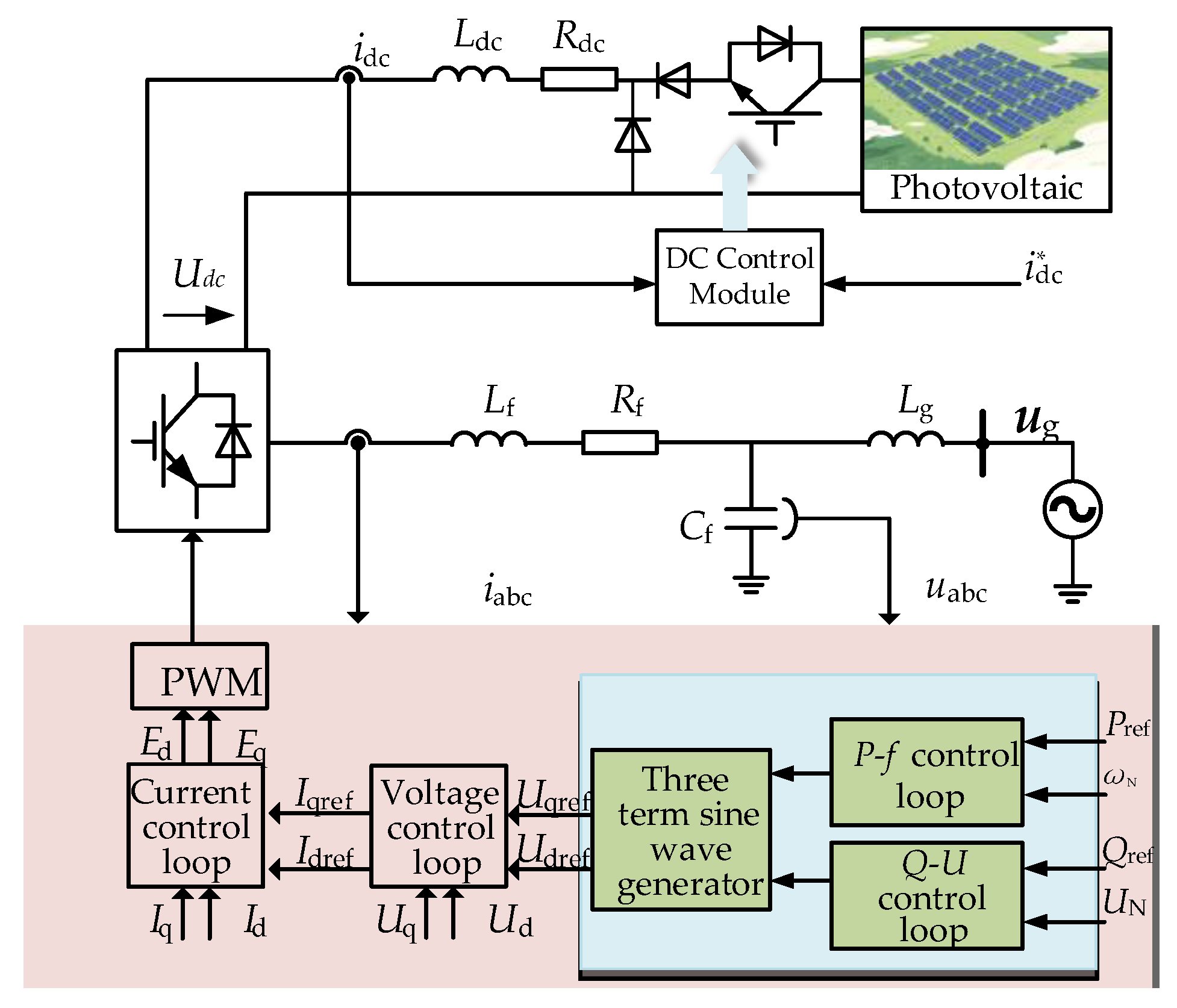
Figure 1. Control diagram of a VSC connecting to the infinite grid.
Energies 18 05126 g001
Figure 2. Droop-controlled distributed photovoltaic control framework.
Energies 18 05126 g002
Figure 3. P-δ curves of a droop-controlled VSC. (a) Power angle curve with power balance points; (b) Power angle curve without power balance points.
Energies 18 05126 g003
Figure 4. Phase portraits of a droop-controlled VSC with different control parameters: (a) kq = 1500; (b) kp = 3000.
Energies 18 05126 g004
Figure 5. CCA graphs with different parameters.
Energies 18 05126 g005
Figure 6. Iterative calculation procedure for the CCT [32].
Energies 18 05126 g006
Figure 7. CCT graphs for different parameters.
Energies 18 05126 g007
Figure 8. Feedforward control loop based on power angle deviation.
Energies 18 05126 g008
Figure 9. Power angle curve with added power angle deviation feedforward.
Energies 18 05126 g009
Figure 10. K1 value range.
Energies 18 05126 g010
Figure 11. Simulation results of the droop inverter when the grid voltage drops to 0.30 pu: (a) tc = 0.60 s and δc = 1.6 rad; (b) tc = 0.65 s and δc = 1.6 rad.
Energies 18 05126 g011
Figure 12. Simulation comparison diagrams for different parameter configurations: (a) kp = 3000 and kq = 1500; (b) kp = 4000 and kq = 1500; (c) kp = 3000 and kq = 1000.
Energies 18 05126 g012
Figure 13. Simulation results of the droop inverter for the grid voltage dropping to 0.30 pu: (a) traditional control; (b) power angle deviation feedforward control.
Energies 18 05126 g013
Figure 14. Simulation results of the droop inverter for the grid voltage dropping to 0.20 pu: (a) traditional control; (b) power angle deviation feedforward control.
Energies 18 05126 g014
Figure 15. Experimental results of the VSC. (a) Traditional VSC; (b) VSC with power angle deviation feedforward control.
Energies 18 05126 g015
Table 1. Simulation parameters.
ParameterMeaningAssignment
Udc/VDC voltage800
UgN/VGrid nominal voltage311
Cf/uFFilter capacitor50
Udc/VDC voltage800
UgN/VGrid nominal voltage311
Cf/uFFilter capacitor50
kipProportional coefficient of the current loop2
kiiIntegral coefficient of the current loop200
kupProportional coefficient of the voltage loop0.55
kuiIntegral coefficient of the volt-age loop100
kqReactive-power droop coefficient1500
kpActive-power droop coefficient3000
Disclaimer/Publisher’s Note: The statements, opinions and data contained in all publications are solely those of the individual author(s) and contributor(s) and not of MDPI and/or the editor(s). MDPI and/or the editor(s) disclaim responsibility for any injury to people or property resulting from any ideas, methods, instructions or products referred to in the content.