Abstract
The fast and accurate calculation of the internal temperature rise in the oil-immersed transformer is the premise to realize the thermal health management and load energy evaluation of the in-service transformer. In view of the influence of nanofluids on the heat transfer process of transformer, a numerical simulation algorithm based on lattice Boltzmann method (LBM) and finite difference method (FDM) is proposed to study the heat and mass transfer process inside nano-modified oil-immersed transformer. Firstly, the D2Q9 lattice model is used to solve the fluid and thermal lattice Boltzmann equations inside the oil-immersed transformer at the mesoscopic scale, and the temperature field and velocity field are obtained by macroscopic transformation. Secondly, the electric field distribution inside the oil-immersed transformer is calculated by FDM. The viscous resistance in LBM analysis and the electric field force in FDM analysis, as well as the gravity and buoyancy of particles, are used to explore the motion characteristics of nanoparticles and metal particles. Finally, compared with the thermal ring method and the finite volume method (FVM), the relative error is less than 5%, which verifies the effectiveness of the numerical model and provides a method for studying the internal electrothermal convection of nano-modified oil-immersed transformers.
1. Introduction
When the oil-immersed transformer is in operation, the internal winding and trans-former oil will rise in temperature, which will affect the insulation life and operation safety of the equipment under high-temperature conditions. Therefore, improving the heat dissipation of oil-immersed transformer has become a research hotspot. In 1995, Choi et al. proposed the concept of nanofluids for the first time [1] and verified that the addition of nanoparticles to a fluid will significantly improve its heat dissipation capacity [2,3]. In recent years, with the increasing application of nanofluids, the hypothesis has emerged that adding nanoparticles to transformer oil to form a stable colloidal suspension, can improve its heat transfer characteristics [4]. Nanoparticles enhance thermal conductivity through Brownian motion and microconvection effects, while increasing fluid viscosity via particle-fluid interactions and agglomeration phenomena. These combined mechanisms ultimately improve convective heat transfer performance, resulting in an elevated Nusselt number. To validate this theoretical framework, systematic investigation of heat transfer characteristics in nanoparticle-enhanced oil-immersed transformers is required.
At present, the research on the temperature rise in oil-immersed transformers mainly includes the thermal circuit method, traditional finite element analysis, and computational fluid dynamics [5,6,7,8,9,10,11]. However, as an implicit algorithm, finite element analysis requires multiple iterations in each sub-step when solving transient temperature rise, which wastes a lot of computing resources and time, making it difficult to meet the rapid calculation requirements of transformer temperature rise. In recent years, some scholars have begun to use deep learning to predict the temperature rise in transformers [12,13]. Although speed and accuracy have greatly improved, because machine learning models must be trained on specific objects with a large amount of data, it is difficult to apply to on-site operation of transformers. Due to the complexity of the above methods, the efficiency is generally low when calculating the temperature rise in the transformer. Furthermore, the particle distribution and migration characteristics inside oil-immersed transformer will affect its electrothermal characteristics, especially the partial discharge and insulation deterioration caused by charged metal particles [14,15,16]. Therefore, constructing a model that can quickly and accurately calculate the temperature rise in the transformer while accounting for the influence of the particle distribution in transformer oil on electrothermal characteristics is a current research challenge.
In recent years, with the rapid development of LBM, as an explicit solution algorithm, it has shown natural advantages in simulating fluid flow and heat transfer processes [17]. In particular, the simplicity of programming and the ease of parallel computing have made LBM increasingly popular and used by many scholars for fluid flow and heat transfer simulations [18,19,20,21]. Although LBM has been used in many heat transfer studies, and some scholars have used LBM to study the heat transfer characteristics of nanofluids in different cavities, few scholars have used LBM to study the effect of adding nanoparticles on the heat transfer characteristics of oil-immersed transformers [22,23,24].
In this paper, a simulation model based on LBM is constructed at the mesoscopic scale for nano-modified oil-immersed transformers. The internal temperature rise in oil-immersed transformers is solved and compared with the thermal circuit method and the finite volume method to verify the validity of the model. Based on this model, the heat transfer process inside nano-modified transformers with different particles and different volume fractions was analyzed, and the migration characteristics of nanoparticles and metal particles were simulated. This provides a reference for studying the heat and mass transfer process of oil-immersed transformers under electrothermal convection conditions.
2. Methodology
The whole calculation process of this study is shown in Figure 1. Firstly, the simulation model of oil-immersed transformer is constructed, and the D2Q9 model is used to calculate the heat–flow coupling field inside the oil-immersed transformer. Secondly, based on this model, the heat transfer characteristics of transformer oil with different volume fractions and different particle types are studied. Finally, FDM is used to calculate the electric field distribution in the transformer, and then the electric field force of the particles is calculated. Combined with gravity, viscous force and buoyancy, the resultant force is calculated to simulate the motion characteristics of AlN nanoparticles and metal particles, and the motion trajectories of the particles are obtained.
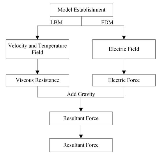
Figure 1.
Flow chart of the calculation procedure.
2.1. Lattice Boltzmann Method
Unlike traditional numerical methods for solving the macroscopic variable equations, LBM is an explicit algorithm that uses the distribution function to describe the macroscopic physical quantities at the mesoscopic scale, based on the dynamic theory. In this paper, the simulation of the internal flow–thermal coupling field process of the oil-immersed transformer is presented by the D2Q9 lattice model with a fully rebound boundary scheme. The directions and weights of the specific migrations are shown in Figure 2.
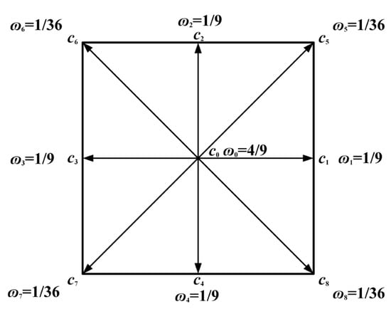
Figure 2.
D2Q9 lattices.
The concrete expression of discrete velocities ci are defined as follows:
where c = Δx/Δt, Δx is the lattice space, and Δt is the lattice time step size.
The natural convection heat transfer process inside the oil-immersed transformer includes two physical fields of flow and heat, which are coupled by buoyancy. The mesoscopic momentum and heat distribution functions fi (x, t) and gi (x, t) can be obtained by solving LBEs.
where ɷf = Δt/τf and ɷg = Δt/τg are the fluid relaxation factor and thermal relaxation factor, respectively; τf and τg are the relaxation times of velocity fields and temperature fields; F is the external force on the particles, which is calculated by the Boussinesq approximation (the internal temperature rise in the transformer is usually less than 40K) [25]:
where ρ is the density, gy is the acceleration of gravity along the y direction, β is the coefficient of thermal expansion, Th and Tc are the temperatures of the solid boundary (hot wall) and the shell (cold wall), and cy is the velocity component along the −y direction.
The calculation formula for the relaxation time of velocity fields and temperature fields are:
where v is kinematic viscosity, α is the thermal diffusion rate, and cs is the lattice sound velocity. For the D2Q9 model in this paper, it is = c2/3.
The equilibrium momentum and heat distribution functions are:
where u is the macroscopic flow rate of the insulating oil fluid.
When LBM is used to solve heat and mass transfer problems, the treatment of boundary conditions is necessary. Remarkably, a uniform heat flux boundary is used here as the heat source. According to Fourier’s Law and the finite difference approximation, the heat flux can be expressed as:
where k is the thermal conductivity of the material.
The density, fluid flow velocity, and temperature of the macroscopic insulating oil can be calculated by the sum of the momentum and heat balance functions along different lattice directions:
2.2. Finite Difference Method for Electric Field
Using the finite difference method to calculate the electromagnetic field can make up for the disadvantages of the analytical method. In the 2D field, according to Poisson’s equation, the potential function φ satisfies the following conditions:
where σ is the bulk charge density and ε is the dielectric constant of a certain point.
In FDM calculations, the region needs to be discretized into grids and nodes, and the partial differential equation is transformed into a different equation by using the difference quotient instead of the derivatives. Thus, the 2D Poisson Equation (12) can be approximately expressed as:
where h is the grid step.
2.3. Calculation of Heat Transfer Parameters
The heat flux density of heat source q and the heat transfer coefficient of the trans-former tank hf are needed in LBM. The heat flux of the heat source is closely related to the loss of windings and the iron core. Moreover, the winding loss is affected by temperature, which is expressed as:
where P0 is the winding loss at temperature T0, k is the temperature coefficient of the conductor, and T is the real-time temperature. Then the heat flux density can be written as:
where qi is the heat flux density of one heating surface, P is the total loss, and Ai is the heat transfer area of one heating surface.
The heat transfer coefficient on different tanks is different, calculated by:
where Nu is the Nusselt number, λ is the thermal conductivity of the medium, and H is the characteristic length. For Nusselt number, according to the empirical formula, its relationship with Prandtl number (Pr) and Rayleigh number (Ra) is as follows:
2.4. Force Calculation of Particles
The Lagrangian motion of particles in oil-immersed transformers is analyzed through a force balance incorporating gravitational, buoyant, viscous drag, and electrostatic interactions. The Stokesian viscous drag force acting on a spherical particle is expressed as:
where m is the mass of the particle, vpf is the relative velocity between particle and fluid, τp is the time constant, ρp is the density of the particle, d is the diameter of the particle, and μ is the viscosity.
Since nanoparticles and metal particles are subjected to different forces in the electric field, they need to be calculated separately. For nanoparticles, the electric field force can be expressed as:
where E is the electric field intensity, and q is the charge on the nanoparticle, which can be calculated by the following formula:
where ε0 and εr are the dielectric constant and relative dielectric constant of vacuum, r is the radius of the particle, and U0 is the Zeta potential of the particle. According to Ma et al. [26], the electric field force on metal particles can be expressed as:
where k is the turbulent kinetic energy, Em is the electric field intensity at the position of the metal particle, ω is the angular frequency, and θ is the phase angle of the sinewave voltage.
where Fg and Fb is gravity and buoyancy, V is the volume of the particle, and ρl is the density of the liquid.
3. Model Parameters and Validity Verification
During the operation of the oil-immersed transformer, the main heat sources come from core and winding loss, and the transformer oil inside the transformer forms a circular flow dominated by natural convection. This study mainly focuses on the qualitative analysis of the influence of nano-modified transformer oil on the heat transfer inside the transformer. Therefore, the computational model only considers core losses and winding losses, while ignoring power losses caused by structural components and eddy currents. The heat transfer process is that the core and winding transferred heat to the surface through conduction, and then the heat is transferred to the tank through the natural convection of the transformer oil. The transformer tank and the air exchange heat through the large-space natural convection and radiation. The model constructed is shown in Figure 3. In this paper, LBM-FDM is applied to solve the problem of heat and mass transfer inside the nano-modified transformer. A 2D axisymmetric thermal-fluid-particle tracking multi-physical field coupling model composed of iron core, primary winding, and secondary winding groups is established. Through simulation, the validity of the results is verified by different methods.
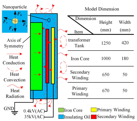
Figure 3.
Two-dimensional model of transformer.
3.1. Model Parameters
In addition to the methods introduced above, the physical parameters and boundary conditions of the simulation need to be introduced. At the same time, because this study is to explore the internal heat transfer characteristics of transformer oil after adding nanoparticles, rather than analyzing the physical properties of nanofluid, we make certain assumptions: nanofluid and transformer oil form a whole, only single-phase flow simulation is considered, and the variability of nanofluid is not considered. When studying its heat transfer process, its heat transfer coefficient is treated as equivalent.
The density of the nanofluid is given as follows [27]:
where subscripts f, nf, and p stand for base fluid, nanofluid, and solid, respectively. ϕ is the solid volume fraction of the nanofluid. The specific heat capacity at constant pressure is described by [28]:
Considering Brownian motion, the dynamic viscosity of the nanofluid can be expressed as [29]:
According to Maxwell [30], the thermal conductivity of the nanofluid can be approximated by:
With the above thermophysical properties, the thermal diffusivity, and Prandtl number of nanofluids can be calculated:
The physical parameters of transformer oil are shown in Table 1 [21].

Table 1.
Thermophysical properties of transformer oil.
The parameters of heat sources, including thermal conductivity kh and winding loss P, are shown in Table 2 [21].

Table 2.
Physical parameters of heat sources.
3.2. Grid Independence Test
In LBM calculation, the number of grids affects the calculation results. In order to obtain accurate results, a grid independence test is needed. The results are shown in Figure 4. As the number of grids increases, the temperature and local Nusselt number will gradually increase and converge, while the computational time and memory occupied will also increase rapidly. Under the above conditions, the 1250 × 420 grid number is selected for the final simulation.
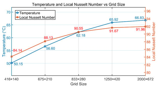
Figure 4.
Grid-dependence test (without nanoparticles).
3.3. Contrast with Thermal Circuit Method
Here, the thermal circuit model applied to calculate the temperature rise in the hot-point in the nano-modified transformer [31] and compared with the results obtained by LBM. In the same initial condition, the results of the two methods, including initial temperature T0, steady-state temperature T1, and temperature rise ΔT, are shown in Table 3.

Table 3.
Comparison of hot-point temperatures between thermal circuit method and lattice Boltzmann method.
As the table shows, the temperature rise calculated by LBM is just a little higher than that calculated by the thermal circuit method, and the relative error is less than 5%. It is concluded that the result obtained using LBM is reliable. As an explicit calculation method, LBM is more predictive and real-time than the hot path method, which relies on empirical formulas.
3.4. Contrast with Finite Volume Method
In order to further verify the validity of the model, the calculation results of LBM and FVM are compared under the same initial conditions. The results are shown in Figure 5 and Figure 6. It can be seen from the figure that the temperature and velocity distribution calculated by FVM are basically consistent with the temperature and velocity distribution calculated by LBM. The temperature near the winding is the highest, the flow velocity is the largest, the top-oil temperature is higher than the bottom-oil temperature, and the hot-spot temperature appears near the high- and low-voltage windings.
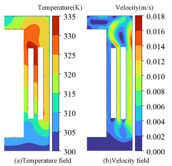
Figure 5.
FVM calculation results.
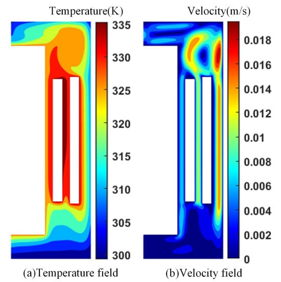
Figure 6.
LBM calculation results.
Comparing the hot-spot temperature calculated by FVM and LBM, the results are shown in Table 4. It can be seen that the calculated temperature rise in LBM is slightly lower than that of FVM, and the relative error is less than 3%. At the same time, we have carried out the local maximum error analysis and found that the maximum error appears below the low-voltage winding, which was 9.45%, further verifying the validity of the model.

Table 4.
Comparison of hot-point temperatures between finite volume method and lattice Boltzmann method.
4. Results and Discussion
4.1. Effect of Nanoparticles on Heat Transfer
The effect of adding nanoparticles on the internal heat transfer characteristics of the oil-immersed transformers can be studied by comparing the Nusselt number. Firstly, an area is selected above the winding, which forms a radiation line from the core to the secondary winding group, with a length of 18 cm. The heat sources are increased to 1.2 and 1.5 times their previous values. The local Nusselt number from the inside to the outside is calculated by increasing the heat source of the transformer to 1.2 times and 1.5 times the original, as shown in Figure 7. The results show that with the increase in heat source, the heat transfer becomes more intense and an evident rise in Nu can be seen.
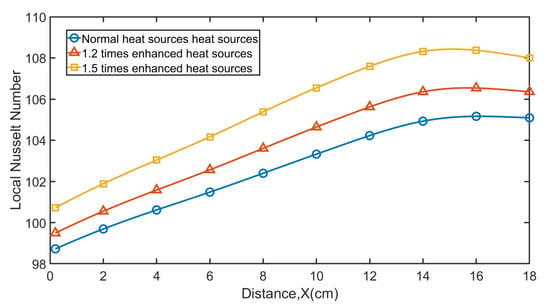
Figure 7.
Comparison of local Nusselt number from the inside out with 1, 1.2, and 1.5 times of normal heat sources.
Next, AIN nanoparticles were added to the transformer, and the local Nusselt numbers at volume fractions of 0, 1%, 5%, and 10% were calculated. The results are shown in Figure 8. With the increase in the volume fraction of AlN nanoparticles, the heat transfer increases slightly and the local Nu number increases. This phenomenon is primarily attributed to the formation of nanofluids, where nanoparticles interact with and bind to liquid molecules, creating a colloidal suspension with enhanced heat transfer properties. Compared to the base fluid, nanofluids exhibit significantly improved thermal conductivity and convective heat transfer efficiency. This is consistent with the results of the literature [32,33]. Lastly, the types of nanoparticles were changed to nano-silica (SiO2) and alumina (Al2O3), and the results were compared with those obtained using AlN nanoparticles. The result is shown in Figure 9, and it can be seen that the Nu of AlN and Al2O3 is similar and slightly higher than that of SiO2. This means that AlN and Al2O3 nanoparticles have a better ability to suppress the temperature rise in transformer oil compared to SiO2 nanoparticles.
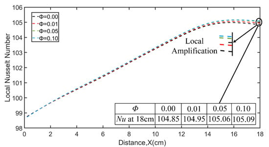
Figure 8.
Comparison of local Nusselt number from the inside out with volume fraction of 0, 0.01, 0.05, and 0.1.
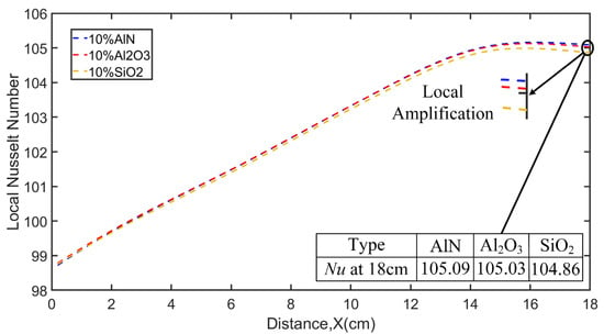
Figure 9.
Comparison of local Nusselt number from the inside out with particle components of Al2O3, AlN, and SiO2.
4.2. Transfer of Nanoparticles
In order to simplify the calculation of the electric field force, we used FDM to calculate the electric field distribution when the primary winding voltage reaches the peak, as shown in Figure 10. It can be seen that the electric field is mainly distributed around the primary winding. The electric field force on the particles at other times is calculated by the Formula (25).
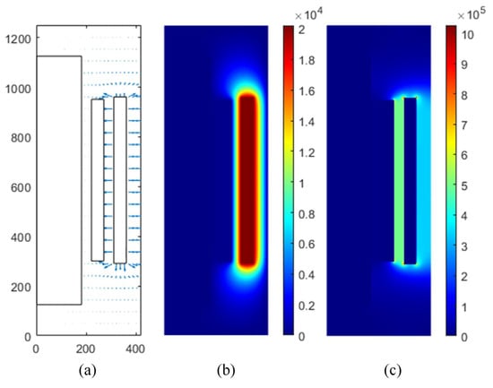
Figure 10.
(a) Electric field vector diagram, (b)the potential cloud diagram, and (c) the electric field cloud diagram.
Two nanoparticles at different positions were set as research objects. The trajectories of the nanoparticles under the force at 300 s, 600 s, 900 s, 1200 s, and 1500 s are shown in Figure 11. The blue line represents the trajectory, and the red circle represents the initial position of a particle. As shown in the figure, the nanoparticles at two different positions follow the flow of transformer oil and move periodically in the form of natural convection in the clockwise direction. This is because the radius of nanoparticles is small, and the viscous resistance is much larger than the electric field force and gravity, indicating that nanoparticles are mainly affected by the force of viscous resistance.
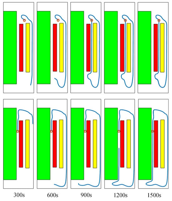
Figure 11.
Movement tracks of nanoparticles.
4.3. The Transfer of Metal Particles
Similarly, the research objects were replaced with three metal particles located at different positions, and their trajectories at 1500 s are shown in Figure 12.
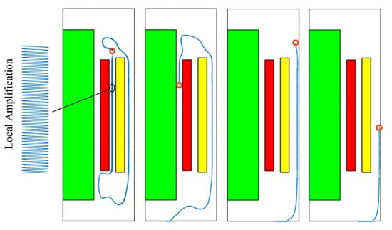
Figure 12.
Movement tracks of metal particles.
The trajectories of metal particles and nanoparticles exhibit distinct differences, particularly in regions of elevated electric field strength and low oil flow velocity (Figure 12). The interaction between particles and flow field is mainly manifested as follows: the flow of transformer oil acts on the particles through oil flow resistance, and the particles affect the flow field through reaction force. Under high-speed flow conditions, both particle types flow with the transformer oil due to the dominance of viscous resistance. However, in low-velocity regions, gravitational sedimentation becomes significant for metal particles, attributable to their substantially higher mass density compared to nanoparticles. If too many particles are deposited at the bottom of the transformer, partial discharge and thermal accumulation may occur, thus affecting the stable operation of the transformer. In addition, when the particles are close to the winding, the effect of the electric field force is more obvious. Under the action of the power frequency alternating sinusoidal electric field, the trajectories of the particles have obvious periodic oscillation (dense tracks in Figure 12), which is consistent with the results of the literature [15,16].
5. Conclusions
In this study, a simulation model of the nano-modified oil-immersed transformer was constructed based on LBM, and the heat and mass transfer characteristics of nano-modified transformer oil were calculated. Compared with the calculation results of the same model by the thermal circuit method and the finite volume method, the results showed that the error is within 5%, which verifies the validity of the model.
- (1)
- As the particle volume fraction in the nano-modified oil-immersed transformer increases, the local Nusselt number rises, indicating enhanced convective heat transfer performance. The migration behavior of particles varies by type: nanoparticles follow the natural convection direction of the transformer oil. Metal particles are advected by oil flow in high-speed region but show gravitational settling and oscillation in the low-speed region, and because metal particles can carry electric charge, this may produce partial discharge phenomena, thus endangering the safe operation of the transformer.
- (2)
- The LBM is applied to model heat and mass transfer in nanoparticle-enhanced oil-immersed transformers, offering an explicit computational framework for thermal–fluid simulations. Relative to the FVM, LBM demonstrates superior computational efficiency and reduced memory requirements in transient thermal analysis, owing to its inherent parallel computing capabilities.
- (3)
- Limited by the constraint of the two-dimensional model constructed in this paper, the influence of the three-dimensional effect of transformer oil flow is not considered in the simulation. In the future, a three-dimensional simulation model of transformer will be constructed based on the proposed method to further study the heat transfer characteristics, including the axial heat transfer process and the motion characteristics, including multiple particles.
Author Contributions
Conceptualization, W.Y.; methodology, W.Y. and L.X.; software, X.G.; validation, W.Y.; formal analysis, W.Y.; investigation, X.G. and L.X.; resources, X.G.; data curation, X.G.; writing—original draft preparation, W.Y.; writing—review and editing, X.G. and L.X.; visualization, W.Y.; supervision, X.G.; project administration, X.G.; funding acquisition, X.G. and L.X. All authors have read and agreed to the published version of the manuscript.
Funding
This research received no external funding.
Data Availability Statement
The original contributions presented in this study are included in the article. Further inquiries can be directed to the corresponding author.
Conflicts of Interest
The authors declare no conflicts of interest.
References
- Choi, S.U.S.; Eastman, J.A. Enhancing Thermal Conductivity of Fluids with Nanoparticles; Argonne National Lab: Argonne, IL, USA, 1995; pp. 1–8. [Google Scholar]
- Miadzvedzeva, M.; Fedotov, A.S.; Zur, I.; Fedotova, J. Heat Transfer and Flow Dynamics for Natural Convection in Fe3O4/H2O Nanofluid. Energies 2025, 18, 2767. [Google Scholar] [CrossRef]
- Li, F.; Tan, Z.; He, H.; Zhou, Y.; Tang, X.; Zhu, W. Research on Thermal Performance of the Microchannel with Internal Cavities under Al2O3-Water Nanofluid. Energies 2025, 18, 4419. [Google Scholar] [CrossRef]
- Kadim, E.J.; Noorden, Z.A.; Adzis, Z.; Azis, N. Nanoparticle Effects on the Electrical and Thermal Performance of the Transformer Mineral Oil. IEEE Trans. Dielectr. Electr. Insul. 2023, 30, 1932–1940. [Google Scholar] [CrossRef]
- Seddik, M.S.; Shazly, J.; Eteiba, M.B. Thermal Analysis of Power Transformer Using 2D and 3D Finite Element Method. Energies 2024, 17, 3203. [Google Scholar] [CrossRef]
- Ai, M.; Shan, Y. The Whole Field Temperature Rise Calculation of Oil-Immersed Power Transformer Based on Thermal Network Method. Int. J. Appl. Electromagn. Mech. 2022, 70, 55–72. [Google Scholar] [CrossRef]
- Wang, S.; Li, X.; Zhang, R.; Sha, Z.; Wu, Z.; Zhang, Q. Thermal Distribution Characteristics Related to the Transformer Fine Structure Predicted by CFD-Based Spline Interpolation. IEEE Trans. Dielectr. Electr. Insul. 2023, 30, 892–901. [Google Scholar] [CrossRef]
- Abdali, A.; Maosumkhani, H.; Mazlumi, K.; Rabiee, A. Accurate and Nonuniform CFD-Based Thermal Behavior Analysis of Distribution Transformers: Voltage Imbalance Effect. J. Braz. Soc. Mech. Sci. Eng. 2023, 45, 613. [Google Scholar] [CrossRef]
- Smolyanov, I.; Shmakov, E.; Butusov, D.; Khalyasmaa, A.I. Review of Modeling Approaches for Conjugate Heat Transfer Processes in Oil-Immersed Transformers. Computation 2024, 12, 97. [Google Scholar] [CrossRef]
- Xiao, J.; Zhang, Z.; Hao, Y.; Zhao, H.; Liu, X. Method for Measuring Thermal Flow Field Distribution in Oil-Immersed Transformer Using Dynamic Heat Transfer Coefficient. IEEE Trans. Instrum. Meas. 2024, 73, 1–11. [Google Scholar] [CrossRef]
- Sun, Z.; Yao, Q.; Jin, H.; Xu, Y.; Hang, W.; Chen, H.; Li, K.; Shi, L.; Gu, J.; Zhang, Q.; et al. A Novel In-Situ Sensor Calibration Method for Building Thermal Systems Based on Virtual Samples and Autoencoder. Energy 2024, 297, 131314. [Google Scholar] [CrossRef]
- Zhang, F.; Nghiem, L.; Chen, Z. A Novel Approach to Solve Hyperbolic Buckley-Leverett Equation by Using a Transformer Based Physics Informed Neural Network. Geoenergy Sci. Eng. 2024, 236, 212711. [Google Scholar] [CrossRef]
- Tang, P.; Zhang, Z.; Tong, J.; Long, T.; Huang, C.; Qi, Z. Predicting Transformer Temperature Field Based on Physics-informed Neural Networks. High Volt. 2024, 9, 839–852. [Google Scholar] [CrossRef]
- Wang, F.; Liang, K.; Zhong, L.; Chen, S.; Wan, T.; Duan, X.; Dong, X. Effect of Metal Ions and Suspended Particles on Streamer Propagation. IEEE Trans. Dielectr. Electr. Insul. 2023, 30, 1154–1161. [Google Scholar] [CrossRef]
- Wei, B.; Wang, Z.; Qi, R.; Wang, X.; Zhao, T. A Study on the Motion Behavior of Metallic Contaminant Particles in Transformer Insulation Oil under Multiphysical Fields. Sensors 2024, 24, 5483. [Google Scholar] [CrossRef]
- Li, X.; Wang, Y.; Yan, C.; Bi, J.; Wang, F. Motion Characteristic of Copper Particle in Insulating Oil under AC and DC Voltages. In Proceedings of the 2017 IEEE 19th International Conference on Dielectric Liquids (ICDL), Manchester, UK, 25–29 June 2017; IEEE: New York, NY, USA, 2017; pp. 1–4. [Google Scholar]
- Yu, W.; Guan, X.; Lai, Z.; Mo, D.; Shu, S. MRT-LBM-EnKF Simulation of Transient Temperature Rise of Three-phase Enclosure GIS Bus Considering Non-uniform Heat Transfer Boundary of Shell. In Proceedings of the CSEE, Nanjing, China, 21–23 February 2025; Available online: https://kns.cnki.net/KCMS/detail/detail.aspx?dbcode=CAPJ&dbname=CAPJLAST&filename=ZGDC20250512002&uniplatform=OVERSEA&v=8Axxp8z74077MtDkC7DB-_TZ9Dkq5ac_qEWjDVVot_uqiHAvGuixy9_ciZYWLV9W (accessed on 22 September 2025). (In Chinese).
- Hong, N.; Liu, X.; Wang, H. A Conservative Phase-Field Lattice Boltzmann Method for Incompressible Two-Phase Flows. Int. J. Numer. Methods Fluids 2023, 95, 1431–1440. [Google Scholar] [CrossRef]
- Yuan, Z.; Dong, Y.; Jin, Z. Numerical Simulation of MHD Natural Convection and Entropy Generation in Semicircular Cavity Based on LBM. Energies 2023, 16, 4055. [Google Scholar] [CrossRef]
- Lin, Q.; Li, Q.; Xu, P.; Zheng, R.; Bao, J.; Li, L.; Tan, D. Transport Mechanism and Optimization Design of LBM–LES Coupling-Based Two-Phase Flow in Static Mixers. Processes 2025, 13, 1666. [Google Scholar] [CrossRef]
- Yu, W.; Guan, X.; Zhao, J.; Tu, J.; Lai, Z. Transient Temperature Rise Simulation and Load Capacity Eval-uation of Oil-Immersed Transformer Based on Lattice Boltzmann Method. Trans. China Electrotech. Soc. 2025, 40, 3315–3325. (In Chinese) [Google Scholar] [CrossRef]
- Karki, P.; Gangawane, K. Study of Magnetohydrodynamics-Based-Mixed Convection & Entropy Generation within the Rectangular Enclosure with Two Obstacles for Cu-SiO2 Multiwalled Carbon Nanotubes Ternary Hybrid Nanofluids. Numer. Heat Transf. Part A Appl. 2024, 85, 2257–2279. [Google Scholar] [CrossRef]
- Nemati, M.; Sefid, M. Correction: Magnetohydrodynamics Combined Convection Modeling via LBM for Shear Thinning Nanofluids within an Inclined Enclosure: Appraisement of Heat Transfer and Entropy under the Impact of Various Parameters. Comput. Part. Mech. 2024, 11, 509. [Google Scholar] [CrossRef]
- Oulahou, Y.; Elguennouni, Y.; Hssikou, M.; Baliti, J.; Alaoui, M. Theoretical Examination of the Volume Concentration and Nanoparticles Density Influence on the Convective Heat Transfer Enhancement of Nanofluid in 2D Cavity Including the Square Heater. Probl. Reg. Energ. 2023, 4, 55–70. [Google Scholar] [CrossRef]
- Mohamad, A.A. Lattice Boltzmann Method: Fundamentals and Engineering Applications with Computer Codes, 2011th ed.; Springer: London, UK, 2014; ISBN 978-1-4471-6099-1. [Google Scholar]
- Ma, S.; Tang, J.; Zhang, M.; Liu, Z.; Li, X. Simulation Study on Distribution and Influence Factors of Metal Particles in Traction Transformer. High Volt. Eng. 2015, 41, 3628–3634. [Google Scholar] [CrossRef]
- Brinkman, H.C. The Viscosity of Concentrated Suspensions and Solutions. J. Chem. Phys. 1952, 20, 571. [Google Scholar] [CrossRef]
- Khanafer, K.; Vafai, K.; Lightstone, M. Buoyancy-Driven Heat Transfer Enhancement in a Two-Dimensional Enclosure Utilizing Nanofluids. Int. J. Heat Mass Transf. 2003, 46, 3639–3653. [Google Scholar] [CrossRef]
- Nguyen, C.T.; Desgranges, F.; Galanis, N.; Roy, G.; Maré, T.; Boucher, S.; Angue Mintsa, H. Viscosity Data for Al2O3–Water Nanofluid—Hysteresis: Is Heat Transfer Enhancement Using Nanofluids Reliable? Int. J. Therm. Sci. 2008, 47, 103–111. [Google Scholar] [CrossRef]
- Clerk-Maxwell, J. A Treatise on Electricity and Magnetism. Nature 1873, 7, 478–480. [Google Scholar] [CrossRef]
- Swift, G.; Molinski, T.S.; Lehn, W. A Fundamental Approach to Transformer Thermal Modeling. I. Theory and Equivalent Circuit. IEEE Trans. Power Deliv. 2001, 16, 171–175. [Google Scholar] [CrossRef]
- Pourpasha, H.; Zeinali Heris, S.; Mousavi, S.B. Thermal Performance of Novel ZnFe2O4 and TiO2-Doped MWCNT Nanocomposites in Transformer Oil. J. Mol. Liq. 2024, 394, 123727. [Google Scholar] [CrossRef]
- Yang, P.; Peng, Y.; Ramachandran, D.S.; Alkaabi, A.K.; Wu, J. Numerical Analysis of Electrothermoconvection of a Dielectric Nanofluid in a Heated Cavity. Phys. Scr. 2024, 99, 065034. [Google Scholar] [CrossRef]
Disclaimer/Publisher’s Note: The statements, opinions and data contained in all publications are solely those of the individual author(s) and contributor(s) and not of MDPI and/or the editor(s). MDPI and/or the editor(s) disclaim responsibility for any injury to people or property resulting from any ideas, methods, instructions or products referred to in the content. |
© 2025 by the authors. Licensee MDPI, Basel, Switzerland. This article is an open access article distributed under the terms and conditions of the Creative Commons Attribution (CC BY) license (https://creativecommons.org/licenses/by/4.0/).