1. Introduction
Transitioning toward renewable resources from fossil-fuel-based energy systems is indispensable for reducing greenhouse emissions. Such sustainable sources are primarily integrated into the traditional power grids through power-electronic converters. In particular, voltage-source converters (VSCs) are commonly utilized in industrial applications [
1], wind and solar energy generation [
2,
3], HVDC systems [
4,
5], electric vehicle motor drives, etc.
Computer studies and analyses of power-electronic converter-based systems typically require conducting numerous electromagnetic transient (EMT) simulations, either offline or in real-time [
6,
7]. In such studies, it is generally desirable to use large time-step sizes [
7], as large as to capture the system dynamics (dependent on its time constants) accurately [
8], so that the simulations can run quickly. More efficient EMT simulations enable studies of larger-scale and more practical power systems executed on given computational hardware. Indeed, modern computing machines have high processing power. However, due to their finite processing speed, memory, I/O bandwidth, etc., using large time step sizes is critically important in simulations of large power systems. This becomes even more critical in real-time simulations where all the computations must be completed within the simulation time-step window.
Various techniques can be applied to facilitate the simulations of large power systems with many power-electronic converters. An aggregation of converter system models to reduce the network size for EMT simulations is a well-known method [
9,
10,
11]. It is also commonly accepted to use computationally efficient average-value models (AVMs) of the converters instead of their time-consuming detailed switching models [
12] in system-level studies where the overall dynamic behavior of the whole converter is of particular interest rather than the details of the individual switches. The AVMs discard the high-frequency switching events and are typically much faster than the switching models, which require small simulation steps and/or interpolation techniques to handle each switching moment [
13].
Various AVMs have been developed for different converters and applications [
14,
15,
16,
17,
18,
19,
20,
21,
22,
23,
24,
25,
26]. Despite their numerical advantages compared to the switching models, the interfacing of AVMs using conventional methods [
27] can become problematic for simulations with large time step sizes in nodal-based EMT programs that employ non-iterative methods for network solution, e.g., the PSCAD software.
Specifically, the AVMs are conventionally implemented using dependent voltage/current sources that relate the average values of the dc terminal variables to the fundamental frequency components of the ac terminal variables of the converter. This type of interfacing requires a time-step delay (relaxation) for the controlled sources. The effect of this delay can become significant and deteriorate the solution’s numerical accuracy when large time steps are used [
28]. Although some tools, such as the modified augmented nodal analysis (MANA) [
29], can remove the interfacing delay by iterating on a solution at a current step, these iterative methods increase the computational burden per time step. Additionally, non-iterative methods are preferred for real-time simulations due to constraints on the computational burden per step, as seen in the nodal-based RTDS real-time simulator [
30].
One solution to avoid the interfacing time-step delay without iterative methods is to combine the VSC’s state-space model and the network’s nodal equations based on the so-called state-space nodal (SSN) approach [
31]. A state-space AVM (SS-AVM) was developed in [
32] for VSCs, which assumes a series
RL filter at the ac terminals and a capacitor at the dc terminal, all within the considered model. A direct interfacing method (DI-AVM) was presented in [
33,
34,
35], which enables connection to an arbitrary network without restrictions on the configuration within the model. Effectively, the SS-AVM and DI-AVM formulate the converter within the nodal framework itself and incorporate the converter’s equations as part of the nodal conductance matrix, whose governing equations are solved simultaneously with the rest of the system. However, the SS-AVM and DI-AVM have variable conductance matrices, which need to be recalculated at every time step. To reduce the computations, a constant-parameter DI-AVM (CP-DI-AVM) was also presented in [
32]. In the CP-DI-AVM, the equivalent conductance matrix of the converter is held constant, and any variations are captured via equivalent history sources. Although this approach is well-suited when the solver cost of updating the network matrices at every step is a concern (e.g., in real-time simulations), it trades accuracy for computational speed.
Additionally, the so-called discretized impedance (or admittance)-based modeling (DIBM or DABM) has been developed [
36,
37], which replaces the entire converter subsystem (including filters, controllers, etc.) with equivalent impedances (or admittances). This is performed by formulating the converter subsystem in the Laplace domain and then discretizing the state equations as an equivalent conductance with history voltage (or current) sources. This reduces the number of active states and the size of the nodal equations, allowing for a simultaneous network solution without artificial interfacing delay. Such DIBMs/DABMs can also be especially useful for the stability analysis of inverter-based resources (IBRs) [
38,
39]. However, their formulations result in burying the entire converter submodules (circuit, filters, controllers, etc.) inside the collapsed equivalent model, which does not offer the desirable plug-and-play modeling capability because it will only be valid for that particular system configuration and controller type.
In this paper, an alternative SS-AVM is developed that does not require a dc capacitor inside the model; therefore, the dc-side subsystem can have an arbitrary composition. A DI-AVM is also proposed, assuming series resistances (of the filter and/or lines/cables) are included within the model. This new model is numerically more robust compared to the one in [
33,
34,
35]. A CP-DI-AVM is also proposed, which is realized as a combination of a constant conductance matrix and dependent sources, as opposed to the one in [
32], which is realized using controlled sources only.
The performance of the proposed interfacing methods of AVMs is verified in EMT simulations of a VSC-based ac–dc system using PSCAD software. It is shown that the proposed methods offer numerically efficient solutions while being stable even with large time-step sizes.
It should be noted that the focus of this study is developing new interfacing techniques for AVMs of VSCs that can handle larger time-step sizes in simulations. For this purpose, the detailed switching model of the VSCs (already validated in the literature) has been used as the base/reference, and the results of the AVMs are compared to that in terms of consistency and accuracy. The high accuracy of the proposed models compared to the detailed switching models of the VSCs confirms that they can be valuable assets for efficient simulations of these systems.
The rest of this article is organized as follows: In
Section 2, various interfacing techniques of the VSC AVMs are presented, including the traditional IDI-AVM in
Section 2.1, the proposed SS-AVM in
Section 2.2, the proposed DI-AVM in
Section 2.3, and the proposed CP-DI-AVM in
Section 2.4. The performance of the subject interfacing techniques is investigated in
Section 3 in terms of numerical accuracy and computational speed.
Section 4 summarizes the conclusions drawn based on the presented studies.
2. Average-Value Modeling of VSCs
Without loss of generality, a generic ac–dc system, as shown in
Figure 1, is considered to illustrate the modeling techniques. Therein, a VSC is connected to the point of synchronization (POS) through a filter represented by an
RL branch. The series
RL may also represent the impedance of the connecting lines or cables. The controllers receive measurements from the system (i.e., the dc terminal voltage
, the ac terminal currents
, and the voltages at the POS
) and compute the quantities required by the switching pulse generator to establish the voltages at the ac terminal of the converter (i.e.,
) that track the desired references.
It is assumed that the POS voltages are sinusoidal and can be represented as
where
E is the amplitude of the phase voltages, and
is the angle of the POS phase
a voltage, with
being the frequency of the ac grid. Based on the dc link voltage
, the VSC establishes the ac voltages
, which can be expressed using their Fourier series as
where the superscript 1 denotes the fundamental frequency, and
n denotes the
nth-order harmonic. Specifically, the fundamental frequency components of the ac voltages are related to the average value of the dc-side voltage as
Here,
is the vector of the modulation indices for the three phases, which can be expressed as
In (4), the coefficient
determines the magnitude of the ac terminal voltages and depends on the switching strategy [
32,
40,
41], as follows:
where
M is the modulation index (0 <
M < 1). Also,
is the so-called power angle, which can be regulated to control the power flow between the ac and dc systems and is defined as the angle shift between the POS voltages
and the fundamental frequency components of the ac terminal voltages
as
An expression similar to (2) can also be written for the ac currents. A phasor diagram of the ac voltages and currents for the system shown in
Figure 1 is depicted in
Figure 2, demonstrating the phase shifts between the quantities.
The dc-side variables can also be expressed as the sum of their average values and oscillatory components (i.e., switching ripples), as
In (7), the symbol tilde (~) denotes the ripples, and the bar symbol denotes the average value of the variables, which can be computed as
where
is the switching period.
In the AVMs, the switching ripples in the ac and dc terminal variables are ignored because they are less significant and also have zero average values; and their fundamental frequency components (i.e., and ) and average values (i.e., and ) are captured, respectively.
The interfacing methods presented in the subsequent subsections use different expressions to relate these fundamental frequency ac and averaged dc variables. From here on, superscript 1 for the fundamental frequency components of the ac variables and the bar symbol at the top of the averaged dc variables are dropped for simplicity of notations.
2.1. Conventional Indirectly Interfaced AVM
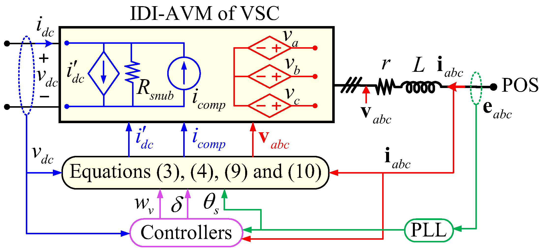
In the so-called conventional indirectly interfaced AVMs (IDI-AVMs) of VSCs (see subsection II-A of [
32]), the controlled voltage and current sources are used to interface with the ac and dc subsystems, respectively, as illustrated in
Figure 3.
The values of the ac voltages are computed using (3) and (4) from the dc voltage, while the values of
and
are calculated by the controllers. The value of the controlled current source, denoted by
in
Figure 3, is computed based on the input/output power balance, assuming a lossless converter (i.e.,
), as
To enhance the numerical stability of the IDI-AVM, a fictitious snubber resistor
may be added to the dc terminal [
27], as shown in
Figure 3. To eliminate the steady-state error in the dc terminal current due to the fictitious snubber, a compensating current source can be used that may be calculated as follows:
The computation in (10) is based on the value of the dc voltage from the preceding simulation time step , which is already available. However, for computations in (3) and (9), the values of and are not yet available at the current time step because they must be calculated as part of the network solution. Therefore, (non-iterative) nodal-based programs use their values calculated at the previous step [i.e., in (3) and in (9)] inevitably. This time-step delay (relaxation) for the controlled sources at the interface (hence the name indirectly interfaced AVM) can cause numerical inaccuracy and/or instability, especially at large simulation time-step sizes . This is because, with a large , the error introduced by using instead of the actual and instead of the actual , will be significant, especially for the ac variables and also during the transients.
2.2. Proposed State-Space AVM
The time-step delay associated with the IDI-AVMs can be avoided by formulating the state-space AVM (SS-AVM) equations of the system in
Figure 1 in the nodal form. Specifically, the dynamics of the ac system is expressed based on the KVL (Kirchhoff’s Voltage Law) in
Figure 1 and using (3) as
To achieve a nodal form, the differential equations (11) are discretized using a specific integration rule. Here, for consistency with most nodal EMT simulators, the trapezoidal method is adopted for the discretization, where discretizing the differential equation
dg/dt = f with a time step
results in a difference equation expressed as
Applying (12) to (11) and combining with (9), the system variables can be written in the nodal form as
where the superscript “ss” denotes state space, and the vectors
,
, and
are defined as
Equation (13) includes the voltages at the POS and dc terminal, the ac and dc currents, and the history terms of the currents (which are available from the previous time step), respectively. Also,
is the equivalent conductance matrix of the SS-AVM of the VSC, which is yielded to be as follows:
where
, with
being the equivalent resistance of the discretized ac-side inductor. The history currents can be expressed as
where
.
Based on (13), the proposed SS-AVM of VSCs can be implemented as shown in
Figure 4. Therein, the conductance matrix
is realized based on (4) and (15) using coupled resistors (shown in red), and the history terms
are injected as current sources (shown in blue) based on (4) and (16).
It should be noted that the ac-side series
RL impedance has become part of the model in the SS-AVM, and the ac-side of the VSC is interfaced with the POS, as illustrated in
Figure 4. In the meantime, the current sources inside the model are formulated based on the terminal variables from the previous time step [see (16)] and can be calculated at the current time step without delay.
2.3. Proposed Directly Interfaced AVM
In the proposed directly interfaced AVM (DI-AVM), the line resistance is included inside the model, and the ac-side equations are written based on the voltages
in
Figure 1 and using (3) as
After manipulating (17) and combining with (9), the system variables can be written in the nodal form as
where the superscript “DI” denotes “directly interfaced.” The vectors
and
are defined as
which include the voltages at the nodes in the middle of the series
RL impedance and the dc terminal, as well as the ac and dc currents, respectively. Also,
is the equivalent conductance matrix of the DI-AVM of the VSC expressed as
Based on (18), the proposed DI-AVM of VSCs can be implemented as shown in
Figure 5. Therein, only a conductance matrix
is needed, which is realized based on (4) and (20). It is also possible to implement
using variable resistors, as shown in
Figure 6, where the values of the resistors are calculated
As seen in (18), the proposed DI-AVM is modeled as a pure conductance matrix and does not require any source injections. The conductance matrix in (20) or the variable resistors in (21) are also merged into the overall system conductance matrix for the network solution. Therefore, no time-step delay is involved.
2.4. Proposed Constant-Parameter Directly Interfaced AVM
As deduced from (15) and (20), the conductance matrices in both the SS-AVM and the DI-AVM are variable (i.e., they are functions of the time-varying modulation indices ) and need to be recalculated at every time step during the simulation. This requires extra computations per step and can result in long simulations, especially when the number of nodes in the system (i.e., the size of the overall network conductance matrix) is large.
In the proposed CP-DI-AVM, the terms in (18) associated with the variable terms in the conductance matrix are approximated from the previous time steps, retaining only the constant part of the matrix, and (18) is rewritten as follows:
where
and
are chosen the same as
and
in (16), respectively. Also,
includes only the constant terms of
in (20) and is expressed as
The history current terms in (22) include the variable terms in (18) approximated using their values from the preceding simulation time steps and are calculated as follows:
with
and
The variables with superscript ^ are the estimated values based on their solution from two previous time steps, using a linear approximation as
with
x representing the subject variable.
Based on (22), the proposed CP-DI-AVM of VSCs can be implemented as shown in
Figure 7. Therein, the constant conductance matrix
is realized based on (23) using three constant resistors (shown in red with values equal to
r), and the history terms
are injected as current sources (shown in blue) based on (24)–(27).
3. Performance in EMT Simulations
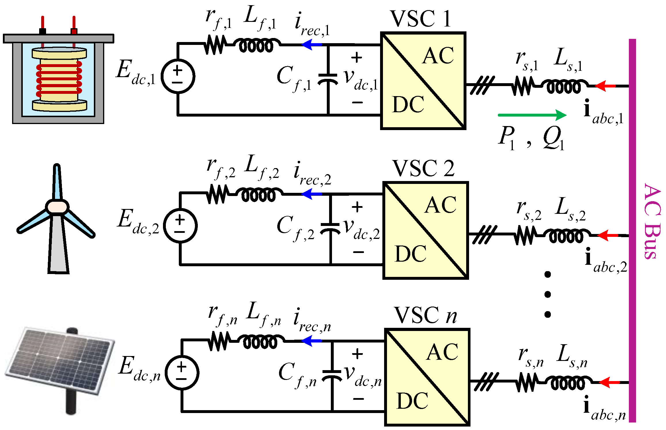
Here, the performance and numerical properties of the four subject AVMs (i.e., conventional IDI-AVM, proposed SS-AVM, proposed DI-AVM, and proposed CP-DI-AVM) are investigated for EMT simulations of the case study system shown in
Figure 8. Specifically, the performance of the AVMs is investigated when run with small and large time-step sizes. The system comprises multiple ac–dc VSCs and can represent energy conversion based on renewable resources, including wind and solar power, as well as storage systems. Therefore, the operation of the VSCs in both rectification and inversion modes (i.e., absorbing and supplying power) is considered. The system in
Figure 8 is implemented in PSCAD V5.0.2 with the four AVMs of VSCs according to the descriptions in
Section 2. To verify the AVMs, the detailed switching models of VSCs are also implemented, adopting the sinusoidal pulse-width modulation (SPWM) with a switching frequency of 2340 Hz (corresponding to an odd triple frequency modulation ratio of 39, given the 60 Hz ac system, to minimize the harmonics [
40]). The system parameters are summarized in
Appendix A, where it is assumed that the dc and ac filter impedances are similar for all VSCs, for simplicity.
The detailed switching model is simulated with a small time-step size of to ensure adequate accuracy and resolution in capturing the discrete switching details. The DI-AVM run with a small time-step size is considered the reference AVM because its solution does not require time-step delays and/or fictitious snubbers that introduce errors. The value of snubber resistance for the IDI-AVM is selected as to provide sufficient damping while not introducing much error during transients.
3.1. Numerical Accuracy
Focusing on one ac–dc setup in
Figure 8, e.g., VSC1, it is assumed that the system initially operates in a steady state, transferring ~10.7 kW from the dc source to the ac grid (discharge mode of the energy storage). This corresponds to having the converter modulation index and angle shift as
and
, respectively. Then, at
, the converter command is switched to charging mode to transfer ~9 kW from the ac grid to the dc energy storage. This is achieved by changing the rectified dc current (
in
Figure 8) from −17.8 A to +15.1 through stepping the angle shift to
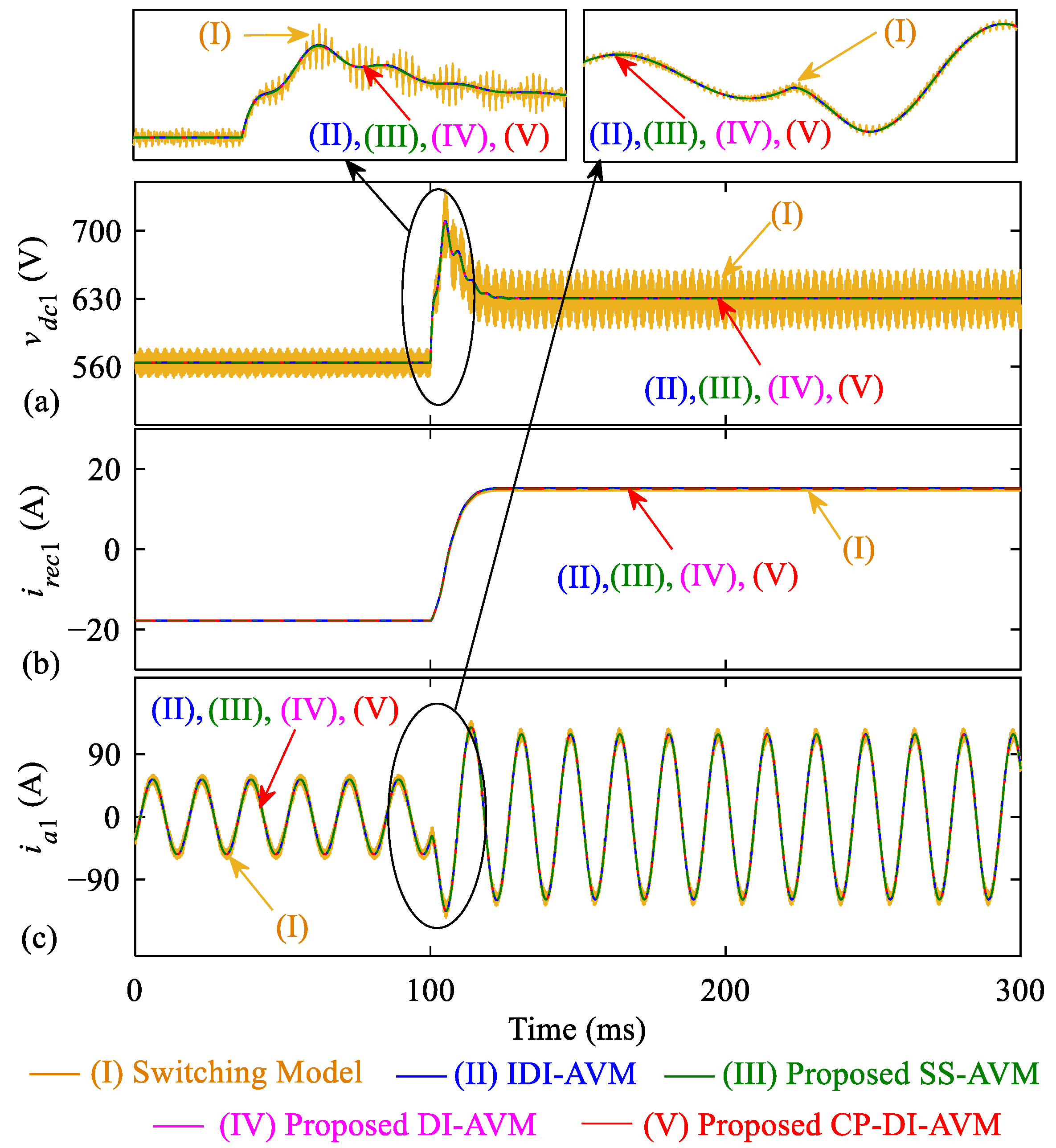
. The transient response of VSC1 terminal variables obtained by the detailed switching model, as well as the AVMs run with a small time-step size of
are shown in
Figure 9.
As seen in
Figure 9, when run with small time steps, all four subject AVMs can provide accurate results where the (lower frequency) dynamics during transients are captured consistently with the detailed switching model (if switching ripples are neglected).
The same simulation study is repeated when the AVMs are run with a large time-step size of
, and the results are demonstrated in
Figure 10. As seen, the IDI-AVM clearly predicts incorrect results (e.g., as in
Figure 10b for the ac current) with sustained numerical oscillations (as seen in
Figure 10a for the rectified dc voltage). This also indicates that the IDI-AVM solution is very close to numerical instability, and the results become entirely numerically unstable at
. Whereas, the three proposed AVMs (i.e., SS-AVM, DI-AVM, and CP-DI-AVM) reconstruct the dc and ac waveforms accurately at such a large time-step size of
, compared to the reference solution obtained with
. Nevertheless, as seen in the magnified view of
Figure 10a, the proposed CP-DI-AVM also exhibits subtle deviations from the reference solution, which are due to the approximations used in (24)–(27). Therefore, one should consider a maximum allowed step size for achieving the desired accuracy.
To confirm the numerical instability of the IDI-AVM at Δ
t = 150 µs, the results of the AVMs obtained with a simulation time-step size of Δ
t = 150 µs are shown in
Figure 11. As observed, the values of the results obtained by the IDI-AVM increase unboundedly, indicating an unstable solution [note the numeric values of the vertical axes]. In the meantime, the proposed AVMs provide accurate results compared to the reference AVM solution, as shown in the magnified parts of the subplots in
Figure 11.
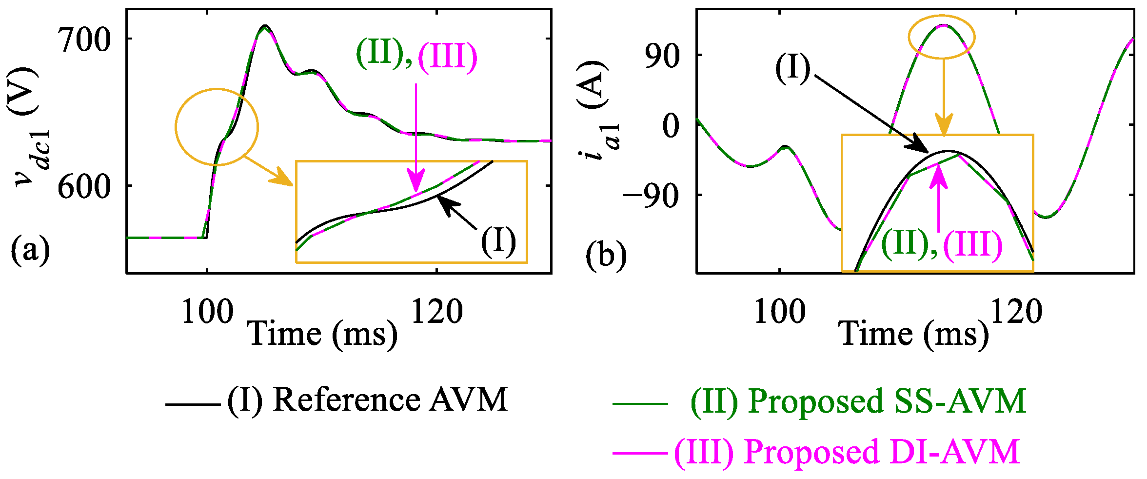
To demonstrate the performance of the two proposed SS-AVM and DI-AVM (which do not employ the time-step delay and/or approximations) for simulations with very large time-step sizes, the response of the dc voltage and ac current of VSC1 at the moment of transient obtained with these two models at
are shown in
Figure 12.
As shown in
Figure 12, both SS-AVM and DI-AVM yield consistent results, demonstrating their high accuracy and reliability compared to the reference solution. It was verified that the time-step size could be increased up to ~1 ms. However, it should also be noted that, unlike the CP-DI-AVM, which has a constant conductance matrix, the
G matrices in the SS-AVM and DI-AVM are time-varying and must be recalculated at each time step of the simulation, which may be a limiting factor in terms of computational efficiency.
3.2. Numerical Accuracy Under Faults
Here, the performance of the proposed models is verified under a fault condition. It is assumed that the system in
Figure 8 operates in a steady-state condition following the events described in
Section 3.1. Then, it is assumed that at
t = 300 ms, a three-phase-to-ground fault [with fault resistance of 50 mΩ] occurs at the ac side of VSC1. For this purpose, the ac impedance is split into two parts (half representing the line impedance and half representing the filter), and the fault is applied in the middle. The dc link voltage and ac current (phase
a) are shown in
Figure 13 as captured by the detailed switching model (run with Δ
t = 2 µs), the traditional IDI-AVM, the proposed SS-AVM, DI-AVM, and CP-DI-AVM (all run with Δ
t = 50 µs).
As can be observed from
Figure 13, the fault results in a drop in the dc voltage and an increase in the current. In the meantime, it is observed that the traditional IDI-AVM obtains inaccurate results compared to the detailed switching model, especially during the transient. Whereas, the three proposed models (SS-AVM, DI-AVM, and CP-DI-AVM) are able to provide very accurate results compared to the switching model under the faulty condition in the system.
The results obtained by the proposed SS-AVM and DI-AVM obtained with a large simulation time-step size of Δ
t = 300 µs are also shown in
Figure 14, compared with the reference AVM solution obtained with Δ
t = 10 µs. As observed in
Figure 14, the proposed models are also able to predict very accurate results even at such large time-step sizes.
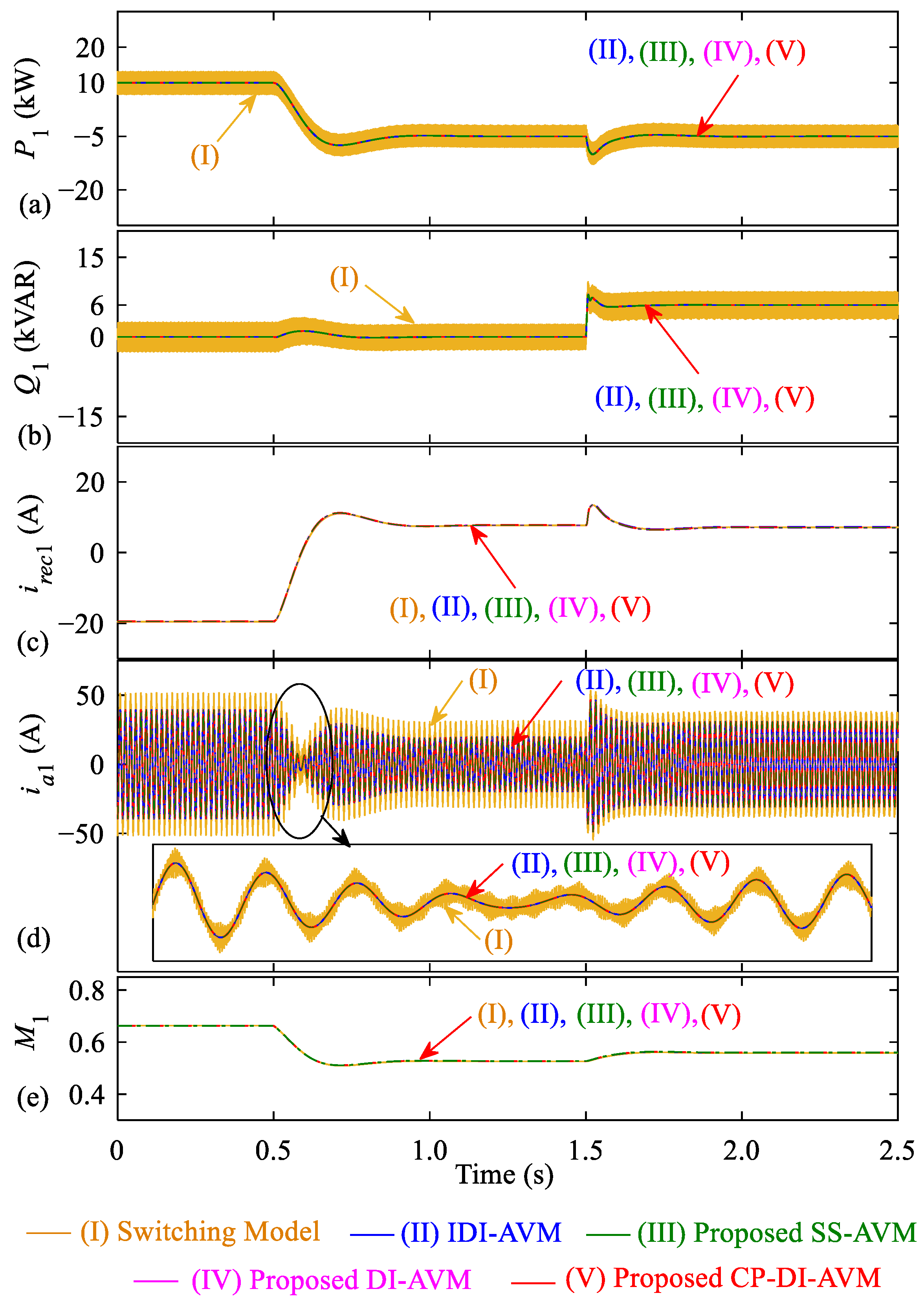
3.3. Numerical Accuracy Under Controller Dynamics
Here, the performance of the proposed models is investigated under the dynamics of the controllers. In
Section 3.1, a fixed modulation index was used while changing the power angle
δ. To consider the controller dynamics, the active and reactive power control schemes are implemented as demonstrated in
Figure 15, where the modulation index
M and power angle
δ are calculated as the outputs of the controllers to regulate the active and reactive power. The parameters of the PI controllers are summarized in
Appendix A. It is also noted that to adopt a control method other than the SPWM (e.g., space vector modulation), (5) can be used to calculate
M appropriately.
It is assumed that the system initially operates in a steady state where the setpoints of the active and reactive power are and , respectively, for VSC1. This corresponds to transferring 10 kW into the ac grid without reactive power exchange. Then, at t = 0.5 s, the active power setpoint is changed to to absorb active power from the grid, while maintaining the reactive power setpoint at zero. Then, at t = 1.5 s, the reactive power setpoint is changed to to inject reactive power into the grid, while maintaining the active power setpoint unchanged at .
The transient response of VSC1 variables (active and reactive power, rectified dc as well as ac currents, and the converter modulation index) obtained by the detailed switching model, and the AVMs run with a time-step size of
are shown in
Figure 16. As observed, the active and reactive power follow their setpoints effectively while adjusting the converter modulation index
M, as seen in
Figure 16e. It is also seen that the AVMs provide results consistently with those obtained by the detailed switching model.
The results obtained by the proposed SS-AVM and DI-AVM at a large simulation time-step size of
are also shown in
Figure 17, compared to the reference AVM solution obtained with
. As seen, the proposed AVMs are able to capture fairly accurate results compared to the reference solution, while the traditional IDI-AVM was numerically unstable.
3.4. Computational Speed
To compare the computational complexity of the four subject AVMs of VSCs, the CPU time per step in the transient simulations of
Figure 8 for different numbers of VSCs (indexed as
n) has been calculated, as summarized in
Table 1. The simulations are executed on a computer with an Intel
® Core™ i9-14900 @2.0 GHz processor, 32 GB RAM, and in PSCAD V5.0.2.
As shown in
Table 1, with the addition of more VSC systems in
Figure 8 (i.e., increasing
n), the CPU time per step increases due to the higher number of nodes in the network solution. Additionally, it is observed that the proposed CP-DI-AVM is comparable to the conventional IDI-AVM in terms of computational speed, and in some cases, it is even slightly faster. This is because both models result in a constant conductance matrix, while the computations in (24)–(27) for the CP-DI-AVM are comparable to those in (3), (4), (9), and (10) for the IDI-AVM.
It can also be observed in
Table 1 that the proposed SS-AVM and DI-AVM are computationally more demanding than the IDI-AVM and CP-DI-AVM, with a steeper increase in computational burden as the number of VSCs (and nodes) increases. This is due to their variable conductance matrix that needs to be recomputed at every simulation time step. The DI-AVM also requires lower computational resources compared to the SS-AVM, especially for larger systems, because the SS-AVM requires more computations for the history terms in (16).
4. Discussions
Overall, the conventional IDI-AVM may be the easiest among the subject models to implement; however, its accuracy degrades quickly with increasing the simulation time-step size, and it is not suitable when medium-to-large step sizes (~100–1000 µs) are required in the EMT studies. The proposed CP-DI-AVM has a computational speed comparable to that of the IDI-AVM and is also relatively straightforward to implement. Meanwhile, the CP-DI-AVM can be used with step sizes up to medium (~150–200 µs) without numerical instability, although the accuracy may be slightly compromised at these medium step sizes. Alternatively, the proposed SS-AVM can provide highly accurate results even at large time-step sizes (up to ~1000 µs), although its implementation may be quite complicated, involving a variable conductance matrix and several history current injections, which also require higher computational resources. The proposed DI-AVM offers similar accuracy to the SS-AVM while being numerically more efficient and easier to implement (as a conductance matrix only). Additionally, it is very accurate and numerically stable at large time-step sizes.
When selecting the proper interfacing technique for AVMs of VSCs in EMT simulations, it is also important to note that the variable conductance matrices in the SS-AVM and the DI-AVM may require considerably higher computations compared to the IDI-AVM and CP-DI-AVM, particularly when the network (i.e., the size of the overall system conductance matrix) is large. Therefore, their computational savings (owing to the allowance of large step sizes) should be considered along with their computational burden (resulting from their time-varying matrices).
It may be reasonable to conclude that the proposed DI-AVM is the best candidate when large time-step sizes are required for a system that is not very large (i.e., does not have many nodes) so that the size of the time-varying matrices is computationally manageable. Meanwhile, the proposed CP-DI-AVM is the best candidate when variable matrices are a concern (e.g., in networks with many nodes or buses or in real-time simulations), but very large time-step sizes are not required.
The fact that the proposed models do not assume that a dc capacitor must be in the model is an advantage in terms of modeling because it does not restrict the models to a certain configuration and provides flexibility to the user to choose what to connect to the dc terminal. Obviously, if a capacitor is connected to the dc terminal of the VSC, the same capacitor can also be connected to the dc terminal of the proposed models as an external circuit component, which has been the case in the case-study system in
Figure 8 used for the validations. Also, assuming that the SS-AVM requires a series
RL impedance or that the DI-AVM and CP-DI-AVM require a series
R resistor in their ac terminals as part of the models is not a critical restriction, because in practice the conductors and cables have impedances, which can be considered what is needed in these models.


