3.1. Operation Principle of EMG and P-TENG
The EMG energy harvesting system is based on Faraday’s law of electromagnetic induction. Faraday’s law of electromagnetic induction can be expressed in Formula (3). It drives the permanent magnet rotor to rotate through the rigid coupling between the sun gear and the shaft in the planetary gear system, causing the magnetic flux in the copper coil to change periodically with the angular displacement of the rotor, thereby generating an alternating induced electromotive force in the coil [
29,
30]. As shown in
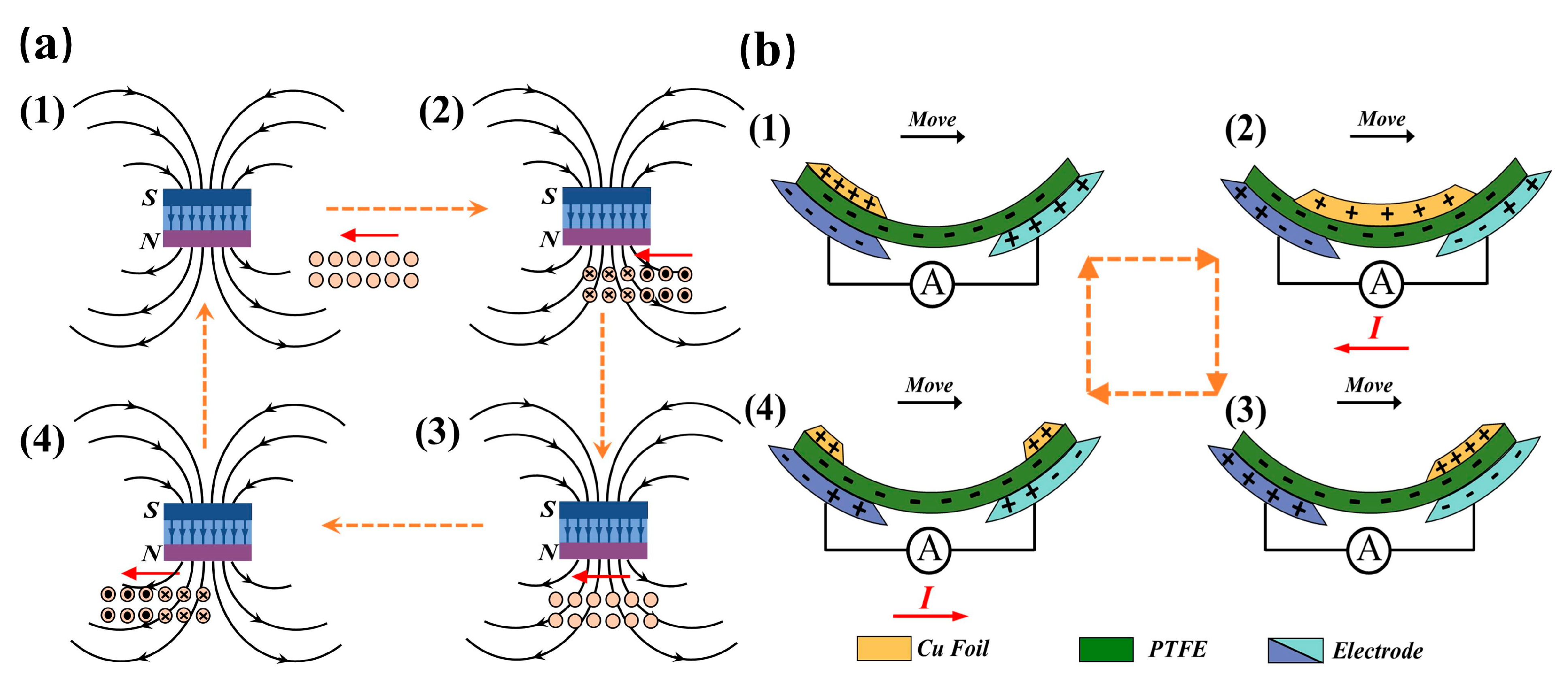
Figure 3a, in the relative motion of the permanent magnet and the coil, when the magnet and the coil axis are relatively far away from each other, the magnetic flux through the coil exists, but the rate of change is almost zero, so there is no induced current in the coil (1). With the beginning of the rotation of the rotor, the distance between the magnet and the coil gradually becomes smaller and smaller, the angle between the two continues to narrow, and the magnetic flux through the coil shows an exponential upward trend. The magnetic flux through the coil increases exponentially, and this process of magnetic flux increase stimulates a positive induced current in the coil (2). When the direction of the magnetic poles completely coincides with the coil axis, the magnetic flux reaches the maximum value in the whole cycle, but because the whole coil is equivalent to the cutting of magnetic inductance in the constant magnetic field, the rate of change in magnetic flux is zero, so it does not produce induced currents (3). The rotor continues to rotate so that the magnetic poles gradually deviate from the coil axis and the magnetic flux. With the exponential decline, the coil will be induced in the opposite direction of the current (4), until the coil is gradually away from the magnetic poles, the rate of change in magnetic flux drops abruptly, back to the initial state, the induced current also disappeared, and thus a complete cycle of electromagnetic induction is completed.
where
ε is the induced electromotive force,
is the rate of change in magnetic flux with time, and N is the number of turns of the induction coil. As the conductor loop moves through the magnetic field, the magnetic flux
changes, resulting in an induced electromotive force. When the kinetic energy generated by the corn seeder drives the magnet-equipped rotor to rotate in one direction, it periodically alters the magnetic flux in the Cu coil in the EMG, inducing an electromotive force and generating a periodic alternating current.
The operating mechanism of P-TENG follows the independent layer mode of TENG. Its core principle stems from the contact electret and electrostatic induction coupling effects caused by the difference in electronegativity between different materials: when two material layers undergo relative motion during contact separation, electrons transfer due to differences in surface electron affinity energy, thereby forming an electrostatic charge distribution at the interface. During separation, the charge imbalance drives charge carriers to migrate through the external circuit, generating measurable current and voltage outputs [
31,
32]. Taking the copper foil and PTFE dielectric friction layer system as an example, the power generation process is essentially a physical process of charge transfer induced by the difference in electron affinity between copper and PTFE. In this study, when the planetary gear’s toothless section is stationary in the initial state, no contact occurs at the friction interface, and the charge transfer process remains dormant. When the planetary carrier drives the planetary gear to rotate, the copper foil attached to the gear surface moves sequentially across the PTFE dielectric layer on the surface of the interdigitated electrodes as the mechanism moves. Due to the inherent differences in electron gain/loss capabilities between PTFE and copper foil, electrons migrate directionally from the copper foil surface to the PTFE surface upon contact, causing PTFE to accumulate negative charges while the copper foil becomes positively charged [
33]. This charge separation state forms a periodic cycle of charge induction and release as the gear rotates, manifesting as a regular current output characteristic in the external circuit.
In essence, the theoretical foundation of TENG lies in the Maxwell displacement current. By transforming the differential form of the Maxwell–Ampere law equations, we obtain Formula (4).
where
is the Maxwell displacement current density,
is the potential shift vector,
is the dielectric constant of the dielectric,
is the electric field strength, and
is the polarization field density.
is the current induced by the polarization field generated by the electrostatic charge carried by the surface, which is the fundamental theoretical basis and source of TENG. In fact, the actual mathematical model of TENG involves more complex factors such as additional parameters, nonlinear effects, and different friction material properties. The basic principles presented here provide a foundation for understanding TENG and its practical applications.
As shown in
Figure 3b, during the rotation of the copper foil in the direction of the planetary gear, in the initial state when the copper foil is in contact with the left electrode (1), the negative charges in the circuit are directed to collect in the corresponding contact area of this electrode by electrostatic interactions. As the copper foil rotates and comes into contact with the right electrode (2), the negative charge migrates to the newly contacted right electrode with the help of the load circuit, thus forming a current directed to the left. When the copper foil completely covers the right electrode (3), the potential difference between the two electrodes tends to disappear due to the dynamic equilibrium of the charge distribution, and the directional flow of charge is then stagnant. When the copper foil continues to rotate and comes into contact with the left electrode again (4), the negative charge, driven by the electrostatic induction effect, flows back to the initially contacted left electrode area through the load circuit, generating a current in the right direction. This cycle realizes the cyclic transfer process of negative charge between different electrodes. It is worth noting that the negative charge on the surface of PTFE in a stationary state can neither change the intrinsic induced potential distribution between the electrodes nor provide power support for the directional movement of the charge. It can be seen that the rotational behavior of the positively charged copper foil is the core driving force that triggers the directional transfer of charge and contributes to the formation of current, which plays a key role in the initial process of electrical energy generation in P-TENG. The COMSOL 6.1 simulation results of the corresponding states have been analyzed in detail by Wu et al. [
33,
34].
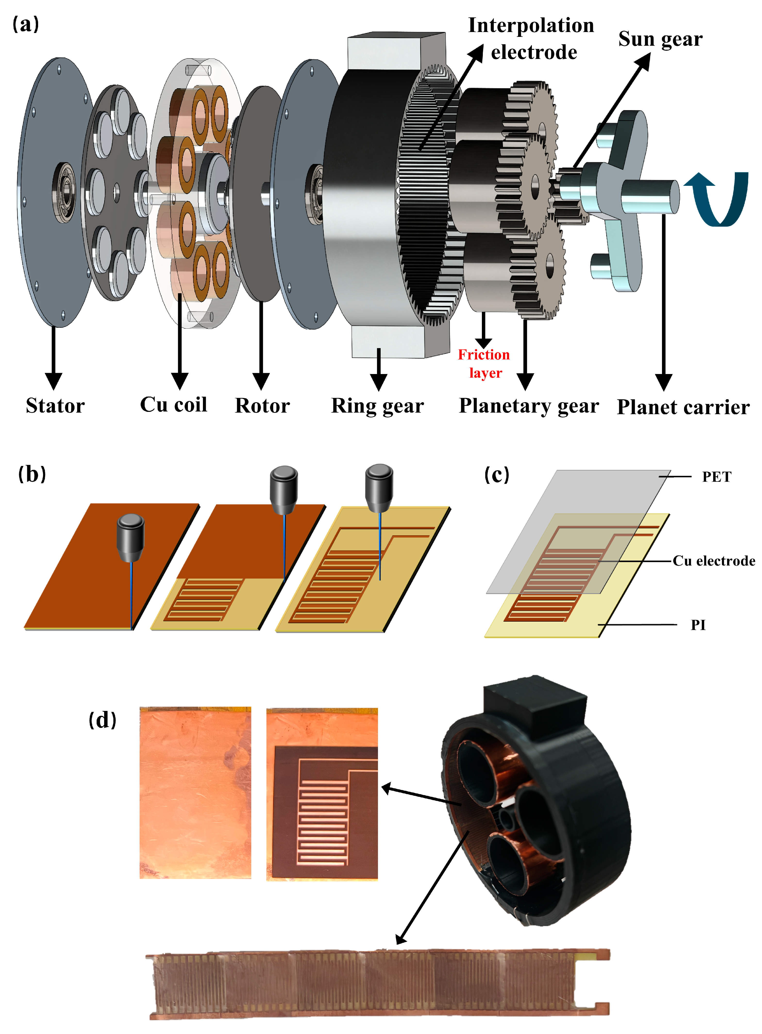
Additionally, to address the application requirements of the P-TENG adapter gear ring’s narrow inner diameter space, a rolling structure with interdigitated electrodes arranged along the inner wall of the gear ring was adopted to replace the traditional planar sliding design. Although the reduced contact area decreases the induced charge quantity, the interdigitated structure completes the power generation cycle through single-grid displacement, thereby enhancing the electronic reciprocating frequency and charge transfer efficiency [
35,
36]. Furthermore, by establishing an adjustable correlation between the copper foil sweeping speed and the planetary carrier rotational speed based on tooth count parameters, the relative speed is precisely matched to achieve maximum power generation. By synergistically regulating the charge transfer cycle through the coordination of planetary gear tooth count and rotational speed, combined with the synergistic effect of multiple electrodes, power generation performance is significantly enhanced, making it an optimal solution for power generation in confined spaces [
37,
38].
3.2. EMG and P-TENG Performance
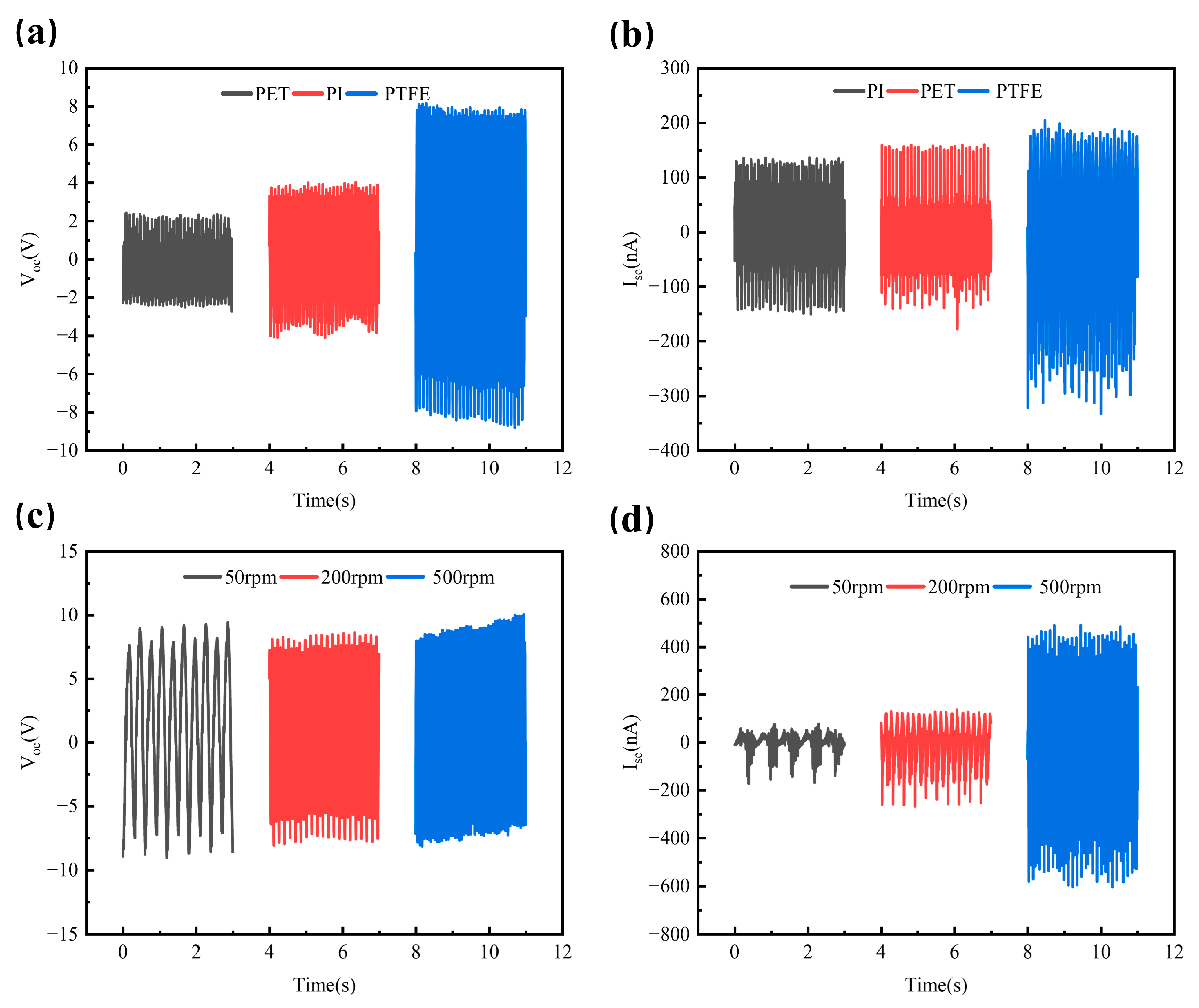
To investigate the power generation performance of P-TENG driven by the rotational motion of a seeding machine, the experiment used a high-sampling-frequency electrometer to collect real-time voltage and current signals. A stepper motor with adjustable speeds ranging from 30 rpm to 500 rpm was used to drive the planetary frame, simulating the performance of a seeding machine under different operating conditions. As shown in the experimental data in
Figure 4a,b, when the stepper motor speed is fixed at 300 rpm, the dielectric material significantly affects the power generation performance of the P-TENG. When PET and PI are used as the dielectric layer, the open-circuit voltage of the P-TENG reaches 2.8 V and 3.9 V, respectively, with short-circuit currents of 153 nA and 124 nA, respectively. However, when PTFE was used as the dielectric layer, the open-circuit voltage of the TENG increased to 8.6 V, and the short-circuit current rose to 224 nA, demonstrating superior power generation performance and providing data support for the application of this structure in real-world scenarios. The above study clarified the mechanism by which dielectric materials influence the power generation performance of P-TENG. However, in the actual operation of seeding machinery, the planetary frame speed undergoes dynamic changes. Therefore, investigating the power generation characteristics of P-TENG within the speed range of 30 rpm to 500 rpm and quantifying the relationship between speed and electrical output is of significant importance for enhancing its operational adaptability and energy conversion efficiency.
As shown in the experimental data in
Figure 4c,d, when the rotational speed of the P-TENG friction layer varies between 50 rpm and 500 rpm, the peak Isc increases significantly from 61 nA to 532 nA as the rotor speed increases, while Voc remains stable at around 8.5 V. This phenomenon fundamentally stems from the characteristic differences between Voc and the short-circuit current Isc. Voc depends on the maximum overlap area between the PTFE film and the copper finger-shaped electrodes. In the experiment, the fixed structure keeps this area constant, resulting in a stable induced charge quantity and a constant potential difference between the electrodes; hence, Voc remains at approximately 8.5 V. Isc, however, is directly related to the charge transfer rate. Increasing the rotational speed significantly increases the friction frequency, accelerating the charge transfer rate, and causing the Isc peak to increase from 61 nA to 532 nA. This demonstrates the characteristic that voltage output depends on structural parameters while current output responds dynamically to changes. Thanks to the excellent properties of the dielectric layer PTFE film, including non-stickiness, high-temperature resistance, and low friction coefficient, the P-TENG has a stable operational foundation. As shown in the durability test data in
Table 1, after continuous operation at a speed of 500 rpm for 4 h, the average Voc and average short-circuit current Isc remained relatively stable compared to the initial operating stage, with no significant sharp decline. The overall performance was approximately 92% of the initial state, which fully verifies the durability of P-TENG. For the power output performance of P-TENG, at 200 rpm, the peak power reached 1.71 μW. Although this power level is far below that of traditional power generation systems, in scenarios such as low-power IoT nodes in open farmland or remote sensing devices in remote areas, the output energy, when effectively managed, can meet the operational requirements of certain electronic devices, providing a feasible energy solution for distributed self-powered systems.
Additionally, the number of interdigitated electrodes plays a crucial role in regulating the output performance of P-TENG. We conducted a systematic investigation into the output characteristics under different electrode configurations, with experimental results shown in
Table 2. The Voc of P-TENG does not exhibit a significant increasing trend and remains stable at approximately 8 V. This is primarily determined by the core mechanisms, namely, the surface charge density of the friction material and the interlayer spacing of the friction layer, which are weakly correlated with the number of electrodes; while the Isc exhibits a characteristic of first increasing and then stabilizing as the number of electrodes increases. This is because, in the initial stage, the expansion of the total effective area of the electrodes enhances capacitance and its rate of change, while the edge field effect is strengthened, synergistically promoting charge transfer rates and increasing the Isc. However, once the number of electrodes reaches a critical value, the overlapping of edge fields between adjacent electrodes leads to a diminishing return in edge effect gains, and the total charge quantity of the friction layer imposes an upper limit constraint, resulting in a slowing and stabilization of the Isc growth.
Using a stepper motor as the excitation source for a simulated seeder, the output characteristics of the EMG were investigated.
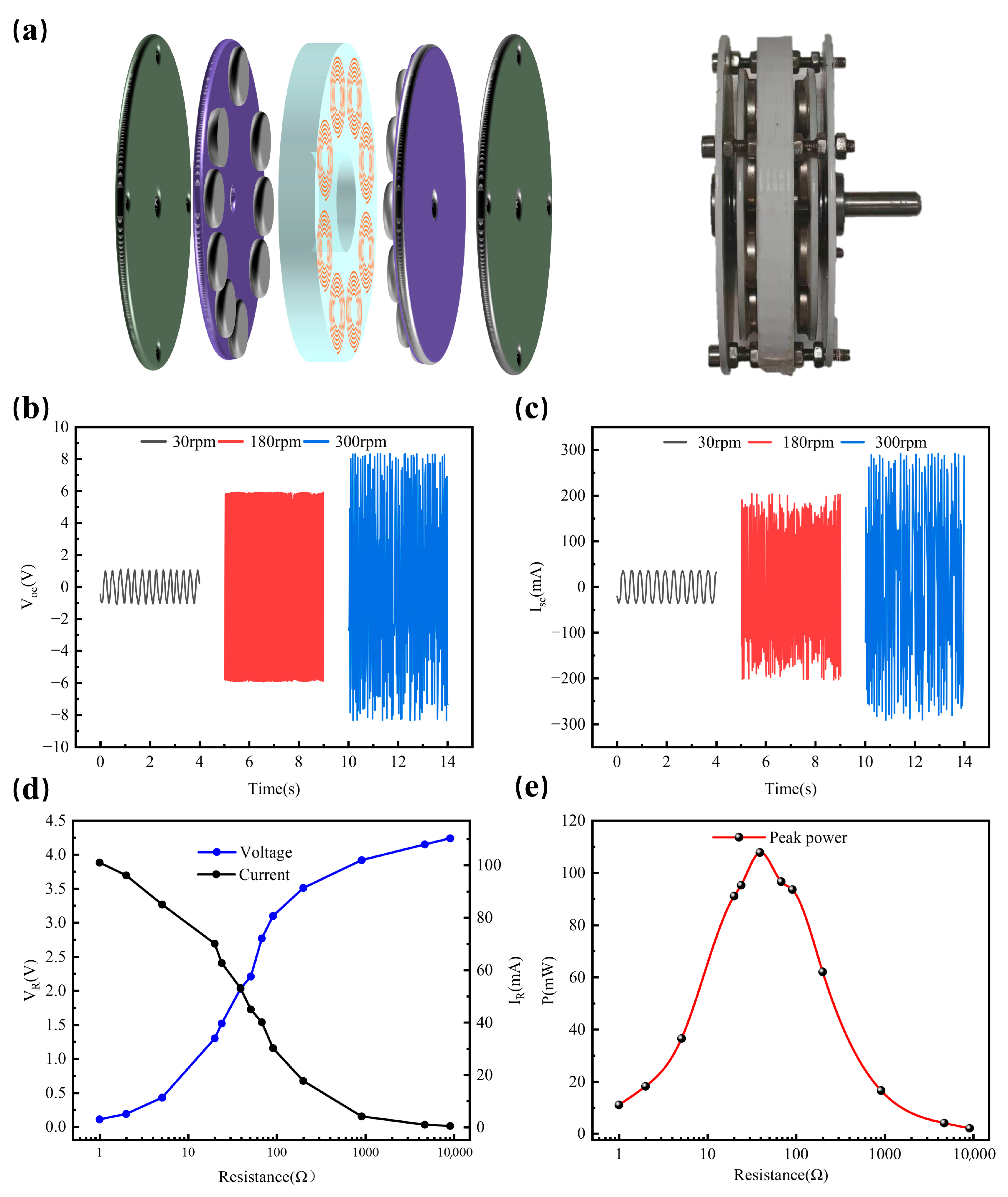
Figure 5a shows the structural diagram of the EMG section. As shown in the experimental data in
Figure 5b,c, the output performance of the EMG is positively correlated with rotational speed. When the rotational speed increases from 30 rpm to 300 rpm, Voc increases from 1 V to 8.7 V, and Isc increases from 45 mA to 294 mA. Similar to P-TENG, durability performance was conducted on the EMG. After continuous operation for 4 h, the EMG performance showed no significant degradation, verifying its excellent stability. To further investigate the performance of the EMG under different load resistances in practical working scenarios, as shown in the results of
Figure 5d,e, as the load resistance increases, the load voltage shows an upward trend, while the load current decreases accordingly, providing key performance parameters for optimizing EMG applications. In studies of the EMG’s maximum output power, at a rotational speed of 200 rpm, when the load resistance was 31.5 ohms, the maximum peak power reached 110 milliwatts. This substantial power output enables the EMG to rapidly inject electrical energy into microcapacitors of varying capacities. With this efficient charging capability, it can reliably power the sensing system, ensuring continuous and reliable operation of sensor monitoring and data transmission.
3.3. System Application Performance
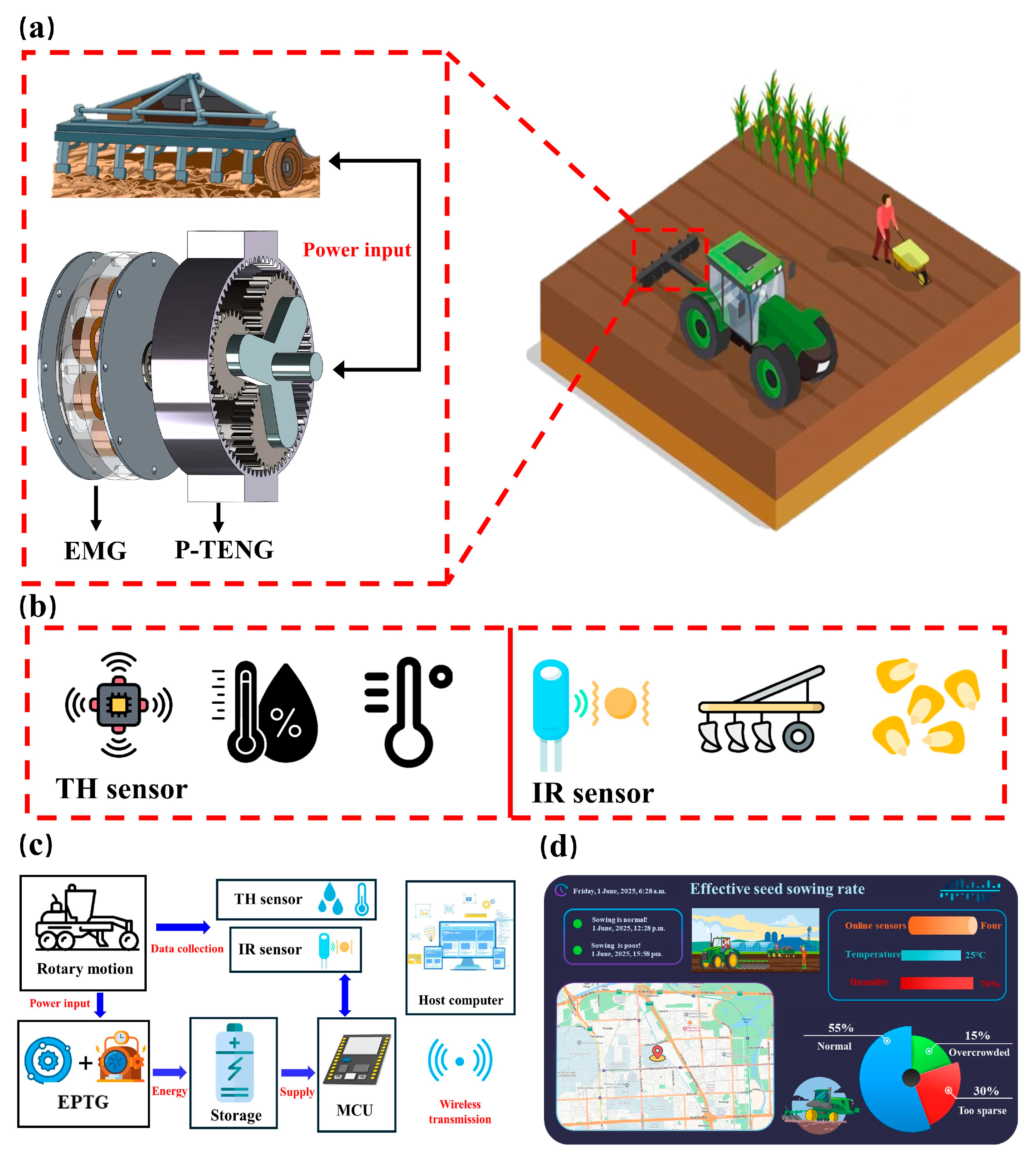
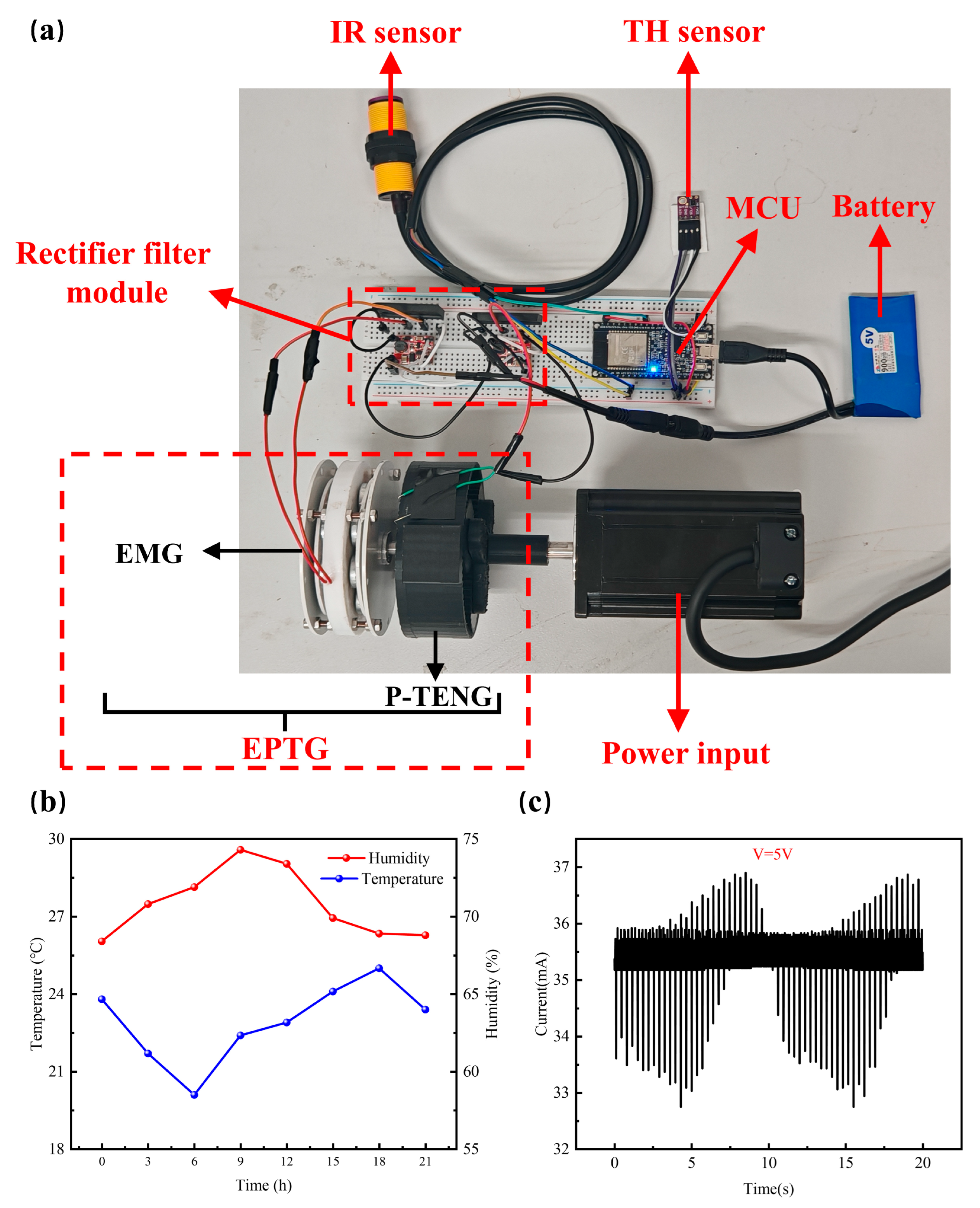
To validate the suitability of the EPTG self-powered wireless sensing system for corn seeding applications, a test system was constructed as shown in
Figure 6a. In agricultural mechanization operations, a stable energy supply is the core foundation for the long-term operation of sensing systems [
39]. This sensing system uses EPTG as the core self-powered unit. This unit employs a coupled design of P-TENG and EMG, utilizing the mechanical energy generated by the rotation of the seed dispenser during corn seeding machine operations to drive the EPTG, thereby achieving efficient capture and conversion of mechanical energy. The captured energy is processed through a rectification and filtering module for waveform correction and noise filtering, then boosted in voltage via a voltage-boosting module before being directed to charge a 5 V 900 mAh energy storage battery. This energy storage battery serves as an auxiliary energy storage unit, reducing the impact of instantaneous mechanical energy fluctuations on power supply stability. Based on an energy management strategy, it stores excess energy when mechanical energy is abundant and releases energy when mechanical energy is scarce, establishing a closed-loop system from energy capture and storage to a stable power supply, ensuring the continuity and stability of the system’s energy supply. The stable electrical energy output by the energy storage battery powers the IR sensor, TH sensor, and MCU. The IR sensor collects non-contact monitor parameters such as corn seeding spacing and seeding density, while the TH sensor precisely collects environmental temperature and humidity data. The multi-dimensional environmental information collected by both sensors is preliminarily processed by the MCU, then wirelessly transmitted to the cloud platform for visualization analysis. This provides foundational sensory data for subsequent corn seeding decisions, thereby validating the adaptability of the EPTG self-powered wireless sensing system in corn seeding scenarios, from energy supply to information sensing.
- (1)
EPTG output power
To evaluate the energy supply efficiency of the EPTG self-powered system in corn seeding applications, a test platform for power output monitoring and charging management was constructed. The system is based on an innovative coupling design of P-TENG and EMG, which converts the rotational mechanical energy of the seeder’s transmission components into alternating current. After optimization through rectification, filtering, and a boost module, the system conducts output power characteristic tests using an external variable load. Output power tests were conducted under typical operating conditions of a corn seeder (average rotational speed of 25 rpm). To enhance mechanical energy conversion efficiency and meet high-power output requirements, a planetary gear transmission structure was adopted for speed amplification and torque regulation. Through theoretical calculations and experimental verification, the following parameters were selected: 140 teeth for the ring gear, 60 teeth for the planetary gear, and 20 teeth for the sun gear. These parameters effectively enhance the power output of the energy capture components. Test results show that the optimized EPTG system achieves a stable power output of 105 mW under these operating conditions. Through charging mode verification, this power output ensures that a 900 mAh battery receives continuous effective energy replenishment during a typical operating cycle, providing a reliable energy supply for the stable operation of self-powered sensing devices. This fully validates the engineering applicability and energy supply reliability of the EPTG system in agricultural machinery applications.
- (2)
Power consumption of sensing system
To address the low-speed operation characteristics of corn seeders, the sensing system adopts a low-power strategy combining deep sleep mode with intermittent wake-up. The microcontroller enters a deep sleep mode with microampere-level current consumption during non-operational periods, resulting in extremely low power consumption. It only briefly wakes up during data collection and transmission, as shown in
Figure 6c, where the current exhibits periodic fluctuations between 34 and 37 mA, corresponding to an instantaneous power consumption of approximately 170 mW. This strategy significantly reduces the system’s average power consumption, keeping it within the coverage range of the EPTG’s stable output power of 105 mW. Combined with the energy storage and buffering effect of a 900 mAh battery, this creates a dynamic balance between energy harvesting, energy storage, and low-power consumption, providing reliable energy assurance for the long-term stable operation of the sensing device. This fully validates the effectiveness of this low-power strategy in enhancing the self-powered system of the EPTG.
- (3)
Data transmission
To assess the reliability of wireless transmission of sensor data in an open field corn seeding scenario, this test verifies the transmission stability and anti-interference performance under different environmental conditions. A high-performance corn seeding sensing system must have a long effective communication distance and strong anti-interference capabilities. The test results are shown in
Table 3. In open farmland, the WIFI module and the sensing system achieved an effective communication distance of 60 m, enabling stable transmission of data such as seeding density, spacing, and environmental temperature and humidity. However, when the transmission distance exceeded 60 m, the packet loss rate (PLR) significantly increased, leading to communication interruptions. In densely populated agricultural machinery operation areas, packet loss occurs at 20 m, and transmission stability drops sharply beyond 30 m, making it difficult to ensure the real-time integrity of decision-making data. In actual seeding fields, the density of agricultural machinery equipment is lower than in the densely populated operation areas of the experiment, resulting in weaker signal interference intensity. This reduces interference during sensor data transmission, improves communication quality, and achieves a more optimal effective transmission distance compared to the experimental scenario [
40,
41].
- (4)
Sensor module
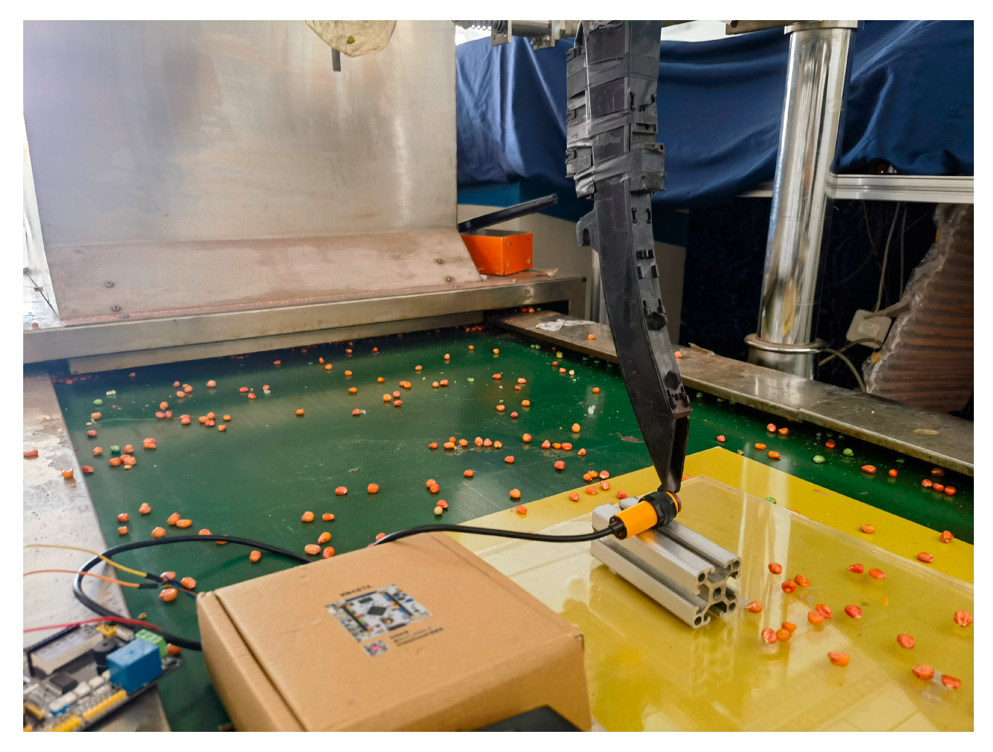
To validate the collaborative application performance of the designed sensor module in corn seeding operations, an experimental platform was constructed integrating an E18-D80NK infrared reflective photoelectric sensor, an ESP32 main control unit, and an SHT30 temperature and humidity sensor. This platform simulates the dynamic scenario of seeds falling from the seeding tube in a field. As shown in
Figure 7, the photoelectric sensor is deployed at the exit of the seed distribution channel. When seeds fall and block the infrared light path, it triggers a change in the signal level, enabling seed detection. The temperature and humidity sensors are installed around the seed dispensing tube to simultaneously collect environmental temperature and humidity data during the operation. The signals collected by both sensors are processed by the MCU and displayed in real time on the upper-level computer cloud platform, showing seeding density, seeding spacing, and environmental temperature and humidity information. A 200 ms anti-vibration mechanism is also set to filter out false triggers caused by equipment vibration or repeated seed obstruction.
To verify the recognition accuracy of the IR photoelectric sensor in corn seeding operations, the experimental platform used 200 uniformly sized, intact corn seeds per group as standard samples and conducted three independent trials. The results showed that the photoelectric sensor recognized 185, 192, and 187 seeds, respectively, with an average recognition accuracy of 94%. This result indicates that the photoelectric sensor can accurately identify the seed drop situation of corn seeds, providing reliable data support for seeding monitoring.
The performance of temperature and humidity sensors involves comparing the collected data with standard equipment to verify accuracy, with deviation values falling within the permissible range. As shown in
Figure 6b, the system can stably collect temperature and humidity data throughout the day. It is worth noting that temperature and humidity sensors not only monitor the sowing environment in real time but also provide critical evidence for analyzing the impact of environmental conditions on sowing quality: high humidity may cause water vapor to adhere to the seed surface, interfering with the blocking effect of the infrared light path; and temperature changes may alter the physical properties of seeds (such as hardness and elasticity), thereby affecting their falling posture and speed in the seed dispensing channel. By synchronously collecting seed dispensing data and temperature and humidity parameters, this lays the foundation for subsequent development of accuracy compensation models and optimization of seeding operation parameters.
In summary, this sensing system achieves precise monitoring of the seed falling process and simultaneous acquisition of environmental temperature and humidity data, providing technical support for intelligent sowing monitoring and creating conditions for environmental adaptability analysis. It has certain application value in the field of agricultural intelligent equipment.
