Abstract
Wireless power transfer (WPT) systems for autonomous underwater vehicles (AUVs) are gaining traction in marine exploration due to their operational convenience, safety, and flexibility. Nevertheless, disturbances from ocean currents and marine organisms frequently induce rotational, axial, and air-gap misalignments, significantly degrading the output power stability. To mitigate this issue, this paper proposes a novel reconfigurable WPT system utilizing coaxial antipodal dual DD (CAD-DD) coils, which strategically switches between a detuned S-LCC topology and a detuned S-S topology at a fixed operating frequency. By characterizing the output power versus the coupling coefficient (P-k) profiles under both reconfiguration modes, a parameter design methodology is developed to ensure stable power delivery across wide coupling variations. Experimental validation using a 1.2 kW AUV charging prototype demonstrates remarkable tolerance to misalignment: ±30° rotation, ±120 mm axial displacement, and 20–50 mm air-gap variation. Within this range, the output power fluctuation is confined to within 5%, while the system efficiency exceeds 85% consistently, peaking at 91.56%.
1. Introduction
Autonomous underwater vehicles (AUVs) are indispensable tools for marine resource exploration and development, exhibiting remarkable maneuverability and robust environmental adaptability [1,2]. However, stringent requirements for miniaturization and weight reduction inherently limit their onboard energy capacity, severely constraining their operational endurance [3,4]. Wireless power transfer (WPT) technology presents a transformative solution for AUV recharging, eliminating the physical connectors and cables associated with conventional conductive charging. This approach offers significant advantages in underwater applications, including inherent electrical safety, operational flexibility, and enhanced reliability [5,6,7,8,9,10]. Furthermore, underwater WPT enables charging within the marine environment itself, leveraging the seabed’s complexity to support covert AUV operations. Consequently, this technology effectively addresses the critical challenge of sustained AUV mission capability through remote energy replenishment [11,12,13,14].
The dynamic marine environment, significantly more complex than air, subjects AUVs to unavoidable misalignments during docking—including rotation, axial displacement, and air-gap variation. These misalignments drastically reduce the coupling coefficient between the transmitter and the receiver coils, posing a fundamental challenge to stable power delivery. Existing mitigation approaches encompass control strategies, magnetic coupler innovations, and compensation topology designs. Control-based methods [15,16,17] offer precise power regulation but suffer from algorithmic complexity and efficiency degradation under large misalignments due to the limited modulation range. Innovations in magnetic couplers, such as the rotatable structures proposed by Yan et al. [18,19], address rotational shifts but inherently restrict axial displacement tolerance due to their close-coupled ferrite cores; their substantial weight also hinders practical AUV integration. While Wu et al. [20] demonstrated improved tolerance (±30° rotation, ±30 mm axial offset) using an overlapping DQ transmitter and dipole receiver, this required intricate docking mechanisms and offered limited axial range. Compensation-based solutions—including hybrid topologies [21,22,23], reconfigurable networks [24,25,26], and dual-frequency systems [27]—typically aim to create a plateau region in the output power versus coupling coefficient (P-k) curve. However, they often lack a rigorous parameter design methodology to maximize the achievable misalignment tolerance. Furthermore, studies utilizing detuned compensation [24,25,26] frequently overlook its critical impact on component stresses and system design. Clearly, enhancing power stability across wide misalignment ranges demands synergistic improvements beyond any single technical domain.
To address these challenges, this work introduces a reconfigurable WPT system featuring coaxial antipodal dual DD coils with hybrid ferrite–nanocrystalline cores. The magnetic structure co-optimizes the misalignment tolerance and weight constraints through a multiphysics design. Operating at 85 kHz, the system dynamically switches between detuned S-LCC and S-S topologies. A novel parameter design method ensures seamless overlap of the P-k curves at transition points, while comprehensive analysis quantifies the detuning effects on component stress. Experimental validation via a 1.2 kW prototype confirms the design’s operational robustness.
2. Magnetic Coupler Design
The magnetic coupler constitutes the cornerstone of underwater WPT systems, with its electromagnetic characteristics dictating the overall power transfer performance [28]. To address the hydrodynamic contour constraints of AUV hulls, a novel coaxial antipodal dual DD (CAD-DD) coil configuration serves as the core coupler architecture. Figure 1 illustrates this topology while defining three critical misalignment degrees of freedom: rotational misalignment (dθ), axial displacement (dx), and vertical air-gap variation (dz). Accounting for underwater operational requirements, a precisely engineered inter-coil clearance d mitigates hydrostatic pressure on the waterproof housing. More details will be discussed in Section 5.
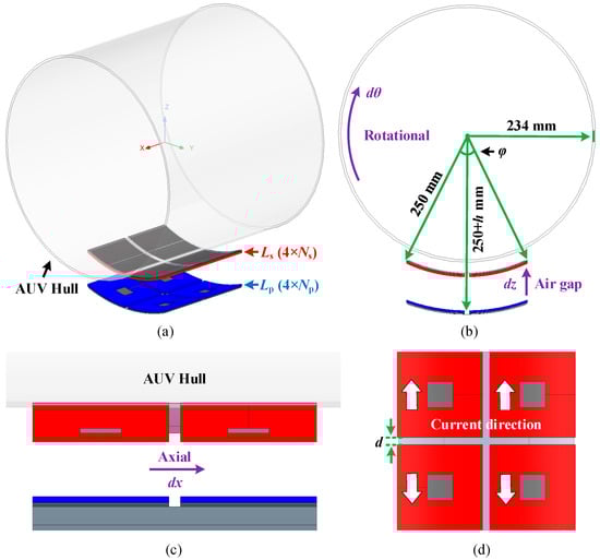
Figure 1.
Magnetic coupler with CAD-DD coils configuration: (a) overview; (b) +X view; (c) +Y view; and (d) +Z view.
This innovative coupler integrates two geometrically identical DD coils arranged coaxially with opposing current polarities. The antipodal configuration simultaneously expands the effective coupling area while enforcing vector cancellation of stray fields. As evidenced by the reconstructed flux lines and magnetic flux density distribution in Figure 2 (XZ plane), the CAD-DD coils fundamentally restructure the electromagnetic coupling pathways: leakage flux vectors are forcibly aligned with the primary coupling flux, elevating the average magnetic coupling intensity by 18.7% versus conventional DD structures [14]. Crucially, the field distribution homogenizes progressively under misalignment and enhanced flux linkage continuity during displacements. These mechanisms collectively achieve exceptional coupling strength while establishing unprecedented misalignment tolerance for AUV applications.
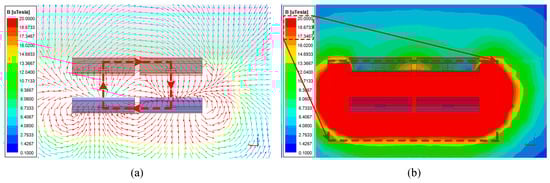
Figure 2.
Magnetic field distribution in XZ plane: (a) spatial distribution of magnetic field lines; and (b) distribution of magnetic flux density.
Beyond the coil geometry, magnetic core implementation demands the resolution of competing objectives: saturation resilience, receiver mass minimization, magnetic reluctance reduction, and high-frequency loss suppression. A hybrid ferrite–nanocrystalline laminated core structure tailored to the CAD-DD spatial profile resolves these requirements, as depicted in Figure 3. Ferrite segments interface directly with each DD coil winding periphery, conforming precisely to the four active regions. Nanocrystalline ribbons laminate onto exterior ferrite surfaces, strategically bridging interstitial zones between adjacent DD coil sections. This configuration establishes a continuous low-reluctance magnetic circuit while suppressing flux leakage. Critically, the layered material sequence—ferrite innermost, nanocrystalline outermost—exploits distinct electromagnetic properties. Initial flux penetration through high-permeability ferrite substantially attenuates the field intensity within the nanocrystalline material, effectively minimizing the characteristic eddy current losses [29]. Concurrently, the exterior nanocrystalline layer capitalizes on the exceptional specific saturation flux density [30]. Implementation of ultra-thin (0.2 mm) nanocrystalline laminates consequently achieves significant power density gains with a minimal associated mass penalty for host AUV platforms.
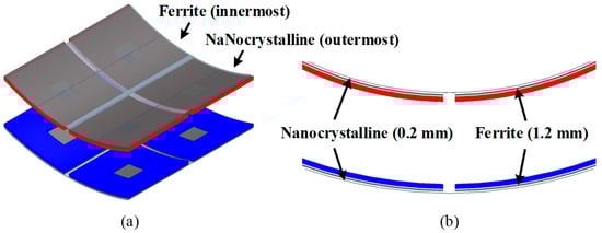
Figure 3.
CAD-DD based on a hybrid stacked magnetic core composed of flexible ferrite and iron-based nanocrystalline: (a) overview; and (b) +X view.
2.1. Parameter Optimization of CAD-DD
Ensuring robust misalignment tolerance while satisfying the stringent weight constraints for AUV receivers necessitates optimized structural parameters for the CAD-DD coils. Superior magnetic coupling performance constitutes the essential foundation for achieving high-power, high-efficiency energy transfer in WPT systems. Consequently, the parameter optimization principle for this magnetic coupler prioritizes maximizing coupling performance while strictly guaranteeing compliance with specified misalignment tolerance requirements. To quantitatively characterize the anti-misalignment capability, the coupling coefficient fluctuation ratio is defined as λ = kps0/kmin, where kmin and kps0 denote the coupling coefficients at the maximum permissible offset and at the nominal operating position, respectively.
As Figure 1 indicates, the optimizable CAD-DD coil parameters encompass primary turns (Np), secondary turns (Ns), geometric dimensions (coil angle φ and transmission distance h), and inter-coil gap (d). The optimization employs a constrained parametric sweep algorithm operating under fundamental electromagnetic design rules. The theoretical foundation initiates from minimal structural parameters (φ, Np, Ns), with mandatory satisfaction of the rated coupling coefficient kps0 serving as the primary filter condition during design space traversal. Each parameter exhibits distinct physical constraints and coupled interactions with optimization objectives:
- φ predominantly governs the magnetic coupling area and mutual inductance, yet it is strictly bounded by the 250 mm device footprint constraint.
- Np directly control the transmitter inductance and quality factor but face AC resistance and thermal dissipation boundaries.
- Ns dictate the receiver voltage gain and flux linkage, though scalability is limited by the physical coil thickness and proximity effects.
These interdependent nonlinear relationships render explicit characterization of individual/coupled effects fundamentally intractable, necessitating a strategic focus on Np, Ns, and φ.
The axial misalignment optimization procedure (Figure 4) initiates with specification of the system constants: operating frequency (f), nominal coupling coefficient (kps0), required fluctuation ratio (λ), angular bounds [φ1, φ2] (determined by the operational depth requirements and kps0), fixed transmission distance (h), fixed gap (d), and conductor diameters (dp, ds). A progressive angular iteration sweeps φ across [φ1, φ2] in 2° increments. For each φ value, exhaustive Np-Ns combinations undergo electromagnetic validation to identify parameter sets satisfying kps0 and arc length constraints at a 250 mm radius: 4dpNp ≤ 4.36φ-d and 4dsNs ≤ 4.36φ-d. All the valid tuples (φ, Np, Ns) are recorded and indexed (n = 1, 2, …N). Post-screening, each valid set undergoes misalignment robustness validation through axial displacement simulation (dx). This identifies the critical offset position (Xn) where minimum coupling (kmin) occurs. The core optimization target maximizes Xn to enhance the positional uncertainty tolerance. The optimal solution selects the parameter tuple achieving the maximum Xn. For equivalent Xn maxima, staged prioritization applies: first minimal φ (reducing eddy current losses), then minimal Ns (lowering receiver mass), and finally, minimal Np (optimizing transmitter compactness)—reflecting the electromagnetic loss hierarchies while addressing the multidimensional coupling complexities that preclude closed-form solutions.
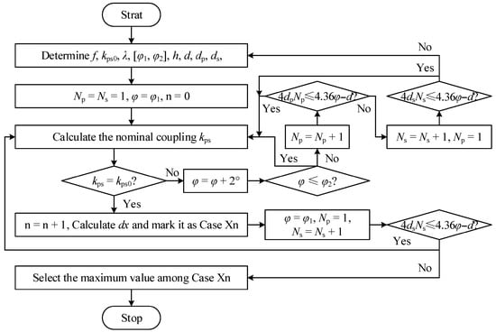
Figure 4.
Parameter optimization flowchart of CAD-DD.
2.2. Misalignment Tolerance Analysis of CAD-DD
This study establishes an explicit electromagnetic–structural co-design framework to derive the system parameters presented in Table 1. These values represent certified outputs of a rigorous iterative optimization process resolving critical multi-physics compromises between the coupling efficiency, pressure resilience, and spatial constraints through high-fidelity simulation validation.

Table 1.
Initial system parameters for coil optimization.
The baseline configuration emerges from resolving inherently antagonistic parameter relationships via electromagnetic FEA simulations and mechanical stress modeling. A representative challenge is the coil angle φ, which exhibits a non-monotonic tradeoff: increased values enhance the pressure containment efficiency by distributing mechanical loads, yet they simultaneously degrade the near-field coupling performance due to flux divergence. Such conflicts were systematically resolved through exploration in the φ-Np-Ns design space, constrained by industry-standard pressure vessel dimensions that mandate geometric conformity.
This physics-driven methodology achieves resonance frequency alignment within ±3% of the 85 kHz target while maintaining a significantly elevated nominal coupling coefficient across operational extremes—outcomes validated through adaptive meshing refinement in transient FEA simulations. The parameter selections directly trace to first-principles constraints: coil angle φ represents the spatial optimum where the pressure containment efficiency and mutual inductance decay gradients reach equilibrium, transforming Table 1 from initial estimates into certified optimization outputs.
Executing the parameter optimization procedure outlined in Figure 4 yielded three parameter sets achieving identical maximum dx values:
- Np = 11, Ns = 12, φ = 60°;
- Np = 10, Ns = 12, φ = 64°;
- Np = 8, Ns = 9, φ = 72°.
Guided by the lightweight design priority, the optimal parameter set was selected as Np = 11, Ns = 12, φ = 60°. Under ideal docking conditions within the recovery cage, the receiver coil Ls aligns coaxially with the transmitter coil Lp. Practical operations, however, introduce inevitable misalignment due to oceanic currents, marine fouling, limit switch tolerances, and docking inaccuracies, manifesting as rotational (dθ), axial (dx), and air-gap (dz) misalignments. Figure 5 presents the simulated and experimentally measured variations in the coupling coefficient under these misalignment modes for the optimal parameter set. All three misalignment types exhibit monotonically decreasing coupling coefficients with increasing displacement. Critically, the CAD-DD coil maintains robust performance within practical operational bounds:
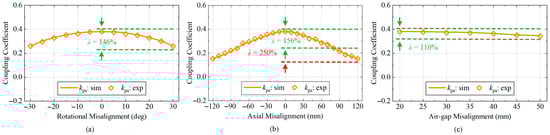
Figure 5.
Simulated and measured coupling coefficients varying with misalignments: (a) rotational misalignment; (b) axial misalignment; and (c) air-gap misalignment.
- Rotational misalignment (±30°): λ = 146%;
- Axial misalignment (±80 mm): λ = 156%;
- Air-gap misalignment (20–50 mm): λ = 110%.
These metrics confirm the exceptional intrinsic misalignment tolerance. However, when the axial displacement extends to dx = 120 mm, the fluctuation ratio escalates to 250%. At this threshold, the standalone magnetic coupler becomes insufficient for sustaining stable power transfer. This limitation necessitates integrating compensation topologies, discussed in Section 3—to further enhance the system-wide misalignment tolerance.
3. Reconfigurable Topology and Modal Analysis
Synergistically integrated with the CAD-DD coil, this work proposes a reconfigurable detuned S-LCC/S compensation topology, as depicted in Figure 6. The key components include the following: DC voltage source UD, inverter switches S1–S4, rectifier diodes D1–D4, filter capacitor CF, and battery-equivalent load Ro. The primary and secondary coils exhibit self-inductances Lp and Ls, respectively, coupled with mutual inductance Mps. The circuit currents are denoted as Ip, Is, and Ir, while the compensation elements comprise the capacitors (Cp, Cs, Cx, Cr) and inductor Lr. A single-pole double-throw (SPDT) relay S0 switches between Cx and Cr. The inverter’s fundamental output voltage is Uab, with Req representing the equivalent AC load preceding the rectifier.
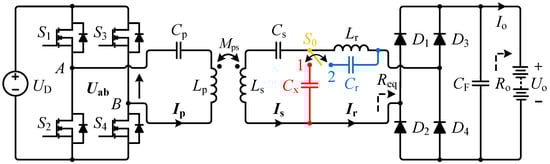
Figure 6.
Proposed reconfigurable S-LCC/S detuned topology.
Applying fundamental harmonic approximation yields:
Critically, the topology operates in two distinct modes governed by the relay configuration:
- Mode I (detuned S-LCC): Activated when S0 connects to Contact 1 (Figure 7a), requiring resonant conditions:
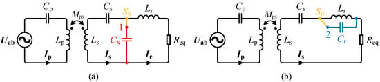 Figure 7. Equivalent circuit: (a) detuned S-LCC topology in Mode I; and (b) detuned S-S topology in Mode II.
- Mode II (detuned S-S): Engaged when S0 switches to Contact 2 (Figure 7b), governed by:
Equations (2) and (3) confirm that under an identical resonant frequency ω, relay switching reconfigures the secondary network topology (LCC ↔ S) while maintaining a detuned series-compensated primary. This enables dynamic reconfiguration between the detuned S-LCC and S-S operational modes.
3.1. Mode I: Detuned S-LCC Topology
Incorporating resonant condition (2) into (4) solves the loop currents:
Notably, as Mps → 0 (e.g., during AUV misalignment beyond tolerance or complete departure):
This eliminates the uncontrolled primary current surge characteristic of series-compensated topologies [21].
The input impedance Zin1 and phase angle θin1 derive from (6):
Constraint 0 < α < 1 ensures θin1 > 0, indicating inductive Zin1 that enables the zero-voltage switching (ZVS) capability.
Combining (1) and (6), the output power Po1 versus coupling coefficient kps is:
where and .
With Lp, Ls, Ro, UD, and ω as the design parameters, Po1 becomes a function of α and Cx at fixed kps. Differentiating Po1 (kps) yields the extremum point:
Po1 exhibits unimodal behavior—increasing then decreasing with kps—peaking at Po1max when kps = kex1:
Thus, parametric optimization of α and Cx creates a non-monotonic Po1–kps characteristic. Exploiting this plateau region sustains near-constant power delivery across a defined coupling range [kmin1, kmax1].
3.2. Mode II: Detuned S-S Topology
The circuit model for Figure 7b is:
where .
Solving with condition (3) gives the coil currents:
indicating the 90° phase lag of Ip relative to Is. The primary overcurrent protection at Mps → 0 remains consistent with (7).
The input impedance and phase are:
Confirming the inductive Zin2 and ZVS compatibility.
The output power versus coupling follows:
where and .
Similar to Mode I, Equation (15) produces a power plateau across [kmin2, kmax2]. The extremum points are:
Notably, kex2 ∝ √α while Po2max ∝ 1/α. Thus, increasing α elevates kex2 but reduces the peak power.
Both modes generate power plateaus over distinct coupling ranges. Strategic parameter design enables concatenation of these ranges ([kmin1, kmax1] and [kmin2, kmax2]), extending stable power delivery across a wider coupling variation interval through mode switching operation.
4. System Design and Switching Strategy
4.1. Circuit Parameter Design
This study establishes two fundamental principles for system parameter design:
- Maximizing the operable coupling variation range within constrained power fluctuation limits.
- Maintaining continuous and stable power transmission throughout the acquired coupling range.
To quantify the output power stability, the power fluctuation ratio γ is defined as:
where Pomax and Pomin denote the maximum and minimum allowable output power, respectively. To mitigate the overvoltage/overcurrent risks in AUV batteries, Pomax is set equal to the preset output power Poset.
Section 2 reveals that both reconfiguration modes exhibit smooth power output intervals corresponding to distinct coupling ranges ([kmin1, kmax1] and [kmin2, kmax2]). To ensure uninterrupted stable power delivery across an extended coupling range, these intervals must connect contiguously—requiring the P-k curves (Po1(kps) and Po2(kps)) to intersect at Pomin with identical Pomax.
Two topological sequences satisfy this contiguous connection (Figure 8):
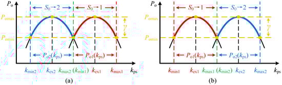
Figure 8.
Implementation of P-k curve interconnection for dual reconfiguration modes: (a) kmin2 < kmax2 = kmin1 < kmax1; and (b) kmin1 < kmax1 = kmin2 < kmax2.
- Case 1: kmin2 < kmax2 = kmin1 < kmax1 (Po1(kps) right, Po2(kps) left)
- Case 2: kmin1 < kmax1 = kmin2 < kmax2 (Po1(kps) left, Po2(kps) right)
Using Case 1 (Figure 8a) as the design basis yields the constraint:
Substituting (10), (16), and (17) into (18) establishes the mathematical relationships among six critical coupling coefficients:
where β represents the coupling variation multiple, and .
Equation (19) demonstrates that these relationships are uniquely determined by γ. Since kmax2 = kmin1, the extrema (kex1 and kex2) of both modes are interrelated:
Further substitution of (10) and (16) into (20) yields key design parameters:
Combining (2), (3), and (21) derives the remaining compensation components:
The input impedance and phase angle under Modes I/II are then derived by substituting (10) and (16) into (8) and (14) via (20)–(21):
Equation (23) indicates that Zin1, Zin2, θin1, and θin2 exhibit identical trends versus kps. Moreover, (19) constrains both phase angles to [arctan(1/β), arctan(β)].
For Case 2 (Figure 8b), constraints (18) and (19) remain valid, but (21) is modified to:
Comparative analysis of (21) and (24) reveals that under identical parameters (Ls, Ro, β, ω, kmax—where kmax = kmax1 in Case 1 and kmax = kmax2 in Case 2), the primary impedance coefficient α satisfies:
with α2 > α1.
To isolate α’s influence, Figure 9 plots Po vs. kps using Mode II’s power Equation (15) (a function of α) with Lp = 80 μH, Ls = 70 μH, f = 85 kHz, Ro = 10 Ω, UD = 100 V. The key observations are as follows:
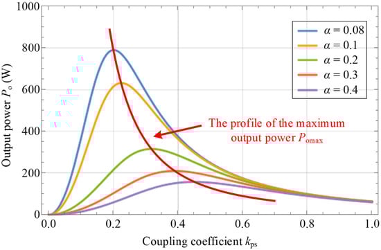
Figure 9.
Output power vs. coupling coefficient under varied impedance ratios.
- Power transmission decreases with increasing α at any kps.
- Detuning compensation achieves power stability by curtailing the maximum power capability.
- Higher α necessitates larger input voltage for equivalent power, increasing the component stress, volume, cost, and compromising reliability.
Thus, minimizing the input voltage requires minimizing α. Equation (25) confirms Case 1 (α1) as the optimal design (Figure 8a).
Equations (19)–(23) complete the circuit parameter design, enabling interconnected P-k curves for both modes. The subsequent section details the modal switching mechanism that ensures continuous complementary power delivery across the target coupling range.
4.2. Mode Switching Strategy
Based on the design configuration shown in Figure 8a, the relay S0 should initially engage Position 1 (detuned S-LCC topology) when the AUV is perfectly aligned. During rotational, axial, or air-gap misalignment, the S-LCC topology may fail to sustain stable power output (falling below the minimum allowable power Pomin). At this threshold, S0 switches to Position 2 (detuned S-S topology) to maintain stable power transmission. If misalignment further increases and the S-S topology’s output drops below Pomin, the AUV is deemed to be outside the preset operational range (kps < kmin2 or kps > kmax1). The WPT system then enters a quiescent state, suspending power transfer. This mode switching strategy is detailed in Figure 10.
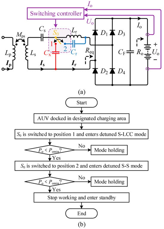
Figure 10.
(a) Control diagram of mode switching. (b) Flowchart of the dual reconfiguration mode switching.
Notably, the relay resides on the secondary side, enabling direct estimation of output power Po from battery voltage Uo and current Io measurements. This eliminates the need for primary–secondary communication. The strategy necessitates a constant load resistance Ro to ensure accurate Po estimation. To prevent false triggering during startup transients, the sampling module activates after a deliberate delay of tens of milliseconds. This brief postponement avoids misinterpretation of the initial current surge while negligibly impacting the AUV charging performance.
5. Experimental Validation
5.1. Experimental Prototype
To validate the effectiveness of the proposed reconfigurable WPT system, a 1.2 kW experimental prototype for AUV wireless charging was constructed, as shown in Figure 11, with the parameters detailed in Table 2. Critical adaptations for underwater operation include a pressurized waterproof enclosure (Figure 11b) housing CAD-DD coils wound with ferrite–nanocrystalline hybrid magnetic cores (Figure 11c), tested under simulated seawater conditions in water tanks. Secondary-side lightweighting was achieved through surface-mount capacitor implementation (Figure 11d), with the measured compensation parameters deviating ≤ 1.2% from the theoretical values—well within acceptable tolerance. The operational coupling ranges, calculated from (19) with the initial parameters in Table 1, were experimentally confirmed as [0.1533, 0.2415] for Mode I (detuned S-LCC topology with S0 at Position 1) and [0.2415, 0.3803] for Mode II (detuned S-S topology with S0 at Position 2), demonstrating the contiguous coupling range design principle. The experimental setup employed an ITECH IT6534D DC source at the transmitter and an ITECH IT8817B electronic load at the receiver, with the performance metrics monitored using a Tektronix MDO3054 oscilloscope and Yokogawa PX8000 power analyzer to characterize the misalignment tolerance. System stability was verified via 120 min continuous operation. Infrared thermography (Figure 12) showed key components reaching thermal equilibrium below 50 °C without operational anomalies.
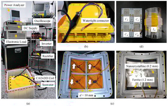
Figure 11.
Experimental prototype: (a) overall setup; (b) waterproof and compressive shell; (c) coil structure; and (d) compensation component.
Table 2.
Parameters of experimental prototype.
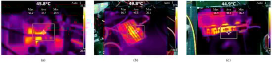
Figure 12.
Infrared thermal imaging diagrams of key components (at the 120 min): (a) inverter; (b) Cp; and (c) rectifier.
5.2. Experimental Results
Figure 13 presents the calculation and experimental results for the output power and system efficiency under rotational, axial, and air-gap misalignments of the AUV. Given the system’s operating frequency (85 kHz) is below 100 kHz, the eddy current losses induced by the seawater environment are negligible [31], resulting in close alignment between the experimental data and the theoretical predictions. Combining the misalignment characteristics in Figure 5a,c with the experimental results in Figure 13a,c, the rotational and air-gap misalignments maintain coupling coefficients above kmin1 even at the maximum offsets (dθ = 30°, dz = 50 mm). Output power remains at 1155.15 W and 1150.26 W, respectively, under these conditions, confirming that Mode I (detuned S-LCC topology with S0 at Position 1) suffices without requiring topology switching.
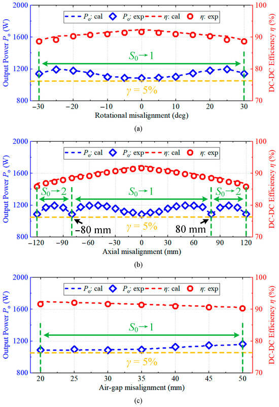
Figure 13.
Calculation and experimental results of output power and DC–DC efficiency with misalignments: (a) rotational misalignment; (b) axial misalignment; and (c) air-gap misalignment.
For axial misalignment, Figure 13b demonstrates stable power delivery in Mode I within dx ≤ 80 mm. Beyond this threshold (dx > 80 mm), S0 switches to Position 2 (detuned S-S topology) to maintain stable power. At the maximum tested axial offset (dx = 120 mm), the output power ranges between 1088.24 W and 1198.51 W. Based on the power fluctuation definition in (17), the variations remain within the designed 5% limit, validating the stable power transmission across wide misalignment ranges. System efficiency exceeds 85% across all the misalignment scenarios, including the most severe case at dx = 120 mm, peaking at 91.56% under perfect alignment. At the critical switching point (dx = 80 mm), both the output power and efficiency transition smoothly between topologies without abrupt jumps, verifying the effectiveness of the proposed parameter design. The power loss distributions at efficiency extremes (Figure 14) across six components—inverter, primary compensators, transmit coil, receiver coil, secondary compensators, and rectifier—reveal magnetic coupler losses (transmit and receiver coils) as the dominant contributor at >30% of the total loss. The secondary compensators emerge as the secondary loss source, exceeding the semiconductor switching losses.
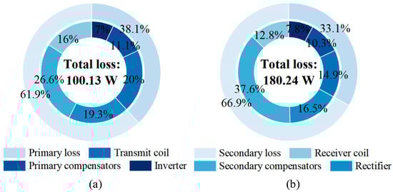
Figure 14.
Power loss distributions: (a) S0→1, dx = 0; and (b) S0→2, dx = 120 mm.
Figure 15 displays the steady-state waveforms of the inverter voltage Uab/current Ip and rectifier voltage Ucd/current Is under four conditions: rated operation, 80 mm/120 mm axial offsets, and full AUV detachment. Analysis confirms ZVS in the primary MOSFETs and sustained zero phase angle (ZPA) output on the secondary side across all the cases, ensuring efficient power transfer. As derived from (23), the input impedance phase angle increases from 29.68° to 36.12° with growing misalignment severity, aligning with theoretical predictions. During full detachment (Mps→0), Ip rises moderately without an exponential surge, maintaining system stability as anticipated. However, the elevated current generates strong magnetic fields that may disrupt AUV electronics, necessitating a protection circuit to halt inverter operation. These results demonstrate robust power delivery from alignment through extreme misalignment to detachment, while highlighting critical safety protocols for practical deployment.
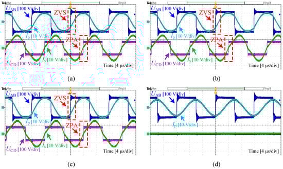
Figure 15.
Experimental waveforms: (a) S0→1, dx = 0; (b) S0→1, dx = 80 mm; (c) S0→2, dx = 120 mm; and (d) Mps→0.
5.3. Comprehensive Comparison with Previous Work
The methodology proposed in this work aims to address the issue of abrupt output power decline in AUVs when subjected to extensive, multi-dimensional misalignment offsets, thereby supplementing the limitations identified in prior research. To comprehensively demonstrate the superiority of the proposed reconfigurable WPT system, its performance metrics were meticulously compared against other methods reported in the literature over the past three years, with the detailed results presented in Table 3. It should be specifically noted that AUVs are typically equipped with docking interfaces during practical operation. Consequently, the offset ranges specified for the rotational and air-gap dimensions in this study (±30° for rotation, 20 mm to 50 mm for air gap) were determined based on the actual docking misalignment tolerances of AUVs. As illustrated in Figure 13, these specified ranges do not represent the maximum misalignment limits achievable by the proposed method.
Table 3.
Comparison with existing methods.
The comparative results in Table 3 clearly demonstrate that the proposed method simultaneously accommodates misalignment in all three dimensions—thereby endowing AUVs with significantly enhanced adaptability when operating in complex underwater environments. Furthermore, when confronted with extensive, multi-dimensional misalignment offsets, the proposed method exhibits notably smaller output fluctuations, thereby enabling more stable power transmission to the AUV.
6. Conclusions
To address the power instability in AUVs during multi-dimensional misalignment, this study developed a reconfigurable wireless charging system using CAD-DD coils with hybrid stacked ferrite–nanocrystalline cores. A reconfigurable detuned S-LCC/S compensation topology synergizes with these optimized lightweight coils, enabling single-frequency switching between S-LCC and S-S modes to sustain stable power across wide coupling variations. System design principles incorporating detuned compensation mechanisms were established. A 1.2 kW prototype validated the approach, maintaining ≤5% power fluctuation under ±30° rotation, ±120 mm axial, and 20–50 mm air-gap changes while achieving 85–91.56% efficiency. This system demonstrates superior misalignment tolerance and minimized output fluctuation versus existing methods.
Author Contributions
Conceptualization, Y.L. (Yonglu Liu) and M.X.; methodology, Y.L. (Yonglu Liu) and M.X.; software, Q.Z.; validation, Y.L. (Yonglu Liu) and Q.Z.; formal analysis, Y.L. (Yonglu Liu); investigation, M.X.; resources, Y.L. (Yu Lan) and Q.Z.; data curation, F.Y. and Y.L. (Yu Lan); writing—original draft preparation, Y.L. (Yonglu Liu); writing—review and editing, M.X. and K.S.; visualization, F.Y. and Y.L. (Yu Lan); supervision, K.S.; project administration, K.S. and J.J.; funding acquisition, K.S. and J.J. All authors have read and agreed to the published version of the manuscript.
Funding
This work was supported in part by Hainan Provincial Science and Technology Project under Grant 2021CXLH0001 and in part by the National Natural Science Foundation of China under Grants 52277006 and 52377004.
Data Availability Statement
The original contributions presented in this study are included in the article. Further inquiries can be directed to the corresponding author.
Acknowledgments
The authors gratefully acknowledge the financial and institutional support from the Department of Science and Technology of Hainan Province and the National Natural Science Foundation of China (NSFC), which played a critical role in enabling this research. Special thanks are extended to Harbin Electric Marine Intelligent Equipment Co., Ltd. for providing experimental facilities that constituted essential resources for this study and significantly contributed to the smooth implementation of the project.
Conflicts of Interest
The authors declare no conflicts of interest.
References
- Jawhar, I.; Mohamed, N.; Al-Jaroodi, J.; Zhang, S. An architecture for using autonomous underwater vehicles in wireless sensor networks for underwater pipeline monitoring. IEEE Trans. Ind. Inform. 2019, 15, 1329–1340. [Google Scholar] [CrossRef]
- Abou Houran, M.; Yang, X.; Chen, W. Magnetically Coupled Resonance WPT: Review of Compensation Topologies, Resonator Structures with Misalignment, and EMI Diagnostics. Electronics 2018, 7, 296. [Google Scholar] [CrossRef]
- Yu, L.; Sun, H.; Su, S.; Tang, H.; Sun, H.; Zhang, X. Review of Crucial Problems of Underwater Wireless Power Transmission. Electronics 2023, 12, 163. [Google Scholar] [CrossRef]
- Carreras, M.; Hernández, J.D.; Vidal, E.; Palomeras, N.; Ribas, D.; Ridao, P. Sparus II AUV—A hovering vehicle for seabed inspection. IEEE J. Ocean. Eng. 2018, 43, 344–355. [Google Scholar] [CrossRef]
- Song, K.; Lan, Y.; Zhang, X.; Jiang, J.; Sun, C.; Yang, G.; Yang, F.; Lan, H. A Review on Interoperability of Wireless Charging Systems for Electric Vehicles. Energies 2023, 16, 1653. [Google Scholar] [CrossRef]
- Yang, F.; Jiang, J.; Sun, C.; He, A.; Chen, W.; Lan, Y.; Song, K. Efficiency Improvement of Magnetic Coupler with Nanocrystalline Alloy Film for UAV Wireless Charging System with a Carbon Fiber Fuselage. Energies 2022, 15, 8363. [Google Scholar] [CrossRef]
- Lan, Y.; Jiang, J.; Yang, F.; Song, K.; Fan, F.; Sun, C.; Yang, G.; Zhang, B.; Lan, H. Research on Impedance Boundary and Tolerance Zone for Improving Wireless Charging Interoperability Evaluation of Electric Vehicles. IEEE Trans. Power Electron. 2024, 39, 12035–12040. [Google Scholar] [CrossRef]
- Liu, C.; Jiang, C.; Song, J.; Chau, K.T. An Effective Sandwiched Wireless Power Transfer System for Charging Implantable Cardiac Pacemaker. IEEE Trans. Ind. Electron. 2019, 66, 4108–4117. [Google Scholar] [CrossRef]
- Qiao, K.; Rong, E.; Sun, P.; Zhang, X.; Sun, J. Design of LCC-P Constant Current Topology Parameters for AUV Wireless Power Transfer. Energies 2022, 15, 5249. [Google Scholar] [CrossRef]
- Luo, T.; Zhang, S. Design of Underwater Wireless Power Transmission System Based on Inductive Coupling. J. Mar. Sci. Eng. 2023, 11, 1699. [Google Scholar] [CrossRef]
- Xiong, M.; Liu, Y.; Yang, F.; Lan, Y.; Zhang, Q.; Jiang, J.; Song, K. A Multidimensional Misalignment-Tolerant Wireless Power Transfer System Based on Coaxial Split Solenoid Coil for AUV Charging Applications. In Proceedings of the 2025 IEEE International Conference on Industrial Technology (ICIT), Wuhan, China, 26–28 March 2025; pp. 1–6. [Google Scholar]
- Zhang, B.; Yang, F.; Zhou, J.; Wang, Y.; Jiang, C.Q.; Mo, L.; Fan, Y.; Zhu, Y.; Zhang, C.; Lu, Y. A High-Compatibility Wireless Power Transfer System for Autonomous Underwater Vehicles Based on Reconfigurable Magnetic Couplers. IEEE Trans. Ind. Appl. 2025, 61, 3457–3467. [Google Scholar] [CrossRef]
- Gong, Z.-W.; Li, J.-G.; Tong, X.-Q. Misalignment-Tolerant Series Hybrid with Active Adjustable Constant Current and Constant Voltage Output Wireless Charging System. Energies 2021, 14, 7594. [Google Scholar] [CrossRef]
- Zhang, Q.; Liu, Y.; Yang, F.; Lan, Y.; Xiong, M.; Jiang, J.; Song, K. Design of Magnetic Coupler for a 3 km Underwater AUV Wireless Charging System. In Proceedings of the 2025 IEEE International Conference on Industrial Technology (ICIT), Wuhan, China, 26–28 March 2025; pp. 1–4. [Google Scholar]
- Xia, C.; Wang, W.; Ren, S.; Wu, X.; Sun, Y. Robust Control for Inductively Coupled Power Transfer Systems with Coil Misalignment. IEEE Trans. Power Electron. 2018, 33, 8110–8122. [Google Scholar] [CrossRef]
- Xia, T.; Zhang, X.; Zhu, Z.; Yu, H.; Li, H. An Adaptive Control Strategy for Underwater Wireless Charging System Output Power with an Arc-Shaped Magnetic Core Structure. J. Mar. Sci. Eng. 2023, 11, 294. [Google Scholar] [CrossRef]
- Chen, S.; Li, H.; Tang, Y. Extending the Operating Region of Inductive Power Transfer Systems through Dual-Side Cooperative Control. IEEE Trans. Ind. Electron. 2020, 67, 9302–9312. [Google Scholar] [CrossRef]
- Yan, Z.; Song, B.; Zhang, Y.; Zhang, K.; Mao, Z.; Hu, Y. A Rotation-Free Wireless Power Transfer System with Stable Output Power and Efficiency for Autonomous Underwater Vehicles. IEEE Trans. Power Electron. 2019, 34, 4005–4008. [Google Scholar] [CrossRef]
- Yan, Z.; Wu, M.; Zhao, C.; Hu, Q.; Zhu, L.; Qiao, L.; Wang, L. Free-Rotation Wireless Power Transfer System Based on Composite Anti-Misalignment Method for AUVs. IEEE Trans. Power Electron. 2023, 38, 4262–4266. [Google Scholar] [CrossRef]
- Wu, S.; Cai, C.; Wang, A.; Qin, Z.; Yang, S. Design and Implementation of a Uniform Power and Stable Efficiency Wireless Charging System for Autonomous Underwater Vehicles. IEEE Trans. Ind. Electron. 2023, 70, 5674–5684. [Google Scholar] [CrossRef]
- Zhao, L.; Thrimawithana, D.J.; Madawala, U.K. Hybrid Bidirectional Wireless EV Charging System Tolerant to Pad Misalignment. IEEE Trans. Ind. Electron. 2017, 64, 7079–7086. [Google Scholar] [CrossRef]
- Chen, Y.; Yang, B.; Zhou, X.; Li, Q.; He, Z.; Mai, R.; Lai, J.S. A Hybrid Inductive Power Transfer System with Misalignment Tolerance Using Quadruple-D Quadrature Pads. IEEE Trans. Power Electron. 2020, 35, 6039–6049. [Google Scholar] [CrossRef]
- Yan, K.; Dang, R.; Feng, X.; Wang, W. A New Magnetic Coupler with High Misalignment Tolerance and Inherent Constant Current–Constant Voltage for Underground Wireless Charging. Energies 2024, 17, 5130. [Google Scholar] [CrossRef]
- Chen, Y.; Yang, B.; Li, Q.; Feng, H.; Zhou, X.; He, Z.; Mai, R. Reconfigurable Topology for IPT System Maintaining Stable Transmission Power over Large Coupling Variation. IEEE Trans. Power Electron. 2020, 35, 4915–4924. [Google Scholar] [CrossRef]
- Zhang, Y.; Pan, W.; Wang, H.; Shen, Z.; Wu, Y.; Dong, J.; Mao, X. Misalignment-Tolerant Dual-Transmitter Electric Vehicle Wireless Charging System with Reconfigurable Topologies. IEEE Trans. Power Electron. 2022, 37, 8816–8819. [Google Scholar] [CrossRef]
- Chen, C.; Jiang, C.Q.; Ma, T.; Wang, X.; Fan, Y.; Xiang, J. Misalignment Tolerance Extension for Inductive Power Transfer System by Utilizing Slight Frequency-Detuned Compensation. IEEE Trans. Transp. Electrif. 2024, 10, 9748–9760. [Google Scholar] [CrossRef]
- Liu, Z.; Su, M.; Zhu, Q.; Zhao, L.; Hu, A.P. A Dual Frequency Tuning Method for Improved Coupling Tolerance of Wireless Power Transfer System. IEEE Trans. Power Electron. 2021, 36, 7360–7365. [Google Scholar] [CrossRef]
- Casaucao, I.; Linares, A.; Triviño, A. Coils Optimisation to Avoid Parasitic Capacitance Effects in an Inductive Wireless Charger for Underwater Vehicles. Electronics 2025, 14, 654. [Google Scholar] [CrossRef]
- Chen, C.; Jiang, C.Q.; Wang, X.; Mo, L.; Guo, W.; Ren, S. Terrace-Shaped Core Design Method for Inductive Power Transfer System Considering Uniform Magnetic Flux Distribution. IEEE Trans. Ind. Electron. 2025; in press. [Google Scholar] [CrossRef]
- Wang, Y.; Jiang, C.Q.; Chen, C.; Wang, X.; Li, X.; Long, T. Design and Analysis of Inductive Power Transfer System Using Nanocrystalline Flake Ribbon Core. IEEE J. Emerg. Sel. Top. Power Electron. 2024, 12, 3334–3347. [Google Scholar] [CrossRef]
- Kan, T.; Mai, R.; Mercier, P.P.; Mi, C.C. Design and Analysis of a Three-Phase Wireless Charging System for Lightweight Autonomous Underwater Vehicles. IEEE Trans. Power Electron. 2018, 33, 6622–6632. [Google Scholar] [CrossRef]
- Mostafa, A.; Wang, Y.; Tangirala, S.; Zhang, H.; Lu, F. A 5 kW Hull-Compatible Inductive Charging System with 360° Folded Spatial Unipolar Coupler for Autonomous Underwater Vehicles (AUVs). IEEE Trans. Ind. Appl. 2023, 59, 7001–7012. [Google Scholar] [CrossRef]
- Chen, Z.; Zhang, X.; Xu, F.; Yang, Q.; Li, M.; Deng, X. Novel Designs of Magnetic Coupled Structure with 360° Rotation Misalignment Tolerance for AUVs’ Wireless Charging System. IEEE Trans. Power Electron. 2024, 39, 15403–15408. [Google Scholar] [CrossRef]
- Tang, H.; Liu, C.; Pan, W.; Rao, P.; Zhuang, Y.; Chen, X.; Zhang, Y. A Self-Adaptive Dual-Channel LCC-S Detuned Topology for Misalignment Tolerance in AUV Wireless Power Transfer Systems. IEEE Trans. Power Electron. 2025, 40, 4630–4639. [Google Scholar] [CrossRef]
Disclaimer/Publisher’s Note: The statements, opinions and data contained in all publications are solely those of the individual author(s) and contributor(s) and not of MDPI and/or the editor(s). MDPI and/or the editor(s) disclaim responsibility for any injury to people or property resulting from any ideas, methods, instructions or products referred to in the content. |
© 2025 by the authors. Licensee MDPI, Basel, Switzerland. This article is an open access article distributed under the terms and conditions of the Creative Commons Attribution (CC BY) license (https://creativecommons.org/licenses/by/4.0/).