Article

Transmitting Double-D Coil to Wirelessly Recharge the Battery of a Drone with a Receiving Coil Integrated in the Landing Gear

by
Wassim Boumerdassi
1,
Tommaso Campi
2,
Silvano Cruciani
3,
Francesca Maradei
2 and
Mauro Feliziani
1,*
1
Department of Industrial and Information Engineering and Economics, University of L’Aquila, 67100 L’Aquila, Italy
2
Department of Industrial and Information Engineering, Sapienza University of Rome, 00184 Rome, Italy
3
Department of Industrial Engineering, Tor Vergata University of Rome, 00133 Rome, Italy
*
Author to whom correspondence should be addressed.
Energies 2025, 18(10), 2587; https://doi.org/10.3390/en18102587
Submission received: 4 April 2025 / Revised: 28 April 2025 / Accepted: 14 May 2025 / Published: 16 May 2025
(This article belongs to the Special Issue Advances in Wireless Power Transfer Technologies and Applications)

Abstract

:
The aim of this work is the design of a 200 W transmitting coil for a high-power wireless power transfer (WPT) system based on magnetic resonant coupling (MRC) to charge the battery of a drone in 1 h equipped with a WPT receiving coil integrated into the landing gear. This innovative solution is based on the use of the landing gear as the receiving coil, thereby obviating the need for an additional component (e.g., separate receiving coil). The proposed landing gear is fabricated from aluminum, to reduce weight, and to improve mechanical robustness and electrical performance. Consequently, the design reduces overall weight and system complexity while minimizing potential destabilization of the drone’s flight dynamics. However, a specific design of the primary coil is required to ensure high efficiency even in case of an inaccurate landing of the drone on a ground pad. To this aim, a double-D configuration is here proposed and optimized for the transmitting coil, while a double coil receiver in combination with a charge controller that uses a maximum power point tracking (MPPT) algorithm is integrated into the landing gear. The results obtained from the simulations demonstrate that the proposed WPT system has excellent electrical efficiency and very high tolerance to coil misalignment in terms of the coupling coefficient due to imprecise landing. The transmission efficiency of the final test prototype can reach 95% with a coupling coefficient of k = 0.16, and it can drop to a minimum of 85% when misalignment occurs resulting in k = 0.06.

1. Introduction

The use of electric drones is growing very rapidly in many fields of application for surveillance, monitoring and couriers. Currently, the flight time of small- to medium-sized commercial drones is around 20–40 min [1,2]. This limited time can be one of the major drawbacks, especially for applications where the drone (or a fleet of drones) would need to be operational for a long or even continuous time. Increasing the capacity of the onboard electric batteries is not a viable solution to increase flight time due to the corresponding increase in weight, which is often not compatible with flight operations. On the contrary, an interesting solution to extend the drone’s autonomy is a rapid charging process that does not require any human intervention. In this way, the drone can become energy autonomous and can therefore operate in remote contexts without human assistance.
There are several techniques used in the past to supply electricity to a drone such as the automated battery swapping in suitably equipped stations or using galvanic sliding contacts which allow the battery to be recharged in the presence of suitable electrical sources, or through wireless charging [3,4,5,6,7,8,9,10]. Currently, wireless power transfer (WPT) is the most attractive technology for its convenience and versatility in consumer electronics, making the charging of devices, such as smartphones and other electronic devices, more convenient and without cables. This technology is under study in various sectors, including automotive industry, healthcare, and indoor applications [11,12,13]. There are different WPT technologies based on inductive power transmission (IPT), magneto resonant coupling (MRC), capacitive coupling, microwave (MW) coupling, laser coupling, etc., [14]. The focus here is on MRC-WPT technology [15]. There are several papers, patents and commercial products (announced or just released on the market) to apply the MRC-WPT technology to recharge the battery of a drone [6,7,8,9,10]. However, many of these solutions can lead to some drawbacks for drone performance, such as additional cost and weight, obstruction of vision for onboard cameras, degradation of aerodynamics, etc. Therefore, in the following sections, we will consider the solutions that do not alter the traditional structure of the drone, i.e., when no additional elements are added for the receiving coil of the wireless charging system on board the drone. In previous work, a straightforward yet effective solution for the receiving coil was proposed. It consists of the design of a drone landing gear, which has the dual function of structural support and receiving coil of the wireless charging system [16]. Furthermore, to address potential EMI issues affecting the electronic components onboard the drone, a comprehensive evaluation on comparable systems operating at the same frequency is presented in [17]. These assessments have demonstrated that the magnetic field generated by the WPT system does not alter the operational function of the drone. In the present work, the focus is on the design and optimization of a transmitting units, and on the increment of the performance for efficiently recharging the battery of a drone using an autonomous charge controller when the landing gear is used as receiving coil. To this aim, an innovative configuration based on the double-D (DD) coil [18,19,20] is presented in combination with an optimized electronic control system.

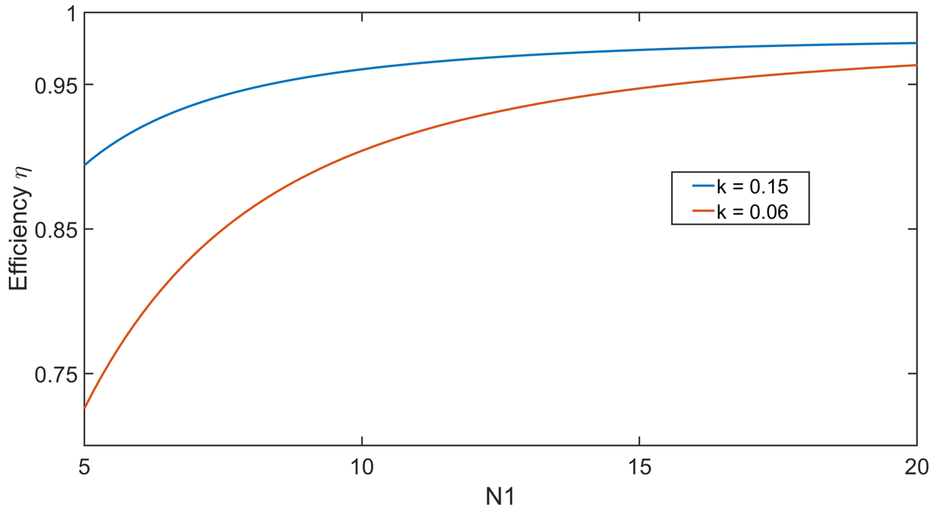
2. MCR-WPT Circuit Model and Performances

The equivalent circuit of the high-frequency section of an MRC-WPT system is shown in Figure 1. To improve the WPT performance, the system operates in resonance, which is obtained by an additional circuit known as a compensation network. At resonance, the excitation can be modeled by a voltage source VS with a series resistance RS and the load by a simple resistance RL. The series–series (SS) compensation network [21] is adopted due to its inherent simplicity, which is particularly well-suited for the relatively low current levels and minimal misalignment encountered in this application. It also permits the minimization of the number of lumped components, and thus the weight, which is of paramount importance, mainly on the onboard side. Furthermore, it was selected due to its higher efficiency when using a secondary coil with a limited number of turns. This compensation is based on capacitors C1 and C2 connected in series to Tx and Rx coils, depicted in Figure 1 by the equivalent series resistances R1 and R2 and by the self- and mutual-inductances L1, L2 and M. In the proposed solution, the system resonates at the frequency f0 = 300 kHz. The selection of a 300 kHz operating frequency is motivated by its alignment with the Qi wireless charging standard, ensuring compatibility with existing systems and thereby improving the efficiency of the power transfer process, mostly when the secondary coil is small and composed of a single turn. On the other hand, the increase in frequency will improve losses; however, thanks to the adequate design of the system (e.g., hollow aluminum pipe for the receiver), the overall performances are increased.
The values of C1 and C2 are obtained by:
C 1 = ( ω 0   2 L 1 ) 1
C 2 = ( ω 0   2 L 2 ) 1
being ω0 = 2πf0.
The efficiency η is defined as the ratio between the output real power P2 at port 2-2′ and the input real power P1 at port 1-1′ as:
η = P 2 P 1 = ω 0 M 2 1 + R 2 R 1 R 1 R 2 + R L + ω 0   2 M 2
The real power at the input port 1-1′ is given by:
P 1 = Re ( V 1 I 1 )
where * denotes the complex conjugate, and V1 is the voltage across such port. The real power at the output port 2-2′, with a voltage V2 across it, is given by:
P 2 = Re ( V 2 I 2 )
From the battery specification, it is possible to approximately calculate the average value of the equivalent DC resistance as RDC = Vbat/Ich, with Vbat being the battery voltage and Ich the charging current. Then, the load resistance RL can be expressed for traditional rectification as:
R L = π 2 8 R D C
In this case, the optimal value of the load resistance RLopt that maximizes the efficiency η is obtained from ∂η/∂RL = 0, and it is given by [10,22]:
R L o p t = ω 0 M R 2 R 1 + R 2 ω 0 M 2

3. WPT System Design

In the proposed application, the objective is to recharge the battery of a medium-sized drone (capable of carrying a 2–4 kg payload) within approximately one hour assuming a battery capacity of 9 Ah. The battery is assumed to have a nominal voltage Vbat = 22 V and a charging current Ich = 9 A, resulting in an equivalent resistive load RL = 3 Ω and a battery charging power of Pbat = 200 W.
Cost considerations have also been a key aspect of the system design. The simplicity of the SS compensation topology, combined with the integration of the secondary coil into existing drone components, contributes to a cost-effective design. This approach minimizes the number of additional parts, extra weight and manufacturing complexities, thereby reducing the overall production costs while ensuring high performance and reliability. In the following section, the design procedure of both receiving and transmitting coils is presented.

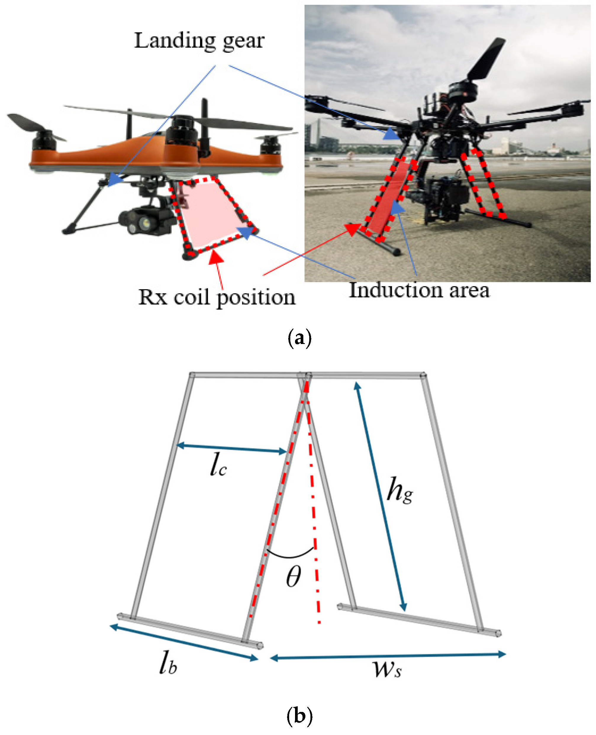
3.1. WPT Receiving Coil Design

As mentioned above, the receiving coil coincides physically with the landing gear. Thus, the shape and material of the landing gear must have adequate mechanical and electrical characteristics. In fact, the landing gear must guarantee mechanical resistance for the landing [23], and at the same time must be a good electrical conductor to act as a receiver for the WPT system. Therefore, the drone’s landing gear cannot be made of non-conductive materials such as plastic or composite materials as it would not respect the electrical features. For its realization, there are mainly two different solutions: to adopt a copper litz wire placed above the landing gear, or to replace the landing gear generally in plastic with an identical one but made up of aluminum. Using litz wire is much better for electrical performance as the AC resistance of the coil is very low, but it requires an additional component (i.e., litz wire coil) on board the drone, which results in extra weight, and this is not always allowed. Conversely, the use of an aluminum tube allows for seamless integration with the mechanical system and also reduces the number of additional receiver components to be placed on the drone. In this application, it is assumed that the receiving coil is made of a hollow aluminum tube with an external diameter of 5 mm and a thickness of 1 mm. Since it is a hollow tube, the skin effect is adequately kept under control and, given the high conductivity of the aluminum, the losses are very limited. The receiver coil forms a closed loop of rectangular shape for each landing skid. To improve the performance, we consider two receiving coils, one on the right leg and one on the left leg, as shown in Figure 2. In our solution, the two receiving coils are used one at a time, so only the one that has the highest coupling factor k with the transmitting coil is selected to operate. This allows for improved wireless charging, even for an imprecise landing. The loop area of each receiving coil is equal to hg × lc = 200 × 200 mm2; note that the length of the landing support edge lb = 250 mm with an orientation angle θ = 15° (see Figure 2b). The shape of the landing gear was optimized for capturing the maximum magnetic flux produced by the transmitting coil placed in the ground station. Due to the shape of the landing gear, the magnetic flux produced by the transmitting coil must be mostly horizontal to have a good coupling.
The values of the inductances of the two receiving coils are reported below in Table 1.

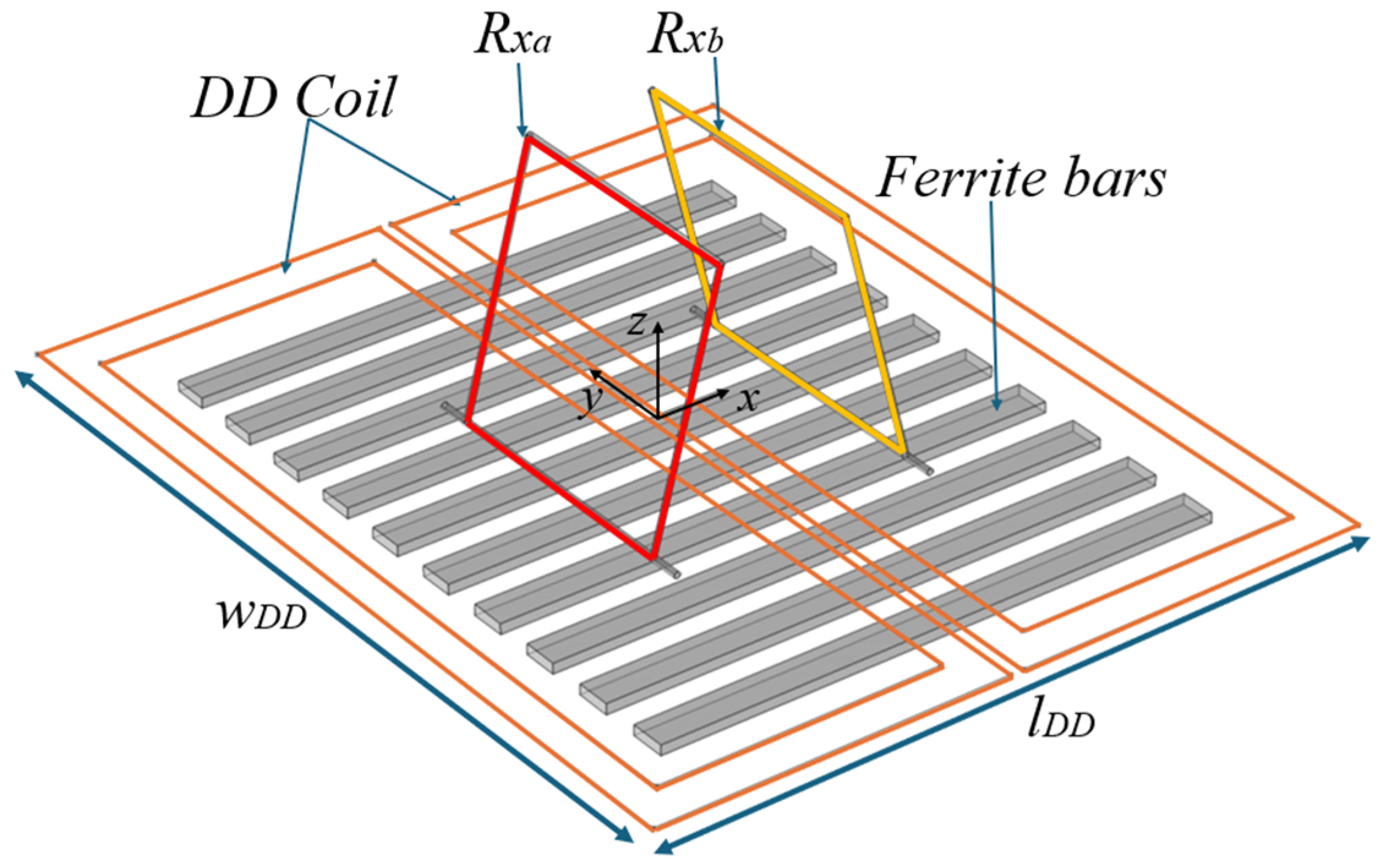
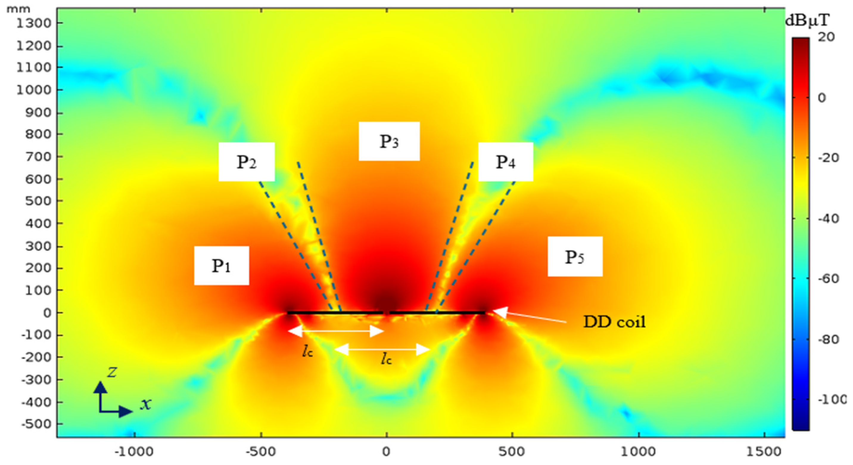
3.2. WPT Transmitting Coil Design

Given the requirement for a horizontal magnetic field, two main transmitter–coil configurations were considered: the solenoid and the planar double-D (DD) coil. Although the solenoid delivers a uniform field, it relies on a bulky ferrite core, making it less practical. In contrast, the DD coil widely adopted in EV wireless charging produces a uniform horizontal field whose flux lines remain optimally perpendicular to the secondary coil when it is oriented orthogonally to it, thereby ensuring the coupling. Consequently, this configuration enhances coupling efficiency and maximizes energy transfer in the WPT system. For these reasons, the DD configuration is adopted in this study as the transmitting coil, mounted on the ground pad where the drone lands. The primary coil has a DD configuration which is made by two rectangular identical coils connected in parallel, as shown in Figure 3. The size of the primary coil is strictly related to the precision of the landing system. Considering a drone equipped with a RTK GSP system, a precision of ±20 cm can be easily expected [23]. The considered DD coil adopted in this work has an external dimension of lDD = 760 mm and wDD = 600 mm.
To improve system performance and avoid flux dispersion, some ferrite bars (µr = 2000, σ = 1 × 10⁻⁶ S/m) with size 70 × 10 cm2 are each placed under the DD coil once. Since the drone’s autopilot generally guarantees a very high precision on the landing angle, we therefore assume a perfect orientation of the coils on the y-axis. The DD coil is made with copper litz wire composed of 840 insulated strands of AVG 41 wire to reduce skin and proximity effects in high-frequency coils, ensuring uniform current distribution and minimizing power losses. The considered litz wire has a per unit length (p.u.l) resistance equal to Rm = 5 mΩ/m at 300 kHz. A finite element analysis (FEA) is performed to extract the self and mutual inductances of the coils using Ohm’s law and also to calculate the behavior of the magnetic field [7].

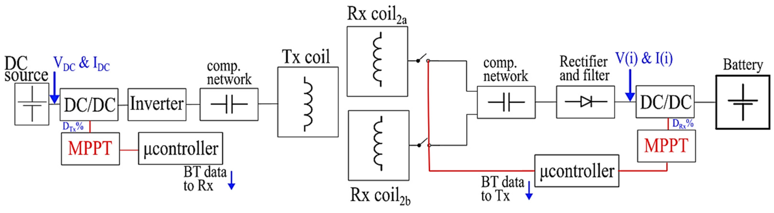
4. Electronic Design and Control System

The electronic block diagram of a typical MCR-WPT system is shown in Figure 4. The transmitter is installed in a ground pad and the receiver is on board the drone. The transmitter is fed by a DC bus and via an inverter that produces a high-frequency signal is connected to the transmitting coil which is inductively coupled with the receiving coil. On the receiving side, the coil is connected to the battery through a rectifier and an impedance converter. WPT efficiency is obtained by (2). As mentioned, the system is powered by a direct current (DC) source, which may be a battery, a fixed mains power supply, an autonomous renewable energy source (solar panels, wind turbines, etc.), or with an alternating current (AC) source that needs to be rectified. Subsequently, there is an electronic DC/DC voltage regulator capable of varying the input voltage value depending on the power required by the load (battery). Downstream of the regulator is a high-frequency inverter that converts the DC voltage into a square wave voltage at the working frequency f0 of the WPT system. The inverter is connected to a capacitor bank to impose resonance conditions, and to the transmitting coil. On the receiving side, the landing gear coils are connected to the capacitor bank for resonance conditions and then to the rectifier [24], which converts the voltage into direct current. The rectified voltage is connected to a DC/DC converter by a filter. Between the rectifier and the battery, a system is installed to monitor the voltage and charging current. This system is equipped with an interface capable of wirelessly communicating charge parameters to the base station.

4.1. Receiving Side Converter and Logic Control

The charging process begins by setting a low value duty-cycle for a low-power initial AC on the primary coil, which is necessary to calculate the voltage induced on the two-receiving coils. By measuring the induced voltage and knowing the applied current value, the mutual inductances between the transmitter and the two receiving coils are derived as
M a = Im V 2 a ω I 1 ;   M b = Im V 2 b ω I 1
where V2a and V2b are the induced voltages on each Rx coil and I1 is the Tx coil current. The coupling coefficients ka and kb are easily derived for each coil.
At this stage, the microcontroller switches to the receiver with the highest value (i.e., k = max(ka, kb)). Once established the receiving side coil and known its coupling factor k, the charging current Ich and the actual voltage state of the battery, the receiving-side converter adjusts the resistance seen at its input by varying the duty cycle. This adjustment allows the equivalent resistance to reach its optimal value by varying the output voltage keeping a constant power, ensuring the most efficient power transfer to the load according to (6).
The optimal load resistance RL_opt increases linearly with k, as shown in Figure 5. However, since RL_opt < RL, a direct connection would result in suboptimal performance. To address this, a boost converter, illustrated in Figure 6, can be used to match the effective resistance seen by the system to the optimal value.
The boost converter functions as an impedance transformation stage, adjusting the load resistance according to the conversion factor 1/(1 − DRx) where DRx is the duty cycle of the converter. By properly tuning DRx, the converter ensures that the system operates at the desired RL_opt, maximizing efficiency and performance. This approach is particularly beneficial in applications where maintaining the optimal load resistance is crucial for stability and energy transfer efficiency.
The resistance seen at the input port of the boost converter is given by:
R i n = V o u t I o u t 1 D R x 2
where Vout and Iout are the output of the step-up converter in Figure 6.
A parametric simulation was conducted to analyze the actual performance of the converter with a fixed duty cycle DRx = 80% (which is the optimal value for k = 0.14), assuming different values of the coupling factor, and the results are shown in Figure 7. As can be seen, the current ripple is fixed for an inductor of 20 μH, which is responsible for the ripple variation in the input resistance Rin. Meanwhile, the voltage ripple at the output is due to the capacitor of 40 μF.
For improved efficiency and autonomous operation, once the system is powered on, the receiver continuously monitors the received voltage V(i) and current I(i), which fluctuate due to variations in the charging process. By comparing the values of the current cycle “i” with those of the previous cycle “i − 1”, the system dynamically adjusts the duty cycle of the converter in real-time.
This adaptive control mechanism ensures that the effective load resistance remains at its optimal value, maximizing energy transfer efficiency. The continuous feedback loop allows the system to respond to variations in input conditions, maintaining stable and efficient performance throughout the charging process.
The flowchart in Figure 8 schematically illustrates this control strategy, showing how the duty cycle DRx is iteratively adjusted to achieve optimal efficiency. This real-time regulation enhances the system’s robustness and adaptability, eliminating the need for manual intervention.

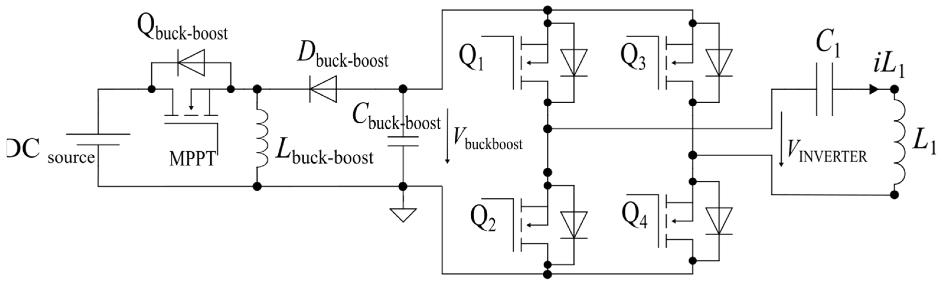
4.2. Transmitting Side Converter and Logic Control

The Tx voltage is adjusted using the DC/DC converter [25,26] present in the transmission chain to reach the optimum value of RL, according to the configuration shown in Figure 9. This adjustment is based on the value of battery voltage and input voltage at that specific moment. If the input DC voltage is a renewable source as a solar panel, a buck-boost converter is needed. A buck-boost converter is ideal for regulating the variable DC voltage from a solar panel, ensuring a stable output for any load. Since solar panel voltage fluctuates with sunlight conditions, a buck-boost converter can either step-up or step-down the voltage as needed. This flexibility makes it useful when the required output voltage falls between the panel’s minimum and maximum voltage range. Additionally, it improves power transfer efficiency and, when combined with MPPT, helps extract the maximum energy from the panel. The converting factor is: −DTx/(1 − DTx); therefore, when DTx < 0.5 it acts as a buck converter; instead for DTx > 0.5 as a boost converter.
A similar parametric simulation, as performed for the Rx side, was conducted for the Tx chain. Figure 10 illustrates the behavior of key parameters in the transmission stage, including the output voltage of the DC/DC converter, the output voltage of the inverter, and the Tx coil current.
In this simulation, the input DC voltage was varied while maintaining the duty cycle DTx fixed at 70%. This analysis provides insight into the system’s response to input voltage variations, helping to evaluate the stability and efficiency of power transfer under different operating conditions.
Understanding how the system reacts to these variations is particularly important for developing an optimal control strategy. By studying the relationship between input voltage, converter output and coil current, it becomes possible to refine the control logic, enabling dynamic adjustments that maximize power transfer efficiency. This approach ensures that the system can adapt to real-world conditions, improving robustness and maintaining optimal operation even in the presence of fluctuating supply voltages.
The control logic system has a dual function: managing the start/stop phases of charging and regulating the power supplied to the battery. To maximize power transfer, an MPPT algorithm (Figure 11), specifically the perturb and observe method (P&O), is implemented [27,28,29]. This algorithm periodically perturbs the operating point and observes the resulting power variation, adjusting the duty cycle accordingly to ensure optimal efficiency. The duty cycle variation is achieved using the successive approximation technique, which starts with a coarse initial estimate and iteratively updates the solution, progressively refining its accuracy. Each step builds upon the previous one, improving the result until the difference between two successive iterations is sufficiently small or the required voltage value is satisfied. It should be noted that the implemented system can easily control the charging procedure typically used for lithium batteries, mainly requiring a constant current charging phase followed by a final constant-voltage phase. The only additional required system is the cells balancing system.

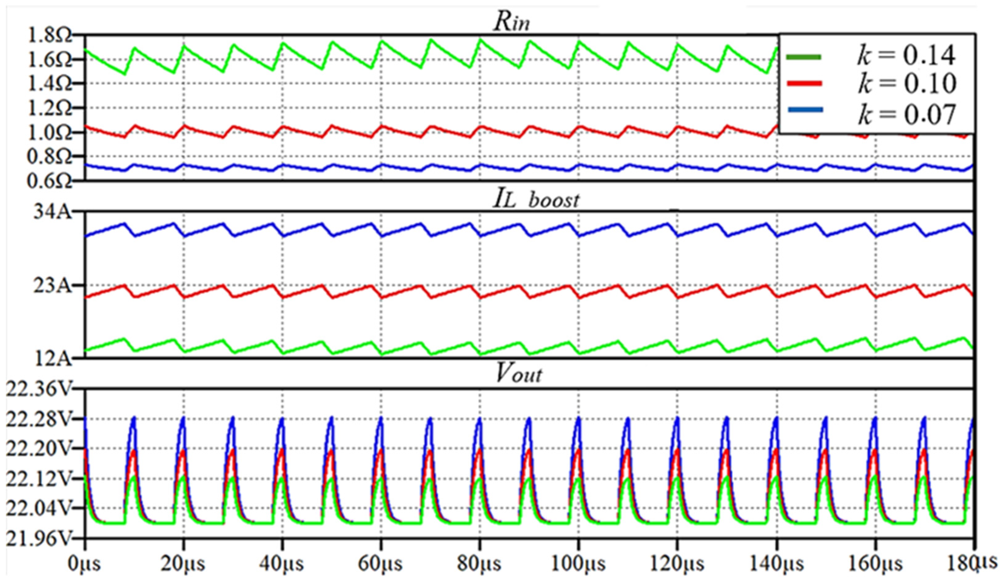
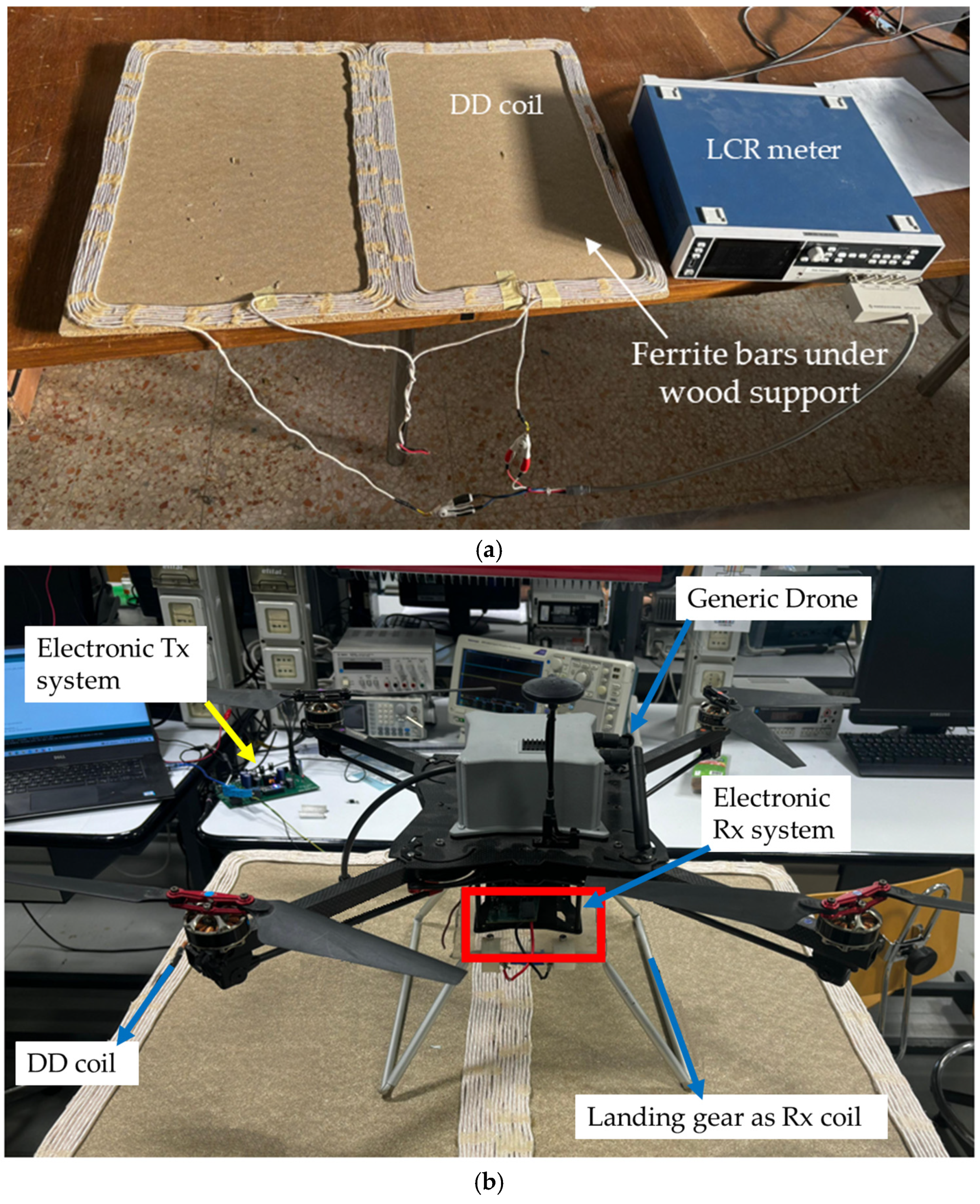
5. Numerical Simulation and Experimental Measurements Results

Numerical simulations and experimental measurements are complementary approaches. Simulations allow for the prediction of system behaviors, while experimental data validate and refine these models. Combining both methods enhances accuracy and optimizes practical outcomes. Firstly, a numerical simulation was performed to calculate the behavior of the magnetic field produced by the transmitting coil. For this analysis, the DD coil lays on xy plane and it is assumed made of a single turn. The calculated map of the horizontal component of the magnetic flux density, Bx, on the vertical plane xz at y = 0 is shown in Figure 12. As can be noted, there are three areas where a strong magnetic field can be obtained: zone P1, zone P3, and zone P5. The zones where the magnetic field is low are zones P2 and P4 which approximately coincide with the center of each rectangular coil. The separation lc between these two zones is equal to lDD/2. The proposed landing gear with two receiver coils is very convenient since it is sufficient for the landing gear leg separation ws to be different from lDD/2 to ensure that at least one Rx coil is in zone P1, P3 or P5. In our work, the length of the DD coil is lDD = 760 mm, while the leg spacing is ws = 200 mm.
A sensitivity analysis is performed on the influence of the primary coil turns number as shown in Figure 13 where the wireless power transfer efficiency versus N1 is reported for maximum and minimum coupling conditions evaluated firstly by numerical simulation (kmax = 0.15 and kmin = 0.06). As can be seen, the best performance is obtained in both cases for N1 = 8–12, with extremely high efficiency for good landing precision (ƞ > 93%) and still a very good efficiency in cases of maximum misalignment (ƞ = 77%). Any further increase in N1 brings no benefit to efficiency. In the following, N1 = 8 is assumed as the number of turns of each primary D coil.
Circuit parameters were experimentally measured using the Rohde and Schwarz LCX200 LCR meter (Munich, Germany) according to the measurement setup shown in Figure 14. The experimental setup, shown in Figure 14b, uses an oscilloscope and bench power supplies. A 48 V DC supply is used as the primary energy source, which is then converted to the operating frequency f0 via an inverter. This AC signal is conditioned through a bank of resonant capacitors to feed the primary coil. By measuring the induced voltage in the receiving coils and accurately controlling the applied current, the mutual inductances between the transmitter and the two receiving coils are derived from (7). The derivation from measurements of the coupling factors ka and kb between the transmitter and the two receiving coils has been performed by neglecting the coupling between the two receiving coils a and b. This is reasonable since the Rx coil which is not used for power transfer is in an open condition, and therefore does not alter the magnetic field behavior. The coupling factor was calculated considering the coils aligned or translated on both x and y axes. This comprehensive setup ensures the precise calibration and repeatability of the experimental results.
The setup includes the ferrite bars under the wood support; these values obtained in terms of coupling factor k are presented in Table 1. In this context, eddy currents and joule effects considering the material properties losses are also considered. Based on experimental measurements, the primary coil resistance R1 = 300 mΩ leads to a power dissipation of 24.3 W, while the secondary coil resistance R2 = 20 mΩ results in a dissipation of about 1.6 W. This provides a preliminary estimation of the thermal behavior during a typical charging cycle. However, given the physical size and surface area of the coils, such levels of power dissipation can be handled without significant temperature rise, thus avoiding the need for active cooling systems [29].
As can be seen, the use of the double receiving coil allows a coupling factor kmin > 0.05 to be obtained in any position. The coils with the best coupling for each position are in bold. Selection of the best-matching coil can be performed by a measurement of the input impedance after the coil has landed, as described for the primary side in [10].
Table 1. DD WPT lumped element.
MisalignmentMeasurements
x
(cm)
y
(cm)
L1
(µH)
L2a
(µH)
L2b
(µH)
kakb
−1002091.091.070.1580.045
000.1290.137
2500.0640.061
−10200.1130.017
10200.0380.062
20200.0540.006
The efficiency versus the coupling coefficient is shown in Figure 15 considering a fixed load RL = 3 Ω and with the optimal load that permits the efficiency to be maximized, considering the SS compensation. As observed, it is crucial to ensure that the system operates under optimal load conditions to maximize efficiency. Therefore, in the previous section, an electronic architecture and control system designed to achieve maximum efficiency, regardless of the landing position, has been presented. The system performances in terms of efficiency for different landing position is also reported in Table 2, in which the activated receiving coil for each position is also highlighted.

6. Conclusions

An innovative architecture was presented for the transmitting coil of a WPT system that recharges the battery of a drone equipped with a landing gear used as a receiving coil. This solution allows the magnetic coupling to be maximized without adding weight and additional components on board the drone. A design procedure of the transmitting coil based on double-D configuration is presented. The receiver, integrated in the landing gear of the drone, is composed by two separate coils. The results prove that the proposed solution is very reliable, electrically efficient, low-cost and mechanically robust. High levels of electrical efficiency are achieved with a high tolerance for imperfect landing.

Author Contributions

Conceptualization, F.M. and M.F.; Methodology, W.B. and T.C.; Software, W.B., T.C. and S.C.; Validation, W.B. and T.C.; Supervision, F.M. and M.F. All authors have read and agreed to the published version of the manuscript.

Funding

This research received no external funding.

Data Availability Statement

The original contributions presented in the study are included in the article, further inquiries can be directed to the corresponding author.

Conflicts of Interest

The authors declare no conflict of interest.

References

  1. Sujit, P.B.; Ghose, D. Search using multiple UAVS with flight time constraints. IEEE Trans. Aerosp. Electron. Syst. 2004, 40, 491–509. [Google Scholar] [CrossRef]
  2. Lee, B.; Kwon, S.; Park, P.; Kim, K. Active Power Management System for an Unmanned Aerial Vehicle Powered by Solar Cells, a Fuel Cell, and Batteries. IEEE Trans. Aerosp. Electron. Syst. 2014, 50, 3167–3177. [Google Scholar] [CrossRef]
  3. De Silva, S.C.; Phlernjai, M.; Rianmora, S.; Ratsamee, P. Inverted docking station: A conceptual design for a battery-swapping platform for quadrotor UAVs. Drones 2022, 6, 56. [Google Scholar] [CrossRef]
  4. Swieringa, K.A.; Hanson, C.B.; Richardson, J.R.; White, J.D.; Hasan, Z.; Qian, E.; Girard, A. Autonomous battery swapping system for small-scale helicopters. In Proceedings of the 2010 IEEE International Conference on Robotics and Automation, Anchorage, AK, USA, 3–7 May 2010; pp. 3335–3340. [Google Scholar]
  5. Mostafa, T.M.; Muharam, A.; Hattori, R. Wireless battery charging system for drones via capacitive power transfer. In Proceedings of the 2017 IEEE PELS Workshop on Emerging Technologies: Wireless Power Transfer (WoW), Chongqing, China, 20–22 May 2017; pp. 1–6. [Google Scholar]
  6. Chittoor, P.K.; Chokkalingam, B.; Mihet-Popa, L. A review on UAV wireless charging: Fundamentals, applications, charging techniques and standards. IEEE Access 2021, 9, 69235–69266. [Google Scholar] [CrossRef]
  7. Campi, T.; Cruciani, S.; Feliziani, M. Wireless power transfer technology applied to an autonomous electric UAV with a small secondary coil. Energies 2018, 11, 352. [Google Scholar] [CrossRef]
  8. Song, C.; Kim, H.; Kim, Y.; Kim, D.; Jeong, S.; Cho, Y.; Lee, S.; Ahn, S.; Kim, J. EMI reduction methods in wireless power transfer system for drone electrical charger using tightly coupled three-phase resonant magnetic field. IEEE Trans. Ind. Electron. 2018, 65, 6839–6849. [Google Scholar] [CrossRef]
  9. Junaid, A.B.; Lee, Y.; Kim, Y. Design and implementation of autonomous wireless charging station for rotary-wing UAVs. Aerosp. Sci. Technol. 2016, 54, 253–266. [Google Scholar] [CrossRef]
  10. Campi, T.; Cruciani, S.; Maradei, F.; Feliziani, M. High efficiency and lightweight wireless charging system for drone batteries. In Proceedings of the 2017 AEIT International Annual Conference (AEIT), Cagliari, Italy, 20–22 September 2017; pp. 1–4. [Google Scholar]
  11. Hong, S.; Jeong, S.; Lee, S.; Sim, B.; Kim, H.; Kim, J. A Dual Resonance Near Field Communication Coil for EMF Reduction in Near Field Communication and Wireless Power Transfer Dual Coil System. In Proceedings of the 2019 IEEE International Symposium on Electromagnetic Compatibility, Signal & Power Integrity (EMC+SIPI), New Orleans, LA, USA, 22–26 July 2019; pp. 644–647. [Google Scholar] [CrossRef]
  12. Pahlavan, S.; Shooshtari, M.; Ashtiani, S.J. Star-Shaped Coils in the Transmitter Array for Receiver Rotation Tolerance in Free-Moving Wireless Power Transfer Applications. Energies 2022, 15, 8643. [Google Scholar] [CrossRef]
  13. Kim, J.-D.; Sun, C.; Suh, I.-S. A proposal on wireless power transfer for medical implantable applications based on reviews. In Proceedings of the 2014 IEEE Wireless Power Transfer Conference, Jeju, Republic of Korea, 8 May 2014; pp. 166–169. [Google Scholar] [CrossRef]
  14. Shinohara, N. Power without wires. IEEE Microw. Mag. 2011, 11, 64–73. [Google Scholar] [CrossRef]
  15. Covic, G.A.; Boys, J.T. Inductive power transfer. Proc. IEEE 2013, 101, 1276–1289. [Google Scholar] [CrossRef]
  16. Campi, T.; Dionisi, F.; Cruciani, S.; De Santis, V.; Feliziani, M.; Maradei, F. Magnetic field levels in drones equipped with Wireless Power Transfer technology. In Proceedings of the 2016 Asia-Pacific International Symposium on Electromagnetic Compatibility (APEMC), Shenzhen, China, 17–21 May 2016; pp. 544–547. [Google Scholar] [CrossRef]
  17. Campi, T.; Cruciani, S.; Maradei, F.; Feliziani, M. Innovative design of drone landing gear used as a receiving coil in wireless charging application. Energies 2019, 12, 3483. [Google Scholar] [CrossRef]
  18. Ji, L.; Zhang, C.; Ge, F.; Qian, B.; Sun, H. A Parameter Design Method for a Wireless Power Transmission System with a Uniform Magnetic Field. Energies 2022, 15, 8829. [Google Scholar] [CrossRef]
  19. Prosen, N.; Truntič, M.; Domajnko, J. Control of an Inductive Power Transfer System Using a Double Coil Structure. Electronics 2022, 11, 2148. [Google Scholar] [CrossRef]
  20. Domajnko, J.; Prosen, N. A Control of a z-Axis Rotation-Tolerant Wireless Power TransferSystem Using a Double DD Coil. Electronics 2023, 12, 606. [Google Scholar] [CrossRef]
  21. Aubakirov, R.R. Comparison of the Geometry of the Optimized Coil Pair of Wireless Power Transmission Systems with SS and SP Compensation. In Proceedings of the 2021 IEEE Conference of Russian Young Researchers in Electrical and Electronic Engineering (ElConRus), Moscow, Russia, 26–29 January 2021. [Google Scholar] [CrossRef]
  22. Obayashi, T.S.S. UAV/Drone Fast Wireless Charging FRP Frustum Port for 85-kHz 50-V 10-A Inductive Power Transfer. In Proceedings of the 2020 IEEE Wireless Power Transfer Conference (WPTC), Seoul, Republic of Korea, 15–19 November 2020. [Google Scholar]
  23. Um, I.; Park, S.; Kim, H.T.; Kim, H. Configuring RTK-GPS architecture for system redundancy in multi-drone operations. IEEE Access 2020, 8, 76228–76242. [Google Scholar] [CrossRef]
  24. Su, M.; Zhao, Z.; Zhu, Q.; Dan, H. A converter based on energy injection control for AC-AC, AC-DC, DC-DC, DC-AC conversion. In Proceedings of the 2018 13th IEEE Conference on Industrial Electronics and Applications (ICIEA), Wuhan, China, 31 May 2018–2 June 2018; pp. 1394–1398. [Google Scholar] [CrossRef]
  25. de Alencar, V.T.; Andersen, R.L. A High-Gain Non-Isolated Boost-SEPIC DC-DC Converter. In Proceedings of the 2024 IEEE International Conference on Power Electronics, Drives and Energy Systems (PEDES), Mangalore, India, 18–21 December 2024; pp. 1–6. [Google Scholar] [CrossRef]
  26. Sher, H.A.; Murtaza, A.F.; Noman, A.; Addoweesh, K.E.; Al-Haddad, K.; Chiaberge, M. A New Sensorless Hybrid MPPT Algorithm Based on Fractional Short-Circuit Current Measurement and P&O MPPT. IEEE Trans. Sustain. Energy 2015, 6, 1426–1434. [Google Scholar] [CrossRef]
  27. Katche, M.L.; Makokha, A.B.; Zachary, S.O.; Adaramola, M.S. A Comprehensive Review of Maximum Power Point Tracking (MPPT) Techniques Used in Solar PV Systems. Energies 2023, 16, 2206. [Google Scholar] [CrossRef]
  28. Ma, Y.; Zhou, X.; Gao, Z.; Bai, T. Summary of the novel MPPT (maximum power point tracking) algorithm based on few intelligent algorithms specialized on tracking the GMPP (global maximum power point) for photovoltaic systems under partially shaded conditions. In Proceedings of the 2017 IEEE International Conference on Mechatronics and Automation (ICMA), Takamatsu, Japan, 6–9 August 2017; pp. 311–315. [Google Scholar] [CrossRef]
  29. Niu, S.; Zhao, Q.; Niu, S.; Jian, L. A Comprehensive Investigation of Thermal Risks in Wireless EV Chargers Considering Spatial Misalignment from a Dynamic Perspective. IEEE J. Emerg. Sel. Top. Ind. Electron. 2024, 5, 1560–1571. [Google Scholar] [CrossRef]
Figure 1. Simplified equivalent circuit of the high-frequency (HF) stage of the WPT system with SS compensation topology.
Energies 18 02587 g001
Figure 2. (a) Landing gear configuration. (b) Electro-geometric shape of the secondary coil.
Energies 18 02587 g002
Figure 3. Transmitting DD coil and two-receiving (Rx) coil configuration.
Energies 18 02587 g003
Figure 4. Architecture of the receiving side with two receiving coils.
Energies 18 02587 g004
Figure 5. RL and DRx values based on k values.
Energies 18 02587 g005
Figure 6. Rx chain, with step-up converter schematic circuit.
Energies 18 02587 g006
Figure 7. Input resistance Rin, inductance’s current IL_boost and output voltage Vout for different values of the coupling factor when the boost converted operates at a fixed duty cycle (i.e., DRx = 80%).
Energies 18 02587 g007
Figure 8. Architecture of MPPT algorithm for the boost converter on the receiving side.
Energies 18 02587 g008
Figure 9. Tx chain with buck-boost converter schematic circuit.
Energies 18 02587 g009
Figure 10. Output voltage Vbuck-boost, inverter output voltage Vinverter, Tx coil current iL1.
Energies 18 02587 g010
Figure 11. Architecture of MPPT algorithm for the buck-boost converter on the transmitting side.
Energies 18 02587 g011
Figure 12. Map of the x-components of the magnetic flux density (in dBT) on the plane xz at y = 0 produced by the primary DD coil current.
Energies 18 02587 g012
Figure 13. Efficiency behavior varying the number of turns of the primary coil.
Energies 18 02587 g013
Figure 14. (a) DD primary coil and some bar of ferrite under the coil. (b) Final WPT system.
Energies 18 02587 g014
Figure 15. Efficiency behavior varying in k.
Energies 18 02587 g015
Table 2. DD WPT electrical performance.
MisalignmentActivated CoilEfficiency
x
(cm)
y
(cm)
Rx Coil a or b%
00b94.5
250a86.7
−1020a90.08
1020b86.4
2020a84.9
Disclaimer/Publisher’s Note: The statements, opinions and data contained in all publications are solely those of the individual author(s) and contributor(s) and not of MDPI and/or the editor(s). MDPI and/or the editor(s) disclaim responsibility for any injury to people or property resulting from any ideas, methods, instructions or products referred to in the content.

