1. Introduction and Background
Modular multilevel converters (MMCs) are voltage source converters constructed by cascading multiple elementary building blocks, known as submodules (SMs). Initially developed for high-voltage direct current transmission, MMC technology has been adapted for a wide range of applications, including distributed generation.
The integration of energy sources and storage systems with MMCs offers significant advantages over conventional power-conversion architectures. One of the key benefits of multilevel converter topologies is their ability to reduce harmonic distortion, thereby minimizing filtering requirements and improving power quality. Additionally, one of the most notable advantages of MMCs is their ability to directly interface with medium-voltage grids while utilizing relatively low-voltage solid-state switches. This characteristic enables efficient power conversion while reducing the stress on individual switching devices, thereby limiting the associated costs [
1]. Although MMCs have a higher component count than standard two-level inverters, their overall efficiency remains comparable [
2]. Furthermore, their inherently modular design and multiple degrees of control freedom provide high redundancy and fault tolerance. These features make MMCs particularly well-suited for distributed-generation applications, allowing for the integration of multiple energy sources, including photovoltaic (PV) systems and battery storage units. In this regard, several studies have explored the use of MMCs for distributed-source integration. MMCs were extensively studied in [
3,
4,
5,
6] with the goal of implementing distributed maximum-power-point tracking systems to facilitate the integration of PV generators with the grid. Moreover, in [
7,
8,
9], the authors proposed an MMC-based approach for integrating batteries into the grid. Similarly, MMCs were employed in [
10,
11] to interface electric-vehicle (EV) charging stations with the grid while incorporating storage systems as energy buffers for peak shaving. Other promising applications of battery integration lie in electric drive systems and the naval sector. In traction applications, it is essential to ensure high efficiency and system redundancy, particularly to meet fault tolerance requirements [
12,
13]. In ships, batteries can be used to enable hybrid or fully electric propulsion systems. Vessels equipped with batteries must interface them with multiple onboard systems such as propulsion drives, charging units, and auxiliary power supplies [
14]. MMCs, with their modular architecture and high controllability, are particularly suitable for managing these complex interconnections and ensuring reliable power distribution in marine environments.
In general, distributed energy sources can be interfaced with MMC submodules using different configurations. The simplest approach involves a direct connection between a DC source and the submodule [
3,
9]. However, despite its simplicity, this configuration poses several challenges, including high voltage stress on the sources, additional harmonic components, ground-isolation issues, and common-mode voltage concerns. The integration of an isolated converter within each submodule presents a viable solution to mitigate these issues [
4,
11,
15].
Among the various isolated converter topologies discussed in the literature, dual active bridge (DAB) converters stand out for their ability to ensure electrical isolation between ports through high-frequency transformers [
16]. These converters belong to the class of DC–DC converters and achieve efficient power transfer by modulating a high-frequency voltage across a transformer. When integrating DAB converters within MMC submodules, an additional power-conversion stage is introduced. Thus, a key challenge is maintaining a high overall system efficiency. In this context, minimizing switching losses through zero-voltage switching (ZVS), reducing reactive-power circulation to lower conduction losses, and limiting core losses become essential. These factors are predominantly influenced by the transferred power and voltage difference between the input and output ports relative to the nominal converter ratings. With proper design and control, DAB converters can maintain high efficiency even under substantial voltage-gain conditions. For example, ref. [
17] proposed incorporating pulse-width modulation (PWM) into conventional single-phase-shift (SPS) modulation to reduce the RMS current of the converter, while [
18] aimed to expand the soft-switching operating region through a modified control approach. However, both techniques require real-time computation of the duty ratios, which increases the implementation complexity. A double phase-shift technique was proposed in [
19], which was designed to reduce the peak current, eliminate the reactive power, enhance the power capability and system efficiency, and minimize the output capacitance. Despite these clear advantages, its implementation was more complex than SPS modulation. Other alternatives to mitigate reactive-power issues include the use of capacitors to create resonant circuits, such as in an LLC converter. However, tuning the resonant tank for optimal performance across wide load and voltage ranges remains challenging [
20]. Another possible approach involves the active control of the transformer current using auxiliary converters, as proposed in [
21]. However, in the context of an MMC with distributed energy sources, this method leads to a non-negligible increase in the number of components, potentially impacting the system complexity and cost.
Most MMC-based energy storage systems rely on batteries, whose output voltage varies with the state of charge (SOC). Specifically, the open-circuit voltage of a lithium nickel manganese cobalt oxide (NMC) cell varies within a range of +15%/−30% of its nominal voltage between its fully charged and fully discharged states. Additionally, the output voltage is influenced by the current flow, with further variations introduced by the internal impedance of the battery. When such batteries are interfaced with the grid through an MMC employing DAB-based galvanic isolation, these substantial voltage fluctuations can hinder ZVS and increase both the core and conduction losses. As a result, the overall system efficiency and performance may be significantly degraded. To mitigate these effects, advanced control strategies and optimized converter design are essential to ensure efficient power transfer and stable operation under varying conditions. In particular, assuming that the DAB primary-side bridge is connected to the MMC SMs responsible for generating the grid-side AC voltage, the corresponding DC-link voltages can be dynamically adjusted to minimize the core and conduction losses while preserving soft-switching conditions across the full operating range. Conversely, the secondary-side voltage of the DAB is dictated by the battery operation and cannot be directly regulated.
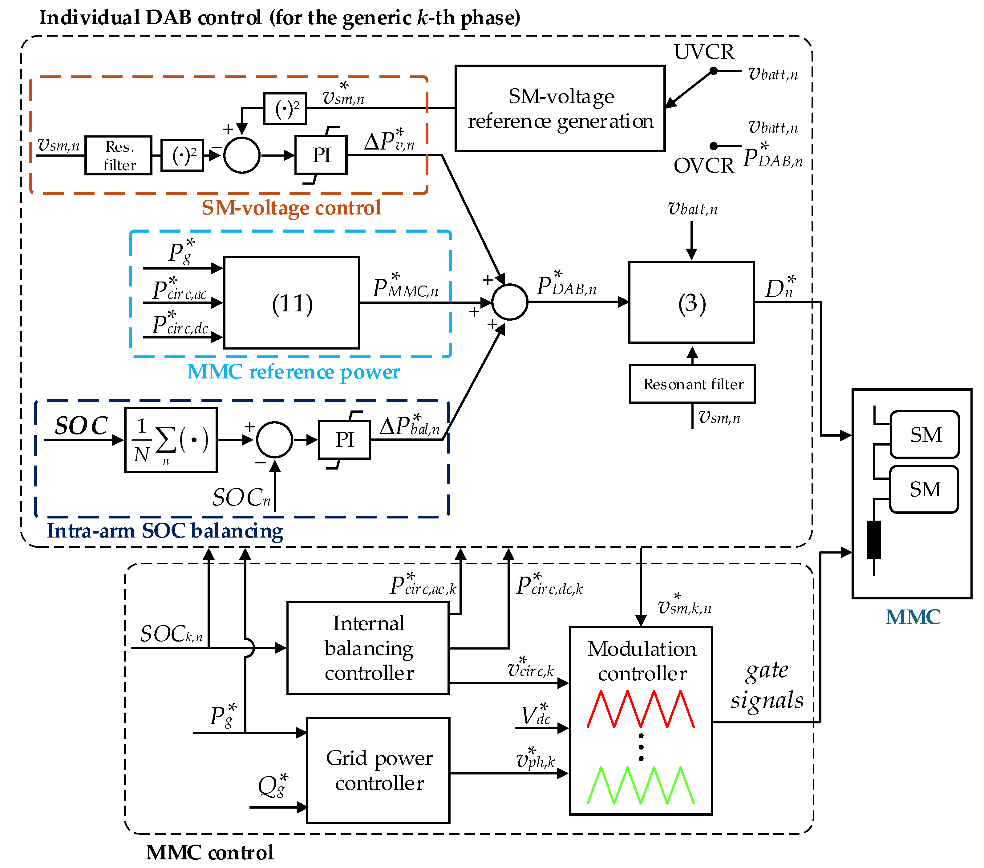
This article proposes active control for SM voltage regulation in an MMC integrating battery storage systems through DAB converters, with the objective of enhancing the overall power-conversion efficiency. In particular, assuming that the DAB converters employ SPS modulation, which is preferred because of its simplicity [
22], two control strategies were proposed, and their efficiencies were evaluated. The first strategy regulated the DC voltage of the DAB primary bridge to match the secondary-side battery voltage, which was adjusted based on the turns ratio of the high-frequency transformer. By equalizing the voltages on both sides of the DAB, this approach ensured ZVS operation and reduced the reactive-power circulation within the converter. The second strategy determined the voltage of the DAB primary-side bridge, which was connected to the MMC capacitor, with the goal of minimizing the total losses of the entire power-conversion system. This included the losses associated with both the AC-side power exchange and those incurred within the SM stages themselves.
Although this method achieved higher efficiency, it was more complex to implement as a result of the additional control requirements. It is worth emphasizing that the proposed control technique distinguished itself from existing approaches reported in the literature by enabling variable voltage regulation, as opposed to conventional fixed-voltage control. While the submodules could operate below their rated voltage, this does not inherently necessitate converter oversizing through the addition of extra SMs. This is because standard system configurations typically include one or two redundant modules to ensure continued operation under fault conditions. The proposed control strategy capitalizes on this existing redundancy to enhance the overall system efficiency. In the event of a fault, the system can maintain its operation by dynamically adjusting the voltage setpoints of the remaining SMs.
The system under analysis employed the double-star chopper cell (DSCC) configuration; however, the proposed control strategies are adaptable to any modular multilevel converter topology that provides a degree of flexibility in SM voltage control. The overall system efficiency was evaluated numerically in MATLAB® 2024b for the analyzed voltage-regulation algorithms. Finally, MATLAB-Simulink® simulations were conducted to analyze the impact of capacitor voltage oscillations on the proposed strategies.
2. System Topology and Operating Principle
This study investigated an MMC in a double-star chopper-cell configuration with batteries integrated through DAB converters, as illustrated in
Figure 1. The converter had three legs, corresponding to the three phases. Each leg was further divided into two arms, designated as the upper and lower arms, which were interconnected via two arm impedances,
Zarm. The midpoint between the arm impedances served as the converter output terminal. Each arm included
N SMs connected in series, with each SM integrating an isolated DC–DC stage based on a dual-active bridge topology. A battery was connected to the secondary terminal of each DAB, which enabled a distributed and redundant energy storage system. Therefore, the converter SM had three stages: the MMC half-bridge, DAB primary-side, and DAB secondary-side stages. The MMC half-bridge and DAB primary stages were interconnected via capacitor
Csm. The primary function of the MMC half-bridge stage was to generate the AC voltage needed to enable the power exchange between the grid and converter. Meanwhile, the DAB stages supported power transfer between the AC side and battery system. In the application considered, the MMC global DC bus was not connected to any load; however, in principle, an MV DC port could also be integrated into the system. Finally, the AC terminals of the MMC were connected to the MV grid through a transformer.
According to
Figure 1, for each
k-th phase of the converter (with
k ∈ {
a,
b,
c}), considering null the zero-sequence of the AC voltages, the following equations can be written:
with
Here, vu,k and vl,k represent the upper and lower arm voltages, respectively, and vph,k is the phase-arm voltage component responsible for regulating the output converter currents (iph,k) at the point of connection represented by voltage vg,k. The term vcirc,k denotes the circulating arm voltage component, which is responsible for regulating the circulating current (icirc,k) and managing the internal converter energy flow. Additionally, vdc represents the converter DC-bus voltage. Lastly, Rarm and Larm are the arm resistance and inductance, respectively, which together constitute the arm impedance (Zarm).
2.1. Generalities Related to Dual-Active Bridge Converters
To analyze the operations of the DAB converter, reference can be made to
Figure 1. The DAB comprised two full bridges connected via a high-frequency transformer, which ensured galvanic isolation. The DC voltage of the DAB primary-side stage, which was shared with the MMC half-bridge stage, is denoted as
vsm, while the DC voltage of the DAB secondary-side stage, which is connected to the battery, is denoted as
vbatt. Based on the considerations discussed in the introduction, the single-phase shift control method was adopted in this study. This control strategy involves imposing two high-frequency square waves on the two bridges, each with a constant 50% duty cycle and specific phase shift (
ϕ) between them that determines the power transferred between the two sides. Under SPS control, the power of the DAB converter,
PDAB, can be expressed as follows [
15]:
where
D =
ϕ/
π represents the p.u. phase shift,
ns is the transformer turns ratio,
fs,DAB is the DAB switching frequency, and
Ld is the inductance required for power transfer. This inductance can be realized either through the leakage inductance of the transformer alone or by adding an external inductor in series with the transformer. In this study,
PDAB was considered positive when the battery was charging and negative when it was discharging.
The SPS is a widely used modulation method for DAB converters because of its simplicity and ability to achieve the zero-voltage switching of components, thereby reducing switching losses. However, this operation is guaranteed only in the vicinity of the nominal transfer ratio, defined by
ns. When the input-to-output voltage ratio deviates significantly from
ns, soft switching is lost, and reactive power starts flowing between the primary and secondary sides of the converter, which substantially degrades the overall performance. Referring to points
i1 and
i2 indicated in the waveforms of
Figure 2, the soft switching turn-on of the components occurs when
i1 > 0 and
i2 > 0. In this case, the current direction ensures that the output capacitances of the turning-on MOSFETs are discharged by the inductor current. The soft-switching process has been extensively described in refs. [
23,
24]. The values of
i1 and
i2 can be determined based on the inductor current.
By imposing the zero-voltage switching conditions, i.e.,
i1 > 0 and
i2 > 0, and moving to the per-unit phase shift,
D, it is possible to retrieve the limit phase shift
Dlim as follows [
25]:
with
Voltage conversion ratio
M can be defined as follows:
when
D <
Dlim and the battery is charging if one of the following applies:
If M < 1, soft switching is lost in the secondary-side bridge (i.e., the receiver bridge).
Conversely, if M > 1, the primary-side bridge (i.e., the transmitter bridge) loses soft switching.
Similarly, the following occurs during reverse power flow (i.e., battery discharging):
If M < 1, soft switching is lost in the secondary-side bridge (i.e., the transmitter bridge).
If M > 1, soft switching is lost in the primary-side bridge (i.e., the receiver bridge).
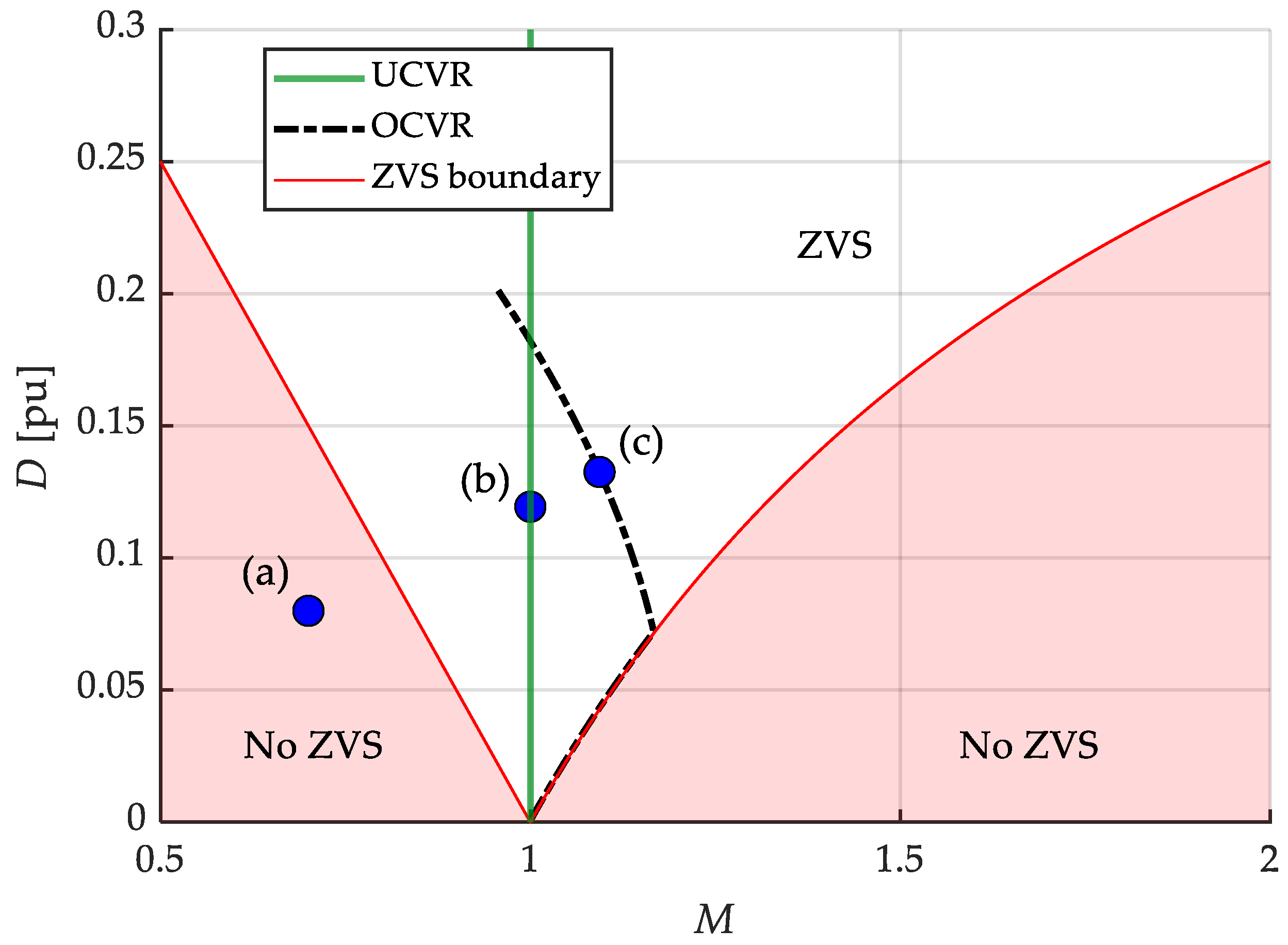
The ZVS boundary is reported in
Figure 3 as a function of
M and
D. From
Figure 3, it is evident that the soft-switching region narrows under a low DAB power (i.e., light-load conditions and low phase shift) or when
M deviates significantly from unity.
2.2. Proposed Voltage-Regulation Strategies
As shown in Equation (5), if SM voltage vsm is kept constant, conversion ratio M becomes dependent on the battery voltage. Because the battery voltage varies with the SOC during operation, deviations of M from unity may cause the DAB to operate outside its soft-switching region or lead to increased reactive-power circulation. However, because the battery voltage is influenced by the power exchanged with the grid and cannot be directly controlled, the DAB primary-side voltage, i.e., vsm, can be actively regulated to compensate for these variations. This regulation enhances the overall converter performance and maintains high efficiency under varying operating conditions.
This study investigated two control strategies: the unitary voltage conversion ratio (UVCR) strategy and the optimal voltage conversion ratio (OVCR) strategy. The UVCR approach adapts
vsm based solely on measurements of battery voltage (
vbatt) and transformer turns ratio (
ns), which enforces unitary conversion ratio (
M). As illustrated in
Figure 3, this enables operation within the ZVS region and reduces the reactive-power circulation resulting from large mismatches between the DAB DC-side voltages. However, for a given power reference and operating voltage, the value of
M directly influences the RMS current through the DAB inductor, core losses, and switching losses in both the high-frequency transformer and MMC half-bridges. Therefore, operating with a unitary conversion ratio may not yield the most efficient operating point. To address this limitation, the OVCR strategy determines the DAB primary-side voltage,
vsm, to minimize the total power losses of the overall power-conversion system. These include the losses in all of the SM stages, as well as those associated with AC-side power exchange. The optimal operating point (
vsm) is obtained by solving the following optimization problem:
In Equation (6),
denotes the losses in a single MMC half-bridge stage, while
refers to the losses in a single DAB stage. A detailed evaluation of the relevant loss components is provided in
Appendix A. The proposed control strategy relies on knowledge of the system parameters; therefore, any deviation from nominal values may lead to suboptimal performance. While this approach ensures optimal converter efficiency, it introduces additional complexity because it requires solving an optimization problem to determine the DAB primary-side voltage based on the battery side voltage and analytical expressions for DAB conduction and switching losses, as well as MMC half-bridge switching losses. Given the reference DAB power,
PDAB, measured battery voltage
vbatt, and known converter parameters, the optimal value of
vsm that minimizes the total power conversion losses can be identified. However, because the analytical solution of this optimization problem is not straightforward, a numerical iterative approach may be adopted. This can be implemented either through real-time computation or by using a precomputed lookup table generated offline. The latter option simplifies real-time implementation while still enabling near-optimal performance. The trajectory corresponding to the minimum total converter losses as a function of
M and
D is reported with a black line in
Figure 3. Importantly, the proposed voltage-regulation approach is independent of the direction of the power flow.
In
Figure 3, the regulation actions for the UVCR and OVCR control strategies are qualitatively represented by dots labeled (a) and (b), and (a) and (c), respectively. These dots indicate the DAB operating points. Point (a) represents a potential operating point of the DAB when the primary-side voltage is not adjusted. In this scenario, soft switching is lost, and the DAB reactive power is high. In the case of the UVCR strategy, the voltage control strategy aims to shift the operating point from (a) to (b) to enforce unitary conversion ratio
M. This ensures the ZVS operation and reduces the reactive power, offering a straightforward and robust control solution. In contrast, the OVCR strategy aims to shift the operating point from (a) to (c) by adjusting
vsm. This regulation aligns the DAB operation with the trajectory of minimum total converter losses, thereby maintaining soft-switching conditions while improving the overall system efficiency.
A comparative summary of the proposed strategies is presented in
Table 1.
2.3. Design Constraints and Voltage Range Considerations
Regardless of whether the control strategy is based on the UVCR or OVCR methodology, it is crucial to select an appropriate range for the DAB primary-side voltage to ensure continuous operation and power exchange with the main grid while avoiding high-voltage-rating components. This selection also determines the number of MMC SMs. In the context of the converter application analyzed in this paper, i.e., the integration of battery storage systems, the primary-side DAB voltages, which are proposed to be regulated to improve the converter performance, are influenced by the battery SOC and power exchange. As shown in
Figure 3, under the UVCR strategy, the DAB primary-side voltage is always equal to
nsvbatt, whereas the OVCR strategy requires the regulation of this voltage to values either above or below
nsvbatt.
The DAB secondary-side voltage range depends on the battery open-circuit voltage (
VOC), battery internal resistance (
Rbatt), and battery current (
ibatt). The latter is determined by the power exchange and battery voltage and must remain within the ratings of the DAB secondary-side bridge. The minimum and maximum voltages on the DAB secondary side at rated current
Ibatt can be expressed as follows:
In particular, represents the minimum voltage and corresponds to operation at the lowest allowed SOC, i.e., SOCmin, when the battery is discharging. Conversely, represents the maximum voltage, which corresponds to operation at the highest allowed SOC, i.e., SOCmax, when the battery is charging. In this study, the maximum and minimum allowed SOC values were set to values below 100% and above 0%, respectively, in order to preserve the life of the battery.
On one hand, it is necessary to ensure that the AC-side quantities are correctly modulated when the primary-side voltages are at the minimum voltage level (
). For the UVCR, this corresponds to
ns. However, as illustrated in
Figure 3, for the OVCR,
can fall below
ns. To avoid an excessive number of converter SMs, this minimum voltage can be constrained to a predefined lower bound—albeit at the expense of reduced efficiency. Assuming operation under linear PWM, the sum of the converter arm DC voltages must be at least twice the peak value of the phase voltage component. Consequently, the number of converter SMs in each arm can be defined as follows:
where
Vg,ll is the line-to-line grid voltage, and
γ is a margin coefficient that accounts for active/reactive power regulation, internal balancing, and SM capacitor oscillations caused by harmonic components.
On the other hand, to prevent excessive current ripple and avoid exceeding component voltage ratings, a limit can be imposed on the primary-side voltage to ensure that
vsm does not exceed a certain threshold. If this limit is reached, the converter must deviate from the chosen trajectory accordingly. This constraint can be relevant for the OVCR strategy, as observed in
Figure 3.
4. Case Study and Simulation Results
This section provides a comparative analysis of the system efficiencies when the UVCR and OVCR control strategies are employed, along with the results of numerical simulations conducted in MATLAB-Simulink®. Initially, each of the proposed control strategies for the power conversion system was evaluated and compared to baseline cases in which the DAB primary-side voltage was maintained at a fixed value. The efficiency assessments were performed under the assumption of constant DC voltages in the MMC SM stages. Subsequently, time-domain simulations were carried out to validate the efficiency evaluation methodology, taking into account the second-harmonic content inherent in the MMC SM voltages.
The proposed control strategy was tested on a 5 MVA MMC that integrated batteries at the submodule level isolated through a DAB converter, with a total energy capacity of 4.7 MWh. The converter output voltage was 3.3 kV (line-to-line). It was designed to be connected via a transformer to the MV AC distribution grid, which was assumed to operate at 11 kV. The number of arm SMs depended on the battery pack integrated within each arm and the transformer turns ratio of the DAB SM stage. The battery storage system was modeled based on Corvus Energy Orca modules (Corvus Energy, Richmond, BC, Canada), which are lithium-ion nickel-manganese-cobalt batteries designed specifically for maritime applications. The battery integrated into each individual SM was sized using data from the manufacturer’s datasheet [
28]. Details of the battery pack are available in
Table 2. The SOC–VOC curve of the battery was derived by scaling the NMC battery curve from [
29].
The DAB converter parameters, listed in
Table 3, were determined based on the specifications of the MMC and batteries, as discussed in
Section 2.1 and
Section 3.2. The DAB power rating had to accommodate both the grid power contribution and an additional margin for circulating and internal balancing power. For the application analyzed in this study, the rated DAB power was set to
Pr,DAB = 125 kW. The rated voltages of the primary and secondary stages were equal to those of the DC-side MMC half-bridge and battery, respectively. Given that the transformer turns ratio was unity, the voltages on both sides were identical and assumed to be equal to
, i.e., 1000 V. The minimum battery voltage was computed assuming the battery operated at the minimum allowable SOC (10%) while absorbing the rated power (125 kW), resulting in
= 924 V. Similarly, the maximum battery voltage was computed assuming the battery operated at the maximum allowable SOC (90%) while injecting the rated power, resulting in
= 1096 V. The primary-side minimum and maximum voltages depended on the control strategy adopted: under the UCVR strategy, they matched
and
, respectively. Under the OCVR strategy, they were determined numerically, considering the entire DAB operating range, resulting in a minimum voltage of 857 V and a maximum voltage of 1045 V. To avoid oversizing the number of submodules, the optimization function used for the OVCR was constrained by setting a lower bound of
= 924 V. Moreover, by setting the switching frequency to 20 kHz and the p.u. phase shift to
D = 0.25 when the converter exchanged its rated power with the battery operating at its minimum voltage, the leakage inductance was calculated to be 33.6 μH using (3). This sizing criterion ensured that the DAB converter could operate down to the minimum allowable battery SOC. Furthermore, for both DAB SM stages, the 1700 V—Wolfspeed CAS300M17BM2 SiC-MOS device (Wolfspeed, Durham, NC, USA) was assumed [
30], while for the MMC half-bridge stage, the 1700 V—Wolfspeed CAB650M17HM3 SiC-MOS device (Wolfspeed, Durham, NC, USA) was used [
31]. As the DAB-side voltages for both proposed strategies remained within the voltage specifications of the switching devices, no additional voltage limitations were required.
Finally, given the battery parameters and remembering that a unitary transformer turns ratio for the DAB converters was chosen, the number of SMs was determined using (8) as follows:
A 15% margin was included to account for power regulation, circulating current control, and SM capacitor oscillations. All the MMC parameters are reported in
Table 4.
4.1. Efficiency Evaluation
The variation of the primary-side DAB voltage made it necessary to evaluate the efficiencies of both the DAB and MMC half-bridge stages, because these directly affected the switching losses of the converters. Losses were calculated in MATLAB
® using closed-form expressions and the system parameters provided in
Appendix A, which included a junction temperature for the semiconductors of 90 °C. Because the voltage regulation was independent of the power flow direction, the analysis was conducted under battery charging conditions. The evaluation included switching and conduction losses in both the DAB and MMC half-bridge stages, Joule and core losses in the DAB transformer, and Joule losses in the MMC arm inductors.
This study was conducted under the following assumptions: (i) all of the SMs in the converter operated at the same power setpoint; (ii) circulating currents were absent; (iii) the arm current ripple was negligible; and (iv) the voltage on the DAB primary side was constant, disregarding fundamental and second-harmonic oscillations. Assumptions (i) and (ii) were justified by the storage-system application, where significant internal imbalances were not expected. Assumption (iii) was supported by the low harmonic content in multilevel converter currents, while assumption (iv) was based on the fact that in MMCs, each phase can be considered a standalone single-phase system. Single-phase systems are known to exhibit power oscillations at twice the fundamental frequency. These power oscillations generated voltage oscillations in the MMC SMs, potentially affecting the behavior of the proposed algorithm. The impact of SM voltage oscillations was evaluated using time-domain simulations, as discussed in
Section 4.2.
The efficiency of the system was analyzed as a function of both the grid power reference (
Pg) and battery voltage (
vbatt), assuming the two voltage control strategies described in this paper. The cases under analysis were as follows: (i) UVCR control strategy—the SM voltage on the DAB primary side was set equal to the battery side voltage, i.e.,
M = 1, as shown in
Figure 3; (ii) OVCR control strategy—the SM voltage was adjusted to follow the optimal efficiency trajectory, as illustrated in
Figure 3; (iii) fixed DAB primary-side voltage, specifically,
vsm =
= 924 V; (iv) fixed DAB primary-side voltage, specifically,
vsm =
= 1096 V; and (v) fixed at rated DAB primary-side voltage, specifically,
vsm =
Vsm,r = 1000 V. In cases (i) and (ii), the SM voltage on the DAB primary-side could vary according to the battery voltage range, i.e.,
.
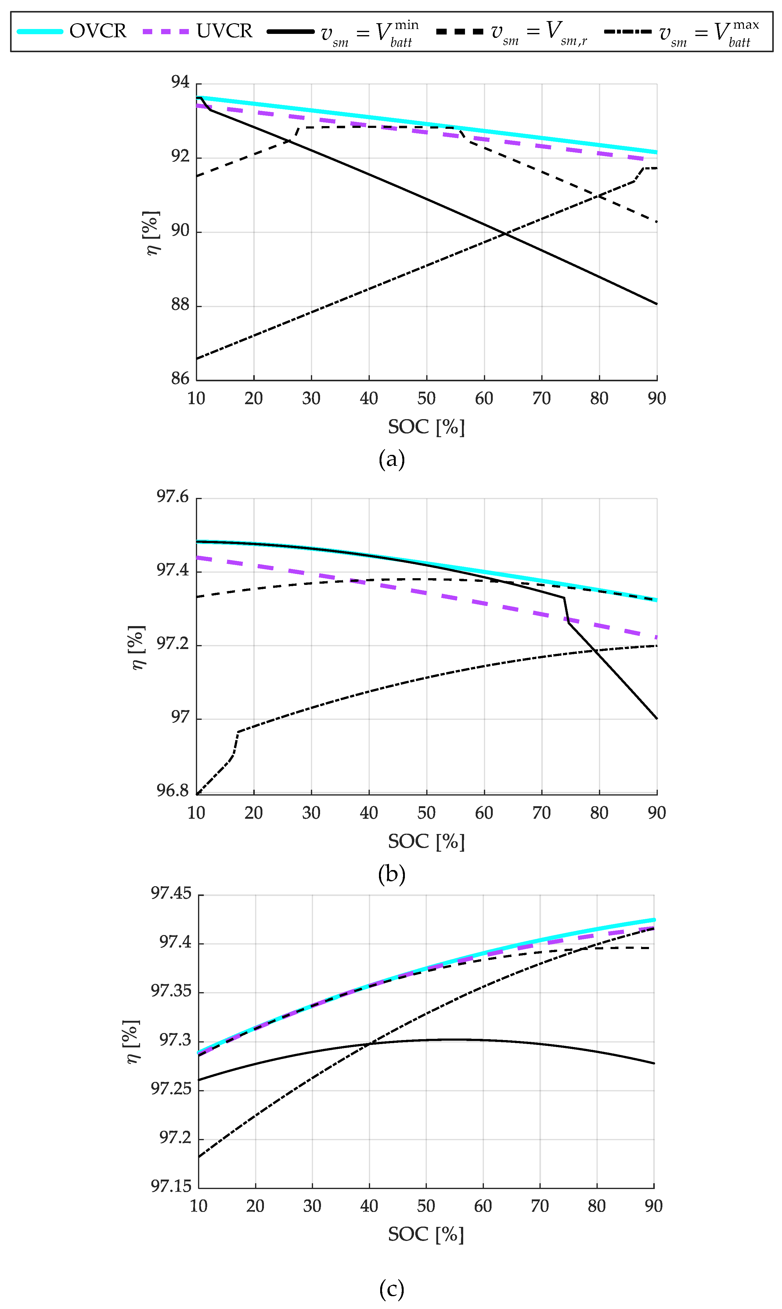
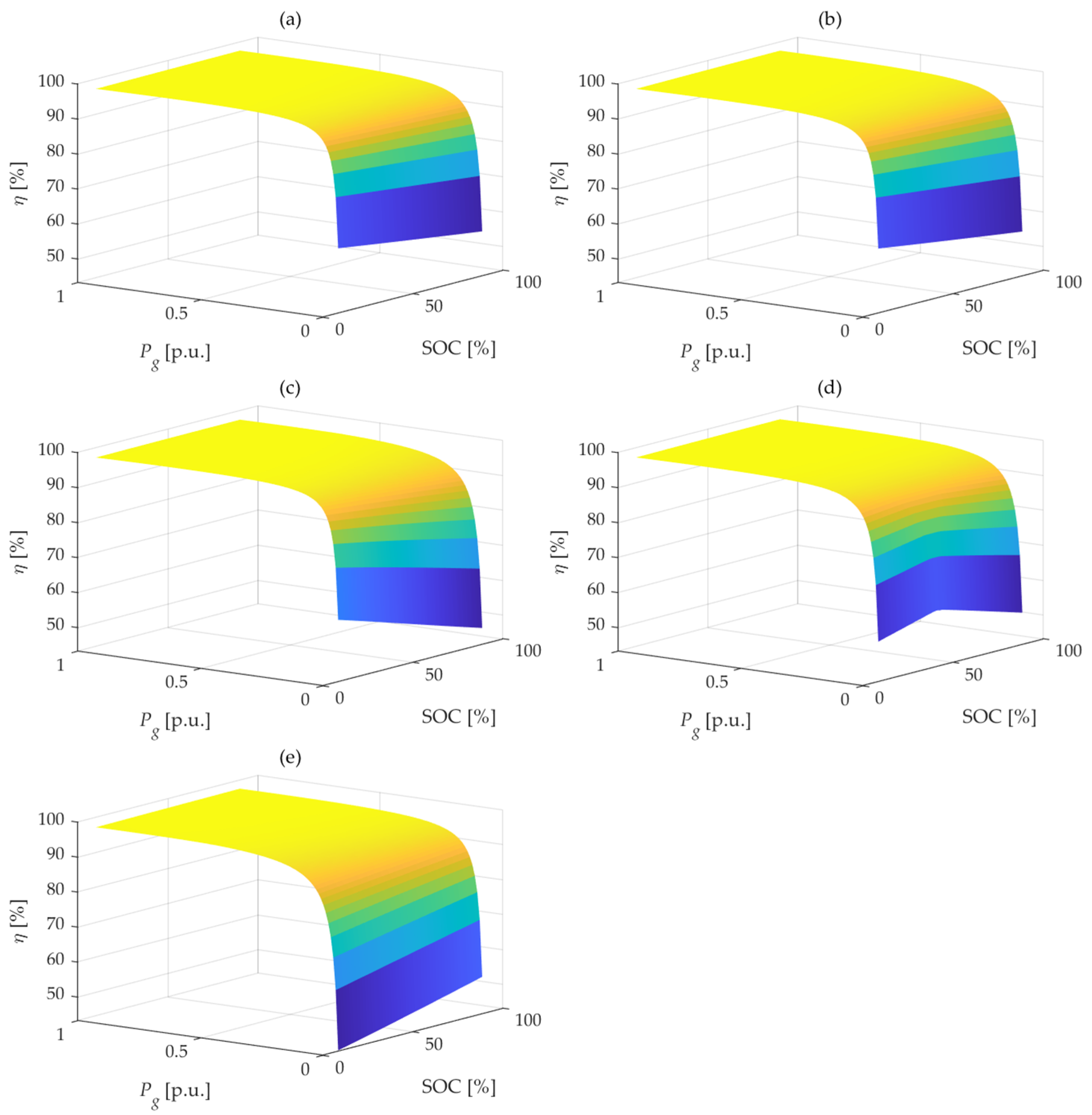
The results are reported as a function of the battery SOC in
Figure 6, for 10%, 50%, and 100% of the nominal power. In
Figure 6a, which corresponds to power exchange at 10% of the nominal power, the UVCR and OVCR control strategies exhibit the highest efficiencies across the entire battery voltage range. Comparing the two voltage-adaptive strategies, the OVCR method achieved an efficiency gain of up to 0.3% over UVCR at a 10% power operation with the minimum battery voltage (
Figure 6a).
In contrast, fixing the SM voltage on the DAB primary side at one of the three predefined values (, , or Vsm,r) did not provide any advantage over the active voltage regulation strategies because the resulting efficiency curves either fell below or coincided with those of the active voltage regulation methods. Additionally, among these fixed-voltage approaches, the efficiency varied across the battery voltage range, with one being more efficient than the others in different regions. As expected, each predefined voltage value achieved higher efficiency in the region where the battery voltage (vbatt) was the closest to its respective predefined value. The efficiency decreased in regions with a large DAB voltage ratio, where increased reactive power losses occurred or where, because of a low power setpoint, the operation fell outside the soft-switching region. Notably, active voltage regulation under low-load conditions could improve the efficiency by a few percentage points.
Figure 6b presents the results for the converter operating at 50% of its nominal power. Overall, there were no significant differences in efficiency across the strategies. At low battery voltages, the OVCR and UVCR efficiencies were comparable to that obtained when the DAB primary-side voltage was fixed at
vsm =
, while at higher battery voltages, they aligned more closely with the case of
vsm =
Vsm,r = 1000 V. Conversely, selecting
vsm =
proved to be inefficient, yielding the lowest efficiency across most of the battery voltage range. Comparing the two voltage-adaptive strategies, the OVCR method achieved an efficiency gain of up to 0.1% over UVCR at 50% power operation with the minimum battery voltage.
Finally, the efficiency at full power is presented in
Figure 6c. As in the case of 50% nominal power, there were no significant differences in the overall efficiencies of the proposed strategies, which exhibited nearly identical performances. All of them outperformed the fixed-voltage strategies.
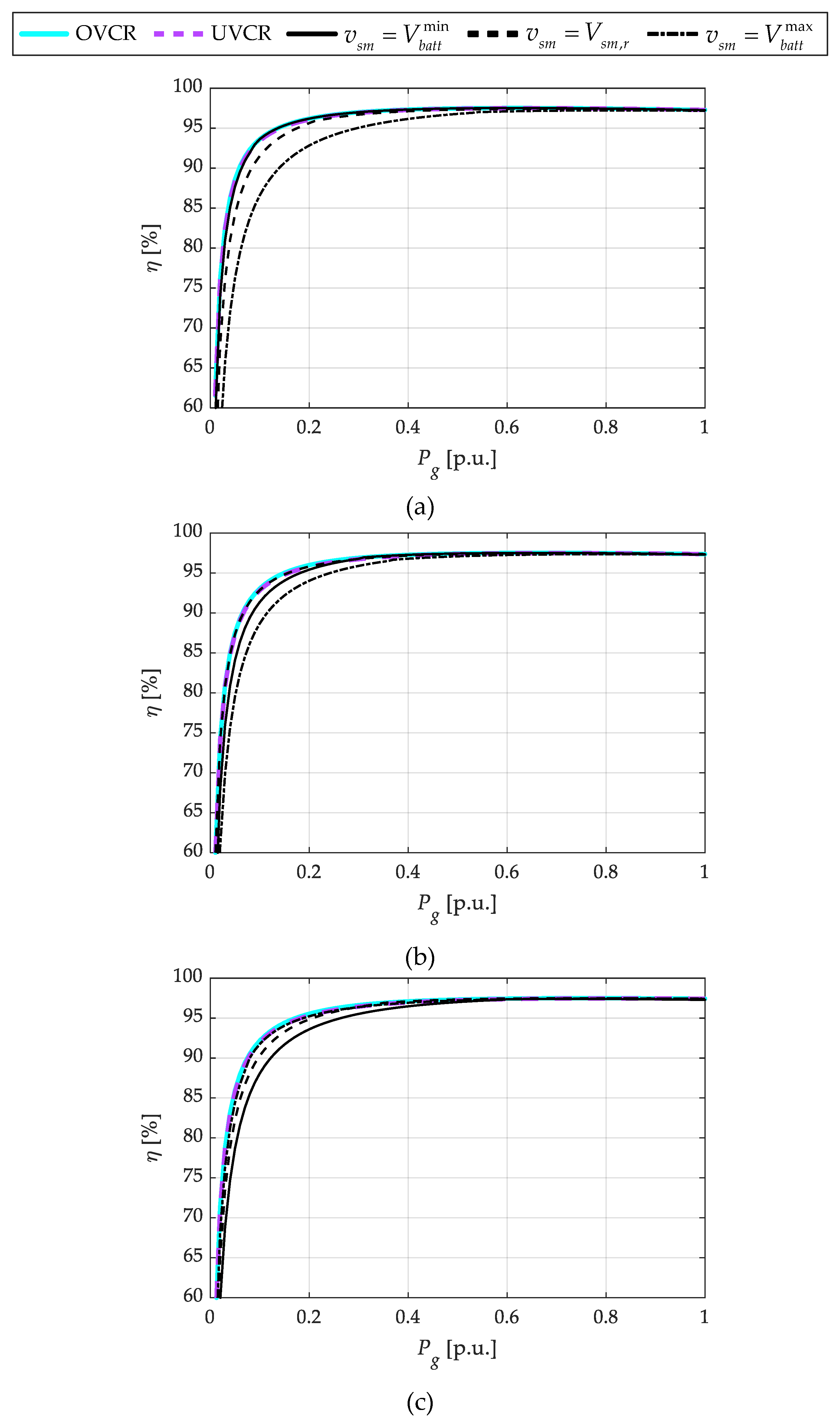
Figure 7a–c present the efficiencies of the control strategies as a function of the converter per-unit power for the three different battery SOC levels: 10%, 50%, and 90%. These figures highlight that the primary advantages of DAB primary-side voltage regulation emerged in the low-power range, where the efficiency varied by several percentage points as a result of the effects of the soft-switching and reactive power circulation. At higher power levels, the efficiency differences became less pronounced. Maintaining the DAB primary-side voltage at a fixed potential resulted in high efficiency only for the battery voltage that corresponded to that value. Considering as a base case the control of the MMC half-bridge stage voltage fixed at its rated value (
vsm =
Vsm,r), the simulation results indicated that both OVCR and UVCR improved the efficiency by more than 6% during low-power and low battery SOC operation (
Figure 7a) and by over 2% at a higher battery SOC (
Figure 7c).
In terms of the power losses, during the low-power and low-battery SOC operation, the UVCR and OVCR strategies reduced losses by up to a factor of 1.4 compared to the baseline. Similarly, during the low-power and high-battery SOC operation, UVCR and OVCR reduced the losses by a factor of up to 1.3 times.
Figure 8 presents a comprehensive overview of the efficiency maps corresponding to the converter operating points. Each subplot specifically illustrates the efficiency map for a given control strategy under various battery SOC and output-power levels.
In conclusion, as demonstrated in
Figure 6,
Figure 7 and
Figure 8, the ability to vary the primary-side voltage of the DAB SM stage significantly enhanced the efficiency. Among the evaluated strategies, the OVCR approach exhibited the best overall performance. However, its implementation was more complex as a result of system nonlinearities. Therefore, the UVCR strategy presented a viable alternative, offering a performance comparable to that of the OVCR strategy while being simpler to implement.
4.2. Impact Assessment of Oscillations in MMC Capacitor Voltages
The MMC integrating distributed batteries through DAB converters was simulated in MATLAB-Simulink® to evaluate and discuss the impact of MMC capacitor voltage oscillations on the proposed voltage-control strategies. Because these considerations were independent of the specific voltage reference strategy, the UVCR strategy was adopted for simplicity. A hybrid modeling approach was employed. Because of the difference in operating frequencies, the DAB converter was represented by an average model, neglecting its switching dynamics, while the MMC was modeled using a detailed switching representation. Additionally, the battery capacity was scaled by a factor of 60 to enable the visualization of the SOC variation within a reasonable simulation time.
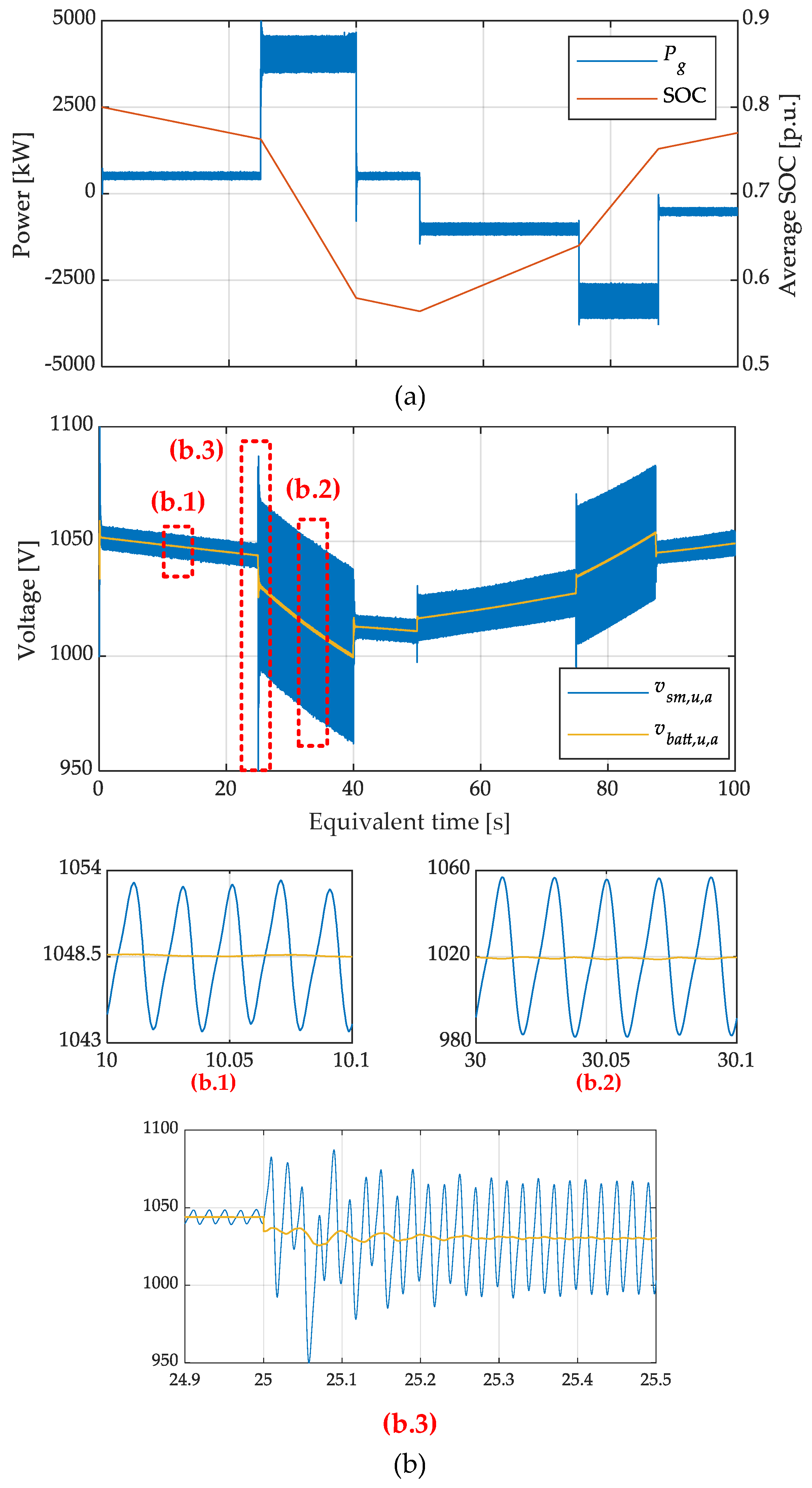
Figure 9a presents both the power exchanged with the grid by the converter, where positive values indicate injection into the grid and negative values indicate absorption, and the average SOC of the batteries integrated into the converter.
Figure 9b shows the average values of the capacitors and battery side instantaneous voltages within the upper arm of phase-
a (
vsm,u,a and
vbatt,u,a, respectively), which were computed as follows:
where
vsm,u,a,n and
vbatt,u,a,n are the individual capacitor and battery voltages of the
n-th SM of phase-
a, respectively.
The enlarged graphs shown in (b.1) and (b.2) of
Figure 9b illustrate the impact of capacitor voltage oscillations on the proposed control strategy at a steady state. These oscillations caused the instantaneous DAB primary-side voltage to fluctuate around the optimal voltage point established by the control. A comparison shows that the amplitude of these oscillations depended on the current flowing through the arm, which was directly influenced by the active and reactive power exchanged. As demonstrated through the efficiency evaluation, the proposed control was especially beneficial at low power levels, where the oscillation amplitude was lower and the actual voltage remained close to the optimal value. For example, the graph in (b.1) corresponds to an operation with 10% active power exchange and reveals an oscillation of ±5 V around an average value of 1048.5 V, which corresponds to a total variation of approximately 0.95%. Consequently, ratio
M varied between 0.9948 and 1.0043, remaining very close to unity. Thus, the impact on efficiency compared to the assumption of a fixed voltage can be considered negligible. High-power operation is depicted in (b.2), which shows an oscillation amplitude of ±38 V around an average value of 1020 V, corresponding to a total voltage variation of approximately 7.45%. In this case, ratio
M varied between 0.963 and 1.037. However, as shown in
Figure 7, the sensitivity of the converter efficiency to the DAB primary-side voltage value was low at high loads. Therefore, it is reasonable to conclude that the impact of voltage oscillations on the DAB efficiency can be neglected. Finally, (b.3) in
Figure 9b illustrates the transient response of the voltage regulation following a power step. As shown, the new voltage setpoint was reached within a few milliseconds, enabling the converter to operate in a manner that enhanced the overall efficiency.
6. Conclusions
Power-conversion systems based on MMCs, integrating DAB converters at the submodule level, represent a valuable solution for interfacing distributed battery packs while achieving modularity and isolation. This converter architecture can be applied in storage systems for grid applications, charging stations, and onboard storage for modern vessels, among others.
This study investigated control strategies for regulating the DAB voltage and enhancing the overall efficiency. Specifically, two control strategies were analyzed, demonstrating a significant reduction in power losses under specific operating conditions. The results highlighted the potential of the proposed methods for improving the performance of modular power-conversion systems. Although the results presented were based on simulations, the proposed methods are directly applicable to hardware prototypes and real-world systems. In this regard, this study provided practical insights into the implementation trade-offs of each strategy, which will support informed decision-making in the design of converter control systems. Future research will focus on the optimization of these control techniques for real-time embedded applications.
Finally, although the presented results pertained to an MMC based on the double-star chopper cell configuration, future studies will extend the analysis to alternative MMC topologies. The goal will be to identify the most efficient configurations tailored to specific application requirements.


