A comprehensive analysis of the thermal performance of finned square cavities is presented based on 9000 numerical simulations. This number arises from a structured multi-parametric sweep involving five key physical and geometric parameters: Rayleigh number (Ra), Prandtl number (Pr), fin length (Lfin), fin vertical position (Yfin), and fin-to-fluid thermal conductivity ratio (kfin/k), along with an additional sub-loop over fin thickness (Wfin). Each parameter was discretized over a physically meaningful range informed by prior studies and preliminary sensitivity analysis. Specifically: Ra was varied over five values (10, 102, 103, 104, 105); Pr included six values (0.1, 0.5, 0.71, 1, 5, 10); fin length used five values (0.1, 0.3, 0.5, 0.7, 0.9); vertical position covered five values (0.1, 0.3, 0.5, 0.7, 0.9); fin thickness included three values (0.001, 0.01, 0.1); and kfin/k spanned four values (1, 10, 100, 1000). The selected conductivity ratio range (kfin/k = 1 to 1000) captures a broad spectrum of thermal performance scenarios. While common fin materials, such as aluminum and copper, in air yield much higher ratios, typically between 7800 and 15,000, the upper bound of 1000 is sufficient to represent the onset of asymptotic behavior, allowing us to evaluate when increased conductivity no longer yields practical thermal gains.
The discussion is structured around key aspects of heat transfer behavior, including the influence of fin geometry and conductivity, regime-dependent trends in the Nusselt number, spatial sensitivity to fin placement, coupled Rayleigh-Prandtl interactions, and optimal configurations under convective conditions. Although no explicit critical Rayleigh number is reported, the progression from conduction- to convection-dominated regimes is captured qualitatively through variations in Nusselt number, flow structure, and fin sensitivity across the parametric space.
4.1. Parametric Optimization of Fin Geometry and Conductivity for Enhanced Natural Convection Flow and Heat Transfer
The analysis begins with a detailed assessment of how fin geometry and thermal conductivity influence heat transfer across varying Rayleigh and Prandtl numbers.
Table 3 presents a detailed summary of the Maximum Nusselt Number Ratio (NNR) achieved across a wide range of Rayleigh numbers (
Ra = 10 to 10
5) for six Prandtl numbers (
Pr = 0.1 to 10), using a fixed fin conductivity equal to that of the fluid. This configuration isolates pure geometric effects, as the fin contributes no additional conductive advantage.
At Ra = 10, all Prandtl numbers yield an NNR of exactly 1.00001 with minimal sensitivity to Pr. This confirms that under conduction-dominated conditions, the fin is thermally passive and does not interfere with heat transport. The optimal configuration, characterized by a short fin (Lfin = 0.1), positioned near the top (Yfin = 0.9), and very thin (Wfin = 0.001), remains consistent across all Pr values. The symmetry and thermal neutrality at this regime indicate that the fin neither perturbs the broad thermal boundary layer nor contributes to conduction enhancement.
As Ra increases to 102, the system begins transitioning into a weakly convective regime. The NNR slightly drops to 0.999984 for all Pr values, a negligible but consistent deviation. Interestingly, the associated Nusselt numbers ( ≈ 1.00144) remain near unity, reflecting that convective motion is emerging but remains symmetric and weak. Again, the optimal fin configuration remains unchanged, emphasizing that geometry still plays a passive role in this low Ra regime.
A more noticeable change occurs at Ra = 103, where the NNR further drops to approximately 0.9991–0.99912. This ~0.09% decrease across all Pr values marks the start of performance divergence due to convective plume interaction with the fin. While the optimal geometry (short, top-aligned, thin fin) persists, shows a clear dependence on Prandtl number, where it increases from 1.11 at Pr = 0.1 to 1.1168 at Pr = 10. This indicates that higher-Pr fluids, which have thinner thermal boundary layers, become increasingly sensitive to local flow obstruction caused by the fin.
At Ra = 104, the decline in NNR becomes more pronounced, dropping to a range of 0.9966–0.9976, representing a ~0.3% reduction in performance relative to the unfinned cavity. Here, the associated values show substantial growth, from 2.12 at Pr = 0.1 to 2.27 at Pr = 10, as buoyancy-driven circulation becomes dominant. Despite the increase in overall heat transfer, the embedded fin reduces relative efficiency due to distortion of the convective streamlines, particularly near mid-height. However, the table indicates that top-aligned fins still produce the best results under this neutral conductivity condition.
Finally, at Ra = 105, the NNR drops further to ~0.989–0.993, indicating that the inclusion of the fin results in a clear and consistent reduction in heat transfer efficiency. This decline is most severe at Pr = 0.5, where the NNR reaches a minimum of 0.9892. However, the absolute Nusselt numbers continue to rise across all Prandtl numbers, reaching as high as = 4.68 at Pr = 10, signifying that while heat transfer is intensifying with Ra, the presence of a fin hinders optimal flow circulation and increases flow resistance. Notably, the same geometry, short, thin, and top-aligned, remains optimal, suggesting that only minimal fin geometries can avoid disrupting strong convection patterns.
A notable observation from the results is the consistent discrepancy between the Maximum Nusselt Number Ratio (NNR) and the average hot-wall Nusselt number (), particularly at moderate-to-high Rayleigh numbers. For instance, at Ra = 105 and Pr = 10, the NNR drops below 0.991, implying a relative reduction in thermal performance due to the fin. However, the corresponding value exceeds 4.68. This contrast highlights a key insight that NNR is a normalized metric that compares finned performance to the unfinned baseline, accounting for added surface area. In contrast, reflects the absolute convective heat transfer on the hot wall. Therefore, while continues to rise with Ra and Pr due to more substantial buoyancy and thinner thermal boundary layers, NNR reveals the penalty introduced by the fin’s obstruction to flow, even if overall heat transfer improves. This distinction is critical for designers: a high does not always imply effective fin integration, NNR must be considered to assess whether the fin is enhancing or degrading relative thermal performance.
For kfin/k = 1, the inclusion of a fin provides no enhancement and can marginally degrade performance in convective regimes. This underscores the need for careful geometric tuning or material selection (with higher conductivity) to extract thermal benefits from embedded fins in naturally convecting enclosures.
Table 4 presents the variation in the Maximum Nusselt Number Ratio (NNR) and associated fin geometries across a range of Rayleigh numbers (
Ra = 10 to 10
5) for six Prandtl numbers (
Pr = 0.1 to 10) under a conductivity ratio of 10. This scenario introduces a moderate thermal enhancement potential, allowing the fin to act as a conductive bridge between the hot wall and the fluid, while still retaining sensitivity to convective dynamics.
At Ra = 10, the system remains in a conduction-dominated regime, yet the NNR rises to approximately 1.2495 for all Prandtl numbers, indicating a ~25% enhancement relative to the unfinned cavity. This improvement is attributed to the increased conductive capacity of the fin, which now contributes significantly to axial heat transport. The optimal geometry shifts slightly from the neutral case: the fin becomes longer (Lfin = 0.9), thicker (Wfin = 0.1), and is repositioned slightly lower (Yfin = 0.7), reflecting a design that maximizes surface area while remaining well within the diffusive envelope of the thermal field.
As Ra increases to 102, the NNR remains nearly unchanged (~1.2489), suggesting that the system still operates predominantly under conduction with emerging convective rolls having minimal interference. Notably, the associated average hot-wall Nusselt number () increases modestly to ~1.25 across all Pr values, reflecting incremental buoyancy effects. The optimal fin configuration remains unchanged at Ra = 10, reinforcing the idea that low-to-moderate Ra regimes benefit from large, thermally active fins, which function as extended heat exchangers with minimal flow resistance.
At Ra = 103, the influence of convective structures becomes evident. NNR decreases by ~5.7% to values ranging from 1.1773 to 1.1784, with a more pronounced drop compared to lower Ra levels. Despite this reduction in relative performance, the absolute heat transfer continues to increase, with ranging from 1.31 at Pr = 0.1 to 1.316 at Pr = 10. This behavior signals the onset of a transitional regime in which the previously favorable geometry (long and thick) begins to impede vertical flow, resulting in thermal shielding or local recirculation. Nonetheless, the fin remains top-aligned (Yfin = 0.9), indicating that high vertical placement continues to exploit rising thermal gradients.
A substantial shift occurs at Ra = 104, where the NNR falls below unity for all Pr values (0.9958–0.9967), indicating that the fin now reduces relative heat transfer performance compared to a smooth cavity. Yet grows significantly, reaching values from 2.11 (Pr = 0.1) to 2.27 (Pr = 10). This discrepancy suggests that although the fin still transfers heat effectively due to its high conductivity, it also begins to interfere with the established convective plume, especially in fluids with higher Prandtl numbers, where boundary layers are thin and plume alignment is more critical. The optimal geometry is now dramatically reduced: the fin becomes very short (Lfin = 0.1), extremely thin (Wfin = 0.001), and remains at the top (Yfin = 0.9), reflecting a design pivot toward minimal obstruction.
At Ra = 105, this trend continues and intensifies. NNR values drop further to a range of 0.9887 to 0.9931, confirming a persistent penalty in relative heat transfer. However, the absolute Nusselt numbers continue to rise sharply, reaching as high as = 4.68 at Pr = 10, indicating a highly active convective regime. Interestingly, the optimal fin configuration (short, thin, and top-mounted) remains the same as for Ra = 104, emphasizing that compact fins placed near high-gradient regions mitigate obstruction while preserving the conductive benefit. The data also shows that even with a tenfold conductivity contrast, enhancement diminishes at high Ra due to geometric misalignment with convective structures.
An important trend in
Table 4 is the increasing divergence between the NNR and
at higher Rayleigh numbers. For instance, at
Ra = 10
5 and
Pr = 10, the NNR is only ~0.9909, indicating a slight net degradation compared to the smooth cavity, while
exceeds 4.68, reflecting a vigorous convective regime. This contradiction underscores the dual nature of fin’s performance since
represents total heat removal or addition, while NNR contextualizes it by comparing against the baseline and accounting for geometric cost. A fin may appear beneficial based on
alone, but NNR reveals whether its inclusion is thermodynamically justified once the added surface area and potential flow disturbance are considered.
At moderate conductivity ratios (kfin/k ~ 10), fin integration yields substantial thermal enhancement only in conduction-dominant regimes (Ra ≤ 102), where large, centrally embedded fins serve as effective heat bridges. However, as convection strengthens (Ra ≥ 103), the benefits of high conductivity become increasingly limited by geometric interference with flow. The results demonstrate that conductivity alone is insufficient to guarantee enhanced performance, as geometry must be tailored to avoid disrupting established plume structures. At higher Ra, the optimal design shifts toward short, top-aligned, and minimally intrusive fins, which balance conductive advantage with convective compatibility. This underscores the need for integrated thermogeometric optimization in passive fin-assisted heat transfer systems.
Table 5 presents the thermal performance trends in square cavities equipped with highly conductive fins (conductivity ratio = 100) across a wide range of Rayleigh numbers (
Ra = 10–10
5) and Prandtl numbers (
Pr = 0.1–10). This configuration allows the fin to act as a strong axial conductor, facilitating lateral heat spreading even under weak convective motion.
At Ra = 10, the performance peaks across all cases, with NNR values consistently reaching 1.8524, independent of Pr. This represents an 85% improvement over the smooth cavity, signifying substantial conduction-driven enhancement. The optimal fin design is consistent across all fluids: a long fin (Lfin = 0.9), centered vertically (Yfin = 0.5), and relatively thick (Wfin = 0.1). In the absence of significant flow structures, this configuration leverages direct axial conduction into the fluid core without flow interference, acting as a highly effective thermal bridge.
At Ra = 102, the NNR remains virtually unchanged (1.8497), suggesting that the transition to convection is still too weak to disrupt the fin’s conductive role. The associated Nusselt numbers ( ≈ 1.85) are nearly identical to those at Ra = 10, confirming a conduction plateau where enhancement is governed solely by material properties and geometry, rather than by buoyancy. The geometry remains unaltered, showing that mid-wall, full-length fins are still optimal in quasi-static thermal environments.
By Ra = 103, convective activity becomes more influential. The NNR declines by ~10% to values between 1.6765 and 1.6793, marking a shift toward a mixed regime where flow begins to interact with the fin. The Nusselt numbers continue to increase ( ≈ 1.87), but the optimal fin position shifts upward (Yfin = 0.7), indicating the fin’s role has evolved from passive conductor to an active structure that must align with thermal plume development. Although the long fin is retained, the need for repositioning suggests that early obstruction effects are beginning to emerge.
At Ra = 104, a marked change occurs: NNR values fall to ~1.16–1.18, representing a further ~30% decline from the low-Ra peak. However, the absolute heat transfer continues to improve, with ranging from 2.51 to 2.64, depending on Pr. The optimal geometry is significantly reduced in length (Lfin = 0.1), vertically aligned at the top (Yfin = 0.9), and much thinner (Wfin = 0.001). This transition reflects a key turning point; large, centrally located fins are no longer viable. As buoyancy strengthens, plumes become sensitive to flow blockage, and only minimal, top-mounted fins are needed to avoid disrupting convective structures. Importantly, this design pivot occurs even though the fin still has high conductivity, indicating that geometric compatibility with the flow becomes more critical than conductive capacity.
At Ra = 105, NNR values drop further to approximately 1.003–1.031, approaching unity and signaling that the fin offers little to no net benefit over a finless cavity. Nonetheless, the Nusselt numbers increase significantly across all Pr values, with reaching approximately 4.05–4.74. This contrast highlights that the fin’s contribution becomes nearly neutralized by its interference with fully developed buoyant flow, despite its conductivity advantage. As before, the optimal fin remains short, thin, and top-aligned, demonstrating that in strong convection, only minimal geometry is required to preserve the flow structure without hindering efficiency.
A persistent trend across
Table 5 is the widening gap between the NNR and
at higher
Ra. For example, at
Ra = 10
5 and
Pr = 10, the system achieves a Nusselt number of 4.74; yet, the NNR is only 1.003, indicating almost no relative enhancement compared to the unfinned case. This reinforces the notion that absolute heat transfer performance can be misleading: while
increases with
Ra due to stronger convection, NNR reveals whether the fin is improving or impeding thermal performance relative to the baseline. In this regime, the fin’s conductive value is diminished by its disruptive presence, and only careful positioning and sizing can avoid performance degradation.
For high-conductivity fins (kfin/k ~ 100), maximum thermal enhancement occurs at low Rayleigh numbers, where conduction dominates and flow remains symmetric. In these cases, long, centrally located fins serve as efficient thermal bridges. As Ra increases and convection becomes dominant, the benefit of high conductivity diminishes sharply, and fin-induced flow obstruction leads to progressively lower NNR values. Even though the overall heat transfer () continues to rise, the relative advantage of using a fin drops nearly to zero. To retain any thermal benefit, the fin must be minimal in size, placed near the wall edge, and aligned with dominant plume trajectories. This underscores a critical design insight: in high-Ra environments, geometry and flow compatibility outweigh conductivity as the primary determinant of passive enhancement.
Table 6 illustrates the impact of using ultra-conductive fins, with conductivity ratios as high as 1000, on natural convection heat transfer across a broad range of Rayleigh numbers (
Ra = 10
2 to 10
5) and Prandtl numbers (
Pr = 0.1 to 10). This regime represents a near-ideal conduction scenario, where the fin offers minimal internal thermal resistance and behaves nearly as an isothermal insert.
At Ra = 10, the NNR reaches its highest value across all conductivity cases analyzed (2.114), indicating a remarkable 111% enhancement in heat transfer relative to the unfinned cavity. The associated is nearly identical (~2.1143), showing that the ultra-conductive fin significantly amplifies axial energy transport in the absence of convective rolls. The optimal geometry remains long (Lfin = 0.9), centered vertically (Yfin = 0.5), and thick (Wfin = 0.1), thereby maximizing the conductive surface area while avoiding any flow obstruction, as none exists in this diffusive regime.
At Ra = 102, NNR values remain nearly constant (~2.111), suggesting that conduction still dominates despite early buoyant instabilities. The Nusselt numbers remain unchanged from the Ra = 10 case, indicating that further increases in buoyancy have not yet altered the dominant mode of heat transfer. The optimal geometry remains unchanged, confirming that high-conductivity fins perform best when embedded in thermally quiescent or low-flow environments.
As Ra reaches 103, a moderate shift is observed. NNR decreases to ~1.903–1.906, indicating a ~10% drop compared to the conduction plateau. However, absolute heat transfer continues to rise, with climbing to ~2.1276 for all Pr values. The optimal fin remains long and thick, but is now repositioned vertically to Yfin = 0.7, reflecting the growing presence of upward-moving thermal plumes. This subtle geometric adaptation shows that even with superior conductivity, the fin must align with buoyant flow pathways to maintain its advantage.
At Ra = 104, the reduction in the NNR becomes more pronounced. Values now range from 1.2388 to 1.2660, indicating that plume interference becomes a limiting factor, even for ultra-conductive fins. Despite this, continues to grow significantly, reaching values near 2.81–2.90, depending on Pr. The geometry adapts again, with the fin becoming shorter (Lfin = 0.1), remaining thin (Wfin = 0.001), and positioned at the top (Yfin = 0.9), indicating that minimal intrusiveness is necessary to mitigate obstruction of increasingly structured convective rolls. At this stage, the benefit from conductivity begins to plateau, and geometric alignment becomes the key constraint.
At Ra = 105, the NNR drops further to ~1.040–1.075, approaching unity. This suggests that in strongly convective environments, the advantage of ultra-conductivity is neutralized mainly by flow disruption, even when fins are small and optimally placed. However, values continue their upward trend, reaching ~4.21 to 4.91, a result of enhanced plume transport rather than any specific contribution from the fin. Notably, the Prandtl number influence becomes more pronounced here: high-Pr fluids (Pr = 10) see the largest (4.91) but the smallest NNR, highlighting that thinner boundary layers in high-Pr fluids are more sensitive to obstruction, even by minimal geometries.
The divergence between the NNR and becomes particularly significant in this ultra-conductive scenario. For example, at Ra = 105 and Pr = 10, the Nusselt number reaches 4.914, but the NNR is just 1.040, indicating only a 4% relative gain despite the highest possible conductivity ratio. This reveals a saturation effect in which absolute heat transfer continues to rise due to convection, the relative advantage of the fin diminishes, and eventually, its benefit is marginal. Designers must therefore recognize that material enhancement without geometric or flow compatibility will yield diminishing returns, especially in high Ra, high Pr scenarios.
Ultra-conductive fins (kfin/k ~ 1000) provide exceptional enhancement under conduction-dominated conditions (Ra ≤ 100), reaching NNR values over 2.1. However, as the system transitions to convection (Ra ≥ 103), the benefits of high conductivity are increasingly limited by the fin’s interaction with buoyant flow structures. To avoid performance degradation, fins must become shorter, thinner, and better aligned with convective trajectories, primarily at or near wall edges. Ultimately, this study demonstrates that beyond a certain threshold, conductivity alone is insufficient for optimal performance. At high Ra, careful geometric tuning remains essential to preserve the benefits of passive thermal enhancement.
At first glance, it may seem counterintuitive that the Maximum Nusselt Number Ratio (NNR) is highest at low Rayleigh numbers (Ra) and declines as Ra increases. One might expect fins to be more effective at high Ra, where stronger natural convection enhances boundary layer activity. However, our parametric results reveal the opposite: NNR peaks under conduction-dominated conditions and steadily drops, sometimes below unity, as buoyancy-driven flow strengthens.
The dominant transport mechanism best explains this reversal. At low
Ra (e.g.,
Ra = 10), the flow is nearly stagnant, and heat transfer occurs primarily via conduction. Under these conditions, a high-conductivity fin functions as an isothermal bridge, significantly enhancing axial heat transport without obstructing flow.
Table 6 presents an NNR of 2.114 for
kfin/
k = 1000 at
Ra = 10, which is consistent across various Prandtl numbers.
As Ra increases, convection dominates and the role of the fin shifts. Buoyant plumes form and interact with the fin, which may now obstruct vertical circulation, flatten temperature gradients, or induce local recirculation, especially if the fin is long, thick, or poorly placed. These effects are more pronounced in high-Pr fluids due to thinner boundary layers. Consequently, the relative benefit of the fin diminishes, and NNR can fall to near or below one.
This challenges the conventional belief that fins always improve thermal performance. At high Ra, even ultra-conductive fins may degrade efficiency if misaligned with the flow. The key insight is that fin design must be tuned not only for thermal conductivity or surface area but also for compatibility with evolving flow structures. Passive enhancement is most effective in conduction-dominated regimes because fins can transfer heat without interfering with flow. In strong convection, the geometry must be designed to support rather than disrupt the natural thermal architecture.
4.2. Nusselt Number Comparison Across Low and High Rayleigh–Prandtl Number Combinations
Nusselt number variations at two limiting Rayleigh–Prandtl combinations are compared to contextualize the regime-specific performance trends identified in the parametric analysis. These representative cases, one conduction-dominated and the other convection-dominated, illustrate how fin geometry affects heat transfer under varying thermal conditions.
The impact of fin geometry on heat transfer from the hot wall shows clear regimes influenced by the interplay of thermal diffusion, buoyancy-driven flow, and spatial obstruction.
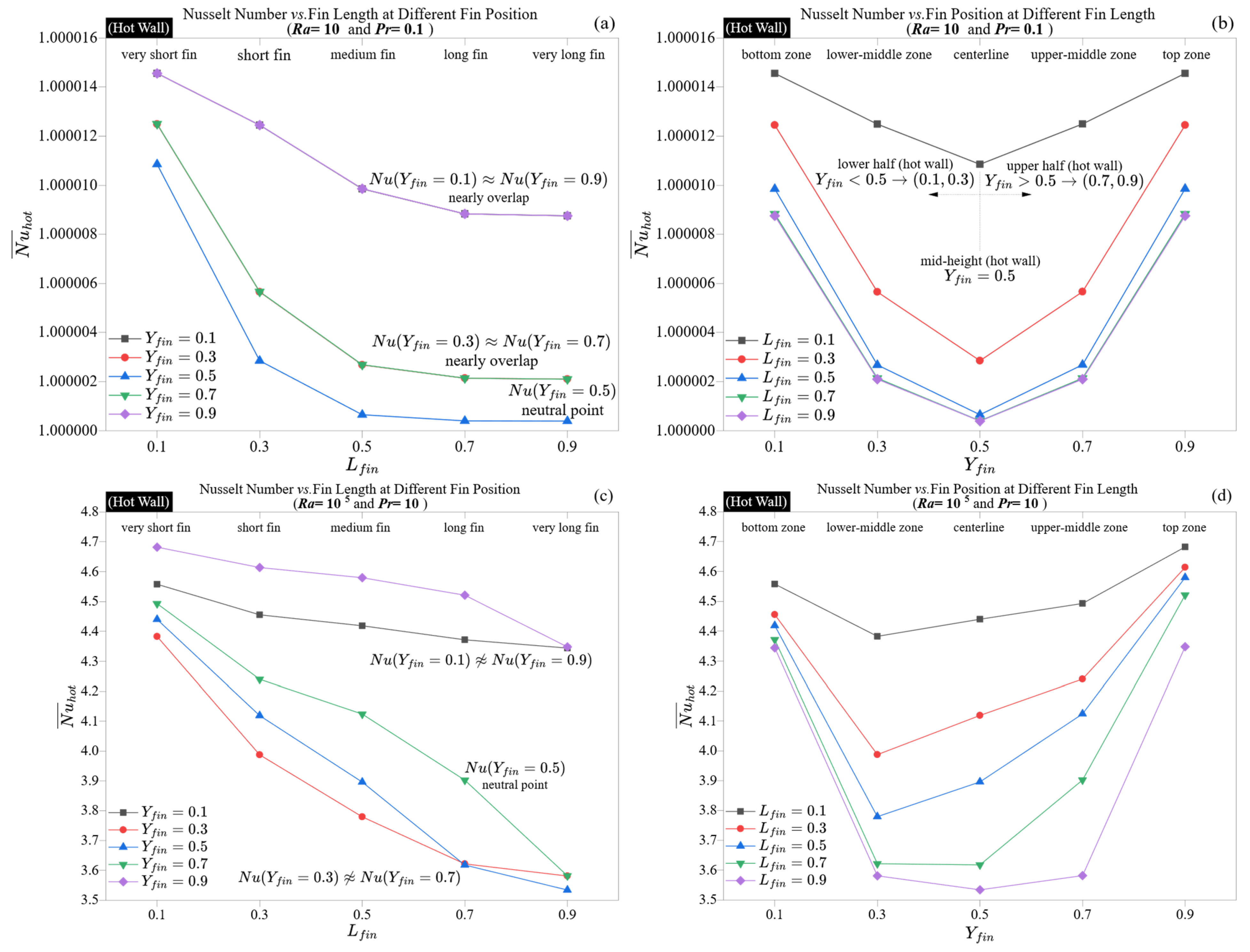
Figure 3 illustrates how the average Nusselt number varies with fin length and position at two extreme Rayleigh–Prandtl combinations:
Ra = 10,
Pr = 0.1, as shown in
Figure 3a,b, and
Ra = 10
5,
Pr = 10, as shown in
Figure 3c,d.
At
Ra = 10, the flow remains primarily diffusion-dominated with minimal convective circulation. As indicated in
Figure 3a,b, Nusselt numbers show slight variation across different geometric configurations, fluctuating within ±1.5 × 10
−5 around unity. The length of the fin has a negligible effect, and the vertical placement, from the bottom to the top wall, results in only slight curvature. Notably, the lowest values consistently appear when the fin is centered (position ≈ 0.5), implying that the wall-normal thermal gradient peaks at mid-height, rendering this area somewhat more responsive to obstruction, even without flow. These findings confirm that when conduction dominates transport, fin geometry behaves in a thermally passive manner.
In contrast, the situation changes significantly at
Ra = 10
5,
Pr = 10, where convective currents become dominant.
Figure 3c,d show that the length and placement of fins substantially impact hot-wall Nusselt numbers, which vary from 3.53 to 4.68. Short fins located near the top wall (e.g.,
Lfin = 0.1 at
Yfin = 0.9) achieve the highest heat transfer by aligning with the upward thermal plume near its detachment region. Conversely, long fins positioned centrally (e.g.,
Lfin = 0.9 at
Yfin = 0.5) significantly lower
by disrupting the core convective flow, effectively splitting the plume and flattening the vertical temperature gradient. These turning points in Nusselt number trends identify critical fin lengths at which the benefits of conduction are outweighed by plume disruption, particularly in high
Ra convection-dominated regimes.
The difference in alignment between bottom- and top-aligned fins is significant: fins placed higher enhance plume continuation, while those positioned lower can disrupt early development stages. This geometric selectivity is intensified by the high Prandtl number, which results in narrow thermal boundary layers, making the system particularly susceptible to vertical disturbances. At Ra = 105, the Nusselt number variation exceeds 30%, in sharp contrast to the less than 0.002% range at Ra = 10. This shift from geometric neutrality to thermal susceptibility exemplifies a critical regime change: in systems dominated by diffusion, fin geometry is irrelevant, whereas in convection-dominated scenarios, it is crucial.
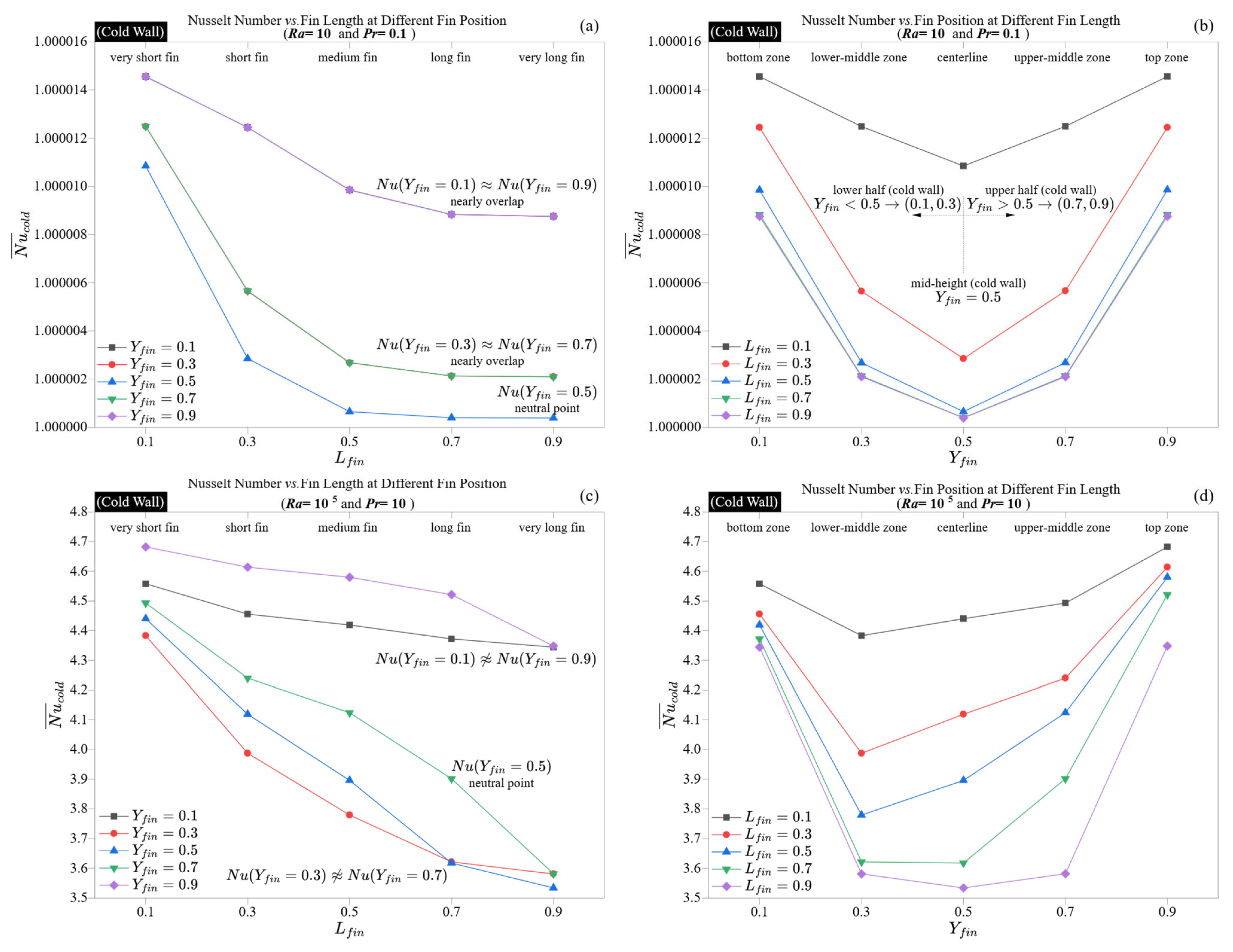
The cold wall contributes a complementary yet distinctly dynamic role to the thermal structure of natural convection within the cavity. In contrast to the hot wall, which uses fins to modulate thermal input, the cold wall focuses primarily on thermal absorption and wake recovery. Its Nusselt number trends therefore signify the downstream effects of plume interaction, flow recirculation, and thermal diffusion.
Figure 4 illustrates this behavior within the same Rayleigh-Prandtl boundaries applied earlier, at
Ra = 10,
Pr = 0.1 (
Figure 4a,b), and
Ra = 10
5,
Pr = 10 (
Figure 4c,d).
In the diffusive regime, as shown in
Figure 4a,b, the distribution of the Nusselt number closely resembles that of the hot wall, aligning to within six significant digits. This symmetry is due to the system being in a quasi-static state, where there is no significant flow; conduction solely governs the thermal field, resulting in nearly uniform temperature gradients within the cavity. Acceptable variations on either wall cause minimal disruption to isotherm curvature, resulting in identical thermal metrics on both sides. Consequently, there is an entirely symmetric conduction profile.
However, under high Rayleigh and Prandtl conditions, the behavior of the cold wall diverges subtly yet significantly from that of the hot wall.
Figure 4c,d illustrate that the average Nusselt number on the cold wall peaks at 4.68 and dips to a low of 3.53, closely reflecting the hot wall’s values but with slight positional variations. The cold wall’s response to the post-plume thermal wake, influenced by deflections caused by upstream fins, generates a delayed effect: fins obstructing hot wall plumes upstream inadvertently reduce convective intensity on the cold wall.
The trends illustrated in
Figure 4c indicate that longer fins typically lead to a decrease in Nusselt number, particularly at mid-height. In contrast, the cold wall shows somewhat greater tolerance to geometric obstructions compared to the hot wall. For example, the Nusselt number difference between
Lfin = 0.1 and
Lfin = 0.9 at central positions is generally smaller, usually under 0.9, while the hot side often experiences differences greater than 1.1. This implies that although fins on the hot wall influence core energy injection, the thermal energy that survives the convective path to reach the opposite boundary primarily dictates cold-wall transfer. This performance reduction at mid-height placement is specific to square cavities with symmetric vertical plumes; generalizing this effect to other geometries would require careful analysis of how plume dynamics shift with boundary shape and aspect ratio.
Position-dependent trends, as shown in
Figure 4d, further validate these findings. The lowest Nusselt number is again observed at mid-wall fin positions, but this minimum is less distinct. This subtle minimum results from diminished convective coherence: by the time the fluid hits the cold wall, it has become partially mixed and slowed down, which strengthens the thermal boundary layer against lateral fin disturbances. Additionally, the overall profile is somewhat flatter, indicating that the cold-wall Nusselt number is less concentrated and more shaped by the accumulated behavior upstream.
Unlike the hot wall, where the optimal fin placement enhances vertical alignment with buoyant flow, effective cold-wall designs focus on reducing wake interference and ensuring ample lateral access for incoming fluid. This highlights an important design distinction: thermal input and thermal recovery depend on different fin placement strategies, and no single fin geometry can optimize both types of walls simultaneously.
4.3. Spatial Control of Wall Heat Transfer: Role of Fin Length and Position
After establishing the regime sensitivity of fin performance, the analysis now shifts toward understanding how fin length and vertical position affect localized wall heat transfer. These spatial factors play a decisive role in shaping boundary layer behavior and energy distribution in naturally convecting enclosures.
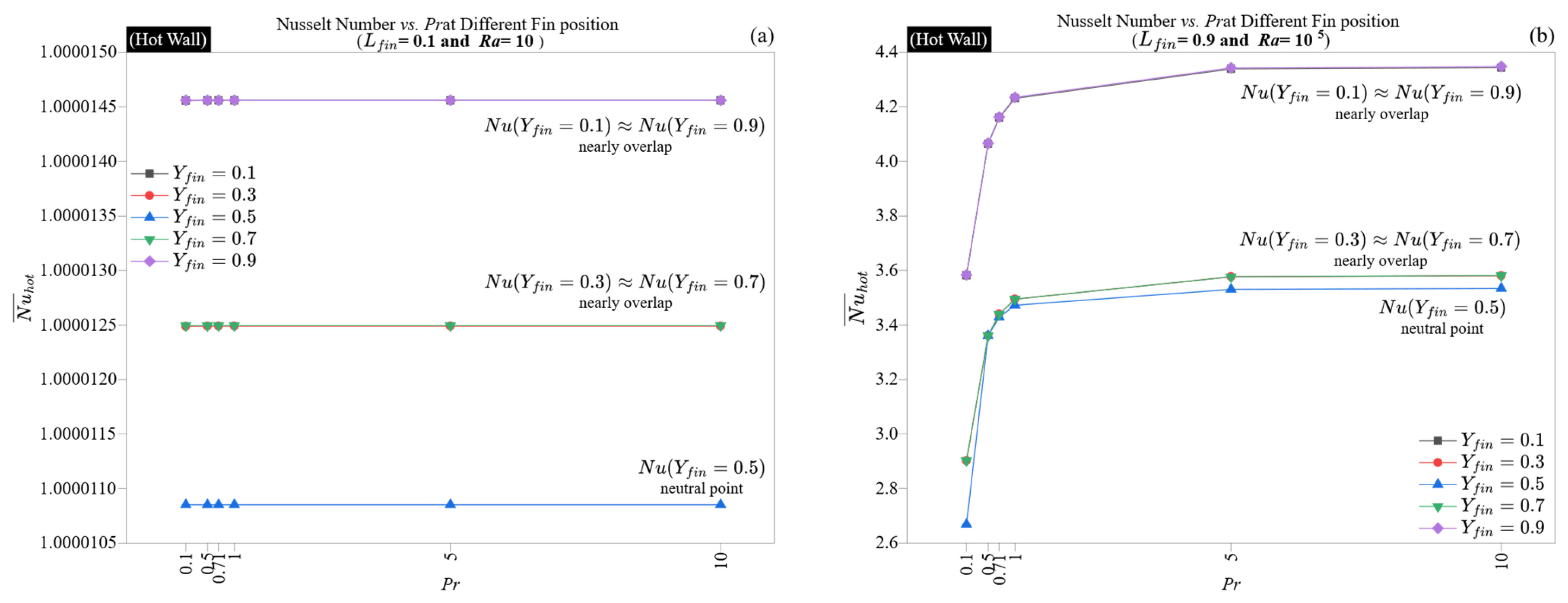
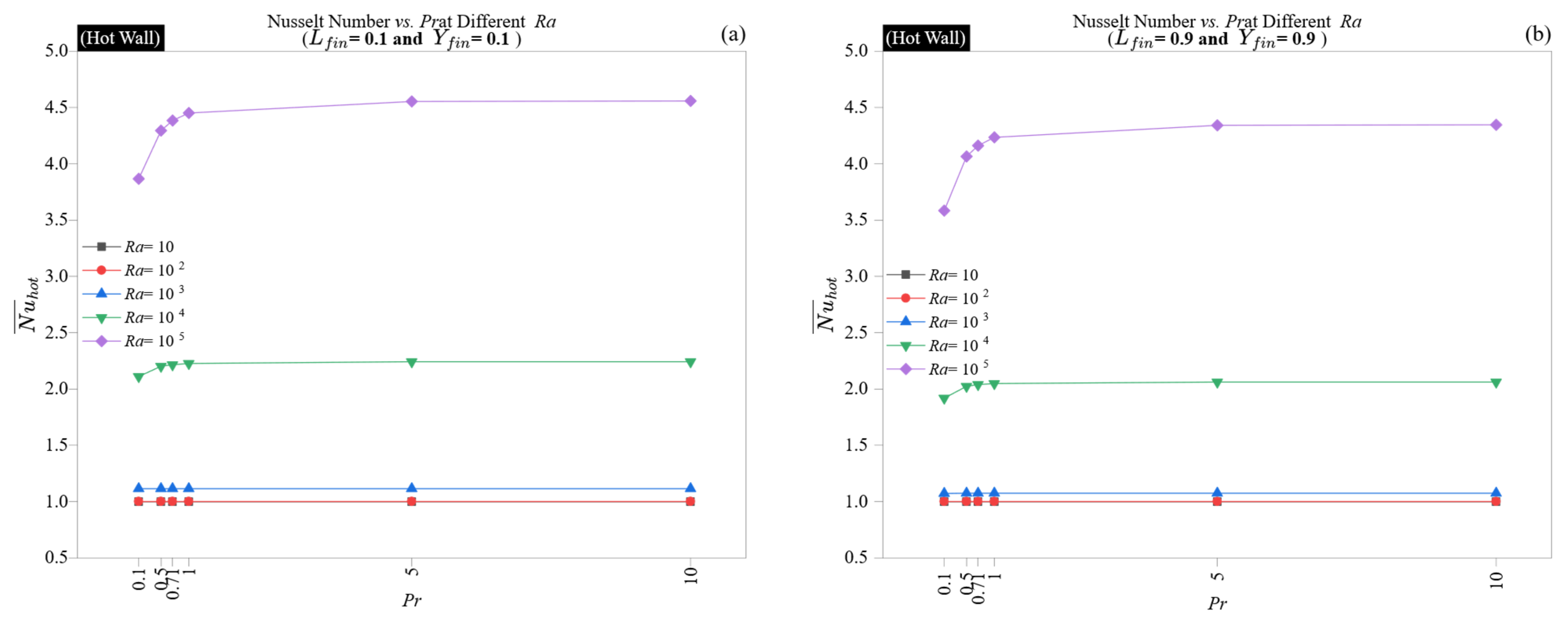
Figure 5 and
Figure 6 illustrate the influence of the Prandtl number on the thermal behavior of finned cavities, showing the average wall Nusselt number plotted against fin position for two sample fin lengths (
Lfin = 0.1 and
Lfin = 0.9) across six
Pr values, ranging from 0.1 to 10. In
Figure 5a and
Figure 6a, the diffusion-dominated regime (
Ra = 10) is depicted, whereas
Figure 5b and
Figure 6b focus on the convective regime (
Ra = 10
5).
When the Rayleigh number is low, changes in the Prandtl number have little effect.
Figure 5a and
Figure 6a show that all Nusselt numbers remain nearly constant and equal to their conduction limit (≈1.0000146 for short fins and ≈1.0000004 for long fins at the mid-position). This constancy emphasizes that, under minimal thermal forcing, the interaction between momentum and thermal diffusion is negligible; there is no flow or thermal stratification, and both walls maintain thermal symmetry, regardless of the Prandtl number. This consistency persists even with variations in fin position, reinforcing that, under pure conduction, the Prandtl number has no impact.
In the convective case at
Ra = 10
5, there is a clear and increasingly nonlinear sensitivity to the Prandtl number. Both walls exhibit this sensitivity, particularly the hot wall, as shown in
Figure 5b. As the Prandtl number increases from 0.1 to 10, the Nusselt number significantly rises, from 2.67 to 4.35 at mid-height (
Yfin = 0.5) and from 3.58 to 4.35 at the wall edges (
Yfin = 0.1 and 0.9). This pattern is closely linked to the thickness of the thermal boundary layer, which decreases as
Pr increases. Higher Prandtl numbers hinder thermal diffusion, resulting in steeper gradients near the walls and sharper plume boundaries, thereby enhancing wall-normal heat transport.
Interestingly, the advantages of high Pr are not evenly distributed throughout the wall. While all locations exhibit an increase in Nusselt number with Pr, the most significant improvement occurs at mid-wall positions, where fins impede flow. For example, at Yfin = 0.5 and Lfin = 0.9, the Nusselt number rises from 2.67 (Pr = 0.1) to 3.53 (Pr = 10), which is approximately a 32% increase. This indicates that fluids with a higher Prandtl number are more resistant to geometric disruptions, as their confined plumes are less prone to being flattened by nearby obstacles. Fins positioned at the top continue to yield the highest Nusselt number values across varying Pr, thanks to their placement in line with the terminal convective surge zone.
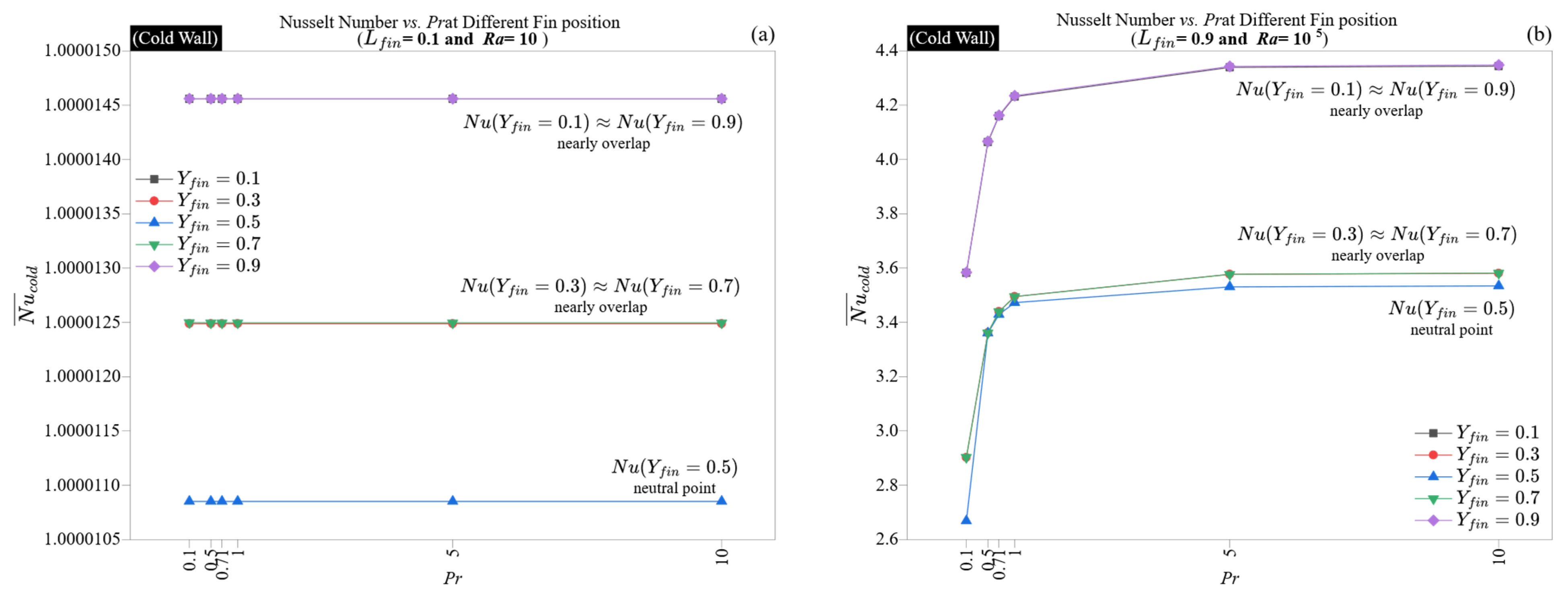
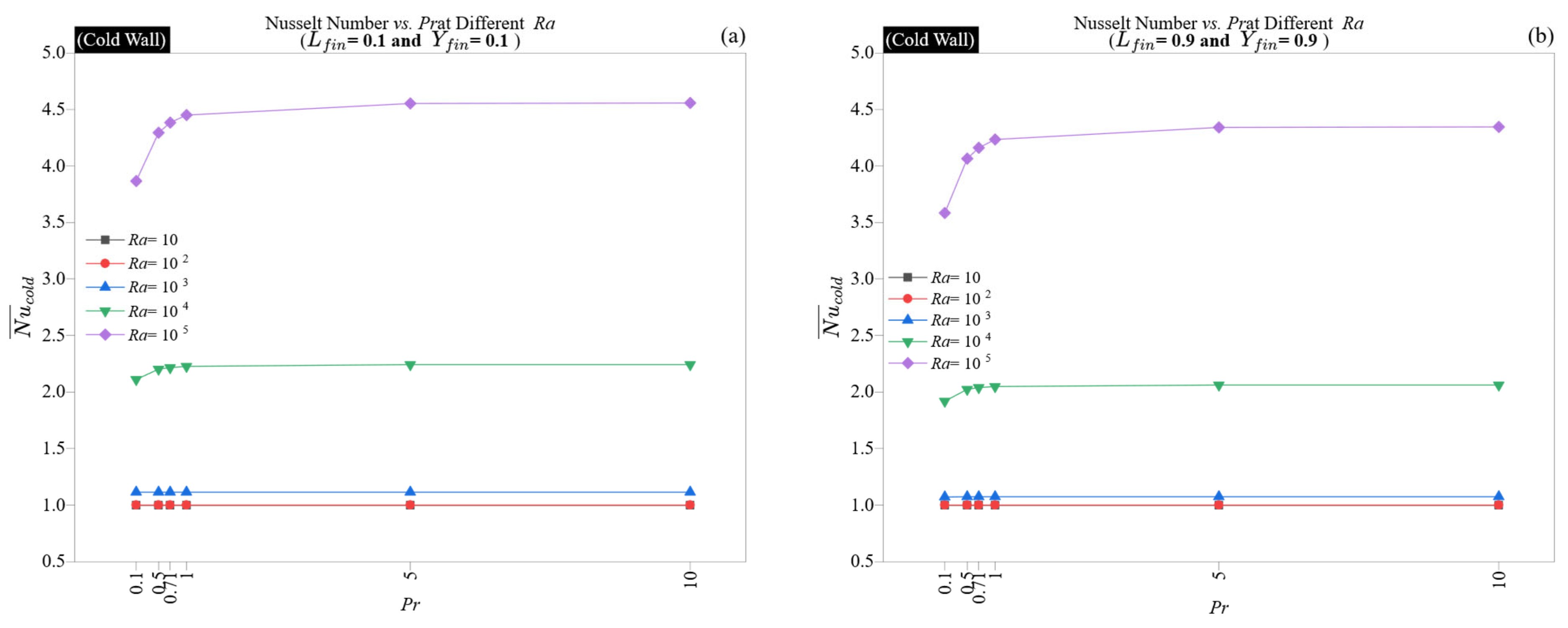
The cold wall reflects these trends with somewhat decreased sensitivity, as shown in
Figure 6b. The maximum Nusselt number still occurs near
Yfin = 0.9, and the values closely follow those of the hot wall. However, the gap between low and high
Pr cases is narrower, particularly for long fins, suggesting that thermal reception at the cold wall is more stable, influenced by the integrated plume structure formed upstream. This supports the notion that cold-wall performance results from downstream effects, determined more by convective quality than by initiation conditions.
This analysis shows that the Prandtl number is a secondary factor in conduction but a primary influence in convection. Its effect increases in geometrically confined areas and is particularly significant for fin designs that would typically hinder low-Prandtl flows. Therefore, the Prandtl number serves as a thermal “buffer,” improving the system’s capacity to dissipate heat even in less than ideal geometric configurations.
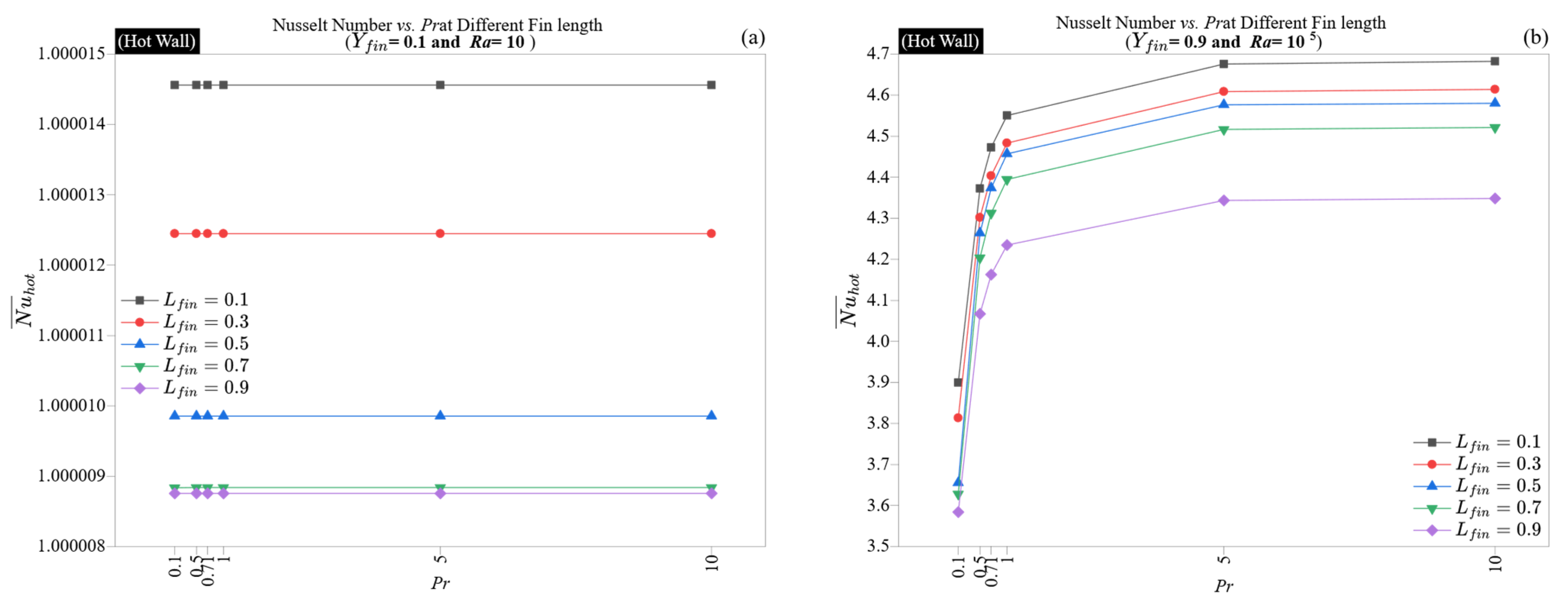
Figure 7 and
Figure 8 examine how the Prandtl number affects the distribution of the Nusselt number for fixed fin locations under two different Rayleigh conditions. This analysis focuses on the performance of five fin lengths (0.1–0.9 m) at the lower fin position (
Yfin = 0.1) for
Ra = 10, and the upper fin position (
Yfin = 0.9) for
Ra = 10
5, observing the Prandtl response at both thermal boundaries.
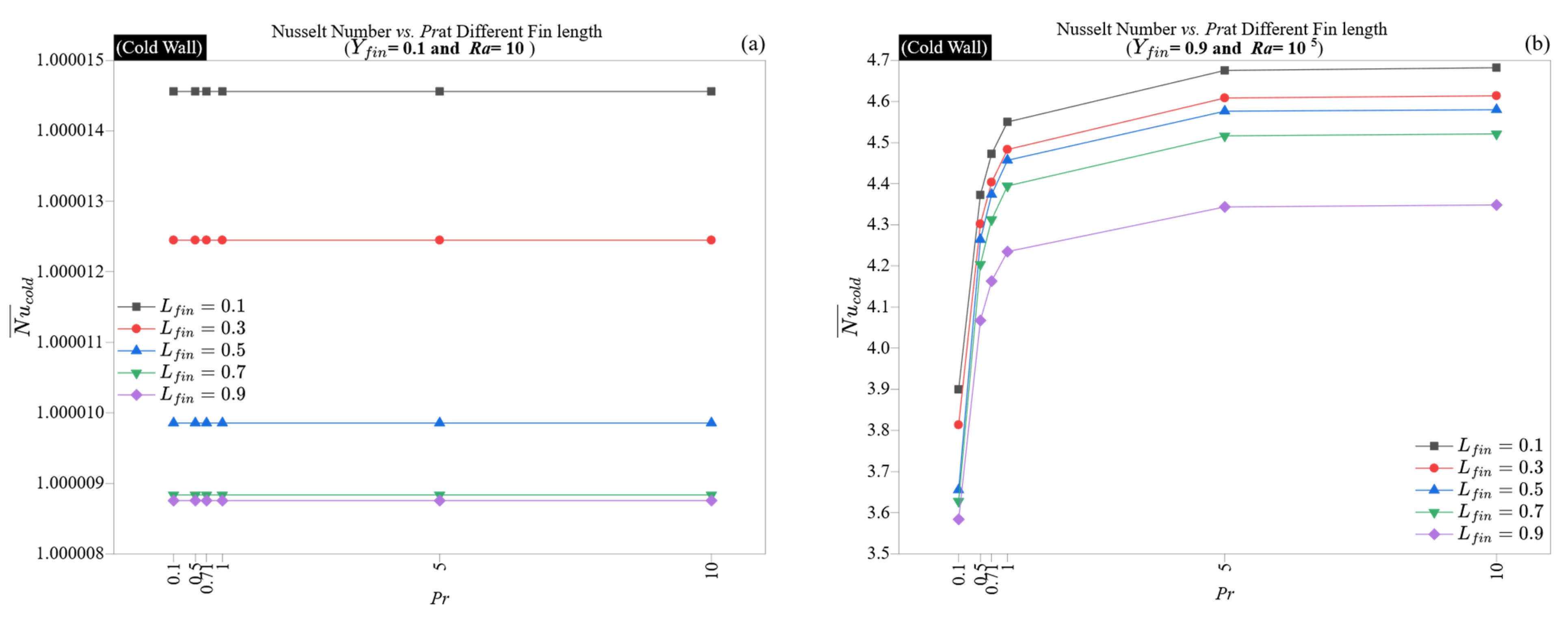
At a low Rayleigh number (
Ra = 10), conduction primarily governs the heat transfer regime
Figure 7a and
Figure 8a illustrate that the Nusselt number is constant across all Prandtl numbers and fin lengths, settling close to unity (1.0000146 for short fins and 1.0000088 for long fins). This lack of sensitivity indicates that, in still thermal conditions, changes in the relative diffusivities of momentum and energy do not affect the wall-normal gradient. Furthermore, the uniformity of the Nusselt number along both walls underscores the symmetry within the conduction regime. The slight decline in Nusselt number with longer fin lengths is merely geometric, not influenced by transport.
In contrast, at
Ra = 10
5 and
Yfin = 0.9, as shown in
Figure 7b and
Figure 8b, the Prandtl number has a significant impact on the results. For the hot wall, the Nusselt number increases from 3.58 (
Pr = 0.1) to 4.68 (
Pr = 10) for short fins, and from 3.65 to 4.58 for long fins. A comparable increase occurs on the cold wall, although with slightly lower absolute values. This improvement is nonlinear and levels off at higher
Pr values, demonstrating the contraction of the thermal boundary layer, which minimizes diffusive losses and enhances the rate of heat extraction from the wall.
A key observation is that the performance advantage of increasing Pr diminishes as the fin length increases. At Pr = 10, the Nusselt number decreases by approximately 0.33 units when transitioning from short to long fins (4.68 to 4.35), while at Pr = 0.1, this change results in a decrease of only about 0.3 units (3.90 to 3.58). This indicates that in high-Pr conditions, longer fins can more significantly hinder plume exit, thus moderating the convective advantage. The cold wall exhibits a similar suppression, reinforcing that long fins positioned near the plume termination point create a distributed drag that slightly counteracts the benefits from sharper boundary layers.
Overall, the findings suggest that with strong convective forcing, the Prandtl number plays a crucial role in thermal optimization, provided that fin placement allows access to plume-rich areas. Fins positioned near the top wall exhibit higher thermal gradients and effectively take advantage of Pr-induced enhancements, whereas longer fins may partially obscure this benefit. Therefore, for optimal system performance, using high-Pr fluids in combination with short, top-aligned fins creates a synergistic configuration that maximizes convective throughput.
4.5. Fin Position and Length Optimization Under Convective Flow Conditions
A focused analysis of fin position and length is presented here to determine optimal configurations in convection-dominated regimes. Emphasis is placed on identifying spatial arrangements that align with buoyant flow patterns and enhance heat transfer without introducing significant flow resistance.
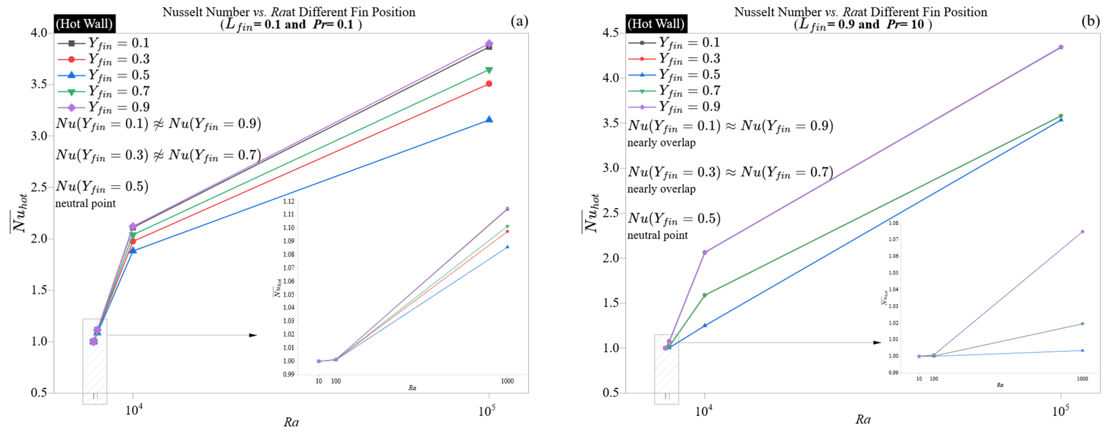
Figure 11 and
Figure 12 illustrate how the position of the fin affects wall heat transfer across five Rayleigh numbers (
Ra = 10 to 10
5) in two contrasting thermal configurations: a short fin at a low Prandtl number (
Pr = 0.1), as shown in
Figure 11a and
Figure 12a, and a long fin at a high Prandtl number (
Pr = 10), illustrated in
Figure 11b and
Figure 12b. These boundary cases were selected to demonstrate how thermal performance is spatially sensitive to fin placement in both conduction-dominated and convection-dominated scenarios.
At low Rayleigh numbers (Ra = 10), the Nusselt numbers for both the hot and cold walls stay close to one, independent of fin position or fluid characteristics. This consistent behavior, observed in all panels, underscores the prevalence of conductive transport and the lack of sensitivity of thermal gradients to geometric changes in these conditions.
As
Ra increases to 10
2 and 10
3, the Nusselt number starts to display spatial variation. In conditions with low Prandtl numbers and short fins, as shown in
Figure 11a and
Figure 12a, peak Nusselt number values are observed near the vertical boundaries (
Yfin = 0.1 and 0.9). In contrast, the centerline positioned fin (
Yfin = 0.5) consistently shows lower values. At higher Rayleigh numbers, the Nusselt number demonstrates a clear U-shaped dependence on fin position, especially in the
Pr = 10, long-fin scenario, as shown in
Figure 11b. For example, at
Ra = 10
5, the Nusselt number achieves a maximum of 4.35 at the cavity edges (
Yfin = 0.1 and 0.9) but falls to a minimum of 3.53 at the center (
Yfin = 0.5). This pattern indicates a gradual restriction of convective movement to the sidewalls, as the central plume becomes more obstructed by long fins, while outer positions retain better thermal accessibility. This trend is characteristic of natural convection systems with steep thermal gradients and slender boundary layers. The center-mounted fins disrupt the symmetry of the plume, causing stagnation and a decrease in the Nusselt number. In contrast, edge-aligned fins align with the main upwash and either contribute positively or remain neutral.
The pattern becomes more pronounced at
Ra = 10
4 and 10
5. In the high-
Pr, long-fin scenario (
Figure 11b and
Figure 12b, the hot wall displays a steep Nusselt number gradient from mid-position (
Yfin = 0.5:
≈ 3.53) to the bottom and top edges (
Yfin = 0.1 or 0.9:
≈ 4.34). This variation of 22.5% suggests that, in conditions of strong buoyancy and thin thermal layers, the placement of the fin is a crucial factor in controlling the outcome. By positioning a long fin at the centerline, a considerable obstruction is created for the vertical plume core, thereby decreasing the Nusselt number, even with favorable fluid characteristics. Conversely, the edge-aligned fin enhances the boundary layer’s curvature, facilitating localized extraction and maintaining the flow’s coherence.
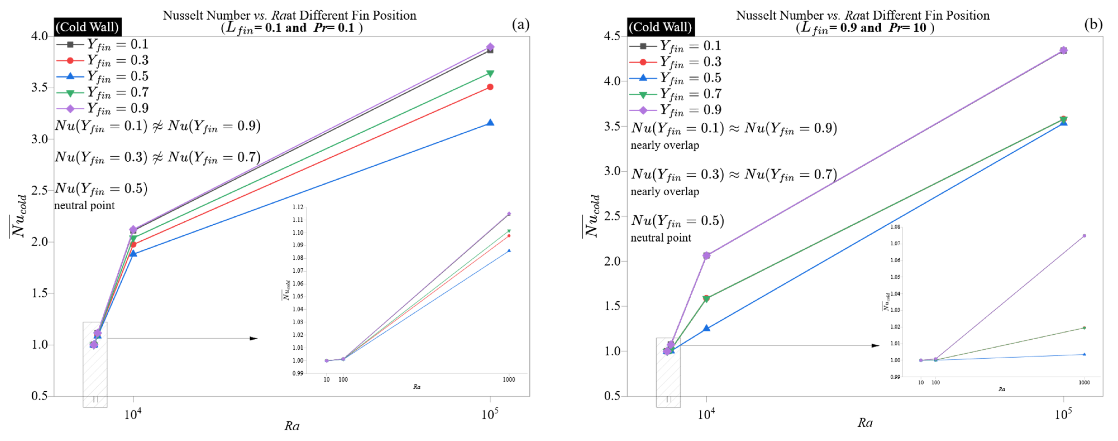
The cold wall (
Figure 12a,b) closely reflects these dynamics; however, the peak Nusselt number values are slightly lower, and the U-shaped trend is somewhat less pronounced. This asymmetry arises from the cold wall receiving pre-conditioned, upward-moving fluid. Although the upstream fin location still impacts the Nusselt number at the cold wall, its effect is somewhat moderated by the plume’s downstream inertia. Nevertheless, the correlation between hot and cold wall behavior, particularly at high
Ra and
Pr, illustrates that the fin position determines convective accessibility, independent of the thermal boundary orientation.
A significant nonlinear effect noted at high Ra is the reversal of geometric penalty in long-fin, high-Pr setups. Although longer fins usually reduce the Nusselt number due to flow obstruction, careful positioning near edges can completely recover or even surpass central values seen in short-fin, low-Pr configurations. For example, at Ra = 105, Pr = 10, and Yfin = 0.9, the hot wall reaches a of 4.35, exceeding the value of 3.87 that is obtained in the short-fin scenario at Pr = 0.1, Yfin = 0.1. This illustrates the crucial role of aligning high thermal gradients with low-obstruction geometries to enhance fin performance.
In conclusion, these findings indicate that the position of fins becomes a vital design factor only when convective transport is well established, particularly at Ra ≥ 103 and Pr ≥ 1. In such scenarios, fins located close to the wall boundaries (either top or bottom) take advantage of the flow’s natural curvature, whereas fins situated at mid-height may disrupt vertical consistency and diminish thermal efficiency. Consequently, the interaction between Pr, Ra, and Yfin establishes a geometric-performance framework for optimizing thermal design in natural convection systems.
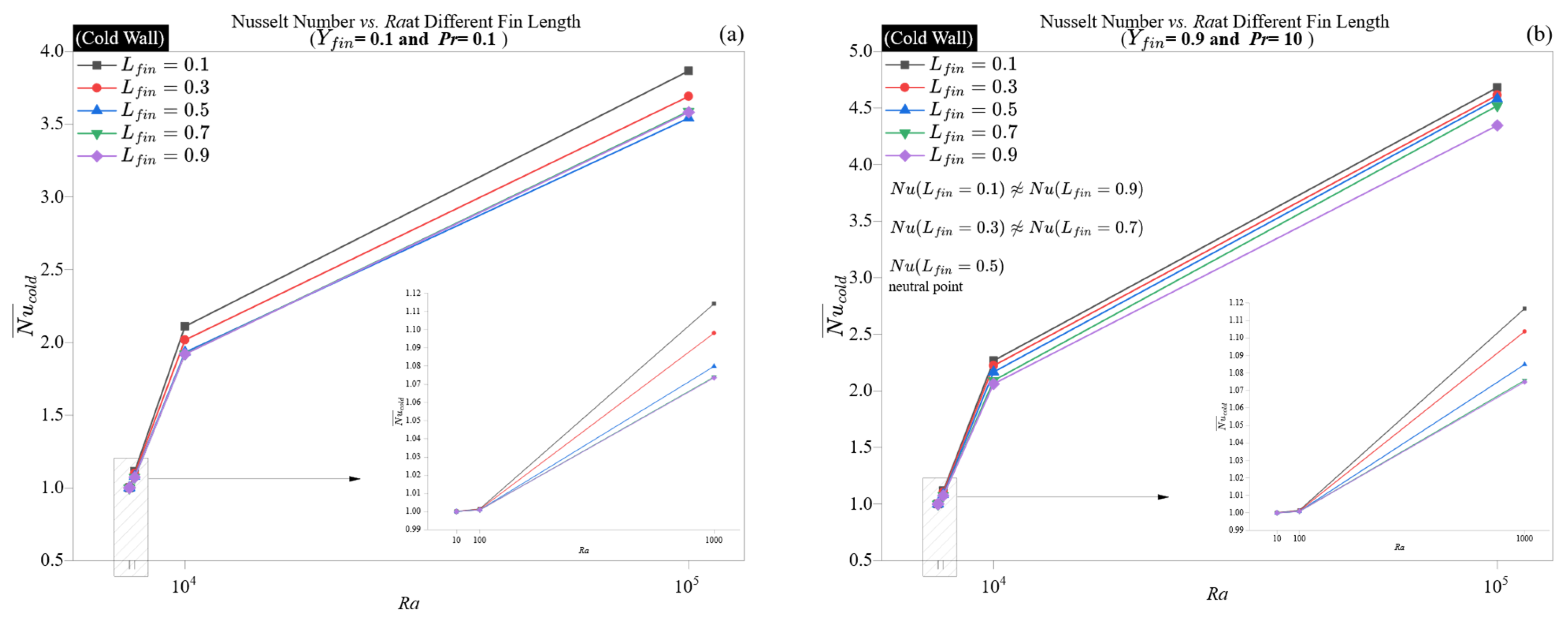
Figure 13 and
Figure 14 provide a detailed analysis of how fin length (
Lfin = 0.1 to 0.9) affects the Nusselt number on both hot and cold walls. This is examined at fixed fin positions and two thermophysical extremes: a low Prandtl number with a bottom-aligned fin (
Figure 13a and
Figure 14a) and a high Prandtl number with a top-aligned fin (
Figure 13b and
Figure 14b).
At a low Rayleigh number (Ra = 10), the Nusselt number stays close to one for all fin lengths, indicating that the system is primarily conduction-dominated and unaffected by geometric variations, regardless of thermal diffusivity. This is illustrated by the behavior of both hot and cold walls, where the Nusselt number changes by less than 0.001 between fin lengths of 0.1 and 0.9 for Pr = 0.1.
As
Ra increases to 100 and 1000, a non-monotonic pattern starts to appear, especially at
Pr = 10. For instance, in
Figure 13b, at
Ra = 1000, the Nusselt number for the hot wall peaks at shorter lengths (
Lfin = 0.1:
≈ 1.1168) and then decreases for intermediate lengths (
Lfin = 0.5:
≈ 1.0848), while it slightly recovers at the longest length (
Lfin = 0.9:
≈ 1.0748). This indicates that intermediate-length fins create a disruption zone that neither fully engages with nor avoids the primary convective streamlines, resulting in localized recirculation or thermal shadowing. Conversely, short fins cause minimal interference, whereas very long fins, situated near the thermal boundary (
Yfin = 0.9), align more effectively with the curvature of the boundary layer and prevent central blockage.
At elevated buoyancy forces (
Ra = 10
4 and 10
5), the Nusselt number increases significantly with
Ra across all fin lengths, with sensitivity to fin length becoming distinctly pronounced. In the high-
Pr scenario (
Figure 13b, the Nusselt number values range from 2.27 (
Lfin = 0.1) to 2.06 (
Lfin = 0.9) at
Ra = 10
4 and from 4.68 to 4.35 at
Ra = 10
5. This 7–10% reduction demonstrates how excessively long fins can hinder wall-normal momentum transfer, particularly in regions where the thermal plume rises most intensely. The behavior observed at the cold wall, as shown in
Figure 14b, exhibits a similar trend but with slightly reduced magnitudes, further confirming the secondary thermal influence of the downstream boundary.
Conversely, at
Pr = 0.1, the impact of fin length is significantly milder. In
Figure 13a, even when
Ra = 10
5, the Nusselt number only slightly decreases from 3.87 at
Lfin = 0.1 to 3.58 at
Lfin = 0.9. This suggests that in low-
Pr fluids, the thicker thermal boundary layers reduce the obstructive effects of fin geometry, enabling longer fins to work alongside vertical transport without causing significant flow bifurcations.
A detailed examination shows that mid-length fins (Lfin = 0.5) create local minima in the Nusselt number on both hot and cold walls, regardless of the Pr values. This indicates that Lfin = 0.5 disrupts the plume core most effectively, failing to skim the wall or deeply realign flow trajectories. This optimal point for disruption aligns with previous findings about fin position but is now emphasized in the axial (vertical) direction.
Overall, the findings indicate that fin length is a crucial design factor mainly at intermediate-to-high Rayleigh numbers and elevated Prandtl numbers. In these scenarios, long fins can cause significant interference if they are not properly placed. In contrast, in low-Pr fluids or under low Rayleigh number conditions, thermal diffusion prevails, reducing the effects of geometrical extension.


