Review

A Review of New Technologies in the Design and Application of Wind Turbine Generators

by
Pawel Prajzendanc
1,* and
Christian Kreischer
2
1
Faculty of Mechatronics and Electrical Engineering, Maritime University of Szczecin, Willowa 2, 71-650 Szczecin, Poland
2
Electrical Machines and Drive Systems, Helmut Schmidt University/University of the Federal Armed Forces, 22043 Hamburg, Germany
*
Author to whom correspondence should be addressed.
Energies 2025, 18(15), 4082; https://doi.org/10.3390/en18154082
Submission received: 18 June 2025 / Revised: 21 July 2025 / Accepted: 29 July 2025 / Published: 1 August 2025
(This article belongs to the Special Issue Advancements in Marine Renewable Energy and Hybridization Prospects)

Abstract

The growing global demand for electricity, driven by the development of electromobility, data centers, and smart technologies, necessitates innovative approaches to energy generation. Wind power, as a clean and renewable energy source, plays a pivotal role in the global transition towards low-carbon power systems. This paper presents a comprehensive review of generator technologies used in wind turbine applications, ranging from conventional synchronous and asynchronous machines to advanced concepts such as low-speed direct-drive (DD) generators, axial-flux topologies, and superconducting generators utilizing low-temperature superconductors (LTS) and high-temperature superconductors (HTS). The advantages and limitations of each design are discussed in the context of efficiency, weight, reliability, scalability, and suitability for offshore deployment. Special attention is given to HTS-based generator systems, which offer superior power density and reduced losses, along with challenges related to cryogenic cooling and materials engineering. Furthermore, the paper analyzes selected modern generator designs to provide references for enhancing the performance of grid-synchronized hybrid microgrids integrating solar PV, wind, battery energy storage, and HTS-enhanced generators. This review serves as a valuable resource for researchers and engineers developing next-generation wind energy technologies with improved efficiency and integration potential.

1. Introduction

Due to the increasing adoption of advanced technologies such as electromobility, artificial intelligence, and other innovative solutions, the demand for electrical energy continues to grow steadily. The development of electric vehicles and their charging infrastructure is leading the transportation sector to rely more heavily on electric power. Modern transportation solutions, including high-speed electric railways, autonomous vehicles, and the emergence of electric aircraft, are also contributing significantly to rising energy consumption [1,2,3].
At the same time, there is rapid development in the fields of artificial intelligence (AI) and data centers, which handle an ever-growing volume of information, process advanced AI algorithms, and support the operation of cloud-based digital services. Another significant factor is the rise of automation and the Internet of Things (IoT). Smart buildings, energy management systems, and increasingly sophisticated everyday devices require constant access to electrical power. In the industrial sector, the impact of the Fourth Industrial Revolution is evident—robotization, digital process control, and the integration of advanced technologies into manufacturing processes are substantially increasing energy demand [4,5].

1.1. Wind Energy and the Need for New Technologies

Modern energy generation systems focus on efficiency improvement, loss reduction, and emission mitigation. Contemporary power engineering relies on a diverse mix of energy sources, including fossil fuels, nuclear power, hydroelectricity, solar, and wind energy. The structure of energy sources used for electricity production in a given country or region depends on various factors such as resource availability, climate policy, production costs, and energy security. Countries rich in natural resources—such as coal or natural gas—tend to maintain reliance on fossil fuels for longer periods, while nations with ambitious climate goals invest in renewable energy sources and emerging technologies. The global trend in energy development is moving toward decarbonization, signifying a gradual transition away from fossil fuels and an increasing share of clean energy sources, such as wind, solar, nuclear power, and hydrogen [6,7].
Wind energy, in particular, is playing an increasingly significant role in the transformation of the energy sector, as it represents a renewable and environmentally friendly power source. Wind energy systems utilize wind turbines to convert the kinetic energy of the wind into mechanical energy, which is then transformed into electrical energy through generators. Modern wind turbines achieve progressively higher efficiency thanks to the use of advanced materials, aerodynamic optimization of blade design, and intelligent control systems that adapt turbine operation to changing atmospheric conditions [8,9].
Wind energy offers numerous advantages, including zero CO2 emissions, low operating costs, and significant scalability potential. It can be deployed both onshore and offshore, with offshore sites typically benefiting from more favorable wind conditions. There is a consistent trend toward increasing turbine height and rotor diameter, which enhances energy output. However, the development of wind energy also faces several challenges, such as the variability of power generation depending on weather conditions, manufacturing capacity, supply chain constraints, the need for expansion of electrical grid infrastructure, and its impact on landscapes and natural ecosystems [10].
Modern energy storage systems, including those utilizing hydrogen as an energy carrier, have the potential to significantly enhance the flexibility and stability of power grids. They enable efficient balancing of supply and demand and facilitate the integration of renewable energy sources such as wind and solar power. Energy storage allows for improved management of the intermittency of renewable energy sources, increasing grid inertia. Hydrogen, in particular, can serve both as a fuel and as an energy storage medium within a zero-emission energy system. Technological advancements and increasing investments in energy storage and smart grid infrastructure are contributing to the growing share of wind power in the global energy mix. Wind energy is a key component of decarbonization strategies and energy security frameworks, and its importance is expected to continue rising in the coming decades [11,12].
The kinetic energy of wind, resulting from the movement of air masses, can be converted into mechanical energy and subsequently into electrical energy using wind turbines [13]. The power available in the wind is given by the following equation:
P w = 0.5 ρ A υ 3
where ρ is the air density, A is the swept area of the rotor, and υ is the wind velocity. The cubic dependence on wind speed highlights the importance of appropriate turbine siting and optimized aerodynamic design.
However, not all the kinetic energy contained in the wind can be converted into useful power. The efficiency of this energy conversion is described by the power coefficient C p , a dimensionless parameter defined as the ratio of the actual power extracted by the turbine to the total power available in the wind stream. According to Betz’s law, the theoretical maximum value of C p is 16/27, indicating that no wind turbine can capture more than 59.3% of the kinetic energy in the wind. In practice, modern wind turbines typically achieve C p values ranging from 0.35 to 0.45, depending on the rotor design (Figure 1), operating conditions, and control strategies [14].
The increasing energy demand, coupled with the need for high efficiency, compactness, and reduced maintenance—especially in offshore environments—has accelerated the evolution of wind turbine generator technologies. Traditional synchronous and asynchronous generators, while proven and reliable, often fall short in terms of scalability, mass-to-torque ratio, and energy losses at variable speeds. These limitations, together with the trend towards direct-drive architectures and larger turbine ratings, have spurred the development of advanced generator designs. Among them, permanent magnet synchronous generators (PMSGs), superconducting machines, and axial-flux topologies offer promising solutions that align with the technical, economic, and environmental requirements of next-generation wind energy systems. The following sections present a systematic review of these generator types and the technological rationale behind their adoption.

1.2. Requirements for Generators Used in Wind Turbines

Generators used in wind turbines must meet a range of technical and operational requirements to ensure reliable, efficient, and long-term performance under variable environmental conditions. Above all, they must exhibit high efficiency, as even minor energy losses can significantly reduce the overall effectiveness of a wind power plant. Additionally, they must be capable of operating under variable rotor speeds to keep the tip speed ratio constant for different wind speeds. This necessitates the use of technologies that allow flexible adjustment of generator operating parameters. Another critical requirement is resilience to harsh weather conditions, including fluctuating temperatures, humidity, precipitation (rain or snow), and salinity in the case of offshore installations. Generators must be protected against corrosion and equipped with robust electrical insulation to endure years of operation in demanding environments. As a result, these systems incorporate materials with high mechanical strength and employ efficient cooling mechanisms to prevent overheating of windings and bearings [15,16,17].
Another important aspect is the generator’s compatibility with the power grid, which entails meeting standards for power quality, voltage stability, and frequency regulation. Modern wind turbine generators often operate in conjunction with power electronic systems, such as inverters, which enable the conversion of alternating current and the adjustment of output parameters to match grid requirements. Moreover, generators must exhibit high reliability and low maintenance demands, as access to wind turbines—particularly offshore—is challenging and costly. As a result, brushless and gearless designs with a minimal number of wear-prone mechanical components are commonly used. Additionally, condition monitoring systems are integrated to enable early fault detection and facilitate predictive maintenance [18,19,20,21].
Ultimately, the selection of a specific generator type depends on the turbine design and the chosen power regulation strategy.
While numerous reviews have addressed wind turbine generator technologies, they often focus on individual machine types, specific applications, or component-level parameters. In contrast, this review provides a comprehensive comparative analysis of synchronous and asynchronous generators, axial-flux machines, and superconducting generators in the context of modern low-speed, high-power wind turbines. This work integrates aspects of electromagnetic performance, structural mass, cooling strategies, material constraints, TRL status, and offshore applicability—offering a consolidated, system-level perspective for next-generation wind energy systems. To better illustrate the maturity of each technology discussed in this study, their corresponding TRLs are summarized in Table 1.

2. Types of Generators in Wind Turbines

2.1. Synchronous Generators

Synchronous generators (SG) used in wind turbines are key components in the conversion of wind’s kinetic energy into electrical power. They are characterized by a constant rotor angular velocity relative to the frequency of the generated voltage, meaning the output frequency is directly tied to the turbine’s rotational speed. While the use of synchronous generators in wind energy systems offers numerous advantages, it also necessitates advanced control systems and power electronics.
Permanent Magnet Synchronous Generators (PMSGs), in particular, feature permanent magnets (PMs) mounted on the rotor, eliminating the need for excitation windings and external Direct Current (DC) excitation systems. As a result, these machines offer high efficiency, and high power density and reliability, due to the absence of excitation current losses. Their compact design reduces overall weight and enhances energy efficiency. However, the technology also has drawbacks, primarily the relatively high cost and resource limits of rare-earth PMs, especially those made from materials such as neodymium or dysprosium [22,23,24]. Current research on permanent magnets focuses both on developing new manufacturing techniques that consider production time, cost, and enhanced magnetic properties [25], and on exploring alternative materials such as manganese bismuth (MnBi), samarium iron nitride (Sm2Fe17N3), and iron nitride (Fe16N2) [26,27,28].
Brushless Direct Current (BLDC) generators are PM synchronous machines widely used in small-scale wind turbines, particularly in off-grid and hybrid systems. Due to the absence of brushes, they offer high efficiency, enhanced reliability, and low cogging torque, enabling turbine startup under low wind conditions. Their design supports DD configurations, eliminating the need for mechanical gearboxes. However, one of the main drawbacks is the high cost of rare-earth magnets, such as those made from neodymium. Additionally, BLDC generators require advanced power electronics for control and energy conversion. These generators typically operate at low voltage, which limits their efficiency for long-distance energy transmission. Nonetheless, they remain a popular choice for micro-installations due to their ease of maintenance and good performance under variable wind conditions. Research has shown that with proper design and control strategies, torque ripple can be minimized and output power quality significantly improved [29,30,31].
Electrically Excited Synchronous Generators (EESGs) utilize an excitation winding on the rotor, powered by direct current supplied through slip rings and brushes or via a brushless excitation system. This configuration enables active control of the magnetic flux, offering greater flexibility and precise regulation of generator operating parameters. One of the key advantages of EESGs is their reduced reliance on expensive magnetic materials, which can positively impact production costs and supply chain stability. However, a notable drawback of this design is its higher operational complexity due to the presence of the excitation system and rotating components that require periodic maintenance [32,33,34].
The most important advantages, disadvantages, and challenges of synchronous generators used in wind turbines are presented in Table 2.
Synchronous generators are predominant in modern wind turbines, particularly in high-power units (>3 MW) deployed both onshore and offshore. In offshore installations, PMSGs are often preferred due to their high efficiency, reliability, and the absence of wear-prone components such as brushes.
Although various mechanical gearbox configurations are used in conjunction with these generators, recent studies and publications increasingly highlight the adoption of DD systems (without mechanical gearboxes). These configurations eliminate energy losses associated with gearbox operation and significantly reduce the risk of mechanical failure [35].
Thanks to the rapid advancement of power electronics and new structural materials, synchronous generators are becoming increasingly efficient and are playing a pivotal role in the energy transition toward renewable energy sources.

2.2. Asynchronous Generators

Asynchronous generators, also known as induction generators, are widely used in wind turbines, particularly in older and smaller-scale units. Their popularity stems from their simple construction, high reliability, and low operational costs. Unlike synchronous generators, they do not require a separate excitation system, as the magnetic field in the rotor is generated through electromagnetic induction from the rotating magnetic field of the stator [36].
Squirrel Cage Induction Generators (SCIGs) utilize a rotor in the form of a squirrel cage, making them structurally very simple, durable, and cost-effective to manufacture. However, they require direct connection to the power grid, sometimes with the use of external capacitors to provide the needed reactive power, which limits their operational flexibility. Furthermore, a full power inverter can be used to decouple the grid from the generator and to allow variable rotor speeds. Additionally, they exhibit relatively low efficiency and a very limited capability to operate under variable rotor speeds. As a result, SCIGs are increasingly being phased out in modern wind turbines, particularly in higher-power applications [37,38].
Doubly Fed Induction Generators (DFIGs) are equipped with a rotor winding that is powered through a power electronic converter. This configuration enables efficient control of both the generator’s rotational speed and output power. As a result, DFIGs can operate over a wide range of wind speeds (±30% relative to synchronous speed), significantly enhancing the overall energy efficiency of the system.
Since the converters in DFIG systems handle only a fraction of the total power (typically 30%), they are a cost-effective solution for wind turbines in the 1.5 MW to 5 MW range. This design offers an optimal balance between operational flexibility and installation cost, making DFIGs a widely adopted choice in medium- to large-scale wind turbine applications [39,40].
The most important advantages, disadvantages, and limitations of asynchronous generators used in wind turbines are presented in Table 3.
Squirrel cage asynchronous generators were widely used in earlier generations of wind turbines; however, their market share is currently declining in favor of synchronous generators, particularly those equipped with PMs. Nevertheless, DFIGs still dominate in medium- and large-scale wind turbines (1.5–5 MW), especially in grid-connected systems where reactive power control is essential.
In modern offshore systems, asynchronous generators—often of the squirrel cage type—are connected to the grid via a full-scale back-to-back converter system and an HVDC (High Voltage Direct Current) transmission line. This configuration allows for independent control of active and reactive power, while electrically decoupling the generator from direct grid influence. As a result, system stability is enhanced, and the turbine is capable of operating efficiently over a wide range of rotational speeds [41,42].
Modern wind turbine designs increasingly aim to eliminate mechanical gearboxes through the adoption of DD systems, which has led to a gradual decline in the use of asynchronous generators. Nevertheless, due to their proven technology and lower cost, asynchronous generators continue to be employed in various projects—particularly where simplicity, reliability, and low capital investment are key priorities.

3. Low-Speed Generators

DD systems are used in modern wind turbines, where the generator is directly coupled to the rotor shaft, which eliminates the need for a mechanical gearbox. This design reduces the number of moving parts, resulting in increased reliability and lower operating and maintenance costs [43,44].
In conventional wind turbines, mechanical gearboxes are used to increase the rotational speed of the rotor shaft (e.g., from 10–20 rpm to 1500 rpm), enabling standard generators to operate efficiently. In DD systems, however, the generator operates at low rotational speeds, matching those of the turbine rotor. To achieve efficient energy conversion without the need for speed amplification, these systems utilize large-diameter, multi-pole generators capable of producing electrical power effectively at low rotational speeds [45,46].
The most important advantages, disadvantages, and challenges of DD systems are presented in Table 4.
In wind turbines utilizing DD systems, PMSGs are most commonly employed.

4. Superconductivity Theory and Its Application in Generators

4.1. Superconductivity Phenomenon—Basic Principles

Superconductivity is a physical phenomenon characterized by the complete disappearance of electrical resistance and the expulsion of magnetic fields from the interior of a material (the Meissner effect).
Superconductivity occurs only under specific conditions, which are defined by three critical parameters: the critical temperature T C , the critical magnetic flux density B C and the critical current density J C . Exceeding any of these parameters causes the material to transition from the superconducting state to a normal conducting state, resulting in the loss of its distinctive properties—namely, zero electrical resistance and the Meissner effect [47,48,49].
The critical temperature T C is the maximum temperature below which a material can exhibit superconducting behavior. Below this threshold, electrons in the superconductor form Cooper pairs, which move in a coordinated manner without energy dissipation, resulting in zero electrical resistance. Based on the critical temperature, superconductors are classified into two categories: Low-Temperature Superconductors (LTS) and High-Temperature Superconductors (HTS).
The critical magnetic flux density B C defines the maximum magnetic flux density a superconductor can withstand before losing its superconducting properties. In Type I superconductors, this critical flux density is relatively low, and exceeding it results in a complete suppression of superconductivity. In contrast, Type II superconductors exhibit two critical magnetic flux densities: B C 1 , above which magnetic flux begins to penetrate the material in the form of Abrikosov vortices, and B C 2 , beyond which superconductivity is fully destroyed. This property allows Type II superconductors to operate under strong magnetic flux densities, making them suitable for applications such as superconducting magnets and electrical machines with HTS excitation [50,51].
The critical current density J C represents the maximum current a superconductor can carry without losing its superconducting state. When the current density exceeds J C , the Lorentz force acting on the magnetic flux vortices causes them to move, leading to energy dissipation and a rise in resistance. This limitation poses a significant challenge in practical applications such as superconducting transmission lines and high-current magnets [52].
Contemporary research focuses on optimizing the material and structural properties of superconductors to increase their critical current density, minimize AC losses, and improve performance stability under dynamic electromagnetic, thermal, and mechanical conditions [53,54,55,56].

4.2. Types of Superconductors

As previously mentioned, superconductors can be categorized into two main classes: LTS and HTS. These groups differ in terms of their critical properties, constituent materials, and cooling requirements.
LTS refers to materials that transition into the superconducting state at temperatures below 30 K. The most well-known representatives of this group are NbTi (niobium–titanium) (9 K) and Nb3Sn (niobium–tin) (18 K). LTS superconductors require cooling with liquid helium (4.2 K), which increases operational costs. Despite this, they are widely used in fields such as magnetic resonance imaging (MRI), particle accelerators, and magnets for nuclear fusion. Their main advantage lies in the well-established manufacturing technologies and relatively low energy losses under constant magnetic field conditions.
HTS, discovered in the 1980s, exhibit superconductivity at significantly higher temperatures—often above 77 K—allowing for cooling with liquid nitrogen, which is considerably less expensive than liquid helium. The most commonly used materials in this class include Bi2Sr2Ca2Cu3O10 (BSCCO-2223) (108 K) and YBa2Cu3O7 (YBCO) (92 K). HTS materials are capable of sustaining higher critical currents and magnetic fields, making them highly promising for applications in electrical machines, superconducting power cables, and high-efficiency energy systems.
However, HTS also face significant challenges, such as increased Alternating Current (AC) losses and difficulties in manufacturing long-length conductors. These limitations currently restrict their widespread commercial deployment, particularly in large-scale or cost-sensitive applications.
Magnesium diboride (MgB2) is a lightweight, low-cost, and technologically simple superconducting material with a critical temperature of approximately 39 K. This enables its operation under moderate cryogenic conditions, such as those provided by liquid hydrogen systems. Although MgB2 has a lower TC than HTS materials, it offers advantages in terms of structural simplicity, ease of wire fabrication, and lower density, making it particularly attractive for applications where weight reduction is a critical design factor [57]. Modern manufacturing methods for MgB2, such as Laser Powder Bed Fusion (L-PBF) combined with Spark Plasma Sintering (SPS) and high-temperature centrifugal synthesis (SHS-C), significantly expand the engineering potential of this superconductor. L-PBF enables precise shaping of complex geometries, which is essential in designs requiring integration of superconducting material with lightweight components of irregular shapes. When followed by SPS, this process yields dense and durable structures with high phase purity and a superconducting transition temperature close to 38 K. This combination of technologies supports the production of components with optimized mechanical and electrical properties, suitable for use in electromagnets, drives, and lightweight energy systems [58]. On the other hand, the SHS-C method allows for extremely rapid (millisecond-scale) synthesis of MgB2 while simultaneously densifying the material under strong centrifugal forces. This makes it possible to obtain high-density, low-porosity samples with good superconducting properties in a very short time and with low energy consumption. The technique is particularly promising for large-scale production of simple MgB2 shapes, where efficiency and low unit cost are crucial [59]. Both methods offer unique advantages: the first provides design flexibility and high material quality, while the second offers speed and process simplicity. Together, they reflect the dynamic development of MgB2 processing technologies and its growing application potential.

4.3. Use of Superconductors in Generators

The application of superconductors in wind turbine generators enables a significant reduction in the mass and volume of the machines, which is particularly critical for offshore turbines. Due to their ability to generate stronger magnetic fields than conventional copper windings, superconducting generators can be designed to be more compact and lighter. This mass reduces mechanical loads and decreases the structural costs associated with the tower and foundation, which, in the case of large offshore turbines, can lead to substantial lifecycle cost savings. Another major advantage of superconducting generators is their superior energy efficiency. The absence of electrical resistance in superconducting windings eliminates Joule losses, allowing for efficiencies exceeding 98%—significantly higher than those achieved by conventional synchronous generators with PMs or copper windings. As a result, a greater proportion of wind energy can be converted into electrical energy, improving the overall efficiency of the renewable power generation system, especially in part load situations [60,61].
A comprehensive review of HTS materials and their potential industrial applications, including large-scale energy systems and electric generators, has been provided by Shimoyama and Motoki [62]. The authors discuss the development of ReBCO tape technology, its mechanical and electrical properties, challenges related to fabrication and cryogenic cooling, and existing commercial use cases. This publication offers an up-to-date overview of HTS material maturity and serves as a valuable reference for assessing their applicability in modern direct-drive wind turbine generators.
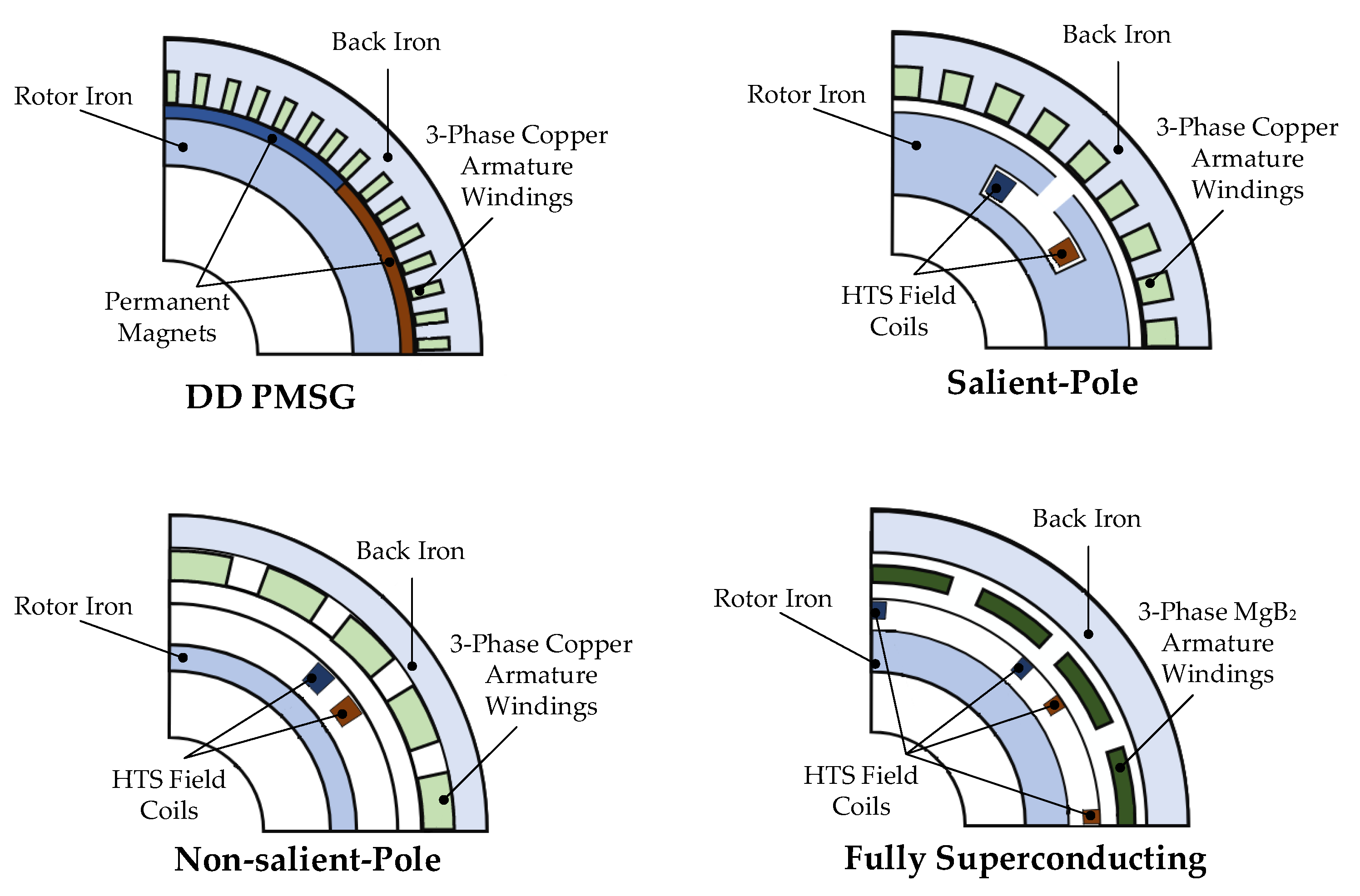
The use of superconducting technology also enables the elimination of mechanical gearboxes, simplifying generator design. Traditional wind turbines often rely on gearboxes to increase the rotational speed of the generator, which introduces additional mechanical losses, noise, and maintenance costs. Superconducting generators, by contrast, can operate efficiently at low rotational speeds, allowing for DD configurations that improve system reliability and reduce operational expenses. A comparison between the DD PMSG and various generator designs incorporating superconducting materials is presented in Figure 2.
Moreover, superconducting generators offer enhanced operational flexibility in terms of power and torque control. Due to the ability to achieve higher magnetic flux densities in the air gap, these machines can operate more stably under variable wind speed conditions, thereby improving the quality of power delivered to the grid and reducing voltage fluctuations. This is especially important for the integration of wind turbines into power networks, where the stability of power output is a critical requirement [63,64].

4.4. Cooling of Superconducting Generators

A quench refers to the sudden and localized loss of superconductivity, which occurs when critical thresholds of temperature, current density, or magnetic flux density are exceeded. As a result, electrical resistance appears in the conductor, leading to rapid heating and potential damage to the superconducting material. To minimize quench risk and mitigate its consequences, modern superconducting generators incorporate integrated protection systems covering both detection and energy dissipation. First, advanced quench detection systems rely not only on voltage monitoring but also on temperature sensors, magnetic field probes, and fiber Bragg gratings, which are especially effective in HTS-based machines due to the slow propagation of the normal zone. Second, typical solutions include energy dump circuits and quench protection switches: in LTS/HTS generators, these systems use triggerable heaters on the coils and fast switches to deliberately drive the entire winding into a resistive state, allowing safe energy dissipation. Third, no-insulation coil designs are increasingly applied. These allow current to bypass locally quenched zones through adjacent turns, reducing the risk of hot spots and improving self-protection characteristics. Additionally, more innovative methods are being explored, such as using auxiliary coils and magnetic coupling in so-called Energy Shift with Coupling schemes to rapidly extract energy from the quench zone [65,66,67].
Cooling of electric machines with superconducting windings is a key aspect of their design, as superconductors must operate at temperatures significantly lower than ambient. There are several cooling methods used in such machines, each with its own advantages and limitations [68].
Cryogenic cooling using liquid cryogens is one of the most commonly employed methods, particularly for LTS such as NbTi (9 K) and Nb3Sn (18 K); typically, liquid helium (4.2 K) is utilized. For HTS such as YBKO (92 K) or BSCCO-2223 (108 K), liquid nitrogen (77 K) is used. The cryogen is stored in a cryogenic tank and circulates around the windings, maintaining them at a superconducting temperature. In the event of a leak or failure in a closed cryogenic system, thermal insulation is compromised, leading to increased heat influx and rapid cryogen evaporation. This may raise the temperature of superconducting components above their critical level, causing a quench and loss of functionality. Additionally, degraded heat transfer or condenser flooding can further destabilize the system, risking thermal runaway or overpressure. The advantages of this method include high cooling effectiveness and thermal stability; however, its main drawbacks are the complexity of thermal insulation to prevent heat losses and, in closed systems, the integration and reliable operation of cryocoolers, which significantly increases system cost and design complexity in electric machines [69].
Conduction cooling involves the use of cryocoolers that remove heat through thermal conduction. In this method, no liquid cryogen is used—instead, the superconductor is thermally connected directly to the cryocooler, typically via copper or aluminum components. This approach is commonly used for HTS such as YBCO, since their critical temperature is around 90 K and they can be effectively cooled by cryocoolers operating in the 20–77 K range. The main advantages of this method include the elimination of liquid cryogens and a more compact system design. However, the limitation lies in its lower cooling efficiency compared to liquid-based systems, necessitating the use of high-performance cryocoolers [70].
Forced cooling with cryogenic gas involves the use of compressed helium or nitrogen in gaseous form, which circulates around the superconducting windings to remove heat. This system employs cryogenic heat exchangers that cool the gas to very low temperatures before it flows through the cooling circuit. It provides uniform cooling and eliminates the need for liquid cryogens, thereby reducing the risk of leaks and evaporation. However, such systems are structurally more complex and require precise gas flow control as well as high-efficiency compressors [71].
Immersion cooling in a cryogenic bath is one of the simplest cooling methods, involving the complete submersion of superconducting windings in a liquid cryogen such as liquid nitrogen or helium. This approach provides highly effective cooling, ensuring uniform temperature distribution and rapid heat removal. It is primarily used in experimental and laboratory superconducting systems but has limitations for commercial applications due to the need to maintain an adequate cryogen level and provide effective thermal insulation [72].
In summary, the choice of cooling method for electric machines with superconducting windings depends on the type of superconductor used and the system’s efficiency and reliability requirements. Methods utilizing liquid cryogens offer the highest cooling effectiveness, whereas cryocoolers and forced gas systems eliminate the need for liquid cryogens, thereby simplifying system operation and maintenance.

5. New Generator Concepts—Description of Selected Designs

In this section of the paper, selected innovative generator designs are presented and categorized according to the main types of machines: PMSGs, synchronous generators with superconducting windings, and axial-flux generators. The section concludes with a comparative analysis of 10 MW DD generators.

5.1. PMSG

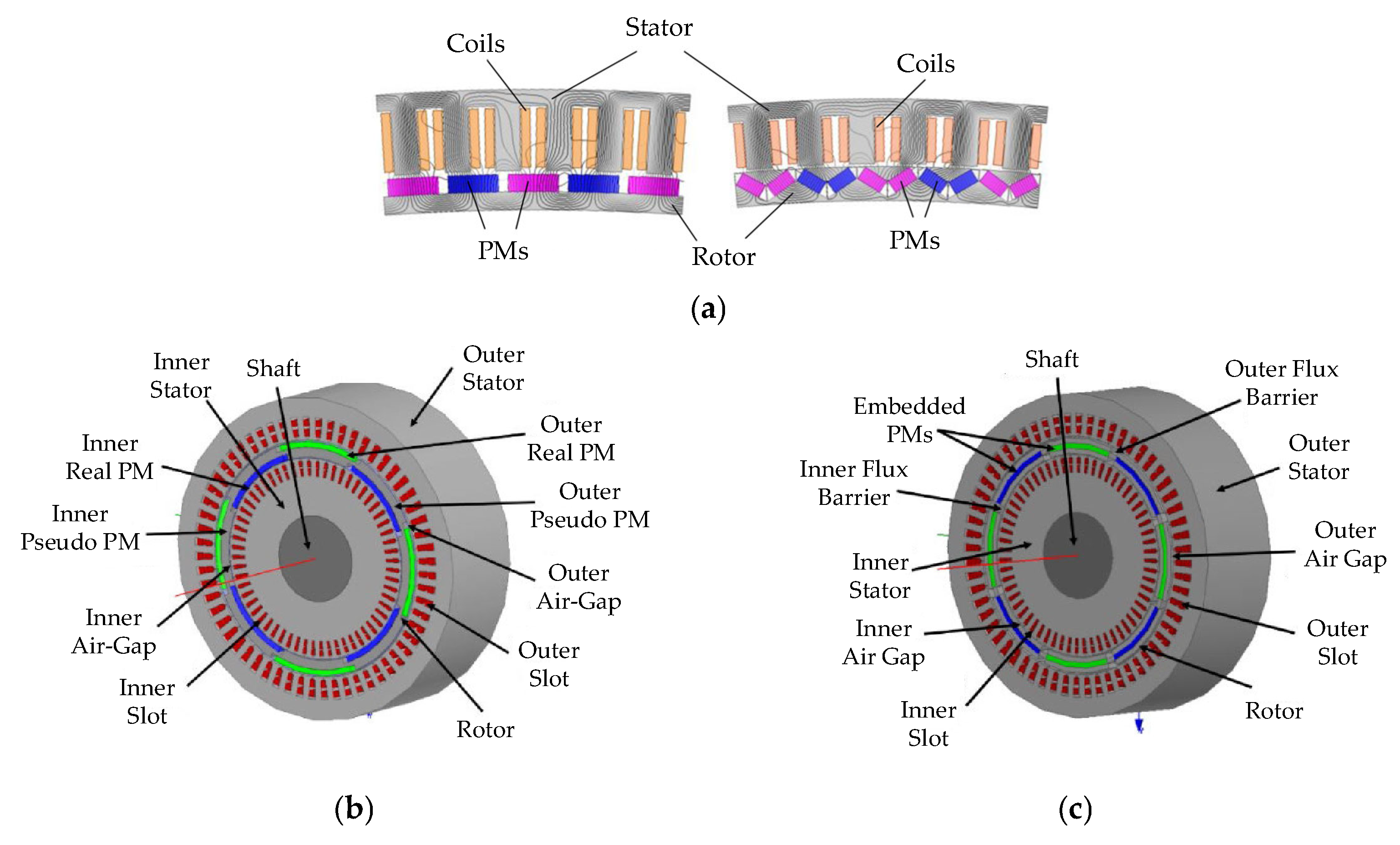
In [73], a comparison is presented between two fundamental PM generator designs intended for DD 7 MW wind turbines, both based on concentrated windings: surface-mounted PM machines (SPM) and interior PM machines (IPM) with a V-shaped rotor configuration. Both machines utilize fractional-slot concentrated windings, which allow for shorter end windings, increased power density, and improved manufacturing efficiency.
The SPM generator is characterized by a high pole count (220) and a simplified structure, whereas the IPM generator leverages flux concentration in the rotor and involves a greater number of design variables, including the dimensions of magnetic ribs and bridges.
In the context of wind power applications, the SPM machine offers lower total mass (37.1 t), reduced magnet mass (4.9 t), and lower overall cost (540 kUSD), as well as lower cogging torque and better demagnetization resistance, making it an attractive solution for systems requiring reliability and simplicity. On the other hand, the IPM design provides higher electromagnetic torque density and lower magnet losses due to pole shielding, though at the expense of increased total weight (40.5 t), higher magnet mass (5.1 t), and increased cost (554 kUSD).
The analysis results indicate that both configurations are suitable for large-scale wind turbines. However, the selection of a specific design should be based on a trade-off between compactness, efficiency, and manufacturing and operational costs.
In [74], the design and analysis of a large radial-flux PMSG intended for DD operation in 5 MW wind turbines is presented. Two configurations were developed: one with an internal rotor and the other with an external rotor, while maintaining the same fundamental electromagnetic parameters—such as pole number, number of slots and phases, type of NdFeB magnets, and magnetic steel grade. The design process was based on magnetic circuit analysis and finite element simulations using SPEED and Flux software.
The results showed that the internal rotor configuration achieved a higher air gap flux density (0.88 T vs. 0.85 T) and greater output power under identical boundary conditions. In contrast, the external rotor design offers simplified mechanical integration with the turbine rotor, improved magnet cooling conditions, and lower manufacturing costs due to reduced consumption of active materials.
Both configurations feature a compact design, use of double-layer concentrated windings, and optimized air gap dimensions, making them attractive solutions for modern low-speed wind turbines.
In [75], a novel type of five-phase PMSG was designed and analyzed for wind energy applications. The construction features a dual-stator configuration with two sets of five-phase windings, providing enhanced power density and fault-tolerant operation capability. A key innovation is the implementation of so-called pseudo-poles—a design that enables the creation of eight magnetic poles using only four actual magnets on each side of the rotor.
Electromagnetic analyses, performed using a Dynamic Magnetic Circuit Model and the Finite Element Method (FEM), confirm improved efficiency and power density compared to reference designs.
The authors of [76] present a modern design of a synchronous generator—a Double-Stator Cup-Rotor PMSG—optimized for high-efficiency wind power applications. The paper describes the structure, operating principle, and derives the corresponding equations governing the machine’s behavior. The optimization of design parameters was carried out using the Analytic Hierarchy Process and validated through simulations in Maxwell software using FEM.
Magnetic field calculations under both no-load and loaded conditions confirmed the correctness of the design. Compared to conventional PM generators, the proposed generator exhibits lower electrical losses, a simplified mechanical structure, reduced mass, and compact dimensions, while simultaneously increasing electrical energy output. These characteristics make it particularly well-suited for application in large-scale wind turbines.
In [77], a detailed parametric analysis is presented for a low-speed radial-flux PMSG designed for DD applications in small wind turbines. The baseline configuration includes 15 slots and 10 poles, concentrated windings, and a rotor with NdFeB magnets. Based on this configuration, a series of design modifications were investigated, including core material substitution (from silicon steel to general-purpose steel), variations in air gap length, segmentation and oversizing of magnets, the use of a coreless rotor, and the skewing of stator teeth.
The study found that replacing curved magnets with segmented rectangular magnets reduced material costs by 30% without a noticeable decrease in air gap flux density. The use of overhang PMs increased output power by up to 23%. The authors also proposed the concept of using an air-core (coreless) rotor. This modification ensured that the available radial steel of the rotor was sufficient only to maintain the required flux density without saturation and to provide mechanical fastening. Implementing a coreless rotor significantly reduced the total mass of the device (by 70% rotor weight), while increasing the power-to-weight ratio by 30%. Reduction of cogging torque was achieved through appropriate stator tooth skew angles, lowering the electromotive force harmonic content from 20% to 3.4%.
Overall, the study demonstrates that proper geometric and material optimization can significantly reduce production costs and enhance the operational performance of PMSGs in small-scale wind energy systems.
Selected PMSG designs discussed above are shown in Figure 3.

5.2. Superconducting Synchronous Generators

In [78], the authors described four fundamental design concepts for HTS synchronous generators, analyzing their potential application in DD wind turbine systems. It was indicated that, compared to conventional machines, HTS generators offer significantly greater design flexibility, enabling the adaptation of machine topology to specific application requirements—particularly in terms of mass, efficiency, and cost. Each of the four proposed concepts was evaluated with respect to its electromagnetic, mechanical, and thermal properties.
The first concept involves the use of a conventional stator with iron teeth and an HTS rotor with magnetic pole bodies, which can operate at either room or cryogenic temperatures. The main advantage of this configuration is the reduction of rotor losses, resulting in higher efficiency. However, this design does not offer significant benefits in terms of mass or volume reduction, which limits its attractiveness in applications where weight is a critical factor.
The second concept also employs a conventional stator, but incorporates an HTS rotor with non-magnetic pole bodies. The key difference from the first configuration is the elimination of expensive magnetic materials operating at low temperatures, which simplifies thermal insulation. However, achieving the required air gap flux density in this setup demands a larger amount of superconducting wire, potentially increasing the total cost.
The third concept is based on a stator with windings placed in the air gap and an HTS rotor with magnetic pole bodies. This configuration enables significantly higher air gap flux densities than those achievable with classical designs. Additionally, the rotor iron can operate in a state of deep magnetic saturation, due to the predominantly DC nature of the magnetic field, leading to substantial reductions in machine mass and volume while maintaining high efficiency.
The fourth and final concept also features a stator with air-gap windings, but combines it with an HTS rotor with non-magnetic pole bodies. Although this approach requires more HTS conductors than the third configuration, it eliminates the need for costly iron components operating under cryogenic conditions. As a result, it offers further mass reduction while maintaining competitive costs. Based on projected bulk prices for second-generation (2G) HTS conductors, the fourth concept was identified as the optimal configuration for the proposed HTS generator design.
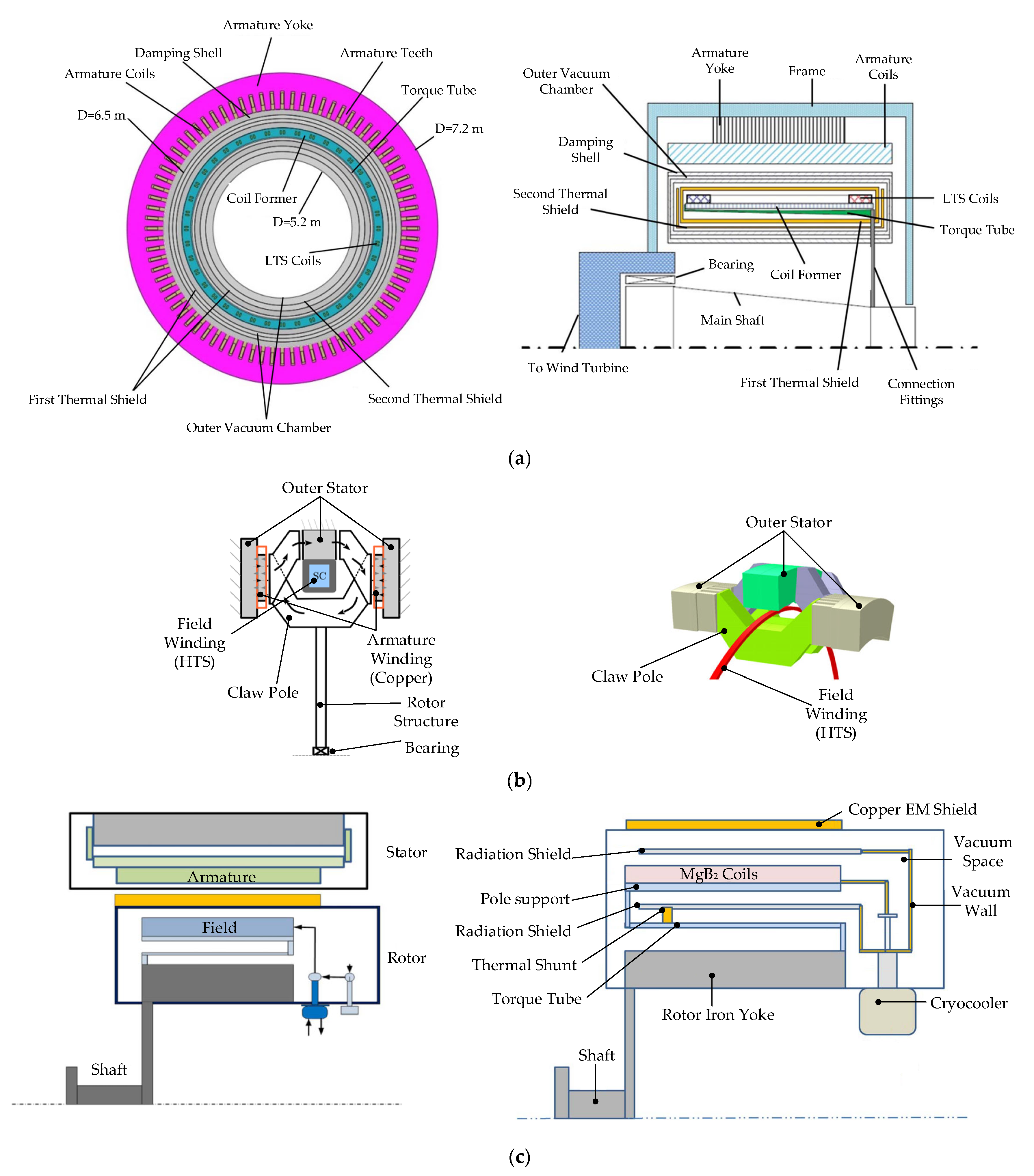
The claw-pole generator presented in [79] is a superconducting machine designed for 10 MW offshore wind turbines. The machine operates at a rotational speed of 10 rpm and utilizes 88 magnetic poles. Its total outer diameter is 6.63 m, with an axial length of 1.38 m, and a total mass of 184 tons, of which 68% is structural mass. A dual armature winding system (two independent windings on opposite sides) is employed, allowing continued operation of the generator even in the event of a partial failure of one winding section.
The machine achieves a maximum magnetic flux density of 2.3 T through the use of VacoFlux50, a cobalt–iron alloy with high magnetic saturation. The magnetic field is generated by four segmented cryostats housing stationary superconducting windings. Depending on the conductor type, the superconducting tape requirement is 15 km for MgB2 at 30 K, or 13.5 km for YBCO at 65 K. The total magnetomotive force (MMF) of the winding system is 32.4 kA·turns, and the induced phase voltage reaches 3.3 kV.
In terms of performance, the generator achieves an efficiency of 94.5%. Copper winding losses amount to 510 kW, while the cooling power requirement is 24 kW (using four Cryomech AL230 cryocoolers). The total torque generated by the machine is 9549 kNm, resulting in a mass-to-torque ratio of approximately 19.3 kg/kNm. This is favorable compared to typical DD PM generators, which usually exceed 30 kg/kNm. Although the claw-pole generator is slightly heavier than some other HTS machines, it compensates with a simplified design, high reliability, and low superconducting material usage, making it a competitive option for offshore applications.
The authors of [80] present the design of a 10 MW-class superconducting synchronous generator intended for wind turbine applications. Two models are analyzed: Model-1 (8-pole) and Model-2 (12-pole). Both variants are three-phase, operate at an interphase voltage of 3.3 kV, and have a rotational speed of 10 rpm. The main difference between the models lies in the number of poles, which influences the magnetic field distribution and the required amount of HTS material. The generators were designed and evaluated using FEM.
Both configurations use HTS excitation windings (YBCO tape), cooled to 20 K. The stator windings utilize a conventional two-layer distributed winding structure. The number of slots per phase per pole is six for Model-1 and four for Model-2, which affects the total winding layout. A small air gap is assumed in the design, with the HTS winding located on the rotor side and the copper stator winding on the stator side. To mitigate the impact of stray fields, a magnetic back yoke is employed as a shielding element.
FEM analysis demonstrated that both models can achieve a magnetic flux density of 2.5–3 T in the region of the stator winding. Under resistive load conditions, Model-1 delivers 10.1 MW, while Model-2 reaches 9.83 MW. The measured synchronous reactance is 0.203 Ω for Model-1 and 0.217 Ω for Model-2. The authors highlight that such low reactance values are typical for HTS designs and may lead to very high short-circuit currents, necessitating the implementation of specialized protection systems in practical applications.
As part of the EcoSwing project, carried out under the EU Horizon 2020 program, a full-scale HTS synchronous generator was developed and tested for operation in a 3.6 MW wind turbine, achieving a TRL of 6–7. The generator’s rotor was equipped with 40 superconducting coils, each 1.4 m in length, manufactured from over 20 km of second-generation HTS tape produced during the course of the project. Over 90% of the coils met performance specifications during pre-assembly testing, confirming the industrial readiness of the HTS technology.
The cryogenic system, implemented using Gifford–McMahon cold heads and a rotational coupling connected to stationary compressors, demonstrated stable operation below the target temperature of 30 K. Following stationary testing at the IWES facility in Bremerhaven, the generator was installed in an existing wind turbine in Thyborøn, Denmark, where it successfully generated electricity for over 650 h of grid-connected operation [81]. The EcoSwing project was officially completed in 2019, marking an important step toward the commercialization of superconducting generators for wind energy applications.
The design presented in [82] is based on a 10 kW synchronous generator with eight poles, utilizing superconducting rotor coils made from HTS tapes arranged in a race-track configuration. The stator is coreless, air-cooled, and equipped with copper windings embedded in an iron magnetic shield. The entire machine is designed for DD operation, simplifying the mechanical system and reducing potential failure points.
The design accounts for geometric constraints, such as the minimum bending radius of HTS tapes, while ensuring the required electromagnetic and mechanical performance within a compact structure suitable for integration into a wind turbine nacelle.
An advantage of this configuration is the ability to achieve high magnetic flux density in the air gap, comparable to that of state-of-the-art PMs, while simultaneously reducing the mass and volume of the generator. By eliminating the gearbox and potentially decreasing the overall weight of the drivetrain, such a machine is well-suited for use in large offshore wind turbines, where transportation, installation, and maintenance costs are critical considerations.
A recent patent [83] describes the structure and operating principle of an HTS synchronous generator designed for DD wind turbine applications. The design utilizes HTS windings mounted on the rotor of the generator, while the stator contains conventional three-phase copper windings, in which the output voltage is induced.
The generator has a cylindrical structure with a horizontal axis, which is typical for wind turbines. The rotor includes magnetic poles in the form of HTS windings mounted on the rotating shaft. The HTS assembly is housed within a cryostat that maintains the operating temperature required to preserve superconductivity, typically in the range of 20–77 K. A cooling system—usually based on liquid nitrogen or cryogenic refrigerators—is also provided.
The machine operates by generating a magnetic field through the rotating superconducting rotor windings. The rotational motion is directly transferred from the wind turbine blades to the generator shaft without the use of a gearbox, which increases system reliability and reduces mechanical losses.
The authors of [84] present the concept of a gearless 10 MW superconducting synchronous generator, in which both the rotor and stator utilize windings made from MgB2 (39 K) superconductors. The generator features a synchronous design with a 24-pole DC-excited rotor and a three-phase stator. The rotor windings are implemented as race-track coils made from MgB2 cables, cooled to 15–20 K using two-stage cryocoolers. The stator also uses MgB2 coils, housed in a separate cryostat and cooled independently. Both cooling systems operate in a closed-loop gaseous helium cycle, with pumps and cryocoolers located outside the rotating part of the machine.
The entire generator has a diameter of less than 5 m, a length under 2 m, and a total mass of approximately 52 tons. The rotor includes an additional electromagnetic shield made of copper at ambient temperature, which suppresses higher-order harmonics and protects the superconducting windings from high AC losses.
The generator operates as a conventional synchronous machine: DC excitation current in the rotor windings generates a magnetic field, which, upon rotation, induces AC voltage in the stator windings. The use of MgB2 superconductors enables the generation of strong magnetic fields with minimal energy losses, thereby increasing efficiency and reducing the overall mass of the machine.
Despite the greater complexity of cooling AC windings in the stator, superconductivity on the stator side is feasible due to the low operating frequency (10 rpm) and the use of optimized cable structures. The machine achieves an overall efficiency exceeding 98%, and its compact design allows for factory assembly and single-piece transport, meeting industrial requirements for offshore wind turbine installation.
The superconducting generator with MgB2 windings has a total mass of approximately 52.5 tons. The heaviest components include the rotor iron yoke (10.2 tons), stator case (8.3 tons), stator iron yoke (7.6 tons), and cooling systems (7.5 tons). The rotor field winding, including its support structure, weighs nearly 3.0 tons, while the stator winding weighs only 140 kg.
The total cost of the generator (excluding power electronics) is estimated at 2200 kUSD, comprising 750 kUSD for the MgB2 windings, 735 kUSD for the cryogenic system (including 29 cryocoolers), and 450 kUSD for mechanical components. Including the cost of power converters (1000 kUSD), the total system cost amounts to 3200 kUSD.
The 10 MW superconducting generator, developed by Marino et al. [57] as part of the EU co-funded SUPRAPOWER project completed in 2017, is a synchronous direct-drive machine in which the magnetic field is produced by MgB2 superconducting coils cooled to 20 K. These coils are placed in modular cryostats mounted on a warm-iron rotor, simplifying the design. Cooling is provided by rotating Gifford–McMahon cryocoolers without the use of liquid cryogens. The stator uses copper windings in a toothless air-gap configuration, allowing for higher current density and reduced losses.
The machine operates at 8.1 rpm, 2280 V, and 2665 A, generating a 1.5 T air-gap field. With 48 poles, it delivers 11.8 MNm torque and 95.2% efficiency. Compared to a PMSG, the active part weight is reduced by 26% and total weight by 16%. The higher magnetic flux and elimination of rare-earth magnets result in a lighter, more cost-effective design suited for offshore wind applications.
In terms of mass and cost, the superconducting generator performs favorably compared to a permanent magnet generator. The active parts weigh 161.6 tons, representing a 26% reduction compared to the 219.3 tons of the PM design. Including structural components, the total weight is 444.1 tons—16% less than the alternative solution, which weighs 530.9 tons. This weight reduction also enables a lighter turbine tower, with a potential mass reduction of around 11%. The cost of active components in the superconducting generator is estimated at EUR 307,000 per MW (assuming an MgB2 wire cost of 3 EUR/m), which is comparable to the permanent magnet generator’s EUR 313,000 per MW.
The superconducting generator described in [85,86] is a fully superconducting synchronous machine with a rated power of 10 MW, developed as part of the SupraGenSys project. Both the stator and rotor windings are made of HTS tapes, which allows for the elimination of resistive losses under superconducting conditions. A two-layer concentrated tooth winding was used in the stator, offering simpler manufacturing and reduced HTS conductor length. The generator’s parameters were analyzed using an analytical model in the d/q coordinate system and verified through finite element simulations (FEM), which account for the multilayer structure of the HTS tape, the E-J power law, and the dependence of the critical current on the magnitude and angle of magnetic flux density.
The machine operates by synchronously generating power through the interaction of magnetic fields produced by superconducting windings in the rotor and stator. During a short circuit, when the current exceeds the critical value, a quench occurs—a local transition of the HTS material to a resistive state—leading to increased resistance and heat generation. Simulations showed that the generator’s behavior under fault conditions largely depends on the thermal and critical current properties of the rotor winding. The SupraGenSys project was completed in 2022 and focused on the conceptual design of the machine. It is currently continued as SupraGenSys2 (2023–2026), within which the construction and testing of a prototype generator is planned.
The 15 MW-class (HTS) Flux Switching Synchronous Generator (FSSG) [87] represents an innovative approach to large-scale power generation by integrating HTS field coils directly into the stator. This architectural shift eliminates the need for rotating superconducting components, simplifying the design and implementation of both the cooling and excitation systems. The rotor, composed of silicon steel, features a salient-pole structure but carries no windings, thereby reducing mechanical complexity and potential failure points. The stator houses both the armature windings and the HTS field coils, the latter built from SuperPower’s SCS12050-AP tape and arranged as multiple single pancake coils with carefully controlled spacing to optimize thermal management and magnetic performance.
The generator operates on the flux switching principle, wherein the motion of the rotor causes alternating magnetic flux linkage in the stator teeth. This dynamic variation induces an AC electromotive force in the armature windings without requiring the HTS coils to rotate. The machine is rated at 15 MW output power, 3.3 kV terminal voltage, and operates at 900 rpm and 60 Hz. Key performance evaluations, including FEM-based stress analysis and transient electromagnetic simulations, confirm that the rotor withstands operational stresses and the generator meets its rated performance with low harmonic distortion and acceptable iron losses. Among the notable advantages are increased system reliability, enhanced efficiency due to superconductivity, and reduced system complexity, making the proposed FSSG a promising candidate for high-power applications such as offshore wind or distributed energy systems.
Figure 4 illustrates representative designs of generators employing superconducting windings.

5.3. Axial-Flux Generators

The design described in [88] features a slotless synchronous PM generator with axial magnetic flux and toroidal geometry. Unlike conventional slotted machine topologies, the phase windings are placed directly in the air gap, which eliminates local magnetic field nonlinearities and reduces losses associated with flux leakage. A double-disc rotor with PMs mounted on both sides of the wound stator allows for a favorable power-to-volume ratio and facilitates a modular construction approach.
The design process was supported by FEM analysis, enabling precise optimization of core geometry and magnet volume to achieve the target air gap flux density.
In the context of low-speed wind turbine applications, the absence of slots significantly reduces electromagnetic torque ripple, improving the generator’s performance under dynamically changing rotational speeds. Additionally, the uniform distribution of windings supports efficient heat dissipation, which—together with class H insulation—ensures safe operation under localized temperature increases.
The generated electrical energy is converted using a conventional AC–DC–AC power electronics system, consisting of a three-phase diode bridge and a PWM-modulated inverter, enabling grid synchronization and effective operation at low wind speeds, where traditional mechanical systems are inefficient.
The authors of [89] present an innovative generator design for wind energy applications—an axial field flux-switching generator. This generator features a double-stator structure with a single rotor positioned between two stators, each containing both windings and PM segments with opposite polarities. The salient-pole rotor contains no active components, which reduces the risk of demagnetization at elevated temperatures and simplifies the mechanical structure.
The windings are concentrated, spanning pairs of stator teeth, and the operating principle is based on the periodic switching of magnetic flux depending on the rotor position.
To evaluate the electromagnetic performance, a three-dimensional FEM analysis was performed. The study examined the magnetic field distribution under both no-load and armature reaction conditions, confirming that most of the armature flux is confined within the stator teeth, which reduces the risk of irreversible demagnetization of the magnets. Significant local saturation was observed during maximum overlap between the rotor poles and stator teeth, and the dominant role of the PMs in shaping the air gap flux was confirmed. The analysis showed a sinusoidal waveform of the electromotive force and flux linkage in the phase windings, enabling classical synchronous control.
Despite the relatively high cogging torque resulting from flux concentration, its reduction can be achieved by applying an appropriate skew angle to the rotor. Experimental tests conducted on a prototype machine confirmed good agreement with simulation results, validating the adopted design methodology.
In [90], cogging torque is analyzed and optimized in a yokeless and segmented armature (YASA) axial-flux machine with a soft magnetic composite (SMC) core. The machine is built in a TORUS topology featuring a double-rotor, single-stator configuration, with fan-shaped surface-mounted PMs on the rotor discs. The use of SMC material enables better exploitation of its magnetic and thermal isotropy, while also simplifying the geometric shaping of the stator core—evident in the trapezoidal “shoes” that extend radially and circumferentially beyond each stator tooth.
To minimize cogging torque, the study examined the influence of four design parameters: the magnet pole arc ratio (αₚₘ), the magnet skew angle (β), the stator shoe width ratio (αₛ), and the stator shoe angular offset (δ). It was shown that the cogging torque profile in a YASA machine with an SMC core significantly differs from that of traditional Axial-Flux Permanent Magnet (AFPM) machines and steel-core YASA machines, mainly due to the unique geometry of the air gaps, teeth, and magnetic circuit.
Optimization was carried out using a response surface methodology combined with a genetic algorithm, while maintaining constant voltage and output power parameters. The final design achieved a 91% reduction in peak cogging torque (from 2.14 Nm to 0.18 Nm), with virtually no change in back-EMF or rated torque values. Validation was performed using three-dimensional finite element analysis (3D FEM), confirming the accuracy of the optimization model.
The authors of [91] analyze the cogging torque in an Axial-Flux Flux-Switching PM Machine, in which both the stator and rotor have a toothed structure with clearly defined magnetic poles. This geometry promotes high magnetic flux density in the air gap, which enables the generation of a large electromagnetic torque, but also results in significant cogging torque compared to conventional PM machines.
To mitigate this effect, the authors proposed introducing a magnetic bridge between adjacent stator teeth. This feature stabilizes the magnetic permeability between the stator and rotor during rotation, reducing the variation of co-energy and thereby decreasing cogging torque.
The effectiveness of the method was evaluated using three-dimensional FEM analysis for two stator geometries: Parallel Poles and Parallel Slots, and Parallel Teeth and Parallel Slots.
In both configurations, the use of a magnetic bridge significantly reduced cogging torque—by up to 84%—with an acceptable reduction in average electromagnetic torque (up to 28%, depending on magnetic bridge thickness). Further optimization was achieved by adjusting the stator tooth width and rotor pole angle. With appropriately selected parameters (magnetic bridge thickness: 2 mm, tooth width: 8.5°, pole width: 14.5°), a 76% reduction in cogging torque was obtained with only a 15% drop in usable torque.
The effectiveness of the method was confirmed experimentally, demonstrating its superiority over traditional techniques such as rotor skewing or tooth notching.
The authors of [92] present a novel yokeless axial-flux machine topology that combines flux-switching operation with PMs embedded in the stator. The design features a single stator and two rotors positioned with an electrical phase shift of 180 degrees. This configuration eliminates the stator yoke, increases the available winding space, and significantly reduces cogging torque. The windings are concentrated and arranged to ensure a unity winding factor, while each stator pole incorporates laminated “sandwich-type” core segments placed between pairs of PMs with opposing magnetization directions.
The proposed design combines the benefits of flux-switching machines and axial-flux machines. The use of phase-shifted rotors results in a drastic reduction in cogging torque—to only 3.5% of the rated torque—while simultaneously achieving an increase in average electromagnetic torque of approximately 45% compared to a classical PM machine, and 22% compared to a flux-switching machine with segmented windings.
The topology was optimized using response surface methodology and three-dimensional FEM analysis, which enabled precise tuning of key geometric parameters such as rotor pole and stator tooth angles, magnetic segment widths, and the inner-to-outer diameter ratio. The final performance characteristics were experimentally validated using a built prototype.
Additionally, the article describes the development and implementation of a sensorless control strategy, incorporating a sliding-mode observer and space vector modulation, which provided good dynamic response and reduced torque and flux ripple during operation.
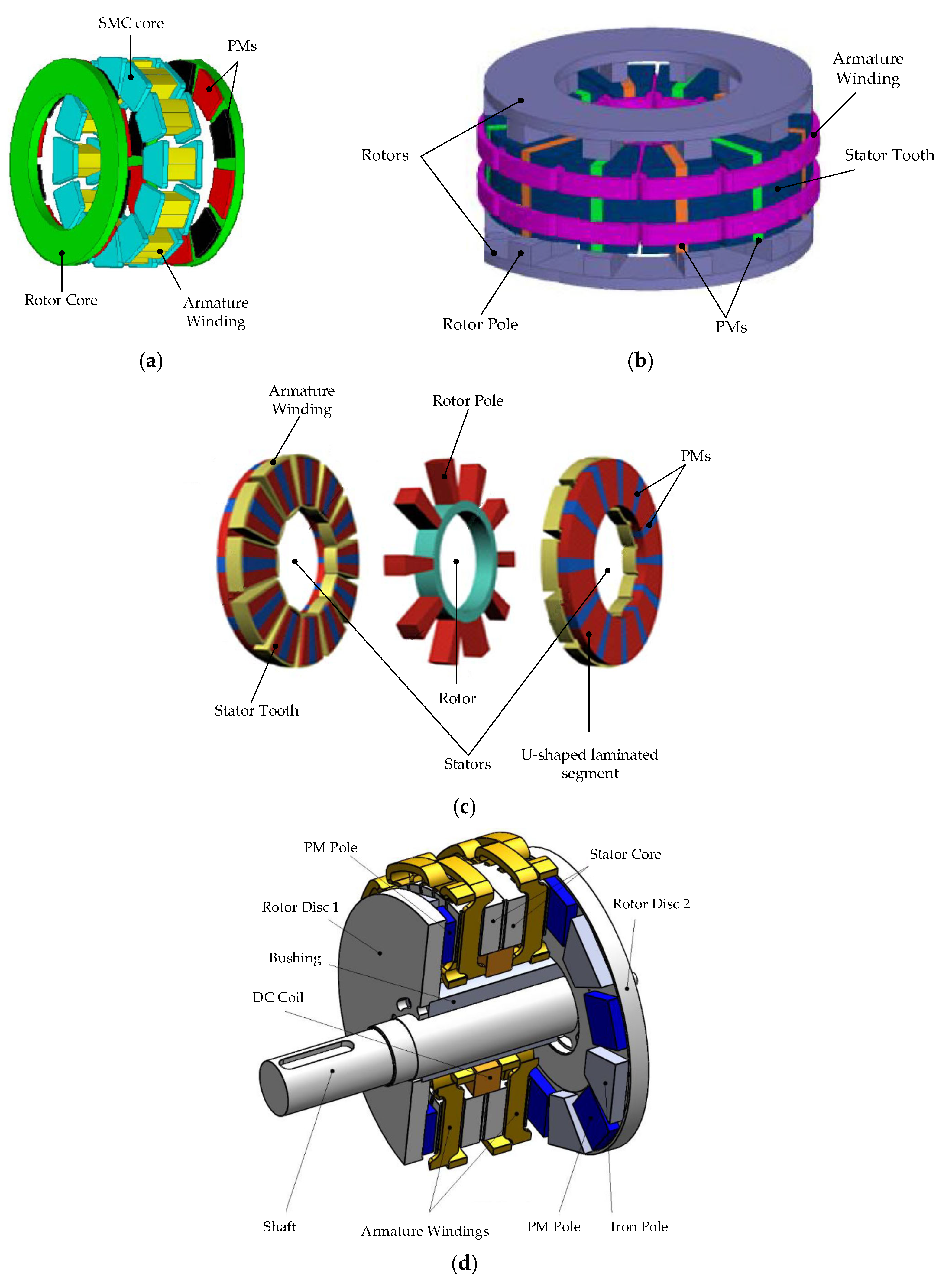
Figure 5 presents various AFPM machine topologies, highlighting differences in rotor–stator configurations, magnetic circuit design, and excitation methods. The illustrated designs include machines with SMC cores, segmented U-core stators, dual-rotor switched topologies, and field-controlled stator structures.
The authors of [93] introduce a novel axial-flux machine design featuring a hybrid excitation system. The machine employs a double-disc rotor with PMs and iron poles of differing geometries and magnetic properties, while the stator incorporates an additional DC-excited field coil. This configuration enables active control of the magnitude and direction of the air-gap flux density, allowing for both flux enhancement and flux weakening depending on the current operating conditions.
FEM analysis revealed that the flux control range reaches approximately 50%, without the risk of demagnetizing the PMs. The applied machine topology enables a high starting torque and supports increased maximum rotational speed in flux-weakening mode, making it particularly suitable for wind turbines operating over a wide speed range.
The use of a brushless excitation system enhances system reliability, and the machine achieves high efficiency (up to 95%) with effective air cooling, as confirmed by experimental testing. Additional advantages include reduced PM usage and the ability to adapt machine performance to variable environmental conditions through flexible excitation control.

5.4. Comparison

In [94], a comprehensive comparison was conducted between three types of synchronous generators intended for 10 MW wind turbines operating at low rotational speeds (8 and 10 rpm). The analysis covered machines with HTS excitation, conventional copper excitation, and PM excitation. All designs were developed using a consistent calculation methodology and optimized with respect to real-world material constraints and cooling requirements.
The HTS generator exhibited the lowest total mass and highest efficiency, even when accounting for the power consumed by the cryogenic cooling system. Its short winding length, high air-gap flux density, and limited number of required cryostats made the HTS configuration exceptionally compact and energy-efficient. Notably, the mass of the HTS windings was more than seven times lower than the mass of the permanent magnets needed in the PM generator.
The conventional copper-excited generator served as the reference case. It had the highest total mass and lowest efficiency among the three types. Its main advantages were simplicity and relatively low manufacturing cost, but the high mass made it suboptimal for offshore applications, where logistics and installation constraints are critical.
The permanent magnet generator showed higher efficiency than the copper design but was outperformed by the HTS version. It required a large quantity of magnetic materials, significantly increasing the overall cost—particularly when using high-volume neodymium magnets. The limited flux density in the air gap, inherent to the material properties, negatively affected the compactness of the design.
In summary, among the three generator types analyzed, the HTS-excited machine offered the best performance in terms of efficiency, mass, and energy losses. Despite its higher technical complexity and cryogenic cooling requirements, HTS technology shows the greatest potential for application in modern high-power wind turbines, especially in DD systems.
Axial-flux permanent magnet machines (AFPM) and radial-flux permanent magnet machines (RFPM) represent two distinct topological classes of motors and generators with permanent magnets. They differ in terms of magnetic field distribution, geometrical layout, and thermal and mechanical characteristics. The authors of [95] present a direct comparison of both machine types with identical volume and electromagnetic configuration, focusing on their thermal performance and torque capabilities across various aspect ratios.
The study results indicate that AFPM machines, particularly those with coreless rotors and Nd-bonded magnets, demonstrate superior thermal performance in applications requiring a compact, flat design. Due to the larger contact area between the stator and housing, as well as lower eddy current losses, AFPMs are capable of continuous operation without active cooling systems, significantly reducing manufacturing and operational costs.
In contrast, RFPM machines, although built with traditional structures using Nd-sintered magnets and laminated steel cores, generate higher copper and iron losses under high torque and speed conditions. This leads to excessive temperature rise, particularly in flattened designs. For low aspect ratios (e.g., 0.38), winding temperatures in RFPMs can exceed 120 °C, necessitating additional cooling solutions.
Moreover, AFPM machines exhibit higher torque density, lower total harmonic distortion (THD) of back-EMF, and a better power factor compared to RFPMs. However, at higher aspect ratios (above 0.7), radial-flux designs may regain an advantage in terms of losses and efficiency.
Based on the reviewed literature, the following Table 5 summarizes a comparison of the main types of synchronous generators used in high-power (10 MW) DD wind turbines. The comparison includes key technical, operational, and technological characteristics of the three most commonly considered generator types: HTS generators, PM generators, and electromagnetically excited (copper) generators.
This comparison highlights that HTS generators offer superior performance in terms of efficiency, compactness, and offshore applicability, despite their higher system complexity and cost. PM generators represent a mature, efficient compromise but rely heavily on rare-earth materials. Copper-excited generators, while simpler and cheaper, are generally less suited to offshore environments due to their bulk and lower efficiency. Table 6 presents the parameters of selected innovative generators described in scientific publications.
The analysis of selected innovative generators described in the literature highlights clear trends in the design of energy conversion systems for modern wind turbines. Superconducting generators offer very high efficiency (up to 98%) and significantly lower active part mass compared to conventional DD solutions. However, this comes with high costs—mainly due to the price of superconducting materials and the complexity of the cryogenic cooling system. Nevertheless, their potential to reduce nacelle mass and enhance system reliability (by eliminating the gearbox) makes them an attractive technology for future large offshore wind turbines.
In contrast, PMSG generators with gearboxes are characterized by a very favorable mass and volume-to-power ratio while maintaining high efficiency (>98%) and relatively low costs. They currently represent the most economically viable solution for large turbines, despite the presence of the gearbox, which can affect overall system reliability. DD PMSG solutions, while mechanically simpler, remain bulky and expensive, which limits their application in large-scale installations.
For lower-power generators (<1 MW), it is possible to achieve very high efficiency and a significant degree of miniaturization, making them an excellent choice for distributed or specialized applications. Overall, the choice of optimal generator technology should be based on a compromise between efficiency, mass, cost, reliability requirements, and ease of maintenance—a balance clearly reflected in the examples compared in the literature.

6. Summary and Conclusions

This study analyzed the current state and development potential of various types of synchronous generators used in 10 MW DD wind turbines. Special attention was given to HTS generators, which offer significant advantages in terms of mass reduction, efficiency, and integration with modern offshore energy systems. The key observations and conclusions are summarized below.

6.1. Commercialisation Opportunities for New Generator Concepts

New generator concepts, including superconducting machines, pave the way for further miniaturization and efficiency improvements in wind energy conversion systems. The EcoSwing project demonstrated that it is feasible to design and operate an HTS generator in a real 3.6 MW wind turbine, achieving TRL 6–7. Over the next 5–10 years, the commercialization of such technologies may accelerate—particularly in the offshore sector, where high installation costs justify investment in lighter and more efficient solutions. However, it is necessary to overcome the most important challenges, such as mechanical stresses in HTS windings, reliable cryogenic cooling of excitation windings at low maintenance costs, and modular design.
On the other hand, well-established and commercially available PM generators currently dominate the market and remain the preferred option for 8–15 MW turbines, due to their proven performance, reliability, and mature supply chains.

6.2. The Future of Superconductors in Wind Turbines

The prospects for implementing HTS technology in wind energy depend on the continued reduction in the cost of superconducting tapes and advancements in cryogenic technology. A key role may be played by the development of alternative materials, such as MgB2 (39 K), which are significantly cheaper and easier to manufacture than YBCO, albeit requiring operation at lower temperatures (~20–30 K).
The use of lower-cost cryocoolers and improved insulation system efficiency could substantially reduce the total cost of HTS generators. Ongoing research into minimizing AC losses and enhancing the reliability of cooling systems will be crucial for enabling wider adoption of HTS technology in the wind energy sector.

6.3. HTS-SG Technology with the Greatest Potential

Among the analyzed HTS generator designs, topologies with an HTS rotor and a conventional stator show the greatest commercial potential. Particularly promising are configurations with non-magnetic rotor pole bodies, which simplify thermal insulation and allow for high efficiency with moderate mechanical complexity.
“Race-track” HTS designs, featuring compact coil arrangements and integrated rotor cryogenics, have demonstrated high performance in both laboratory and field tests. Their continued development could form a solid foundation for the implementation of HTS synchronous generators in wind turbines exceeding 10 MW capacity.

6.4. The Biggest Barriers to Implementing HTS in Wind Energy

The main implementation barriers for superconducting generators in wind energy are the following:
  • High cost of HTS materials, particularly YBCO and GdBCO, which significantly impact the overall capital expenditure;
  • Complexity and reliability of cryogenic systems, which must operate under harsh offshore conditions with limited access for maintenance;
  • Technical challenges related to the cooling of the rotor, which, as a rotating component, complicates the design of efficient and reliable cryogenic systems;
  • Risk of quench (sudden loss of superconductivity), which can lead to mechanical damage and lengthy repair procedures;
  • Lack of operational experience in real-world conditions for high-power machines (>5 MW), affecting the confidence of investors and manufacturers;
  • Need for standardization and technical regulations for HTS components in energy applications to ensure interoperability, safety, and certification readiness.
Despite these challenges, advances in materials science, cryogenics, and power electronics suggest that HTS technology has the potential to play a significant role in the future of large offshore wind turbines. Continued innovation in these areas may help overcome current barriers, paving the way for lighter, more efficient, and high-performance generators in next-generation renewable energy systems.

6.5. Further Research Directions

The comparative analysis of various generator types used or considered for wind turbines highlights their differing commercialization potential and distinct technological challenges. HTS generators, despite their high long-term potential, still face significant cost and technical barriers (expensive HTS tapes, quench risk, complexity of cryogenic systems). However, advancements in cheaper materials (such as MgB2), more efficient cryogenics, and system standardization could substantially improve their competitiveness. In contrast, PM generators, currently the industry standard, face challenges related to the cost and supply of rare-earth elements and thermal management—driving interest in rare-earth-free magnets and circular economy approaches to magnet recycling.
Electromagnetically excited generators and DFIG still hold an important market position, particularly in medium-power systems or where cost-effectiveness is critical. Their future development will depend on further optimization of mass and efficiency, as well as improved integration with modern control and power conversion systems (such as HVDC). Meanwhile, SCIG have limited applicability in large turbines due to the lack of field control and lower efficiency at variable speeds, though they may find niche applications in simple, low-cost configurations combined with full AC–DC–AC conversion systems. Overall, the future evolution of generator technologies will require a balanced trade-off between energy efficiency, material costs, system reliability, and compatibility with next-generation power systems.
Table 7, below, presents a synthetic comparison of the discussed generator types in the context of their suitability for wind turbines > 10 MW, taking into account their commercialization potential, current TRL, implementation challenges, and future development pathways.

Author Contributions

P.P.: Conceptualization, Writing—original draft, Project administration, Resources, Writing—review and editing. C.K.: Formal analysis, Resources, Writing—review and editing. All authors have read and agreed to the published version of the manuscript.

Funding

This research was funded by National Science Centre, Poland grant number 2024/08/X/ST8/00560.

Conflicts of Interest

The authors declare no conflict of interest.

References

  1. Chang, F.; Khoo, R.; Ongel, A.; Lienkamp, M. Rapid Energy Consumption Assessment of Vehicle Concepts for Public Transport Systems without Detailed Deployment Data. In Proceedings of the 2018 IEEE Innovative Smart Grid Technologies—Asia (ISGT Asia), Singapore, 21–24 May 2018; pp. 452–455. [Google Scholar]
  2. Valeriy, K.; Viktor, S.; Petro, H.; Myamlin, S.; Yevhen, K.; Vitalij, L. Hybrid Railway Traction Power Supply System. In Proceedings of the 2020 IEEE 4th International Conference on Intelligent Energy and Power Systems (IEPS), Istanbul, Turkey, 7–11 September 2020; pp. 208–211. [Google Scholar]
  3. Gyurov, V.; Bezhanov, N. Study on Electric Consumption Regimes in Rectifier Stations of Trolleybus Transport. In Proceedings of the 2019 11th Electrical Engineering Faculty Conference (BulEF), Sozopol, Bulgaria, 11–14 September 2019; pp. 1–4. [Google Scholar]
  4. Zhang, Y.; Hu, F.; Han, Y.; Meng, W.; Guo, Z.; Li, C. AI-Based Energy-Saving for Fog Computing-Empowered Data Centers. In Proceedings of the 2023 International Conference on Mobile Internet, Cloud Computing and Information Security (MICCIS), Suzhou, China, 28–30 July 2023; pp. 16–21. [Google Scholar]
  5. Dash, S. Green AI: Enhancing Sustainability and Energy Efficiency in AI-Integrated Enterprise Systems. IEEE Access 2025, 13, 21216–21228. [Google Scholar] [CrossRef]
  6. Lund, H.; Østergaard, P.A.; Connolly, D.; Mathiesen, B.V. Smart Energy and Smart Energy Systems. Energy 2017, 137, 556–565. [Google Scholar] [CrossRef]
  7. Xu, Y.; Yan, C.; Liu, H.; Wang, J.; Yang, Z.; Jiang, Y. Smart Energy Systems: A Critical Review on Design and Operation Optimization. Sustain. Cities Soc. 2020, 62, 102369. [Google Scholar] [CrossRef]
  8. Nejad, A.R.; Keller, J.; Guo, Y.; Sheng, S.; Polinder, H.; Watson, S.; Dong, J.; Qin, Z.; Ebrahimi, A.; Schelenz, R.; et al. Wind Turbine Drivetrains: State-of-the-Art Technologies and Future Development Trends. Wind. Energ. Sci. 2022, 7, 387–411. [Google Scholar] [CrossRef]
  9. Rajendran, S.; Diaz, M.; Cárdenas, R.; Espina, E.; Contreras, E.; Rodriguez, J. A Review of Generators and Power Converters for Multi-MW Wind Energy Conversion Systems. Processes 2022, 10, 2302. [Google Scholar] [CrossRef]
  10. GWEC’s Global Wind Report 2024. Available online: https://www.gwec.net/reports/globalwindreport (accessed on 5 March 2025).
  11. Lasemi, M.A.; Arabkoohsar, A.; Hajizadeh, A. Optimal Design of Green Energy Hub Considering Multi-Generation Energy Storage System. In Proceedings of the 2022 IEEE International Conference on Power Systems Technology (POWERCON), Kunming, China, 26–28 September 2022; pp. 1–6. [Google Scholar]
  12. Lawder, M.T.; Suthar, B.; Northrop, P.W.C.; De, S.; Hoff, C.M.; Leitermann, O.; Crow, M.L.; Santhanagopalan, S.; Subramanian, V.R. Battery Energy Storage System (BESS) and Battery Management System (BMS) for Grid-Scale Applications. Proc. IEEE 2014, 102, 1014–1030. [Google Scholar] [CrossRef]
  13. Lubosny, Z. Wind Turbine Operation in Electric Power Systems: Advanced Modeling; Power Systems; Springer: Berlin/Heidelberg, Germany, 2003; ISBN 978-3-642-07317-5. [Google Scholar]
  14. Castillo, O.C.; Andrade, V.R.; Rivas, J.J.R.; González, R.O. Comparison of Power Coefficients in Wind Turbines Considering the Tip Speed Ratio and Blade Pitch Angle. Energies 2023, 16, 2774. [Google Scholar] [CrossRef]
  15. Bensalah, A.; Barakat, G.; Amara, Y. Electrical Generators for Large Wind Turbine: Trends and Challenges. Energies 2022, 15, 6700. [Google Scholar] [CrossRef]
  16. Choe Wei Chang, C.; Jian Ding, T.; Jian Ping, T.; Chia Chao, K.; Bhuiyan, M.A.S. Getting More from the Wind: Recent Advancements and Challenges in Generators Development for Wind Turbines. Sustain. Energ. Technol. Assess. 2022, 53, 102731. [Google Scholar] [CrossRef]
  17. Udosen, D.; Kalengo, K.; Akuru, U.B.; Popoola, O.; Munda, J.L. Non-Conventional, Non-Permanent Magnet Wind Generator Candidates. Wind 2022, 2, 429–450. [Google Scholar] [CrossRef]
  18. Alkul, O.; Syed, D.; Demirbas, S. A Review of Wind Energy Conversion Systems. In Proceedings of the 2022 10th International Conference on Smart Grid (icSmartGrid), Istanbul, Turkey, 27–30 June 2022; pp. 72–77. [Google Scholar]
  19. Sartori, L.; Bellini, F.; Croce, A.; Bottasso, C. Preliminary Design and Optimization of a 20MW Reference Wind Turbine. J. Phys. Conf. Ser. 2018, 1037, 042003. [Google Scholar] [CrossRef]
  20. Raouf, A.; Tawfiq, K.B.; Eldin, E.T.; Youssef, H.; El-Kholy, E.E. Wind Energy Conversion Systems Based on a Synchronous Generator: Comparative Review of Control Methods and Performance. Energies 2023, 16, 2147. [Google Scholar] [CrossRef]
  21. Mourabit, Y.E.; Salime, H.; Bossoufi, B.; Motahhir, S.; Derouich, A.; Mobayen, S.; Zhilenkov, A. Enhanced Performance in PMSG-Based Wind Turbine Systems: Experimental Validation of Adaptive Backstepping Control Design. Energies 2023, 16, 7481. [Google Scholar] [CrossRef]
  22. Moghadam, F.K.; Nejad, A.R. Evaluation of PMSG-based Drivetrain Technologies for 10-MW Floating Offshore Wind Turbines: Pros and Cons in a Life Cycle Perspective. Wind Energ. 2020, 23, 1542–1563. [Google Scholar] [CrossRef]
  23. Ge, C.; Liu, M.; Chen, J. Modeling of Direct-Drive Permanent Magnet Synchronous Wind Power Generation System Considering the Power System Analysis in Multi-Timescales. Energies 2022, 15, 7471. [Google Scholar] [CrossRef]
  24. Palomo, R.E.Q.; Gwozdziewicz, M. Effect of Demagnetization on a Consequent Pole IPM Synchronous Generator. Energies 2020, 13, 6371. [Google Scholar] [CrossRef]
  25. Chen, Y.; Xiong, C.; Li, Y. Additive Manufacturing of Rare Earth Permanent Magnetic Materials: Research Status and Prospects. Metals 2024, 14, 446. [Google Scholar] [CrossRef]
  26. Lee, O.M.; Abbasian, M. Reducing Rare-Earth Magnet Reliance in Modern Traction Electric Machines. Energies 2025, 18, 2274. [Google Scholar] [CrossRef]
  27. Ghosh, M.K.; Grainger, B.; McElhinny, S.; Brody, R.; Cui, J.; Sherman, A.; Ohodnicki, P. Multiphysics Design and Optimization of a Rare-Earth Free, Manganese Bismuth Based, Surface Mounted Permanent Magnet Machine. In Proceedings of the 2023 IEEE Transportation Electrification Conference & Expo (ITEC), Detroit, MI, USA, 13–16 June 2023; pp. 1–7. [Google Scholar]
  28. Rom, C.L.; Smaha, R.W.; O’Donnell, S.; Dugu, S.; Bauers, S.R. Emerging Magnetic Materials for Electric Vehicle Drive Motors. MRS Bull. 2024, 49, 738–750. [Google Scholar] [CrossRef]
  29. Yadav, V.; Singh, B.; Verma, A. Seema Robust Control for PMBLDCG Based WEC System and Seamless Grid Synchronization. In Proceedings of the 2021 International Conference on Sustainable Energy and Future Electric Transportation (SEFET), Hyderabad, India, 21–23 January 2021; pp. 1–5. [Google Scholar]
  30. Rezkallah, M.; Ibrahim, H.; Dubuisson, F.; Chandra, A.; Singh, S.; Singh, B.; Issa, M. Hardware Implementation of Composite Control Strategy for Wind-PV-Battery Hybrid Off-Grid Power Generation System. Clean Technol. 2021, 3, 821–843. [Google Scholar] [CrossRef]
  31. Yadav, V.; Singh, B.; Verma, A. Robust Control for Improving Performance of Grid-Synchronized Solar PV-BES-Wind Based Microgrid. Sustain. Energy Technol. Assess. 2024, 64, 103677. [Google Scholar] [CrossRef]
  32. Jafari, M.; Popat, M.; Wu, B. Power Factor Control in a Wind Energy Conversion System via Synchronous Generator Excitation. Can. J. Electr. Comput. Eng. 2014, 37, 145–150. [Google Scholar] [CrossRef]
  33. Wang, R.; Liu, W.; Meng, T.; Jiao, N.; Han, X.; Sun, C.; Yang, Y. Rotor Position Estimation Method of Brushless Electrically Excited Synchronous Starter/Generator Based on Multistage Structure. IEEE Trans. Power Electron. 2022, 37, 364–376. [Google Scholar] [CrossRef]
  34. Rosyadi, M.; Abel, D.H.; Rajendra; Umemura, A.; Takahashi, R.; Tamura, J. Control System Design of Variable Speed Wind Turbine Based EESG for Stabilizing Distribution Plant System During Fault and Islanding. In Proceedings of the 2019 IEEE PES Asia-Pacific Power and Energy Engineering Conference (APPEEC), Macao, China, 1–4 December 2019; pp. 1–5. [Google Scholar]
  35. Li, H.; Chen, Z.; Polinder, H. Optimization of Multibrid Permanent-Magnet Wind Generator Systems. IEEE Trans. Energ. Convers. 2009, 24, 82–92. [Google Scholar] [CrossRef]
  36. Ahyaten, S.; Bahaoui, J.E. Modeling of Wind Turbines Based on DFIG Generator. Proceedings 2020, 63, 16. [Google Scholar] [CrossRef]
  37. Domínguez-García, J.L.; Gomis-Bellmunt, O.; Trilla-Romero, L.; Junyent-Ferré, A. Indirect Vector Control of a Squirrel Cage Induction Generator Wind Turbine. Comput. Math. Appl. 2012, 64, 102–114. [Google Scholar] [CrossRef]
  38. Chen, H.; Aliprantis, D.C. Analysis of Squirrel-Cage Induction Generator With Vienna Rectifier for Wind Energy Conversion System. IEEE Trans. Energ. Convers. 2011, 26, 967–975. [Google Scholar] [CrossRef]
  39. Mohssine, C.; Nasser, T.; Essadki, A. Contribution of Variable Speed Wind Turbine Generator Based on DFIG Using ADRC and RST Controllers to Frequency Regulation. Int. J. Renew. Energ. Res. (IJRER) 2021, 11, 320–331. [Google Scholar]
  40. Datta, R.; Ranganathan, V.T. Variable-Speed Wind Power Generation Using Doubly Fed Wound Rotor Induction Machine-a Comparison with Alternative Schemes. IEEE Trans. Energ. Convers. 2002, 17, 414–421. [Google Scholar] [CrossRef]
  41. Satpathy, A.S.; Kastha, D.; Kishore, N.K. Vienna Rectifier-Fed Squirrel Cage Induction Generator Based Stand-Alone Wind Energy Conversion System. IEEE Trans. Power Electron. 2021, 36, 10186–10198. [Google Scholar] [CrossRef]
  42. da Silva Santos, M.; Barros, L.S. Offshore Wind Energy Conversion System Based on Squirrel Cage Induction Generator Connected to the Grid by VSC-HVDC Link. In Proceedings of the 2019 IEEE PES Innovative Smart Grid Technologies Conference—Latin America (ISGT Latin America), Gramado, Brazil, 15–18 September 2019; pp. 1–6. [Google Scholar]
  43. Tartt, K.; Kazemi Amiri, A.; McDonald, A.; Jaen-Sola, P. Structural Optimisation of Offshore Direct-Drive Wind Turbine Generators Including Static and Dynamic Analyses. J. Phys. Conf. Ser. 2021, 2018, 012040. [Google Scholar] [CrossRef]
  44. McDonald, A.; Bhuiyan, N.A. On the Optimization of Generators for Offshore Direct Drive Wind Turbines. IEEE Trans. Energy Convers. 2017, 32, 348–358. [Google Scholar] [CrossRef]
  45. Touw, L.; Jaen Sola, P.; Oterkus, E. Towards an Integrated Design of Direct-Drive Wind Turbine Electrical Generator Supporting Structures. Wind 2023, 3, 343–360. [Google Scholar] [CrossRef]
  46. Taras, P.; Nilifard, R.; Zhu, Z.-Q.; Azar, Z. Cooling Techniques in Direct-Drive Generators for Wind Power Application. Energies 2022, 15, 5986. [Google Scholar] [CrossRef]
  47. Ginzburg, V.L.; Landau, L.D. On the Theory of Superconductivity. In On Superconductivity and Superfluidity: A Scientific Autobiography; Ginzburg, V.L., Ed.; Springer: Berlin/Heidelberg, Germany, 2009; pp. 113–137. ISBN 978-3-540-68008-6. [Google Scholar]
  48. Biasion, M.; Fernandes, J.F.P.; Vaschetto, S.; Cavagnino, A.; Tenconi, A. Superconductivity and Its Application in the Field of Electrical Machines. In Proceedings of the 2021 IEEE International Electric Machines & Drives Conference (IEMDC), Hartford, CT, USA, 17–20 May 2021; pp. 1–7. [Google Scholar]
  49. Haran, K.S.; Kalsi, S.; Arndt, T.; Karmaker, H.; Badcock, R.; Buckley, B.; Haugan, T.; Izumi, M.; Loder, D.; Bray, J.W.; et al. High Power Density Superconducting Rotating Machines—Development Status and Technology Roadmap. Supercond. Sci. Technol. 2017, 30, 123002. [Google Scholar] [CrossRef]
  50. Prikhna, T.A.; Shaternik, A.V.; Moshchil, V.E.; Eisterer, M.; Shaternik, V.E. Investigation of Properties of Nanostructured MgB2 Films Deposited by Magnetron Sputtering. In Proceedings of the 2018 IEEE 8th International Conference Nanomaterials: Application & Properties (NAP), Zatoka, Ukraine, 9–14 September 2018; pp. 1–5. [Google Scholar]
  51. Larbalestier, D.; Gurevich, A.; Feldmann, D.M.; Polyanskii, A. High-Tc Superconducting Materials for Electric Power Applications. Nature 2001, 414, 368–377. [Google Scholar] [CrossRef]
  52. Huebener, R.P. The Path to Type-II Superconductivity. Metals 2019, 9, 682. [Google Scholar] [CrossRef]
  53. Liebrich, J.; Kreischer, C. Novel Method for Characterization of the Influence of Axial Tensile Stress on the Critical Temperature of High-Temperature Superconductor Windings in Electrical Machines. In Proceedings of the 2022 International Symposium on Power Electronics, Electrical Drives, Automation and Motion (SPEEDAM), Sorrento, Italy, 22–24 June 2022; pp. 1–6. [Google Scholar]
  54. Zhu, F.; Peck, M.A.; Jones-Wilson, L.L. Reduced Embedded Magnetic Field in Type-II Superconductor of Finite Dimension. IEEE Trans. Appl. Supercond. 2020, 30, 8000505. [Google Scholar] [CrossRef]
  55. Margiani, N.G.; Mumladze, G.A.; Kvartskhava, I.G.; Kuzanyan, A.S.; Badalyan, G.R.; Zhghamadze, V.V. Impact of Ca(BO2)2 Doping on High-Tc Phase Formation and Transport Properties of Bi(Pb)-2223 Superconductor. IEEE Trans. Appl. Supercond. 2022, 32, 7200205. [Google Scholar] [CrossRef]
  56. Zhang, H.; Wen, Z.; Grilli, F.; Gyftakis, K.; Mueller, M. Alternating Current Loss of Superconductors Applied to Superconducting Electrical Machines. Energies 2021, 14, 2234. [Google Scholar] [CrossRef]
  57. Marino, I.; Pujana, A.; Sarmiento, G.; Sanz, S.; Merino, J.M.; Tropeano, M.; Sun, J.; Canosa, T. Lightweight MgB2 Superconducting 10 MW Wind Generator. Supercond. Sci. Technol. 2015, 29, 024005. [Google Scholar] [CrossRef]
  58. Sklyarova, A.; Presmanes, L.; Baylac, V.; Chevallier, G.; Estournès, C.; Duployer, B.; Noudem, J.; Bernstein, P.; Tailhades, P.; Thimont, Y. Processing of Bulk MgB2 Superconductors by Coupling Laser Powder Bed Fusion and Spark Plasma Sintering Techniques. Materials 2025, 18, 2367. [Google Scholar] [CrossRef] [PubMed]
  59. Tolendiuly, S.; Nur-Akasyah, J.; Fomenko, S.; Turan, A.; Assylkhan, S.; Abisheva, A. High-Temperature Synthesis of Superconducting MgB2 Materials in a Centrifuge. J. Compos. Sci. 2024, 8, 267. [Google Scholar] [CrossRef]
  60. Zhang, C.; Shen, L.; Wu, X.; Shan, F.; Chen, L.; Liu, S.; Zheng, Z.; Zhu, L.; Wang, J.; Zhai, Y. Review of Offshore Superconducting Wind Power Generation for Hydrogen Production. Energies 2025, 18, 1889. [Google Scholar] [CrossRef]
  61. Go, B.-S. Characteristic Analysis of Electromagnetic Force in an HTS Field Coil Using a Performance Evaluation System. Energies 2024, 17, 4366. [Google Scholar] [CrossRef]
  62. Shimoyama, J.; Motoki, T. Current Status of High Temperature Superconducting Materials and Their Various Applications. IEEJ Trans. Electr. Electron. Eng. 2024, 19, 292–304. [Google Scholar] [CrossRef]
  63. Russo, G.; Morandi, A. A Numerical Study on the Energization of the Field Coils of a Full-Size Wind Turbine with Different Types of Flux Pumps. Energies 2022, 15, 5392. [Google Scholar] [CrossRef]
  64. Liu, Y.; Grilli, F.; Cao, J.; Li, L.; Zhang, C.; Wang, M.; Xu, F.; Lin, J.; Noe, M. An Electromagnetic Design of a Fully Superconducting Generator for Wind Application. Energies 2021, 14, 7811. [Google Scholar] [CrossRef]
  65. Wu, A.; Bai, Y.; Xu, M.; Parizh, M.; Huang, S.; Torrey, D. Design and Test of Quench Protection for Superconducting Generator Field Coils. IEEE Trans. Appl. Supercond. 2023, 33, 5202605. [Google Scholar] [CrossRef]
  66. Ferreira da Silva, F.; Fernandes, J.F.P.; da Costa Branco, P.J. Superconducting Electric Power Systems: R&D Advancements. Energies 2022, 15, 7350. [Google Scholar] [CrossRef]
  67. Marchevsky, M. Quench Detection and Protection for High-Temperature Superconductor Accelerator Magnets. Instruments 2021, 5, 27. [Google Scholar] [CrossRef]
  68. He, J.; Tang, Y.; Li, J.; Ren, L.; Shi, J.; Wang, J.; Qu, R.; Su, L.; Li, X.; Xu, Y.; et al. Conceptual Design of the Cryogenic System for a 12 MW Superconducting Wind Turbine Generator. IEEE Trans. Appl. Supercond. 2014, 24, 5201105. [Google Scholar] [CrossRef]
  69. Green, M.A. The Integration of Liquid Cryogen Cooling and Cryocoolers with Superconducting Electronic Systems. Supercond. Sci. Technol. 2003, 16, 1349. [Google Scholar] [CrossRef]
  70. Chang, H.-M.; Lee, S.I. Conduction-Cooling System for Superconducting Magnets at 20–30 K. IEEE Trans. Appl. Supercond. 2014, 24, 3800204. [Google Scholar] [CrossRef]
  71. Van Sciver, S.W. Forced Flow He II Cooling for Superconducting Magnets—Design Considerations. Cryogenics 1998, 38, 503–512. [Google Scholar] [CrossRef]
  72. Biasion, M.; Fernandes, F.J.; da Costa Branco, P.J.; Vaschetto, S.; Cavagnino, A.; Tenconi, A. A Comparison of Cryogenic-Cooled and Superconducting Electrical Machines. In Proceedings of the 2021 IEEE Energy Conversion Congress and Exposition (ECCE), Vancouver, BC, Canada, 10–14 October 2021; pp. 4045–4052. [Google Scholar]
  73. Chen, H.; Qu, R.; Li, J.; Zhao, B. Comparison of Interior and Surface Permanent Magnet Machines with Fractional Slot Concentrated Windings for Direct-Drive Wind Generators. In Proceedings of the 2014 17th International Conference on Electrical Machines and Systems (ICEMS), Hangzhou, China, 22–25 October 2014; pp. 2612–2617. [Google Scholar]
  74. Wu, Y.-K.; Yang, S.-M.; Wu, W.-C. Design of a Large Commercial PMSG-Based Wind Generator. In Proceedings of the 2019 IEEE 2nd International Conference on Knowledge Innovation and Invention (ICKII), Seoul, Republic of Korea, 19–21 July 2019; pp. 5–8. [Google Scholar]
  75. Kumar, R.R.; Devi, P.; Chetri, C.; Vardhan, A.S.S.; Elavarasan, R.M.; Mihet-Popa, L.; Saket, R.K. Design and Characteristics Investigation of Novel Dual Stator Pseudo-Pole Five-Phase Permanent Magnet Synchronous Generator for Wind Power Application. IEEE Access 2020, 8, 175788–175804. [Google Scholar] [CrossRef]
  76. Addin Yousefian, H.; Kelk, H.M. A Unique Optimized Double-Stator Permanent-Magnet Synchronous Generator in High-Power Wind Plants. Energy 2018, 143, 973–979. [Google Scholar] [CrossRef]
  77. Ghoneim, W.A.M.; Hebala, A.; Ashour, H.A. Sensitivity Analysis of Parameters Affecting the Performance of Radial Flux Low-Speed PMSG. In Proceedings of the 2018 XIII International Conference on Electrical Machines (ICEM), Alexandroupoli, Greece, 3–6 September 2018; pp. 968–974. [Google Scholar]
  78. Lewis, C.; Muller, J. A Direct Drive Wind Turbine HTS Generator. In Proceedings of the 2007 IEEE Power Engineering Society General Meeting, Tampa, FL, USA, 24–28 June 2007; pp. 1–8. [Google Scholar]
  79. Keysan, O.; Mueller, M. A Modular and Cost-Effective Superconducting Generator Design for Offshore Wind Turbines. Supercond. Sci. Technol. 2015, 28, 034004. [Google Scholar] [CrossRef]
  80. Fukui, S.; Ogawa, J.; Sato, T.; Tsukamoto, O.; Kashima, N.; Nagaya, S. Study of 10 MW-Class Wind Turbine Synchronous Generators With HTS Field Windings. IEEE Trans. Appl. Supercond. 2011, 21, 1151–1154. [Google Scholar] [CrossRef]
  81. Bergen, A.; Andersen, R.; Bauer, M.; Boy, H.; Brake, M.T.; Brutsaert, P.; Bührer, C.; Dhallé, M.; Hansen, J.; Ten Kate, H.; et al. Design and In-Field Testing of the World’s First ReBCO Rotor for a 3.6 MW Wind Generator. Supercond. Sci. Technol. 2019, 32, 125006. [Google Scholar] [CrossRef]
  82. Abrahamsen, A.B.; Mijatovic, N.; Seiler, E.; Sorensen, M.P.; Koch, M.; Norgard, P.B.; Pedersen, N.F.; Traeholt, C.; Andersen, N.H.; Ostergard, J. Design Study of 10 kW Superconducting Generator for Wind Turbine Applications. IEEE Trans. Appl. Supercond. 2009, 19, 1678–1682. [Google Scholar] [CrossRef]
  83. Scuotto, M.; Muñoz, G.S.; Azcárraga, J.M.M.; Perez, J.G.-T.; Ereño, P.I.; Apiñaniz, S.A. Direct-Action Superconducting Synchronous Generator for a Wind Turbine 2011. EP2521252B1, 7 July 2011. [Google Scholar]
  84. Kalsi, S.S. Superconducting Wind Turbine Generator Employing MgB2 Windings Both on Rotor and Stator. IEEE Trans. Appl. Supercond. 2014, 24, 47–53. [Google Scholar] [CrossRef]
  85. Sindram, J.; Kalla, M.; Lengsfeld, S.; Jung, M. Short Circuit Analysis of a Fully Superconducting 10 MW Wind Generator. IEEE Trans. Appl. Supercond. 2025, 35, 5202405. [Google Scholar] [CrossRef]
  86. Lengsfeld, S.; Sprunck, S.; Frank, S.R.; Jung, M.; Hiller, M.; Ponick, B.; Mersche, S. An Approach to the Design and the Interactions of a Fully Superconducting Synchronous Generator and Its Power Converter. Energies 2022, 15, 3751. [Google Scholar] [CrossRef]
  87. Hwang, Y.J.; Ahn, M.C.; Lee, J.; Yoon, Y.S.; Kim, H.M.; Chung, Y.D.; Jo, Y.-S.; Kim, T.J.; Ko, T.K. Electromagnetic Design of a 15 MW-Class HTS Flux Switching Synchronous Generator Considering Mechanical Stress of the Rotor Core. IEEE Trans. Appl. Supercond. 2014, 24, 5202305. [Google Scholar] [CrossRef]
  88. Chimento, F.; Raciti, A. A Low-Speed Axial-Flux PM Generator for Wind Power Systems. In Proceedings of the 2004 IEEE International Symposium on Industrial Electronics, Ajaccio, France, 4–7 May 2004; Volume 2, pp. 1479–1484. [Google Scholar]
  89. Lin, M.; Hao, L.; Li, X.; Zhao, X.; Zhu, Z.Q. A Novel Axial Field Flux-Switching Permanent Magnet Wind Power Generator. IEEE Trans. Magn. 2011, 47, 4457–4460. [Google Scholar] [CrossRef]
  90. Xu, L.; Xu, Y.; Gong, J. Analysis and Optimization of Cogging Torque in Yokeless and Segmented Armature Axial-Flux Permanent-Magnet Machine With Soft Magnetic Composite Core. IEEE Trans. Magn. 2018, 54, 8106005. [Google Scholar] [CrossRef]
  91. Hao, L.; Lin, M.; Xu, D.; Zhang, W. Cogging Torque Reduction of Axial Field Flux-Switching Permanent Magnet Machine by Adding Magnetic Bridge in Stator Tooth. IEEE Trans. Appl. Supercond. 2014, 24, 8208304. [Google Scholar] [CrossRef]
  92. Fard, J.R.; Ardebili, M. Design and Control of a Novel Yokeless Axial Flux-Switching Permanent-Magnet Motor. IEEE Trans. Energy Convers. 2019, 34, 631–642. [Google Scholar] [CrossRef]
  93. Prajzendanc, P.; Paplicki, P. Performance Evaluation of an Axial Flux Machine with a Hybrid Excitation Design. Energies 2022, 15, 2733. [Google Scholar] [CrossRef]
  94. Xu, Y.; Maki, N.; Izumi, M. Performance Comparison of 10-MW Wind Turbine Generators With HTS, Copper, and PM Excitation. IEEE Trans. Appl. Supercond. 2015, 25, 5204006. [Google Scholar] [CrossRef]
  95. Tsunata, R.; Takemoto, M.; Imai, J.; Saito, T.; Ueno, T. Comparison of Thermal Characteristics in Various Aspect Ratios for Radial-Flux and Axial-Flux Permanent Magnet Machines. IEEE Trans. Ind. Appl. 2023, 59, 3353–3367. [Google Scholar] [CrossRef]
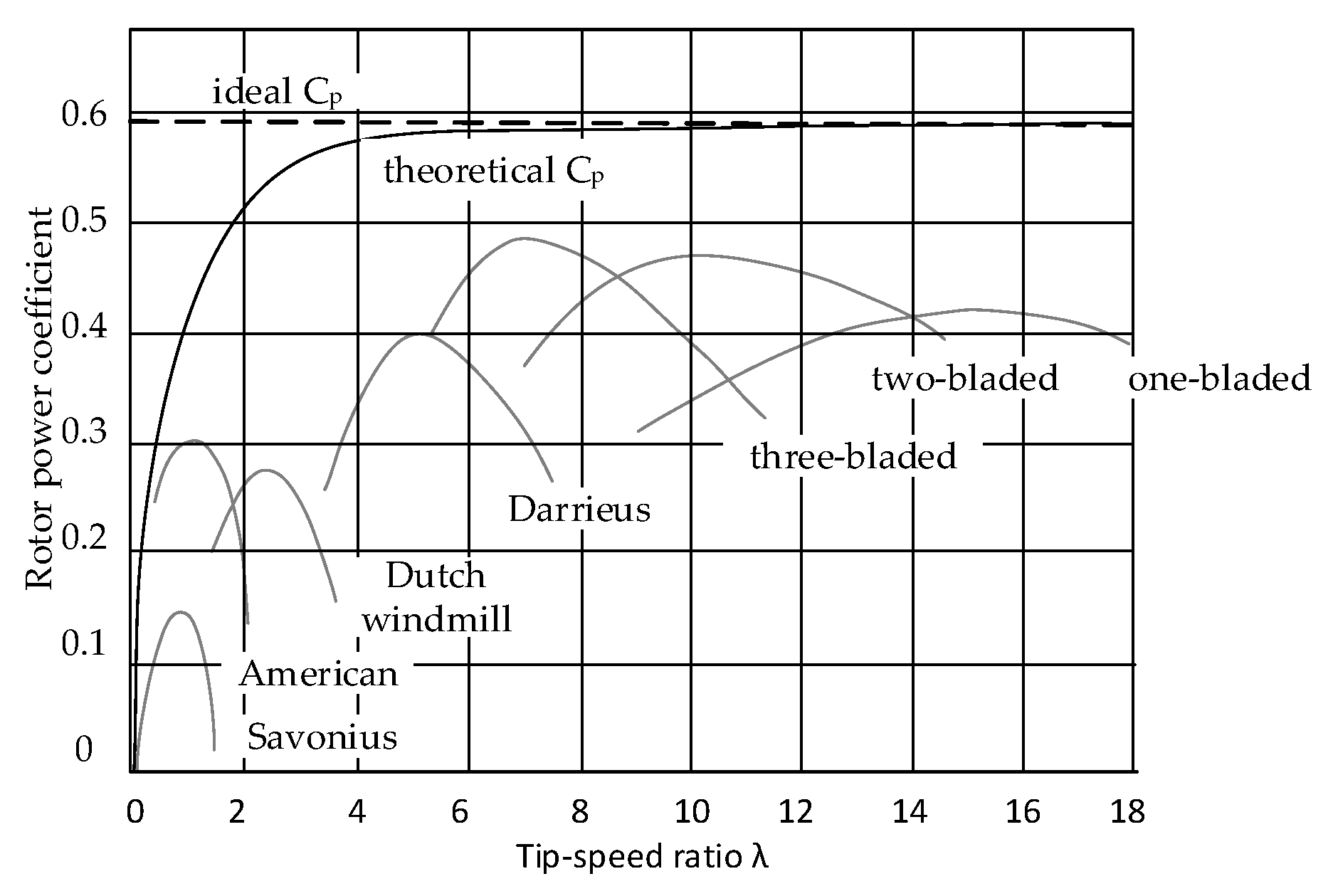
Figure 1. C p coefficient depending on the type of rotor and tip speed ratio [13].
Energies 18 04082 g001
Figure 2. Examples of configurations of superconducting synchronous generators used in wind turbines [60].
Energies 18 04082 g002
Figure 3. Different design approaches for PMSGs: (a) PMSG with single stator and rotor featuring surface-mounted and interior-mounted permanent magnets [73]; (b) dual-stator pseudo-pole five-phase PMSG [75]; (c) dual-stator embedded-pole five-phase PMSG [75].
Energies 18 04082 g003
Figure 4. Generator configurations with superconducting windings: (a) transverse and longitudinal cross-sections of a generator with LTS rotor winding and a copper stator winding [68]; (b) transverse cross-section and sectional view of an axial-flux claw-pole generator featuring a superconducting stator coil [79]; (c) general layout of a generator featuring superconducting windings on both stator and rotor, with detailed rotor component arrangement [84].
Energies 18 04082 g004
Figure 5. Selected axial-flux machine designs and topologies: (a) topology of a YASA axial-flux machine with an SMC core [90]; (b) design of an axial-flux switched machine with dual outer rotors and a stator containing permanent magnets and copper armature windings [92]; (c) structure of an axial-flux machine with a central rotor and segmented U-core stators with embedded permanent magnets [91]; (d) design of a field-controlled AFPM machine with stator core-integrated DC field winding [93].
Energies 18 04082 g005
Table 1. Description of TRLs.
TRLNameDescription
TRL 1Basic principles observedScientific research begins—basic principles are identified.
TRL 2Technology concept formulatedPotential applications are identified; initial concept of the technology.
TRL 3Experimental proof of conceptAnalytical and laboratory studies confirm the feasibility of the concept.
TRL 4Technology validated in the labBasic technological components are integrated and tested in a laboratory environment.
TRL 5Technology validated in relevant environmentTechnology tested in a simulated or relevant environment.
TRL 6Technology demonstrated in relevant environmentPrototype demonstrated in an environment close to operational.
TRL 7System prototype demonstration in operational environmentPrototype tested in real operational conditions.
TRL 8System complete and qualifiedTechnology is complete and qualified through testing and demonstration.
TRL 9Actual system proven in operational environmentTechnology proven in full-scale use under real conditions.
Table 2. Operational features and technical limitations of synchronous generators in wind turbines.
AdvantagesDisadvantages and Challenges
high efficiency—particularly in PM variants, which minimize energy losseshigher capital cost, particularly for PMSGs utilizing PMs
wide operational speed range—when integrated with power electronic systems, synchronous generators can operate efficiently across a broad range of rotor speedsrequirement for power converters, which increases system complexity and necessitates advanced control strategies
improved power quality—compared to asynchronous generators, synchronous machines facilitate more stable voltage and frequency regulationgreater mass in the case of EESGs, which can pose structural and design challenges in large-scale wind turbines
Table 3. Comparison of advantages, limitations, and application aspects of asynchronous generators in wind turbines in terms of cost, reliability, and grid integration.
AdvantagesDisadvantages and Limitations
simple construction and high reliability—particularly in squirrel cage designs, which are mechanically robust and require minimal maintenancelower efficiency compared to synchronous generators, particularly in squirrel cage configurations
lower cost compared to synchronous generators, making them an attractive choice for less demanding or cost-sensitive applicationsmandatory grid connection (with or without inverter)—they cannot operate in standalone (island) mode without additional equipment
good dynamic performance—DFIGs enable active and reactive power control, allowing better adaptation to fluctuating wind conditionsdependence on power electronics in the case of DFIGs, which increases system complexity and may lead to higher maintenance and service costs
Table 4. Comparison of operational benefits and design challenges of DD wind turbine systems with emphasis on reliability, cost, and technical requirements.
AdvantagesDisadvantages and Challenges
higher reliability—the absence of a mechanical gearbox eliminates one of the most failure-prone components in wind turbinesincreased generator size and weight—the use of large-diameter, multi-pole generators significantly adds to the overall mass of the system
lower operating costs—fewer moving parts result in reduced wear and lower maintenance expenseshigher initial cost—the need for advanced materials (e.g., neodymium magnets) and larger generator structures raises the capital investment
quieter operation—the elimination of the gearbox significantly reduces noise levels, which is especially important for onshore wind installationsrequirement for advanced power electronics—modern inverters and converters are necessary to regulate voltage and frequency, adding complexity and cost to the system
improved efficiency—mechanical losses are minimized compared to geared turbine systems
reduced failure risk under extreme weather conditions—DD systems are frequently used in offshore turbines, where difficult maintenance access makes reliability a critical factor
Table 5. Comparison of the main types of synchronous generators used in high-power wind turbines.
ParameterSuperconducting GeneratorPM GeneratorEESG
EfficiencyHighest (>98%, incl. cryogenic losses)High (~96–97%)Lowest (~94–95%)
MassLowest (very compact for 10 MW class)ModerateHighest
Torque DensityVery highHighModerate to low
Cooling RequirementsCryogenic (20–77 K), complexPassive or air/water coolingAir or water cooling
Use of Critical MaterialsSuperconducting wire (e.g., YBCO, MgB2)Rare-earth magnets (e.g., NdFeB)Copper only
System ComplexityHigh (cryogenics, insulation, monitoring)ModerateLow
Commercial Readiness (TRL)Medium (TRL 6–7)High (TRL 8–9)Very high (TRL 9)
Maintenance RequirementsSpecialized, low frequencyLow to moderateHigh (brushes, field windings)
Offshore SuitabilityExcellent (low mass, high efficiency, modularity)GoodPoor (weight and logistics issues)
Cost (CAPEX)High (materials + cryogenics)High (magnet cost)Lowest (simple construction)
Design FlexibilityHigh (field controllability, compactness)Limited (fixed field from magnets)High (field regulation possible)
Risk of DemagnetizationNone (field generated electrically)Present (temperature, short circuits)None
Commercial status (2025)Prototype (EcoSwing, SupraPower)Commercial (Siemens, GE, Vestas)Commercial (Enercon; mainly onshore)
Table 6. Comparison of selected innovative generators.
No.ReferencePower
[MW]
Speed [rpm]Efficiency
[%]
2 WAP
[t]
Volume
[m3]
Voltage
[kV]
Current
[kA]
3 AG [mm]Losses
[MW]
1[84] SG with MgB210.6109852.494.254.51.4200.2
2[79] Claw-pole101094.518131.73.31.8 0.6
3[22] DD PMSG109.693.0956.4
(all 324.24)
9.873.51.710.7
4[22] med. speed PMSG1048098.41
(1 w.g. 95.8)
12.5
(all 65.03)
(1 w.g. 111.7)
1.6610.40.5520.2
5[22] high-speed PMSG10149898.34
(1 w.g. 96.5)
13.6 t
(all 53.4)
(1 w.g. 100)
1.7510.50.5520.2
6[73] surface PM7129637.151.43.31.370.3
7[73] interior PM71296.740.549.33.31.370.2
8[81] SG
with ReBCO
3.61592 1.21.8130.3
9[76] 4 DSCR PMSG0.6612596.52.450.510.690.6 0.02
10[76] PMSG0.513494.92.690.350.690.420.03
1 w.g.—with gearbox. 2 WAP—Weight of Active Parts. 3 AG—Air Gap. 4 DSCR PMSG—double-stator cup-rotor PMSG.
Table 7. Comparison of different types of generators in the context of their suitability for wind turbines.
Generator TypeCommercialization PotentialTRLKey Implementation ChallengesFuture Development Directions
HTS High (long-term)6–7High cost of HTS tapes and cryogenics; quench risk; lack of operational experience; complexity of cooling systemsCheaper materials (e.g., MgB2); efficient cryogenics; AC loss reduction; standardization and reliability
PM Very high (current market standard)9Cost and supply of rare-earth materials; risk of demagnetization; fixed field strengthRare-earth-free magnets; thermal management; magnet recycling and circular economy
EESGModerate9High mass; lower efficiency; increased maintenance requirementsDesign and weight optimization; use in hybrid or low-cost systems
DFIG High (up to ~5 MW turbines)9Requires grid synchronization; dependence on power electronics; limited scalabilityImproved control systems; enhanced grid fault tolerance; HVDC integration
SCIGLow (for large turbines)9No field control; needs reactive power compensation; low efficiency at variable speedsPotential in simple, low-cost configurations; integration with full-scale AC–DC–AC conversion systems
Disclaimer/Publisher’s Note: The statements, opinions and data contained in all publications are solely those of the individual author(s) and contributor(s) and not of MDPI and/or the editor(s). MDPI and/or the editor(s) disclaim responsibility for any injury to people or property resulting from any ideas, methods, instructions or products referred to in the content.