
Proposal of a Thermal Network Model for Fast Solution of Temperature Rise Characteristics of Aircraft Wire Harnesses

Abstract
1. Introduction
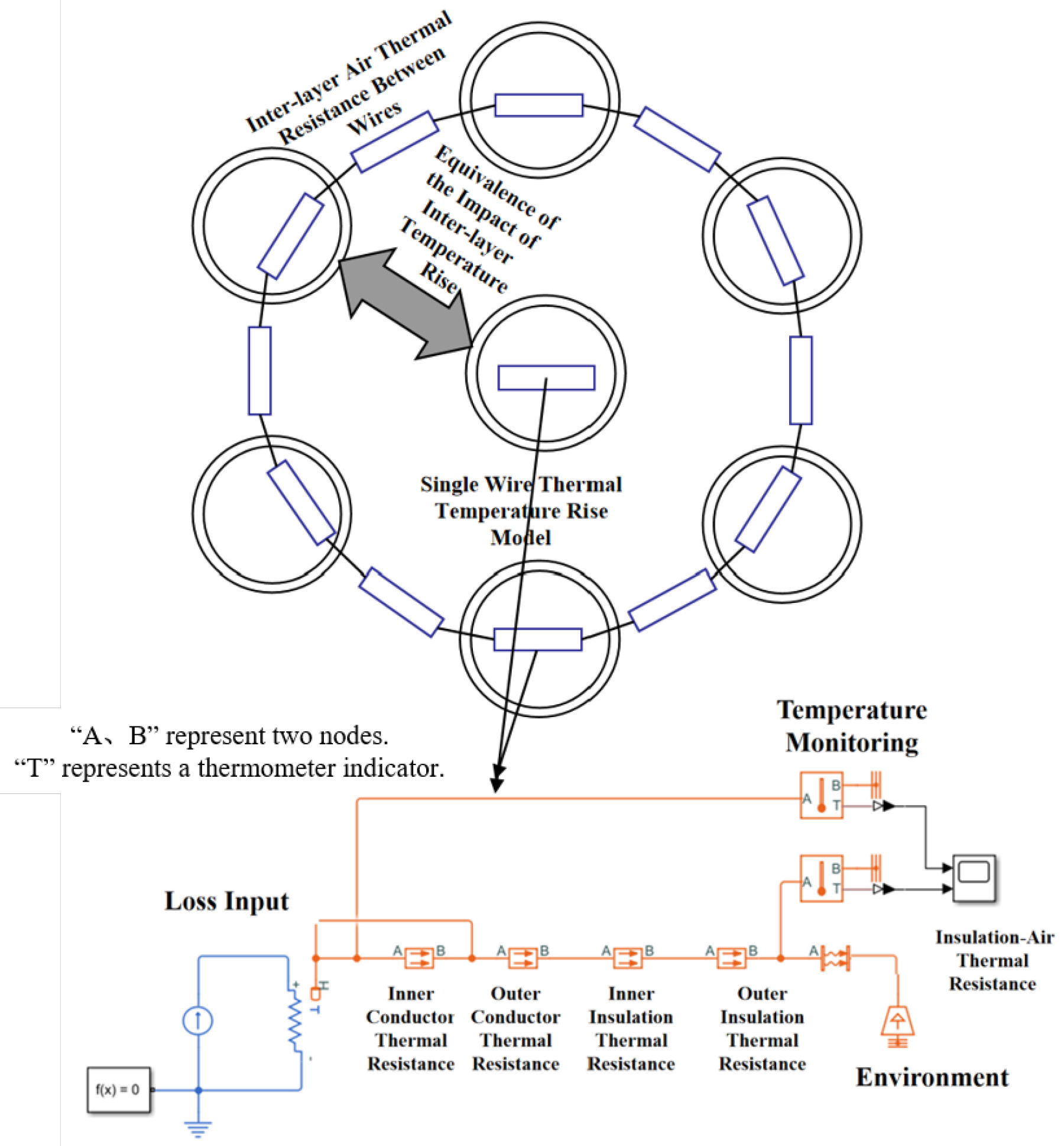
- Establishment of a reasonable precision thermal resistance hierarchical wire thermal network, in which the wire core conductor and insulation layer are divided into inner and outer layers. The model accuracy is corrected through the thermal resistance of the inner and outer layers [25]. Meanwhile, thermal resistance is added between the outer layer of the insulation and the external ambient air to simulate the heat dissipation loss caused by changes in the material properties, thereby improving the model accuracy.
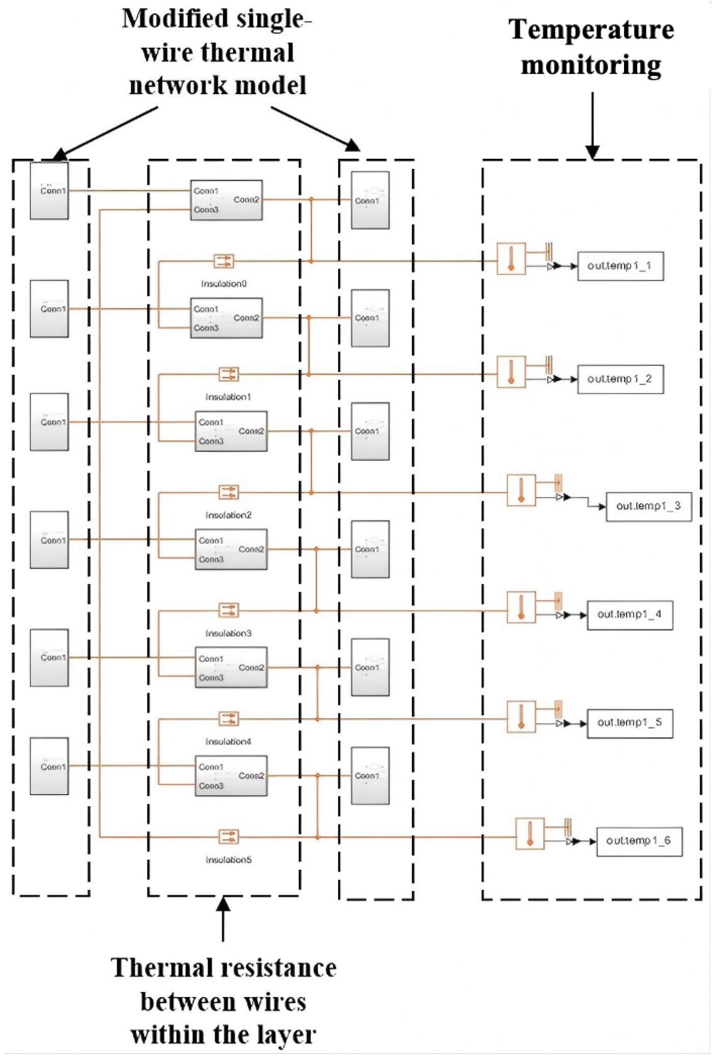
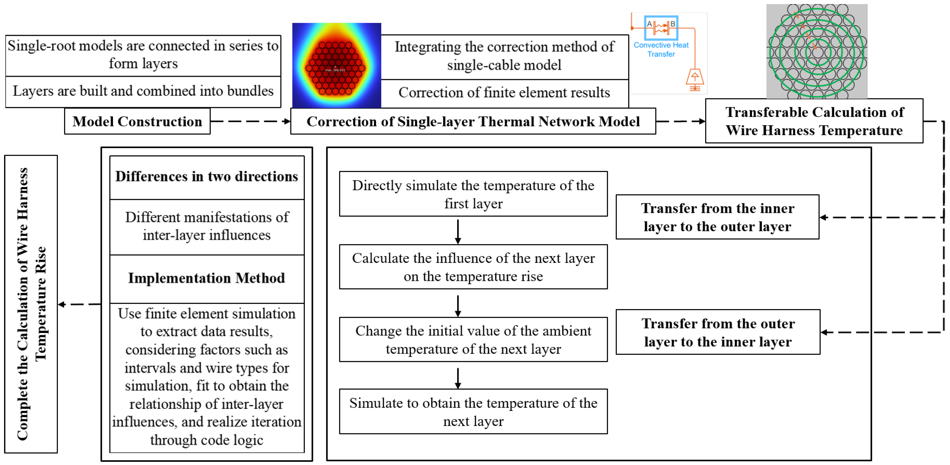
- Construction of a hierarchical harness thermal network model based on finite element model correction—through the topology of the thermal resistance hierarchical wire thermal network, a structure of “series within layers and parallel between layers” is constructed. By conducting power-on simulations on the finite element single-layer model, the convective heat transfer coefficients of each layer’s thermal network model are improved to construct the hierarchical harness thermal network model.
- Hierarchical thermal network iterative calculation method—based on the hierarchical harness thermal network model, the interlayer influence is equivalently constructed through the finite element model results, and the rapid calculation of the hierarchical thermal network model is achieved through the interlayer model iterative algorithm.
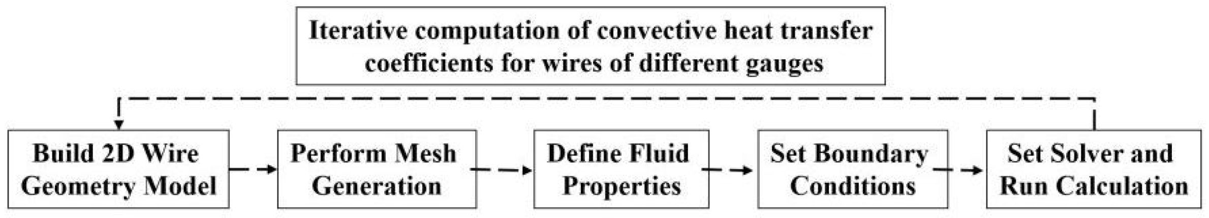
2. Construction of a High-Fidelity Finite Element Model and Determination of the Convective Heat Transfer Coefficient
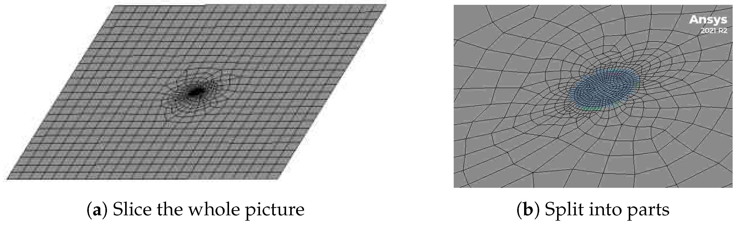
- Modeling and grid generation: create the fluid domain and solid surface, and then use the meshing tool to discretize the geometric model to generate a computational grid suitable for calculating fluid flow and heat transfer. The meshing quality is crucial to the calculation results, directly affecting the calculation accuracy of wire temperature rise. Especially in the boundary layer area, sufficiently fine grids are required to capture the temperature gradient and velocity gradient of the fluid. The finite element grid is shown in Figure 2.
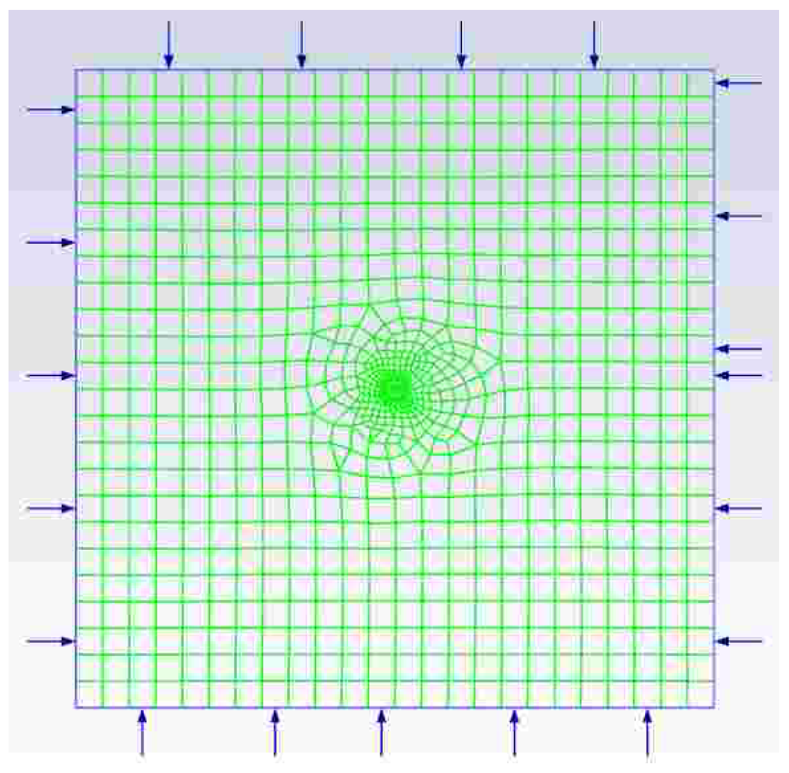
- Setting the boundary conditions of the model: select a suitable laminar flow model or turbulent flow model according to the specific application scenario, and set the inlet boundary conditions and outlet boundary conditions, such as the fixed pressure, flow rate, and ambient temperature. The grid diagram after setting the model boundary conditions is shown in Figure 3.
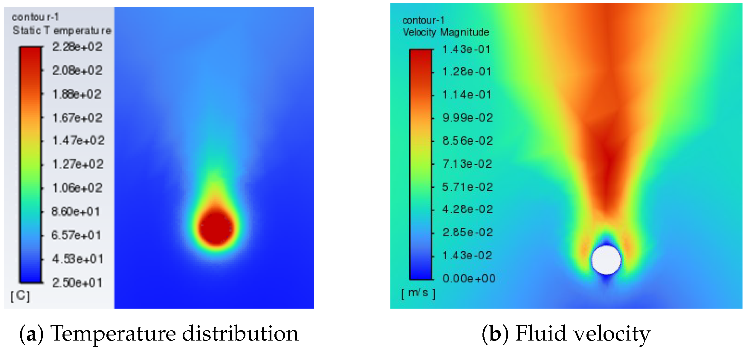
- Setting the solver and calculating: select an appropriate solver and numerical method, and set appropriate convergence criteria for iterative control. The convergence of the calculation process is judged by monitoring the changes in physical quantities (such as flow rate, temperature and residual). After the calculation is completed, check the temperature distribution, velocity field, and heat flux density of the flow field to ensure that the results meet the physical expectations.
- Envelope size limit: according to the installation space requirements, the outer diameter of the wire harness must be kept within a certain range.
- Bending radius limit: the minimum bending radius should be greater than or equal to five times the diameter of the wire harness to prevent excessive squeezing and mechanical damage.
3. Construction of Thermal Resistance Hierarchical Aircraft Wire Thermal Network Mode
- Both the wire and the insulation layer are regarded as uniform and isotropic materials.
- The interfacial thermal resistance between layers (such as the interface between conductors and insulators) is simplified to a concentrated thermal resistance, and local non-uniformity is ignored.
- The temperature distribution at each thermal network node (such as the conductor core and insulation layer) is assumed to be uniform, and the internal gradient is ignored.
- In the steady-state simulation, the convective heat transfer coefficient is set at a constant level, and its variation with the increase in temperature is ignored.
- Since its contribution to the total heat dissipation under operating conditions is less than 5%, radiative heat transfer is ignored.
- An uneven distribution of the wire core and insulation layer. The material properties in the finite element will automatically change with temperature, but the thermal network model cannot consider this change, so the relative error is high. Considering that the wire loss is generated in a three-dimensional body, and heat dissipation ultimately depends on the outer surface of the insulation layer, the larger the diameter, the worse the heat dissipation conditions of the wire and the more uniform the temperature distribution in the wire. Therefore, the larger the diameter, the smaller the error in the thermal network.
- Changes in thermal resistance at the interface between the core and the insulation layer and between the insulation layer and the air layer, as well as a change in materials, which will cause a certain reduction in the wire’s heat dissipation effect. The wire is actually composed of individual cores, and is not a single solid. There are also air gaps between the cores. The traditional thermal network model simplifies the wire conductor into a solid conductor. If each wire core is to be modeled, the thermal network model becomes very complex; therefore, a new model simplification method needs to be created to ensure the accuracy of the calculation results and simplify the model as much as possible. For this reason, in this paper, we create a thermal resistance hierarchical simplified thermal network method for the establishment and calculation of thermal network models.
- To take into account the temperature differences at different positions of the wire, in the modeling of the thermal resistance of the wire layering, the copper core and the insulating layer are, respectively, divided into inner and outer layers. Among them, copper is used as the thermal conductor, and an insulator is used for the insulating layer. This layering treatment divides the geometric boundary through the median diameter. Compared with the air environment, the two are presented as a whole, where the inner layer temperature is relatively higher, and the thermal resistance is specifically increased.
- Thermal resistance is added between the outer layer of the insulation and the external ambient air to simulate the heat dissipation loss caused by changes in the material properties of the insulation and air. At the same time, to simulate the heat dissipation loss due to changes in the material properties of the conductor and insulation layer, the thermal resistance of the outer conductor and inner insulation layer is correspondingly increased.
- During the analysis process, based on the theoretical thermal resistance calculation values of the conductor’s layered structure and in combination with the temperature distribution characteristics observed in actual tests, we empirically adjusted the thermal resistance parameters of each region of the conductor and insulation layer. By comparing the thermal performance data under different line types and working conditions, the correction range for increasing the thermal resistance of the inner conductor by 6.5~8.5% and that of the outer conductor and inner insulation layer by 3.5~4.5% was determined. This correction scheme can better reflect the actual heat transfer characteristics and ensure the applicability of the model to different types of conductors.
4. Aircraft Harness Thermal Network Model
4.1. Construction of a Hierarchical Harness Thermal Network Model
4.2. Interlayer Transferable Fast Calculation Method
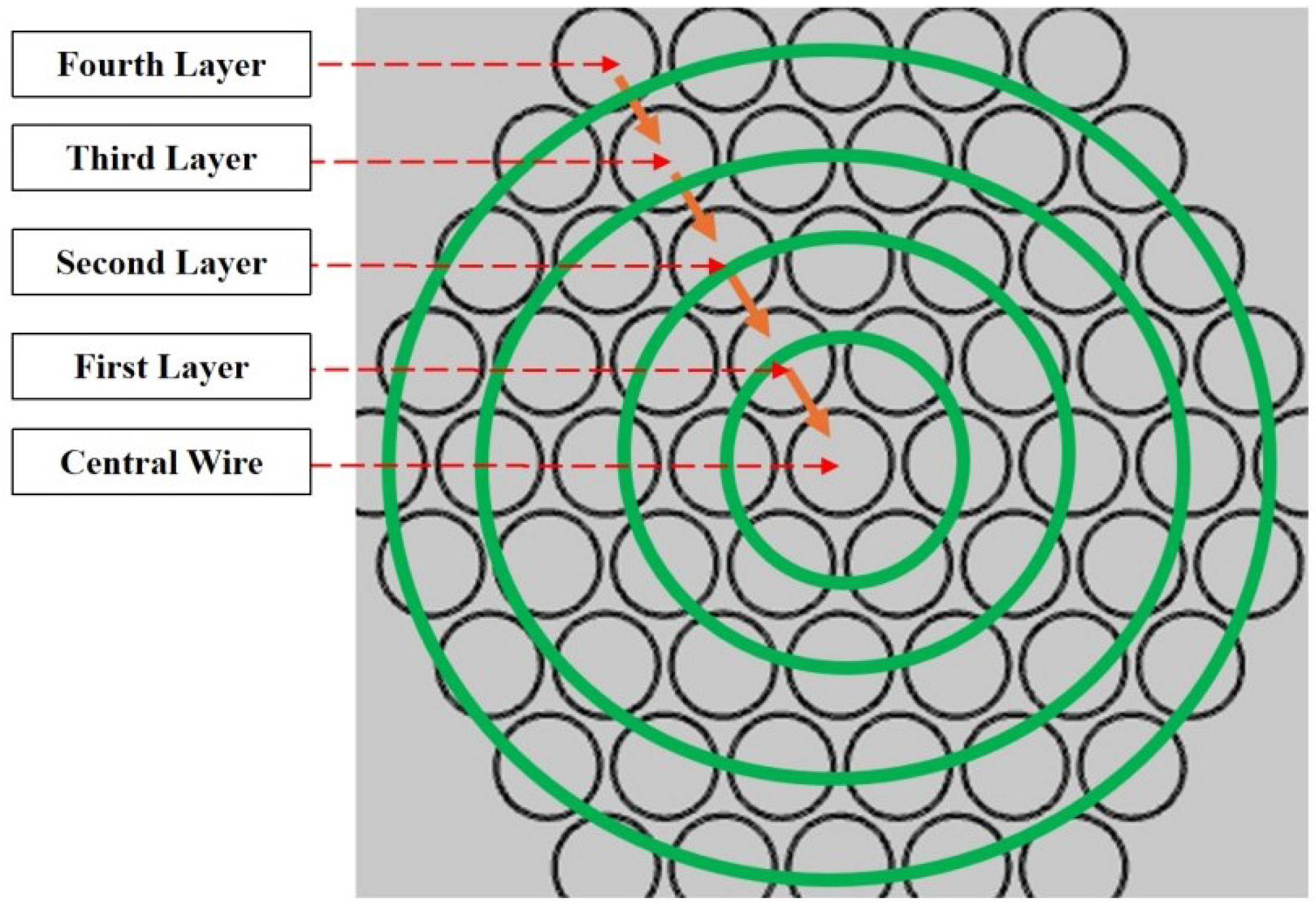
- Transfer calculation from the outside to the inside. A current is applied from the outside to the inside, and the temperature of the outermost layer is first simulated. The outside-to-inside iteration is reflected by overwriting the initial values of the ambient temperature parameters of the inner layer. Since the steady-state temperature is calculated, the temperature influence from the outer layer to the inner layer can be calculated by the average value of the temperatures of two to three adjacent wires. Then, for the next outer layer, the average temperature of the outer layer wires is set as the ambient temperature, and the corresponding current is applied to calculate the temperature of the next outer layer in the first iteration from outside to inside. By repeating until the central wire of the harness is reached, the temperature of this wire of the harness can be obtained.
- Transfer calculation from the inside to the outside. The average value is calculated from the outside to the inside, while the influence of the temperature of the central wire on the outer-layer wires is indicated by the temperature rise transfer from a few wires to many wires, exhibiting a clearer temperature drop. By intercepting the results of multiple groups of finite element simulations, the influence coefficients are fitted into a function of the wire specification, interval distance, and convective heat transfer coefficient as the correction coefficient for the temperature influence of each layer from inside to outside. Then, the iterative process is carried out from the inside to the outside. This influence on the thermal network is reflected in the ambient temperature in the model so as to realize the temperature simulation of the outer layer wires.
4.3. Comparison of Experimental Tests and Simulation Results
5. Discussion
6. Conclusions
Author Contributions
Funding
Data Availability Statement
Acknowledgments
Conflicts of Interest
Abbreviations
| EWIS | Electrical wiring interconnection system |
References
- Hu, X. Research on Electrical Wiring Design and Verification of Civil Aircraft. In Proceedings of the 2022 2nd International Conference on Electrical Engineering and Control Science (IC2ECS), Nanjing, China, 16–18 December 2022; IEEE: Piscataway, NJ, USA, 2022; pp. 96–100. [Google Scholar]
- Crnko, T.; Dyrnes, S. Arc fault hazards and safety suggestions for design and maintenance. IEEE Ind. Appl. Mag. 2001, 7, 23–32. [Google Scholar] [CrossRef]
- Furse, C.; Haupt, R. Down to the wire. IEEE Spectr. 2001, 38, 34–39. [Google Scholar] [CrossRef]
- Spyker, R.; Schweickart, D.L.; Horwath, J.C.; Walko, L.C.; Grosjean, D. An evaluation of diagnostic techniques relevant to arc fault current interrupters for direct current power systems in future aircraft. In Proceedings of the Electrical Insulation Conference and Electrical Manufacturing Expo, Indianapolis, IN, USA, 23–26 October 2005; IEEE: Piscataway, NJ, USA, 2005; pp. 146–150. [Google Scholar]
- Cecchi, V.; Miu, K.; Leger, A.S.; Nwankpa, C. Study of the impacts of ambient temperature variations along a transmission line using temperature-dependent line models. In Proceedings of the 2011 IEEE Power and Energy Society General Meeting, Detroit, MI, USA, 24–28 July 2011; IEEE: Piscataway, NJ, USA, 2011; pp. 1–7. [Google Scholar]
- Cecchi, V.; Leger, A.S.; Miu, K.; Nwankpa, C.O. Incorporating temperature variations into transmission-line models. IEEE Trans. Power Deliv. 2011, 26, 2189–2196. [Google Scholar] [CrossRef]
- Nigol, O.; Barrett, J.S. Characteristics of ACSR conductors at high temperatures and stresses. IEEE Trans. Power Appar. Syst. 2007, 2, 485–493. [Google Scholar] [CrossRef]
- Sellers, S.M.; Black, W.Z. Refinements to the Neher-McGrath model for calculating the ampacity of underground cables. IEEE Trans. Power Deliv. 1996, 11, 12–30. [Google Scholar] [CrossRef]
- Anders, G.J.; Coates, M. Mohamed ampacity calculations for cables in shallow troughs. IEEE Trans. Power Deliv. 2010, 25, 2064–2072. [Google Scholar] [CrossRef]
- IEC 60287-1-1:1994; Calculation of the Current Rating of Electric Cables, Part1: Current Rating Equations (100% Load Factor) and Calculation of Losses, Section 1: General. International Electrotechnical Commission: Geneva, Switzerland, 1994.
- IEC 60287-2-1 AMD 1-2006; Electric Cables-Calculation of the Current Rating-Part 2-1: Thermal Resistance; Calculation of Thermal Resistance; Amendment 2. International Electrotechnical Commission: Geneva, Switzerland, 2006.
- Huang, X. Transmission Line Online Monitoring and Fault Diagnosis, 2nd ed.; China Electric Power Press: Beijing, China, 2013; pp. 69–194. [Google Scholar]
- Henke, A.; Frei, S. Transient temperature calculation in a single cable using an analytic approach. J. Fluid Flow Heat Mass Transf. (JFFHMT) 2020, 7, 58–65. [Google Scholar] [CrossRef]
- Henke, A.; Frei, S. Analytical Approaches for Fast Computing of the Thermal Load of Vehicle Cables of Arbitrary Length for the Application in Intelligent Fuses. In Proceedings of the VEHITS, Online, 28–30 April 2021; pp. 396–404. [Google Scholar]
- Benthem, R.; Grave, W.; Doctor, F.; Nuyten, K.; Taylor, S.; Routier, P.A.J.D. Thermal analysis of wiring bundles for weight reduction and improved safety. In Proceedings of the 41st International Conference on Environmental Systems, Portland, OR, USA, 17–21 July 2011; p. 5111. [Google Scholar]
- Lei, M.; Liu, G.; Lai, Y.-t.; Li, J.-z.; Li, W.; Liu, Y.-g. Study on thermal model of dynamic temperature calculation of single-core cable based on Laplace calculation method. In Proceedings of the 2010 IEEE International Symposium on Electrical Insulation, San Diego, CA, USA, 6–9 June 2010; IEEE: Piscataway, NJ, USA, 2010; pp. 1–7. [Google Scholar]
- Fu, C.; Si, W.; Zhu, L.; Li, H.; Yao, Z.; Wang, Y. Research on the fast calculation model for transient temperature rise of direct buried cable groups. In Proceedings of the 2018 12th International Conference on the Properties and Applications of Dielectric Materials (ICPADM), Xi’an, China, 20–24 May 2018; IEEE: Piscataway, NJ, USA, 2018; pp. 646–652. [Google Scholar]
- Xiao, R.; Liang, Y.; Fu, C.; Cheng, Y. Rapid calculation model for transient temperature rise of complex direct buried cable cores. Energy Rep. 2023, 9, 306–313. [Google Scholar] [CrossRef]
- Liang, Y.; Cheng, X.; Zhao, Y. Research on the rapid calculation method of temperature rise of cable core of duct cable under emergency load. Energy Rep. 2023, 9, 737–744. [Google Scholar] [CrossRef]
- Fu, C.Z.; Si, W.R.; Quan, L.; Yang, J. Numerical study of convection and radiation heat transfer in pipe cable. Math. Probl. Eng. 2018, 2018, 5475136. [Google Scholar] [CrossRef]
- Girshin, S.S.; Bubenchikov, A.A.; Bubenchikova, T.V.; Goryunov, V.N.; Osipov, D.S. Mathematical model of electric energy losses calculating in crosslinked four-wire polyethylene insulated (XLPE) aerial bundled cables. In Proceedings of the 2016 ELEKTRO, High Tatras, Slovakia, 16–18 May 2016; IEEE: Piscataway, NJ, USA, 2016; pp. 294–298. [Google Scholar]
- Zhou, X.; Wen, D.; Wang, S.; Liu, Y.; Jiang, Y.; Li, T. Simulation Analysis of Bundle Conductors Thermal Field in High Voltage Overhead Transmission Lines. Electrotech. Electr. 2017, 3, 20–22. [Google Scholar]
- Yu, X.; Yao, L.; Zhao, S.; Yu, S.; He, A. Infrared On-line Diagnosis Method for the Recessive Defects of Aviation Wire Insulation Layer. Ship Electron. Eng. 2019, 39, 199–203. [Google Scholar]
- Al-Dulaimi, A.A.; Guneser, M.T.; Hameed, A.A.; Márquez, F.P.G.; Gouda, O.E. Adaptive FEM-BPNN model for predicting underground cable temperature considering varied soil composition. Eng. Sci. Technol. Int. J. 2024, 51, 101658. [Google Scholar] [CrossRef]
- Ma, M.; Guo, W.; Yan, X.; Yang, S.; Zhang, X.; Chen, W.; Cai, G. A Three-Dimensional Boundary-Dependent Compact Thermal Network Model for IGBT Modules in New Energy Vehicles. IEEE Trans. Ind. Electron. 2021, 68, 5248–5258. [Google Scholar] [CrossRef]
- ISO 1302:2002; Geometrical Product Specifications (GPS)—Indication of Surface Texture in Technical Product Documentation. International Organization for Standardization: Geneva, Switzerland, 2002.
- Aerospace Standard. Wiring, Aerospace Vehicle AS50881. Available online: https://www.sae.org/standards/content/as50881g (accessed on 17 July 2025).
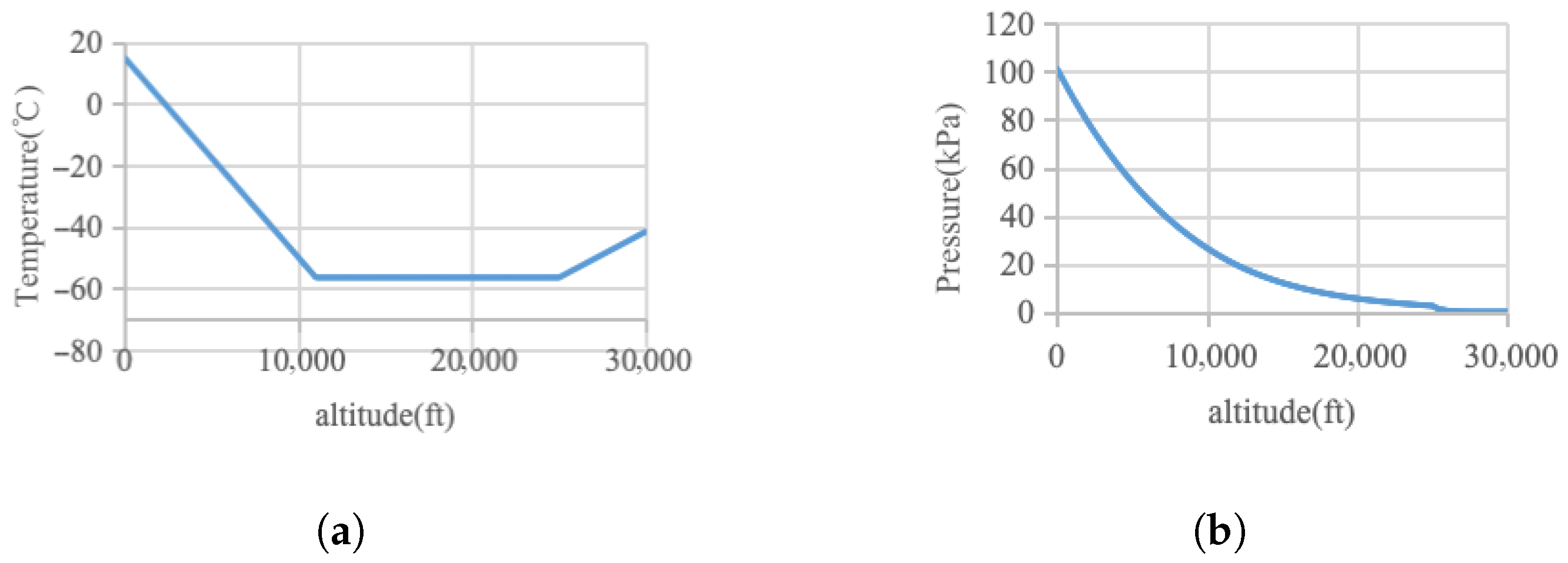
- National Aeronautics and Space Administration. Earth Atmosphere Model. Available online: https://www.grc.nasa.gov/WWW/K-12/airplane/atmosmet.html (accessed on 7 July 2021).


| Wire Gauge | 260 ℃ Experimental Test Current (A) | FEM Simulation Current (A) | Thermal Network Model Simulation Current (A) | FEM Model Error (%) | Thermal Network Model Error (%) |
|---|---|---|---|---|---|
| AWG4 | 284.2 | 288.4 | 269.7 | 1.478 | 5.10 |
| AWG12 | 78.9 | 80.9 | 74.5 | 2.535 | 5.58 |
| AWG20 | 30.0 | 31.8 | 28.3 | 6.000 | 5.67 |
| Power-On Condition | Tested (℃) | FEM (℃) | Thermal Network Model Simulation Current (A) | FEM Model Error (%) | Thermal Network Model Error (%) |
|---|---|---|---|---|---|
| Central 43.66 A | |||||
| Peripheral 0 A | 171.01 | 178.6 | 180.4 | 4.4 | 5.5 |
| Central 43.66 A | |||||
| Peripheral 9.1 A | 260.89 | 268.7 | 271.6 | 3.0 | 4.1 |
| All 10.5 A | 152.86 | 158.5 | 159.4 | 3.7 | 4.2 |
| All 12.3 A | 200.2 | 208.2 | 210.6 | 4.0 | 5.1 |
| All 14.1 A | 257.26 | 268.1 | 269.0 | 4.2 | 4.5 |
| Power-On Condition | Tested (℃) | FEM (℃) | Thermal Network Model Simulation Current (A) | FEM Model Error (%) | Thermal Network Model Error (%) |
|---|---|---|---|---|---|
| Central 38.93 A | |||||
| Peripheral 0 A | 173.82 | 180.5 | 185.2 | 3.843 | 6.56 |
| Central 38.93 A | |||||
| Peripheral 6.2 A | 263.08 | 271.6 | 284.7 | 3.239 | 8.21 |
| All 7.4 A | 150.5 | 155.1 | 161.5 | 3.056 | 7.31 |
| All 8.7 A | 200.7 | 207.9 | 213.5 | 3.587 | 6.38 |
| All 10.05 A | 261.72 | 269.4 | 281.3 | 2.934 | 7.49 |
Disclaimer/Publisher’s Note: The statements, opinions and data contained in all publications are solely those of the individual author(s) and contributor(s) and not of MDPI and/or the editor(s). MDPI and/or the editor(s) disclaim responsibility for any injury to people or property resulting from any ideas, methods, instructions or products referred to in the content. |
© 2025 by the authors. Licensee MDPI, Basel, Switzerland. This article is an open access article distributed under the terms and conditions of the Creative Commons Attribution (CC BY) license (https://creativecommons.org/licenses/by/4.0/).
Share and Cite
Cao, T.; Li, W.; Zhao, T.; Cui, S. Proposal of a Thermal Network Model for Fast Solution of Temperature Rise Characteristics of Aircraft Wire Harnesses. Energies 2025, 18, 4046. https://doi.org/10.3390/en18154046
Cao T, Li W, Zhao T, Cui S. Proposal of a Thermal Network Model for Fast Solution of Temperature Rise Characteristics of Aircraft Wire Harnesses. Energies. 2025; 18(15):4046. https://doi.org/10.3390/en18154046
Chicago/Turabian StyleCao, Tao, Wei Li, Tianxu Zhao, and Shumei Cui. 2025. "Proposal of a Thermal Network Model for Fast Solution of Temperature Rise Characteristics of Aircraft Wire Harnesses" Energies 18, no. 15: 4046. https://doi.org/10.3390/en18154046
APA StyleCao, T., Li, W., Zhao, T., & Cui, S. (2025). Proposal of a Thermal Network Model for Fast Solution of Temperature Rise Characteristics of Aircraft Wire Harnesses. Energies, 18(15), 4046. https://doi.org/10.3390/en18154046