Article

Sensorless SPMSM Control for Heavy Handling Machines Electrification: An Innovative Proposal

1
Department of Phisics, University of Milan, Via Giovanni Celoria, 16, 20133 Milano, Italy
2
Department of Engineering and Architecture, University of Parma, Parco Area delle Scienze, 59, 43124 Parma, Italy
*
Author to whom correspondence should be addressed.
Energies 2025, 18(15), 4021; https://doi.org/10.3390/en18154021
Submission received: 1 April 2025 / Revised: 23 July 2025 / Accepted: 24 July 2025 / Published: 28 July 2025
(This article belongs to the Special Issue Electronics for Energy Conversion and Renewables)

Abstract

The electrification of road vehicles is a relatively mature sector, while other areas of mobility, such as construction machinery, are just beginning their transition to electric solutions. This work presents the design and realization of an integrated drive system specifically developed for retrofitting fan drives in heavy machinery, like bulldozers and tractors, utilizing existing 48 VDC batteries. By replacing or complementing internal combustion and hydraulic technologies with electric solutions, significant advantages in efficiency, reduced environmental impact, and versatility can be achieved. Focusing on the fan drive system addresses the critical challenge of thermal management in high ambient temperatures and harsh environments, particularly given the high current requirements for 3 k W -class applications. A sensorless architecture has been selected to enhance reliability by eliminating mechanical position sensors. The developed fan drive has been extensively tested both on a braking bench and in real-world applications, demonstrating its effectiveness and robustness. Future work will extend this prototype to electrify additional onboard hydraulic motors in these machines, further advancing the electrification of heavy-duty equipment and improving overall efficiency and environmental impact.

1. Introduction

In recent years, there has been a significant shift towards the electrification of vehicles across various sectors [1]. Although electrification of road vehicles is already a well-established field, other mobility sectors are only beginning to explore their transition to electric power. One such sector that stands to benefit greatly from this shift is construction machinery. Replacing or complementing existing internal combustion engines and hydraulic systems with multiple electric machine solutions can lead to notable improvements in environmental sustainability by reducing harmful emissions such as carbon dioxide (CO2), nitrogen oxides (NOx), and particulate matter (PM) to increase overall system efficiency and flexibility and enable the use of advanced control algorithms. Furthermore, replacing hydraulic components with electric systems requires improvements in the reliability of electronic control and drive circuits, ensuring that they meet or exceed the reliability standards of current hydraulic systems [2].
Electric earth-moving equipment is becoming increasingly popular, particularly in urban environments where air quality and noise levels are major priorities. Thanks to their quieter operation, these machines are well suited for environments with strict noise and emissions regulations, including indoor applications. In addition, electric machines typically have fewer moving parts compared with their diesel/hydraulic counterparts, leading to reduced maintenance costs and improved global machine reliability. Furthermore, electric models generally feature fewer moving components than their diesel or hydraulic counterparts, resulting in lower maintenance costs and enhanced overall reliability. Moreover, the shift from full-diesel to electric reduces dependency on fossil fuels, which aligns with the global push towards energy transition and sustainability.
Battery recharging can be achieved via the electrical grid (plug-in) or through dedicated internal combustion range extenders. In the latter case, running the internal combustion engine at its optimal efficiency reduces the environmental impact, even if the primary energy source remains fossil fuel-based.
Another key advantage of electrifying construction machinery is the reduction of noise, thanks to the elimination of thermal or hydraulic components. However, noise can still arise from electric drives, which, despite their lower amplitude, can produce pure tones within the audible range. These sounds can be particularly disruptive and annoying. To address this, in [3] an algorithm to mitigate vibrations caused by cogging torque was explored. This will help prevent the propagation of vibrations throughout the powertrain, reducing operator discomfort and potentially preventing the formation of resonance in the structure, which could lead to fatigue failures or other undesirable outcomes.
It was decided to begin a long and complex process of electrifying excavators, starting with the least critical actuator for the machine’s functionality but most interesting from an engineering challenge perspective: the fan drive for cooling the hydraulic oil in the machines. The fan drive development posed various challenges, especially since the goal was to create an integrated system with the inverter fully embedded within the motor. Legacy hydraulic fan drives are based on hydraulic motors, extremely rugged and compact devices that can easily reach power densities exceeding 10 kW/kg [4], while electric motors only reach about half that figure by means of robust liquid cooling [5]. Reliability is another field in which electric drives are still doing worse than their hydraulic counterparts. While hydraulic motors can have mean times between failures (MTBF) exceeding 1 million h [6], electric machines struggle to reach 300,000 h [7]. Advanced condition monitoring and predictive maintenance techniques are needed to bridge the efficiency gap [8,9].
Electric motors, on the other hand, exhibit higher efficiency than the typical hydraulic motors. While the latter have efficiencies of 70% to 85% depending on the operating point [10], electric drives range from 80% to 95% and above, including losses in both the electronic drive and the electric machine [11], which makes them fit for meeting the challenges related to environmental goals.
It is clear that a growing fraction of endothermic and hydraulic functions in construction machinery will be electrified in the coming years, but the exact timing of the transition and the characteristics of the electrified drives are currently unknown. Electric fan drives can be implemented in different ways, with the main parameters to determine being the rated voltage and power. Electric fan drives for automotive radiator cooling have been on the market for several decades, but their rated voltage of 12 or 24 VDC makes it hard for them to reach even 1 kW of rated power due to the high currents required. If 12 VDC fan drives were used to replace hydraulic fan drives in construction machinery, multiple units would need to be arrayed to reach the desired cooling power.
Fully electrified machines of the future will feature high-voltage (HV) batteries that will enable high-power electric fan drives with manageable current levels. Such solutions are starting to surface on the market for long-term commercial strategies [12], but they still represent only niche implementations as of today.
A halfway point between the 12 VDC and HV implementations is the mild-hybrid approach. A dedicated battery of 48 VDC or 96 VDC can be included to power an increasing number of electrified functions, including fan drives, as a bridge solution towards full electrification, while no HV, high-power battery packs are available onboard. This approach makes it practical to implement multi-kW electric loads. The design proposed here is aimed at a compact, easy-to-install unit, enabling retrofitting [13,14] on existing machines with only a 48 VDC power supply from the onboard lead–acid batteries and a CAN bus communication interface. The inverter needed to withstand high ambient temperatures (up to 80 °C) due to its close proximity to hydraulic circuits; it had to deliver 3 kW of mechanical power with phase currents reaching approximately 100 A and operating in both directions up to 3000 rpm.
The thermal management of the inverter is a rather delicate issue. Given the relatively small size and high efficiency of the drive, it is possible to rely on air cooling only, provided by the fan blades. Specifically, thermal contact shapes have been created on the back motor cover that, through a conductive pad, thermally connect the power devices, extracting heat from the top of the inverter and transferring it to the finned motor cover, which is exposed to forced airflow. For the long-term challenges regarding the full powertrain electrification, liquid cooling is necessarily required, but considering the higher efficiency, it can be significantly reduced compared with traditional machines.
To implement a thermal protection strategy, a temperature sensor is placed near the power devices; in case of overtemperature of the inverter, turning off the fan is not possible because it would produce a sudden increase in the temperature of the hydraulic oil. A derating procedure must be implemented: if a first critical temperature threshold is exceeded, the power of the fan is reduced as well as the power required by the machine’s hydraulic system, lowering the heating of the hydraulic oil. This helps to stabilize the hydraulic oil temperature. If this strategy does not lower the temperature, it is possible to further reduce the power of the fan to avoid reaching a second overtemperature threshold of the inverter, which would otherwise lead to the fan’s permanent shutdown.
The speed reversal is very important because it is periodically necessary to reverse the airflow to clean and purge the entire cooling system of dust and dirt. This task is very simple to perform with an electric drive; conversely, traditional hydraulic systems achieve this function with a very high complexity architecture of valves [4] to reverse the oil flow path and with strategies such as varying the pump displacement to adjust the speed. Furthermore, to enhance system reliability, it was decided to eliminate the position/speed sensor and implement a sensorless control.

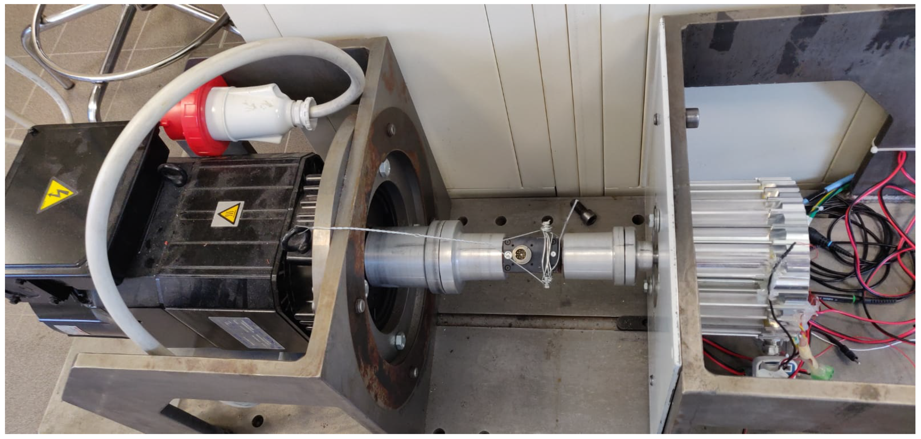
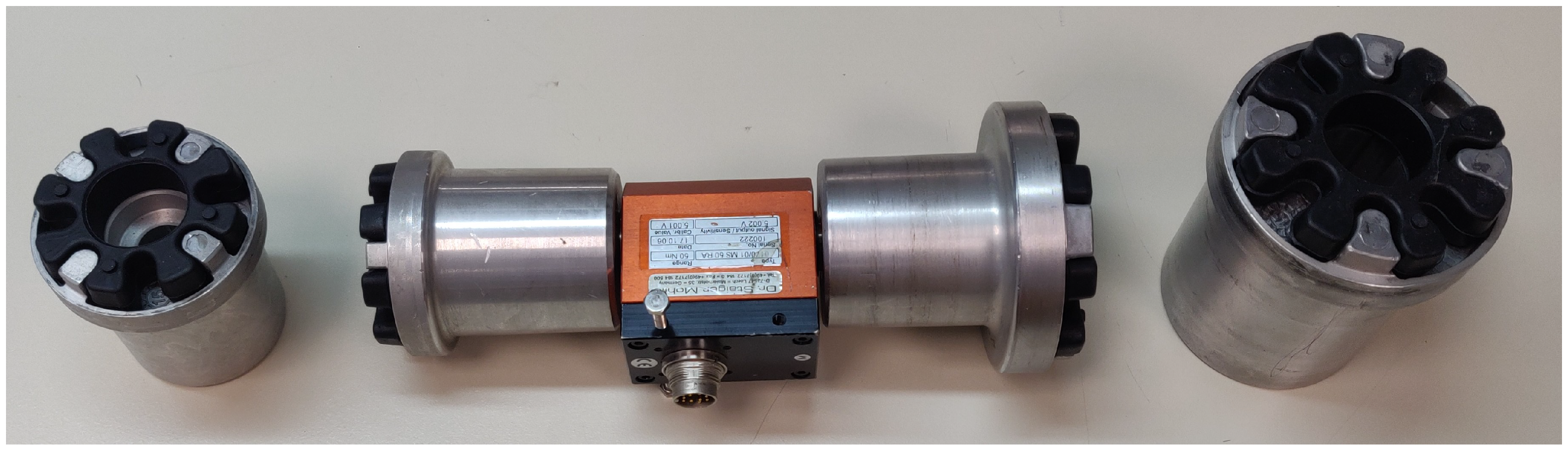
2. Hardware Architecture

The three-phase bridge inverter was designed using the STMicroelectronics (Amsterdam, The Netherlands) ARM Cortex STM32G473 microcontroller, the ON Semiconductor (Scottsdale, AZ, USA) FDBL86062-F085 MOSFET devices, and the STMicroelectronics (Amsterdam, The Netherlands) L6498LD gate drivers with bootstrap architecture. Current sensing was performed using shunt resistors in series with the low-side switches in order to avoid high common-mode voltages on the measurement amplifiers. The same PCB hosts the microcontroller, gate drivers, power MOSFETs, analog signal conditioning circuits, CAN bus transceiver, and a primary buck converter from 48 V to 17 V for the MOSFETs gate control. A secondary buck converter steps down from 17 V to 5 V for the digital logic power supply, and an LDO regulator converts from 5 V to 3.3 V for analog logic and microcontroller power. The main requirements are the round form factor to be inserted into the motor housing, vibration resistance, handling of high currents, high efficiency to reduce inverter dissipation issues, and specifically, MOSFETs with R d s ( O N ) = 2 m Ω and I d = 300 A at T j = 25   ° C , and the H-PSOF8 package.
The adopted SPMSM motor is a prototype version with the characteristics summarized in Table 1, and with the torque and power curve as in Figure 1.
To test the designed drive, a brake bench (Figure 2) was set up with anti-tear couplings and a torque meter (Figure 3) for measuring torque and calculating motor efficiency, along with LEM (Meyrin, Switzerland) LF-210S hall effect sensors for measuring current on the three-phase line. Table 2 summarizes the technical specifications of the torque meter.

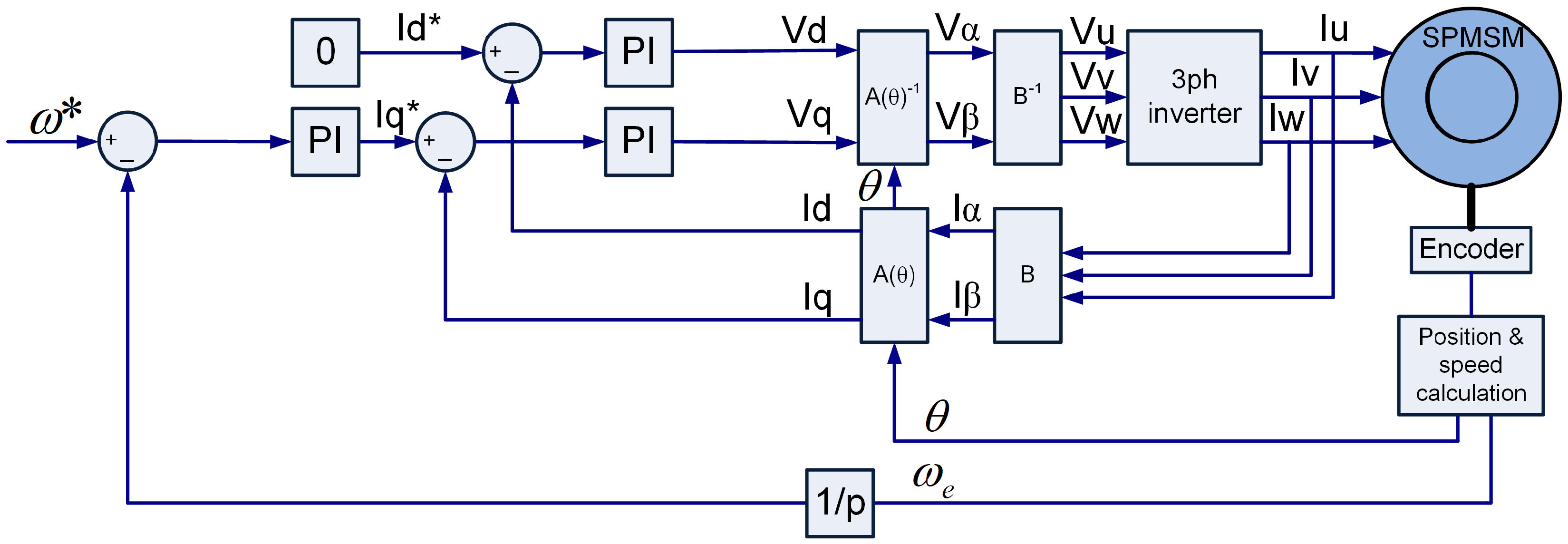
3. Modeling and Control

3.1. Field-Oriented Control Modeling

In this project, a surface permanent magnet synchronous motor (SPMSM) has been used to achieve a high torque density together with a field-oriented control (FOC) (Figure 4) to ensure high efficiency. Moreover, Clarke and Park transformations have been used to simplify the implementation of the control architecture.
The architecture controls the motor using the speed setpoint ω * . Although the physical motor is designed to operate on the classical U–V–W three-phase system, for easier control management, a series of mathematical matrices was used to control the algorithm only by the d–q axes. Using the Clarke matrix [ B ] with a constant ( K B = 2 3 ), it is possible to transform the three-phase fixed vectors quantities U–V–W into a dual-phase orthogonal fixed-axes α - β , maintaining the value of the amplitudes of voltages and currents between the two representations. Moreover, in applications such as those with an isolated star center connection, the homopolar component in the Clarke matrix can be neglected:
[ B ] = K B 1 1 2 1 2 0 3 2 3 2
Using the Park transformation matrix [ A ] , it is also possible to transform the quantities from an α - β fixed-axes representation to a dual-phase quadrature rotating-axes representation dq. This makes it possible to manage constant quantities in stationary conditions.
[ A ( θ ) ] = cos θ sin θ sin θ cos θ
To control the torque generated by the motor, it is important to find the relations between the torque and the electrical variables forced by the inverter, such as current/voltages. Considering the d-q representation of the motor with the Laplace transformation and under the isotropic motor hypothesis ( L d = L q = L e q ) :
v d = R · i d + s · λ d ω e · λ q   ( a ) λ d = L eq · i d + λ m , d ( b ) v q = R · i q + s · λ q + ω e · λ d   ( c ) λ q = L eq · i q + λ m , q ( d )
where v d , v q , i d , i q , L d , and L q are the voltages, currents, and stator inductances, respectively, on the dq axes, and R is the stator resistance. Moreover, ω e is the electrical speed and λ d and λ q are the stator magnetic fluxes generated by the dq currents. λ m , d and λ m , q are the fluxes of the rotor magnets. Considering them not time-dependent, the expression of v d and v q can be rewritten:
v d = R · i d + s · L eq · i d ω e · L eq · i q + λ m , q v q = R · i q + s · L eq · i q + ω e · L eq · i d + λ m , d
The mechanical torque can be expressed:
T = p · λ d · i q λ q · i d
where p is the pole pairs of the motor. Using (3b) and (3d):
T = p · L eq · i d + λ m , d i q L eq · i q + λ m , q i d
Thanks to the alignment of the magnets along the d-axis, the torque results in being proportional only to the current i q and insensitive to i d :
T = p · λ m , d · i q
An algorithm for rotor speed estimation was employed, utilizing a speed observer that estimates the speed using a mathematical model that relies on phase currents measured using shunt resistors.

3.2. PI Control Tuning

Proportional and integral gain values of the speed PI controller were determined by selecting the ratio between the integral and proportional gains through pole-zero cancellation and by extending the bandwidth of the speed control loop by placing the pole at 50 rad/s to find the correct integral gain. To tune the current PI controller parameters, the Ziegler–Nichols method [15] was used, since the motor is designed with windings for low voltages and high currents, which are characterized by extremely low stator resistance and inductance values that are affected by wiring and the positioning of the connection cables, so for that reason the parameters calculated algebraically would be highly unreliable.

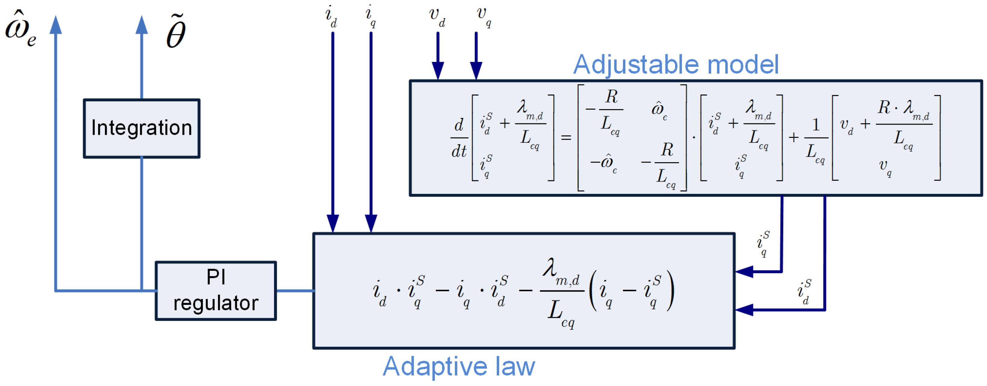
3.3. Sensorless MRAS Algorithm

Some methods for implementing sensorless control have been analyzed, evaluating their pros and cons, particularly from the perspective of embedded industrial applications. The Extended Kalman Filter (EKF) [16,17] is a statistical estimation algorithm that linearizes the nonlinear system around the operating point, then updates the parameter estimates based on the measurement and predictive model. It has high accuracy in speed estimation even in the presence of noise, at low speeds, and during transient conditions. Unfortunately, it has a high computational cost (matrices, derivatives, inversions) and can diverge in the presence of strong nonlinearities or degraded measurement conditions. The Sliding Mode Observer (SMO) [18,19], also known as the Utkin Observer, is also a nonlinear typology and uses sliding mode control to minimize estimation errors, being robust against disturbances and parametric uncertainties. This observer also offers high robustness to disturbances and variations in motor parameters, even at low speeds. However, the system is quite delicate and can generate chattering phenomena (rapid oscillations), requiring filtering or damping. These two models, if the nonlinear system is well-known, are complemented by a linearization process of the entire system, making the speed estimation much more accurate, but this complicates the algorithm’s computation. Finally, the chosen sensorless method, Model Reference Adaptive System (MRAS), was analyzed [20]. It is mainly composed of three blocks: the reference model, the adaptive model, and the adaptive law (Figure 5). The goal of this kind of algorithm is to reach a match between the adaptive model and the reference model through an adaptive law. It has a very low computational cost, making it suitable for applications managed by embedded microcontrollers, and it performs well under steady-state and high-speed conditions without the need for current injection techniques [21]. Additionally, since it is based on linear models, it is robust to small parametric variations. However, it is sensitive to measurement noise, particularly at low speeds, and its effectiveness depends on the quality of the adaptive law.
The adjustable model is composed by the stator current equations, it takes as input the voltages V d , V q estimated starting from the modulation index taking into account the dead time and calculated by the control firmware and the estimated electrical speed ω e ^ coming from the feedback loop. It returns the estimated i d ^ and i q ^ currents on d-q axes.
Instead, the physical motor on d-q axes is chosen as the reference model, it takes as input the currents i d and i q , and as output there is the mechanical shaft speed ω r to be estimated by the algorithm. The adaptive law processes through a mathematical model and a Proportional Integral (PI) regulator both real and estimated currents coming from the adjustable and reference model, returning the motor electrical speed ω e ^ estimation.
Considering the assumption that rotor magnet is aligned along d-axis λ m , q = 0 , the Equation (4) can be rewritten as:
v d = R · i d ^ + s · L eq · i d ^ ω e · L eq · i q ^ v q = R · i q ^ + s · L eq · i q ^ + ω e · L eq · i d ^ + λ m , d
and:
s · i d ^ = R L · i d ^ + ω e · i q ^ + V d L s · i q ^ = ω e · i d ^ ω e · λ m , d L R L · i q ^ + V q L
A mathematical manipulation has to be done: the same factor R L · λ m , d L is added and subtracted from the first equation of (9) to express it in a more practical matrix form:
s · i d ^ = R L · i d ^ R L · λ m , d L + ω e · i q ^ + V d L + 1 L · R L · λ m , d s · i q ^ = ω e · i d ^ ω e · λ m , d L R L · i q ^ + V q L
s · i d ^ i q ^ = R L ω e ω e R L · i d ^ + λ m , d L i q ^ + 1 L · v d + R L · λ m , d v q
To represent the adaptive model in state-space form, the factor λ m , d L has been inserted into the first row of (11). While this term does not affect the mathematical outcome of the matrices, as the derivative of the constant magnetic flux from the magnets is zero, it serves as an essential first step in rewriting the matrix in state-space form.
s · i d ^ + λ m , d L i q ^ = R L ω e ω e R L · i d ^ + λ m , d L i q ^ + 1 L · v d + R L · λ m , d v q
Introducing some ad-hoc fictitious variables i d ^ = i d ^ + λ m , d / L , i q ^ = i q ^ , v d = v d + λ m , d R / L , v q = v q , then
s · i d ^ i q ^ = R L ω e ω e R L · i d ^ i q ^ + 1 L · v d v q
So, to calculate the solution of i d and i q , the two differential equations in (12) have to be solved, but it is not a easy task to be done by a firmware running in a microcontroller with some computational constraints, so, under the assumption that the current slope changes very slowly compared with the sampling frequency, it becomes possible to transform (12) from implicit to explicit form, deliberately committing the mathematical error of treating the explicit current in the first part as if it is found at the current sampling instant n, while for all the implicit currents on the right, values delayed by one sample (n− 1) are used instead. From (12):
s · i d n ^ = R L · i d n 1 ^ + ω e n ^ · i q n 1 ^ + V d n L s · λ m , d L s · i q n ^ = ω e n ^ · i d n 1 ^ ω e n ^ · λ m , d L R L · i q n 1 ^ + V q n L
Afterward, an integration process can be carried out to determine the estimated current values:
i d ^ = t [ R L · i d ^ + ω e ^ · i q ^ + V d L ] d ϵ λ m , d L + c   ( a ) i q ^ = t [ ω e ^ · i d ^ ω e ^ · λ m , d L R L · i q ^ + V q L ] d ϵ + c ( b )
Given the sampled nature of the system, integration has been implemented in a discrete form. Due to the computational limitations mentioned earlier, a basic forward Euler approximation has been employed, as it provides a good balance between functionality and complexity, assuming the signal to be integrated behaves as a slow variable. The starting point is an equation of the following type:
d y d t = a · x ( t ) + b + d z d t
Integrating the equation, an integrative term is obtained that incorporates all contributions from the integrative memory, along with an instantaneous term that has no memory.
y ( t ) = t [ a · x ( ϵ ) + b ] d ϵ + z ( t )
The control is performed using a digital system, where each variable is sampled over time. As a result, the continuous-time equation must be converted into a discrete-time equation, considering that the integral becomes a mathematical summation. By selecting the Euler method with a forward approximation, between two sampling instants (n− 1) and (n) the continuous function is approximated as a constant. This constant value, over the entire sample time, is the value of the function at the (n− 1) sampling time. Each summation factor represents the area of a rectangle, where the base length corresponds to the sample time T s , and the height is equal to the constant value used for approximating the function.
y ( n · T s ) = ϵ = 1 n [ a · x ( ϵ ) + b ] · T s + z ( n · T s )
The value at a certain sample (n) is splitted into
  • Old memory contribution containing the partial sums of the areas under the function until the ( n 1 ) sample.
    y [ n 1 ] = ϵ = 1 n 1 [ a · x ( ϵ ) + b ] · T s
  • Instantaneous memory contribution containing the value of the area under the function between the ( n 1 ) and ( n ) samples.
    T s · [ a · x [ n ] + b ]
  • Contribution with no memory at ( n ) sample that is only taken into account as an instantaneous value and it is not integrated at each cycle.
    z [ n ] = z ( n · T s )
y [ n ] = y [ n 1 ] + T s · [ a · x [ n ] + b ] + z [ n ]
Considering the (15a), the estimated current on d-axis becomes
i d ( n · T s ) = ϵ = 1 n [ R L · i d ^ + ω e ^ · i q ^ + V d L ] · T s λ m , d L
  • Old memory
    i d _ o l d _ m e m [ n 1 ] = ϵ = 1 n 1 [ R L · i d ^ + ω e ^ · i q ^ + V d L ] · T s
  • Instantaneous memory
    i d _ i s t a n t _ m e m [ n ] = T s · [ R L · i d ^ + ω e ^ · i q ^ + V d L ]
  • No memory
    i d _ n o _ m e m [ n ] = λ m , d L
The same process for the estimated current on the q axis, starting from (15b):
i q ( n · T s ) = ϵ = 1 n [ ω e ^ · i d ^ ω e ^ · λ m , d L R L · i q ^ + V q L ] · T s
  • Old memory
    i q _ o l d _ m e m [ n 1 ] = ϵ = 1 n 1 [ ω e ^ · i d ^ ω e ^ · λ m , d L R L · i q ^ + V q L ] · T s
  • Instantaneous memory
    i q _ i s t a n t _ m e m [ n ] = T s · [ ω e ^ · i d ^ ω e ^ · λ m , d L R L · i q ^ + V q L ]
  • No memory
    i q _ n o _ m e m [ n ] = 0
To find the electrical speed information, the real and estimated currents have to be elaborated with an adaptive law and a PI regulator:
ω e = ( K p + K i s ) · ( i d · i q ^ i q · i d ^ λ m , d L · ( i q i q ^ ) )
The discretized integral of the electrical speed has been used to calculate the position information:
a c t u a l _ a n g l e = a c t u a l _ a n g l e + T s · ω e ;
A firmware wrapping and normalization of the position information between −1 to 1 has done in order to correct feed the sine and cosine function used for Park matrix.

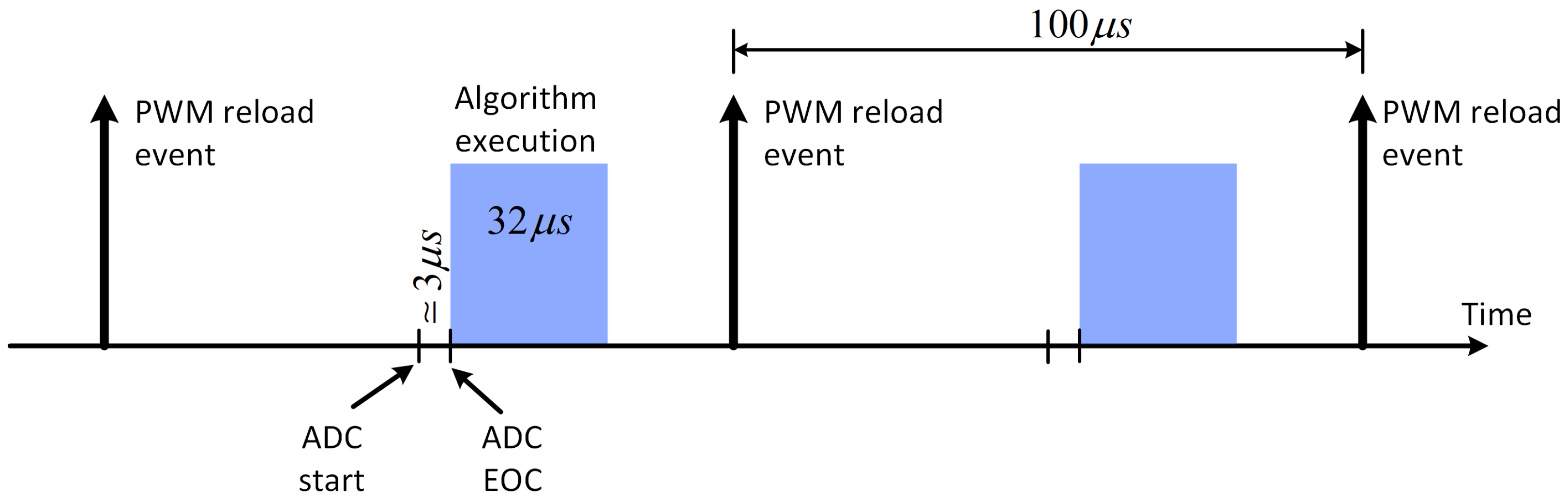
4. Firmware Implementation

The control logic is implemented using a state machine architecture to ensure the correct and safe operation of the motor (Figure 6). At the moment of turning on the system, it moves from the initial state “START” to the main initial waiting state called “STANDBY”.
  • State STANDBY
    It is a standby block where the firmware remains idle, waiting for a start command either from a user button or from an Electronic Control Unit (ECU) command.
  • State ADC CALIBRATION
    Before powering up the inverter, the electronics circuitry for the current and V b u s amplification must be calibrated. To achieve this, 100 samples are averaged for each channel, allowing the determination of a fixed offset that will be subtracted from the current conversion during motor control.
    -
    The state changes to “MOTOR SWITCHING OFF” if a stop command is sent.
  • State CONTACTOR CLOSING
    Before activating the devices of the three-phase inverter, it is essential to send the closing signal to the electromechanical safety contactor. Due to its large size and a current rating of 250 A , the contactor takes a considerable amount of time to close, up to 200 m s . If the contactor were closed simultaneously with the inverter devices, which operate instantaneously with the current loops, a significant current error would occur on the d- and q-axes. This is because no current would flow through the current shunt. As a result, the control system would set the modulation indexes of the motor phases to an excessively high value to achieve the desired current. However, at the moment the contactor physically closes, an instantaneous overcurrent would occur during the first control cycles, before the system can react and lower the modulation indexes.
    -
    The state changes to “MOTOR SWITCHING OFF” if an overcurrent as been detected.
    -
    The state changes to “MOTOR SWITCHING OFF” if a stop command is sent.
  • State ROTOR ALIGNMENT
    As explained in (7) and under the hypothesis of λ m , q = 0 , during motor operation, it is essential to keep the maximum torque angle between the stator and the rotor fields. The Park matrix ensures this by providing current solely on the q-axis, which keeps the magnetic q-axis ahead of the d-axis by 90 electrical degrees. This alignment allows the motor to operate at maximum efficiency and torque density.
    To achieve this, during the initial step of the state machine, a current is applied to the d-axis for a few seconds by imposing a fixed angle in the Park matrix. This helps the rotor mechanically align along the magnetic axis. Once this alignment is achieved, the current rotor position is used as the starting angle. Two different angles are set 3 s apart in order to prevent the rotor from getting stuck due to being randomly aligned in phase opposition with respect to the field on the d-axis. For simplicity, angles of 30 degrees and 0 degrees are chosen.
    -
    The state changes to “MOTOR SWITCHING OFF” if an overcurrent as been detected.
    -
    The state changes to “MOTOR SWITCHING OFF” if a stop command is sent.
  • State ROTOR SYNCRONIZATION
    This state is focused on starting the motor rotation. It is not possible to start the motor directly using the sensorless algorithm because it relies on measuring the back electromotive forces generated on the stator due to the rotation of the magnets. However, at low speeds, these forces are negligible because of the low signal-to-noise ratio. Therefore, the motor start must be driven by generating a fictitious angle through firmware. This angle increases its rotational speed progressively until it reaches a constant speed that is considered reliable enough to switch to the sensorless algorithm. During this spin-up phase, the control operates at low performance and low torque density, as it is not field-oriented control. The angle inserted into the Park matrix does not come from the control feedback block but is a fictitious value, assuming that the rotor will be able to follow it for close the speed loop in the next state.
    -
    The state changes to “MOTOR SLOWING DOWN” if a change in direction is required.
    -
    The state changes to “MOTOR SWITCHING OFF” in case of zero speed request.
    -
    The state changes to “MOTOR SWITCHING OFF” if an overcurrent as been detected.
    -
    The state changes to “MOTOR SWITCHING OFF” if a stop command is sent.
  • State SENSORLESS OPERATION
    This is the main program for normal operation in sensorless mode. Once the motor has completed its acceleration in open-loop mode, the program immediately transitions to this state, where a series of controls and delicate actions take place.
    -
    After making the necessary adjustments, the instantaneous position reached by the motor in open-loop mode is copied and transferred into the sensorless variables. This allows the Park matrix to be controlled by the algorithm itself, and the speed loop is then closed using the estimated speed.
    -
    The estimated speed is analyzed to ensure it meets the minimum acceptable values. If the speed is within the expected range, the motor is considered to be properly started and synchronized with the sensorless algorithm. However, if the motor has lost synchronization, the state transitions to “MOTOR SLOWING DOWN.”
    -
    The acceleration ramps are controlled based on the speed requested by the user, and the direction reversal is handled automatically, managing the entire restart process seamlessly.
    -
    To prevent the overcurrent protection from triggering, the values of the proportional and integral constants, as well as the output saturations of the current PI regulators, are gradually adjusted in 4 steps, with each step occurring every 100 ms.
    -
    Additionally, there is an algorithm designed to appropriately adjust the braking output saturation values of the current PI regulators based on the direction of rotation. This helps prevent excessive braking of the motor, which could cause an overvoltage on the DC bus of the inverter. In cases where there is no regenerative DC source or braking resistor, such an overvoltage could lead to a non-reversible failure of the inverter.
    -
    The state changes to “MOTOR SLOWING DOWN” if a change in direction is required.
    -
    In case of zero speed request the state becomes MOTOR SWITCHING OFF.
    -
    The state changes to “MOTOR SWITCHING OFF” if an overcurrent as been detected.
    -
    The state changes to “MOTOR SWITCHING OFF” if a stop command is sent.
  • State MOTOR SLOWING DOWN
    It is a time frame designed to wait for the motor to slow down before automatically restarting the entire process.
    -
    The state changes to “ADC CALIBRATION” after the slowing down time has elapsed.
    -
    The state changes to “MOTOR SWITCHING OFF” if a stop command is sent.
  • State MOTOR SWITCHING OFF
    It is a time frame to allow for the motor to slow down before transitioning to the STANDBY state.
This state machine is strictly dedicated to controlling the motor’s physics in a stable and safe manner. In case of system integration with a CAN-bus communication, it is good practice to handle them separately with dedicated state machine that should be synchronized in a non-blocking way with the main motor state machine.
The previous described firmware runs on a STMicroelectronics (Amsterdam, The Netherlands) STM32 ARM Cortex-M4, this RISC (Reduced Instruction Set Computer) microcontroller has a built-in DSP instruction set, a single precision Floating Point Unit (FPU), and Direct Memory Access (DMA) feature. Both core and peripherals run at a clock frequency of 170 M Hz , ensuring up to 213 DMIPS (Dhrystone Million Instructions Per Second). Regarding the computational complexity, while the state machine runs on the main, the implemented control runs linked to the Analog to Digital Converter (ADC) End Of Conversion (EOC) Interrupt Service Routine (ISR) at a frequency equal to that of the PWM signals ( 10 k Hz ). This implementation ensures an efficient use of microcontroller resources (Figure 7), since the frequency of execution of the control algorithm is 10 kHz (corresponding to a period of 100 μ s ), and the algorithm is executed in about 32 μ s . The overall CPU usage is about 35 % . An alternative solution to estimate the CPU usage, before the implementation of the code, is the use of the SIL (Software-In-the-Loop) and PIL (Processor-In-the-Loop) paradigms to analyse the combination of control parameters and the complexity of the algorithm [22]. In this way it is possible to estimate the CPU usage and a more correct choice of hardware to use. This kind of analisys is very common in power converter development [23].

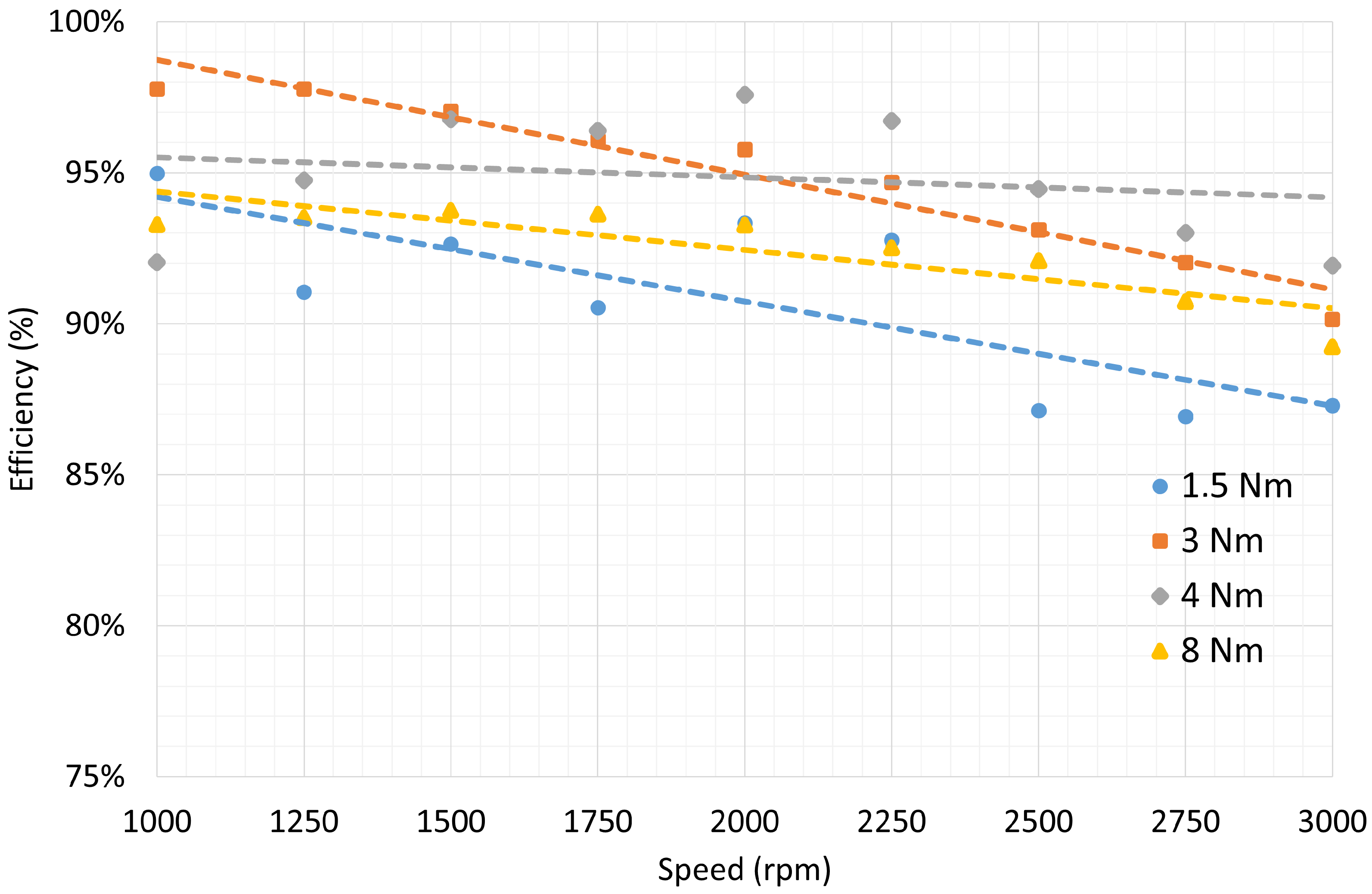
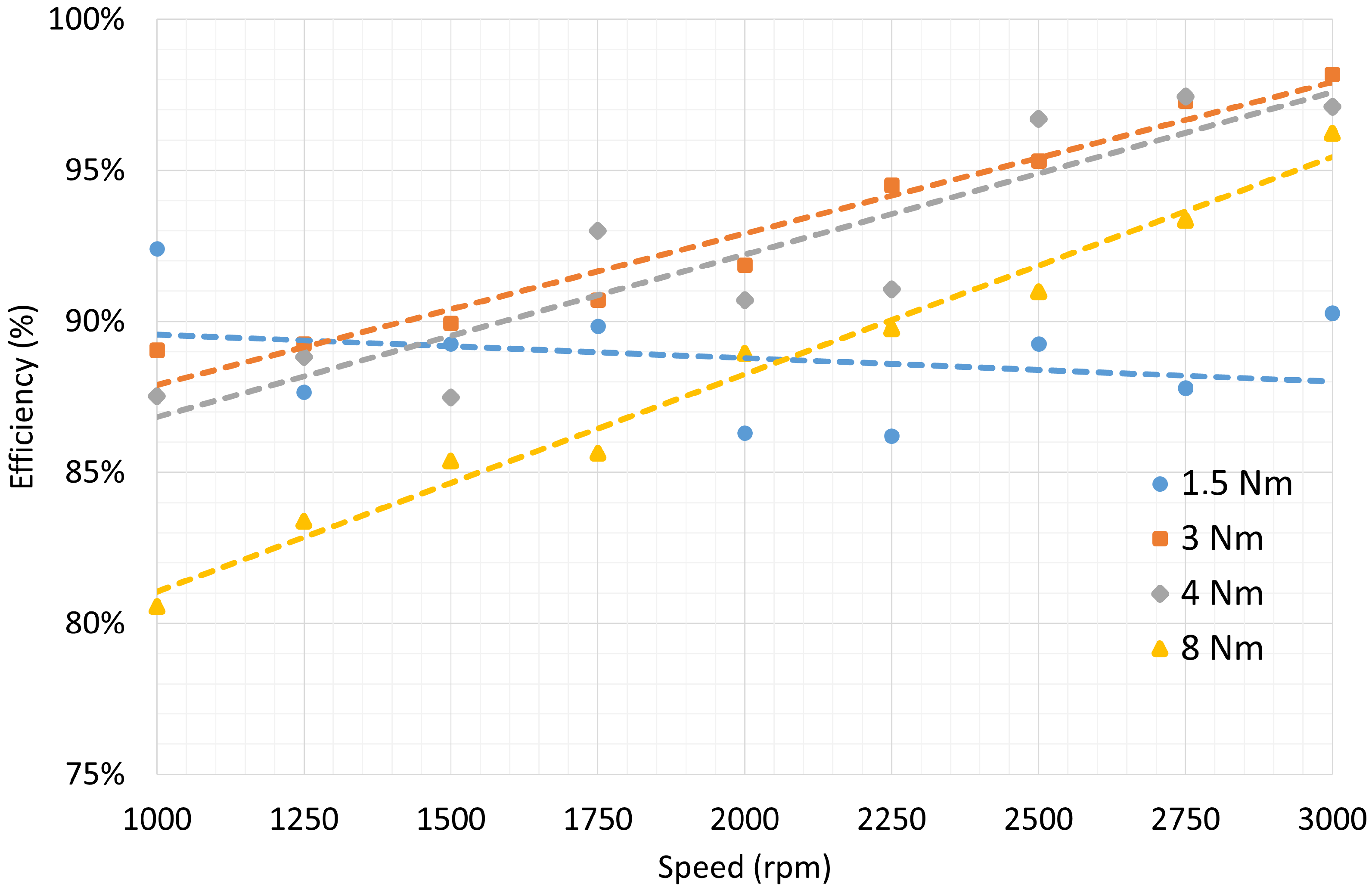
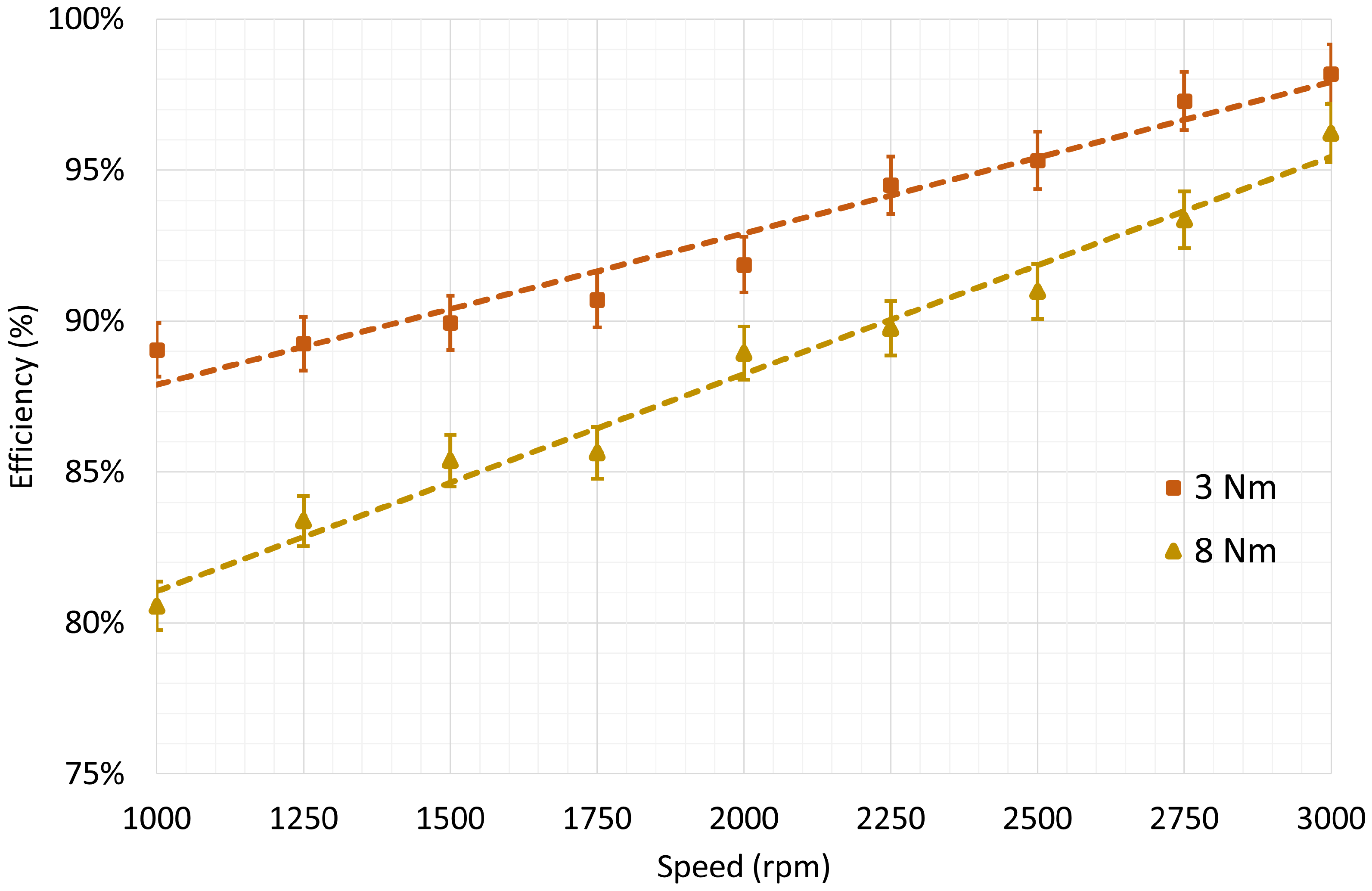
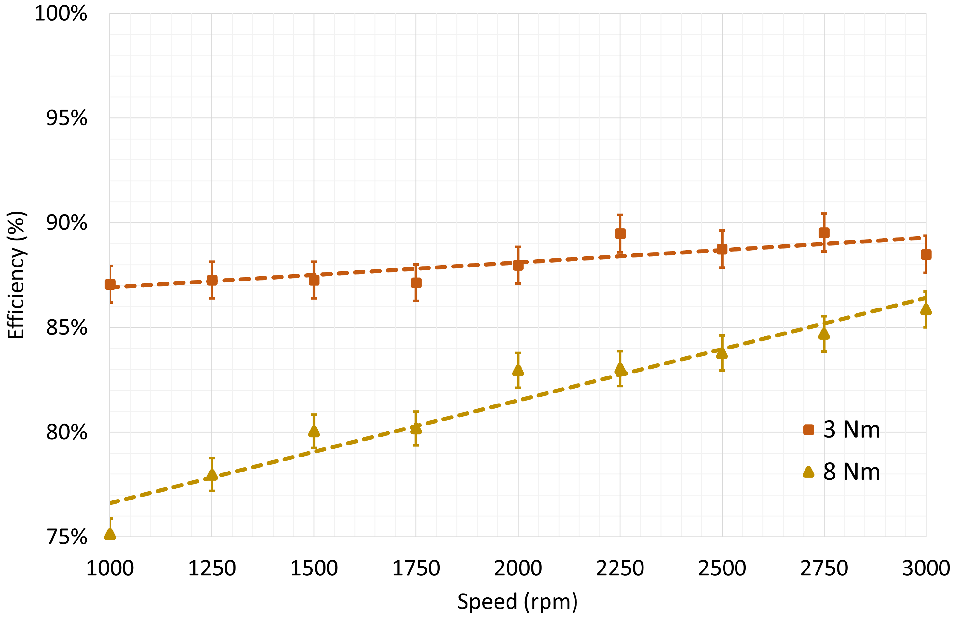
5. Experimental Results

The experimental validation of the developed system concerned first of all the effectiveness of the sensorless control, by means of a comparison between sensorless and sensored algorithm in terms of speed step response in no-load condition. The sensored solution uses an optical encoder as position/speed sensor and an advanced technique to measure the speed [24], and it performs slightly better than the sensorless one, in fact Figure 8 shows a rise time of approximatively t r i s e = 150 ms versus t r i s e = 250 ms for the sensorless algorithm. Note that the response of the sensorless algorithm is quicker at the beginning of the transient, due to the delay in calculating the speed starting from the encoder signal used by the sensored algorithm. As it can be seen the overshoot in the speed step response of less than 5 % was achieved in both cases by careful calibration of the control parameters (Figure 8). Considering the type of application, dynamic performance is not a critical requirement. However, as mentioned before the performance in terms of speed response rise-time (Figure 9) of the sensorless control is still comparable to that of the sensored approach. Table 3 summarizes the comparison.
For the application of our case study, efficiency is particularly important, which is why it has been carefully studied. The efficiency of the inverter (Figure 10) was estimated by computing the ratio between the three phases power absorbed by the motor and the power absorbed from the DC bus. Motor efficiency (Figure 11) was determined as the ratio between the mechanical power delivered to the shaft and the electrical power absorbed by the motor. Both motor and inverter efficiency has been studied for different torque values. The overall efficiency (motor plus inverter) has also been computed, starting from the previous data, and plotted (Figure 12).
As it can be seen from Figure 10, Figure 11 and Figure 12 for a torque of 1.5 Nm the plots are not very meaningful due to the electrical measurements errors for low value of the output power. However, for higher torque values the trends are clear and consistent with the electric motor data nameplate.
Figure 13, Figure 14 and Figure 15 show the efficiency of motor, inverter, and overall, respectively, for a torque value of 3 Nm and 8 Nm. Furthermore, previous plots also show the 1% error bars to better highlight the incidence of measurement errors.
To complete the experimental tests, the motor output power was measured for different values of shaft speed and for different values of load torque. Results are shown in Figure 16.

6. Discussion and Conclusions

The current period is marked by the development of technological solutions aimed at addressing long-standing problems, particularly the pollution caused by various categories of machinery that use internal combustion engines for operation, such as automotive vehicles and heavy machinery. Considering that the automotive sector is now well-established, it was decided to embark on a lengthy and complex process of electrifying excavators.
The first step focused on the least critical actuator in terms of machine functionality but one that presented a significant engineering challenge: the fan drive for cooling the hydraulic oil. The main challenges came from the high temperatures near the oil radiator, the wide speed variations, and the need for compactness and reliability of the integrated inverter-motor system.
The use case was carefully evaluated (i.e., torque applied as a function of speed, without sudden changes), and taking into account the microcontroller’s computational constraints, the decision was made to implement a PI controller. This choice offered an excellent balance between performance and computational complexity. The entire firmware for vector control was developed and written, initially using a speed sensor and later incorporating a rotor position estimation algorithm to enhance reliability. A test bench was created to evaluate the motor, and after three iterations of inverters and motors, the results were highly satisfactory, achieving drive efficiencies of up to 90 % .

Author Contributions

Conceptualization, C.C., M.B. and A.T.; methodology, M.B.; software, M.B.; validation, C.C., M.B. and A.T.; formal analysis, M.B.; investigation, M.B.; resources, C.C. and A.T.; data curation, M.B.; writing—original draft preparation, M.B. and A.T.; writing—review and editing, C.C., M.B. and A.T.; visualization, M.B. and A.T.; supervision, C.C. and A.T.; project administration, C.C.; funding acquisition, C.C. All authors have read and agreed to the published version of the manuscript.

Funding

This research received no external funding.

Data Availability Statement

The original contributions presented in this study are included in the article. Further inquiries can be directed to the corresponding author.

Conflicts of Interest

The authors declare no conflicts of interest.

References

  1. Zhang, B.; Song, Z.; Liu, S.; Huang, R.; Liu, C. Overview of Integrated Electric Motor Drives: Opportunities and Challenges. Energies 2022, 15, 8299. [Google Scholar] [CrossRef]
  2. Lajunen, A.; Sainio, P.; Laurila, L.; Pippuri-Mäkeläinen, J.; Tammi, K. Overview of Powertrain Electrification and Future Scenarios for Non-Road Mobile Machinery. Energies 2018, 11, 1184. [Google Scholar] [CrossRef]
  3. Bassani, M.; Pinardi, D.; Toscani, A.; Manconi, E.; Concari, C. Active Vibration Control via Current Injection in Electric Motors. Electronics 2024, 13, 3442. [Google Scholar] [CrossRef]
  4. Wang, F.; Hong, J.; Xu, B.; Fiebig, W.J. Control Design of a Hydraulic Cooling Fan Drive for Off-Road Vehicle Diesel Engine With a Power Split Hydraulic Transmission. IEEE/ASME Trans. Mechatron. 2022, 27, 3717–3729. [Google Scholar] [CrossRef]
  5. Sudha, B.; Vadde, A.; Sachin, S. A review: High power density motors for electric vehicles. J. Phys. Conf. Ser. 2020, 1706, 012057. [Google Scholar] [CrossRef]
  6. Danfoss Power Solutions. Product Reliability Data (MTTF) for H1P045-280. 2023. Available online: https://assets.danfoss.com/documents/latest/257866/AB159286485026en-000301.pdf (accessed on 12 May 2025).
  7. Tavner, P.; Ran, L.; Penman, J.; Sedding, H. Condition Monitoring of Rotating Electrical Machines; Bibliovault OAI Repository, The University of Chicago Press: Chicago, IL, USA, 2008. [Google Scholar] [CrossRef]
  8. Toscani, A.; Immovilli, F.; Pinardi, D.; Cattani, L. A Novel Scalable Digital Data Acquisition System for Industrial Condition Monitoring. IEEE Trans. Ind. Electron. 2024, 71, 7975–7985. [Google Scholar] [CrossRef]
  9. Toscani, A.; Rocchi, N.; Pinardi, D.; Binelli, M.; Saccenti, L.; Farina, A.; Pavoni, S.; Vanali, M. Low-Cost Condition Monitoring System for Smart Buildings and Industrial Applications. IEEE Trans. Ind. Appl. 2024, 60, 1870–1878. [Google Scholar] [CrossRef]
  10. Miller, M.; Khalid, H.; Michael, P.; Guevremont, J.; Garelick, K.; Pollard, G.; Whitworth, A.; Devlin, M. An Investigation of Hydraulic Motor Efficiency and Tribological Surface Properties. Tribol. Trans. 2014, 57, 622–630. [Google Scholar] [CrossRef]
  11. Lu, S.M. A review of high-efficiency motors: Specification, policy, and technology. Renew. Sustain. Energy Rev. 2016, 59, 1–12. [Google Scholar] [CrossRef]
  12. EMP. FiC-15 HV Fan. 2025. Available online: https://www.emp-corp.com/product/15-inch-high-voltage-fan/ (accessed on 12 May 2025).
  13. Wiik, M.K.; Fjellheim, K.; Suul, J.A.; Azrague, K. Electrification of Excavators: Electrical configurations, carbon footprint, and cost assessment of retrofit solutions. IEEE Electrif. Mag. 2023, 11, 24–34. [Google Scholar] [CrossRef]
  14. Fan, H.; Huang, Z.; Xie, Y. Cost-effectiveness assessment of retrofitting construction equipment for reducing diesel emissions—A life cycle and public health effects perspective. Environ. Impact Assess. Rev. 2025, 113, 107864. [Google Scholar] [CrossRef]
  15. Ziegler, J.G.; Nichols, N.B. Optimum settings for automatic controllers. Trans. Am. Soc. Mech. Eng. 1942, 64, 759–765. [Google Scholar] [CrossRef]
  16. Bendjedia, B.; Chouireb, S. Comparative study between sensorless vector control of PMSM drives based on MRAS, SMO and EKF observers. In Proceedings of the 2023 International Conference on Advances in Electronics, Control and Communication Systems (ICAECCS), Blida, Algeria, 6–7 March 2023; pp. 1–6. [Google Scholar]
  17. Zheng, Z.; Li, Y.; Fadel, M. Sensorless control of PMSM based on extended kalman filter. In Proceedings of the 2007 European Conference on Power Electronics and Applications, Aalborg, Denmark, 2–5 September 2007; pp. 1–8. [Google Scholar]
  18. Zuo, Y.; Lai, C.; Iyer, K.L.V. A review of sliding mode observer based sensorless control methods for PMSM drive. IEEE Trans. Power Electron. 2023, 38, 11352–11367. [Google Scholar] [CrossRef]
  19. Kim, H.; Son, J.; Lee, J. A High-Speed Sliding-Mode Observer for the Sensorless Speed Control of a PMSM. IEEE Trans. Ind. Electron. 2011, 58, 4069–4077. [Google Scholar] [CrossRef]
  20. Wu, J.; Wei, H.; Zhang, Y.; Wei, H. Sensorless vector control of permanent magnet synchronous motor based on model reference adaptive system. In Proceedings of the 2017 3rd IEEE International Conference on Computer and Communications (ICCC), Chengdu, China, 13–16 December 2017; pp. 2879–2883. [Google Scholar] [CrossRef]
  21. Li, Y.; Zhu, Z.Q.; Howe, D.; Bingham, C.M.; Stone, D. Improved Rotor Position Estimation by Signal Injection in Brushless AC Motors, Accounting for Cross-Coupling Magnetic Saturation. In Proceedings of the 2007 IEEE Industry Applications Annual Meeting, New Orleans, LA, USA, 23–27 September 2007; pp. 2357–2364. [Google Scholar] [CrossRef]
  22. Dini, P.; Saponara, S. Processor-in-the-Loop Validation of a Gradient Descent-Based Model Predictive Control for Assisted Driving and Obstacles Avoidance Applications. IEEE Access 2022, 10, 67958–67975. [Google Scholar] [CrossRef]
  23. Dini, P.; Ariaudo, G.; Botto, G.; Greca, F.L.; Saponara, S. Real-time electro-thermal modelling and predictive control design of resonant power converter in full electric vehicle applications. IET Power Electron. 2023, 16, 2045–2064. [Google Scholar] [CrossRef]
  24. Brugnano, F.; Concari, C.; Imamovic, E.; Savi, F.; Toscani, A.; Zanichelli, R. A simple and accurate algorithm for speed measurement in electric drives using incremental encoder. In Proceedings of the IECON 2017—43rd Annual Conference of the IEEE Industrial Electronics Society, Beijing, China, 29 October 2017–1 November 2017; pp. 8551–8556. [Google Scholar] [CrossRef]
Figure 1. Torque and power curve of the adopted SPMSM motor for continuous operation (S1) and intermittent operation (S6, 40%, 2 min).
Energies 18 04021 g001
Figure 2. Brake bench: motor under test (right), brake (left) and mechanical coupling between the two shafts (center).
Energies 18 04021 g002
Figure 3. Anti-tear couplings for connecting the motor under test with the braking motor, and the torque meter for torque measurement.
Energies 18 04021 g003
Figure 4. Sensored motor control.
Energies 18 04021 g004
Figure 5. Sensorless algorithm.
Energies 18 04021 g005
Figure 6. Block diagram of the motor control firmware.
Energies 18 04021 g006
Figure 7. Microcontroller resources usage (CPU usage about 35 % ). Timing of ADC EOC interrupt.
Energies 18 04021 g007
Figure 8. Speed step response comparison of sensored and sensorless control.
Energies 18 04021 g008
Figure 9. Zoom of speed step response comparison of sensored and sensorless control. Dashed lines indicate the 5 % of the step width. Red arrows indicate the last point outside the 5 % band.
Energies 18 04021 g009
Figure 10. Inverter efficiency as a function of the mechanical speed of the shaft for different torque values applied using the braking bench.
Energies 18 04021 g010
Figure 11. Motor efficiency as a function of the mechanical speed of the shaft for different torque values applied using the braking bench.
Energies 18 04021 g011
Figure 12. Overall efficiency (motor plus inverter) as a function of the mechanical speed of the shaft for different torque values applied using the braking bench.
Energies 18 04021 g012
Figure 13. Inverter efficiency as a function of the mechanical speed of the shaft for torque values of 3 Nm and 8 Nm, with interpolation line and 1% error bars.
Energies 18 04021 g013
Figure 14. Motor efficiency as a function of the mechanical speed of the shaft for torque values of 3 Nm and 8 Nm, with interpolation line and 1% error bars.
Energies 18 04021 g014
Figure 15. Overall efficiency (motor plus inverter) as a function of the mechanical speed of the shaft for torque values of 3 Nm and 8 Nm, with interpolation line and 1% error bars.
Energies 18 04021 g015
Figure 16. Motor mechanical output power versus speed for different output torque values.
Energies 18 04021 g016
Table 1. SPMSM nameplate characteristics.
ParameterValueUnit of Measure
Nominal voltage32V
Nominal frequency233Hz
Nominal current58A
Nominal power3000W
Nominal speed3500rpm
Nominal torque8.1Nm
Pole pairs4-
Torque constant0.14Nm/A
Voltage constant8.7V/krpm
Stator resistance8.2
Stator inductance0.032mH
Power factor0.99-
Table 2. Torque meter technical specifications.
Mechanical Basic DataValue
Mechanical overload capacity1.5 × rated torque
Max. speed up to 18 Nm12,000 rpm
Max. speed from 20 to 160 Nm9000 rpm
Max. speed from 250 to 1000 Nm7000 rpm
Angle measurement2 × 360 pulses, 90° displaced, TTL
Protection classIP40
Electrical SpecificationsValue
Accuracy class0.2
Linearity, hysteresis related to nominal value±0.2% of full scale
Voltage output for rated torque±5 V DC
Temperature influence on the zero point±0.15% / 10 K
Temperature influence on the nominal value±0.15% / 10 K
Rated temperature range+5 to +50 °C
Operating temperature range−25 to +80 °C
Electrical connection12-pole Tuchel
Supply voltage11 to 26 V DC, pole-secure
Current consumption1 W
Table 3. Sensorless versus sensored algorithm step response parametersx.
ParameterSensorlessSensoredUnit of Measure
Rise time250150ms
Settling time450175ms
Delay time15060ms
Overshoot43%
Disclaimer/Publisher’s Note: The statements, opinions and data contained in all publications are solely those of the individual author(s) and contributor(s) and not of MDPI and/or the editor(s). MDPI and/or the editor(s) disclaim responsibility for any injury to people or property resulting from any ideas, methods, instructions or products referred to in the content.

