Abstract
This document focuses on the mitigation of subsynchronous resonance (SSR) in doubly fed induction generators (DFIGs) through the application of an effective solution based on the use of a Static Synchronous Compensator (STATCOM) with fuzzy logic. The STATCOM, a static parallel compensator, improved the stability, quality, and reliability of the power supply in distribution systems by optimizing the response to voltage fluctuations. Combined with fuzzy logic, it provided flexible and efficient control, reducing oscillations arising in the system. Two case studies were carried out in which the DFIG and the STATCOM module with fuzzy logic were implemented in IEEE 13- and IEEE 33-bus systems. Comparative analyses with and without compensation were performed to assess the system’s behavior in response to oscillations generated by the generator, taking voltages as the main variable. The results showed that the fuzzy–PI controlled STATCOM effectively stabilized voltage profiles, mitigating SSR and improving system reliability. In the IEEE 13-bus case, voltage oscillations were reduced by approximately 72% and the bus voltages converged to 0.99–1.01 p.u. within 1.5 s. In the IEEE 33-bus system, the controller achieved a suppression rate of 68%, with voltages restored to 0.98–1.02 p.u. in less than 2 s. These findings demonstrate the efficiency of the proposed fuzzy–PI STATCOM in suppressing subsynchronous oscillations and enhancing stability in DFIG-based networks.
1. Introduction
The increasing development of renewable sources of energy has made wind energy one of the most critical technologies of the energy transition [1,2]. Within wind energy conversion systems (WECS), the most widely used is the doubly fed induction generator (DFIG) because of its efficiency, low cost, ease of deployment, and ability to operate at variable speeds, especially in offshore wind farms where compliance with strict requirements of the grid code is critical [3,4]. Regardless of the benefits mentioned above, DFIG-based wind turbines face stability problems when integrated with series-compensated transmission and distribution networks that can exhibit the subsynchronous resonance (SSR) phenomenon. As noted in [5,6], the SSR describes the coupling of the mechanical torsional components of the turbine-generator shaft with the electrical grid, which leads to oscillations at the frequencies of the sub-grid. This coupling has the potential to induce shaft wear, enhanced mechanical strain, and dynamic instability [7,8].
Within the last ten years, there have been multiple attempts to mitigate SSR. Devices within the FACTS family, such as the STATCOM, SVC, GCSC, and UPFC, have been used to damp oscillations and improve system stability [9,10]. Among these devices, the STATCOM is the most robust, as it possesses the fastest dynamic response, improved voltage control, and is tuneable when coupled with modern control algorithms [11,12].
Contemporary works have centered on the intelligent control STATCOM-based SSR mitigation for DFIG systems. Fuzzy Logic Controllers (FLC), hybrid controllers such as fuzzy–PI, Fuzzy PID, Fuzzy/LQR, and ANFIS have shown improvement in effectiveness when compared to classical PI and PID controllers in terms of response time and system robustness [13,14,15]. ANFIS controllers, for instance, have been shown to achieve settling times of 4–6 s [16] and fuzzy controllers have been able to reduce voltage ripple by as much as 60% boost system performance [17]. Additionally, with the use of wide-area measurement systems (WAMS), SSR mitigation performance has been shown to improve even with communication delays [18].
Nevertheless, the majority of works in the literature have focused on the transmission-level IEEE benchmark systems (IEEE 1st and 2nd) and paid little attention to distribution-level networks. In addition, most studies are based on a single simulation environment, often Matlab/Simulink, without any method cross-validation, which undermines the credibility of these results. This underscores the necessity of cross-platform, hybrid distribution-level simulation frameworks to enable research on SSR mitigation in distribution networks.
Main Contribution: This study fills the existing literature gaps by creating and testing a STATCOM controller using the Fuzzy PI control strategy for the subsynchronous resonance (SSR) problem in wind energy systems based on doubly fed induction generators (DFIGs). The controller is tested in the IEEE 13-bus and IEEE 33-bus distribution networks, which represent benchmark scenarios that have been sparingly investigated in the context of SSR. A hybrid modeling approach is used, combining Matlab/Simulink (2024b) for detailed electromechanical and control system modeling with DIgSILENT PowerFactory (2022) for precise power flow and parameter extraction calculations of the network. Through dynamic response comparison of the system with and without the fuzzy–PI controller, we show that the controller not only improves steady-state voltage stability to within 1 p.u, but it also effectively suppresses subsynchronous oscillations. At the same time, the research situates these findings within contemporary developments in fuzzy logic control design for FACTS controllers, thereby expanding the practical scope and insight for SSR mitigation at the level of distribution networks.
This dual-platform, distribution-focused evaluation of a fuzzy-enhanced STATCOM fills a notable literature gap and provides a foundation for future implementation in real-world wind energy systems.
2. Literature Review
Induction generators have been a growing challenge with the massive integration of wind farms into electrical systems, especially in systems with series compensation. Over the years, several techniques have been used to mitigate this phenomenon.
FACTS devices have proven to be effective solutions for mitigating subsynchronous resonance. These include elements such as the static synchronous compensator (STATCOM), the static var compensator (SVC), the capacitor-controlled series capacitor (GCSC), the unified power flow controller (UPFC), and the series static synchronous compensator (SSSC). These elements are responsible for manipulating the internal control to modify the network impedance, thus dampening the SSR frequency without interfering with its main functions [9].
Several studies have validated the ability of these devices to stabilize electrical power systems, thus fulfilling their main objectives [5]. Power plants are generally located far from the grid or local loads. Long transmission lines increase net reactance, thereby reducing the short-circuit ratio, which results in a weaker grid [19,20]. This can lead to the phenomenon of steady-state SSR, which can be mitigated by enhancing the AC system’s resistance through the introduction of a voltage source converter and a high-voltage DC line (HVDC).
Another technique employed is active disturbance rejection control (ADRC), a nonlinear control method characterized by high adaptability and robustness. To use this technique, the SSR frequency and its influencing factors are analyzed, highlighting the limitations of traditional phase compensation-based controllers. The damping controller then utilizes the ADR method, which adapts to the uncertainty of the SSR frequency. This controller can estimate and automatically adjust unexpected disturbances [21].
Improved controllers based on damping torque have also been used, where the controller is integrated into the d- and q-axis control channels in the internal current loop of the rotor-side converter. On this basis, combined with eigenvalue analysis and particle swarm optimization, the optimal controller coefficients can be determined to maximize the mitigation effect under various system conditions [22].
As mentioned above, there are various techniques and methods to mitigate the SSR phenomenon. Recent advances also include techniques such as synchronous virtual generator control (VSG) [23], fuzzy logic-based control, the use of thyristor-controlled series capacitors (TCSCs), and hybrid optimization algorithms to determine the optimal control parameters, thereby maximizing damping and stability under various conditions. These advances also present new challenges, such as adapting to more complex electrical networks, integrating advanced control algorithms, and improving FACTS devices. The following solutions have been applied in various research projects over the years, Table 1.

Table 1.
Summary of technical solutions, challenges, and comparisons for SSR mitigation.
This review of the literature (Figure 1) reveals that between 2019 and 2024, 33 peer-reviewed publications were published on the mitigation of subsynchronous resonance (SSR) in DFIG systems utilizing fuzzy logic or neurofuzzy STATCOMs. Research output remained low but steady between 2019 and 2021, with a dramatic increase in 2022 as more researchers began to focus on fuzzy logic-based damping methods. The trends in 2023 and 2024 suggest stagnation or a slight decline, indicating a possible stagnation in more traditional case studies, a shift in focus to other areas, or a combination of both. It is essential to note that the overwhelming majority of these studies focus on SSR mitigation at the transmission level, utilizing the first and second IEEE reference systems and performing offline simulations in MATLAB/Simulink. There is a lack of literature on the use of fuzzy PI-controlled STATCOMs in distribution networks, especially IEEE 13- and 33-node systems, and with hybrid modeling tools such as DIgSILENT PowerFactory (v.2023). Our work explicitly fills this gap by applying and analyzing a fuzzy–PI STATCOM in two reference distribution networks, providing a unique combination of detailed simulations and comparative analysis. This emphasizes the originality and significance of our work in a field where most research still overlooks these implementation scenarios.
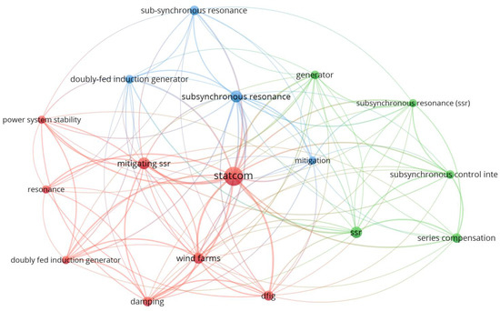
Figure 1.
Research trend showing limited exploration of distribution-grid SSR mitigation using fuzzy-PI STATCOMs.
3. Theorical Framework
3.1. DFIG
The doubly fed induction generator (DFIG) is designed so that the rotor and stator are connected to the grid via independent converters. This generator offers flexibility in connecting to the grid, operating in variable wind ranges and thus making more efficient use of the primary resource [24]. DFIG involves the use of an inverter parallel to the stator that provides control to the rotor circuit under specific operating conditions while extracting additional energy from the rotor [25].
The electric generator is the core of the wind turbine (WT). These are the most common WT generators due to their flexibility in operating over a wide speed range with high efficiency, thereby generating energy at both supersynchronous and subsynchronous speeds [26]. The electrical model of the DFIG in the synchronous frame (with Park’s transform as given previously) comprises the stator/rotor voltage equations, flux linkages, electromagnetic torque, and the mechanical dynamics:
where is the synchronous electrical speed and is the slip angular frequency. The flux linkages are
with , being the stator/rotor self-inductances and the magnetizing inductance. The electromagnetic torque is
where P is the number of poles. The mechanical equation is
with J being the combined inertia, B el coeficiente viscoso, el torque mecánico del eje y la velocidad mecánica del rotor. The stator instantaneous powers are
These equations provide a consistent basis for the analysis and control design later used for SSR mitigation with the STATCOM and fuzzy logic.
3.2. DFIG Rotor Control
Rotor control in DFIG generates a rotating field at synchronous speed with a frequency output of 50 to 60 Hz. At low wind speeds, when the rotor operates subsynchronously, the control adjusts the rotor’s magnetic field so that it rotates at synchronous speed. In stronger wind conditions, when the rotor mechanically rotates at supersynchronous speed, the control ensures that the rotor’s magnetic field maintains synchronous speed. At subsynchronous speeds, a rotating field is added, while at supersynchronous speeds the rotor’s rotating field becomes negative [25]. A standard vector-control scheme is adopted in the synchronous frame with stator-flux (or grid-voltage) orientation so that the active and reactive power are regulated via the rotor currents. Let be the slip frequency and define the rotor current references from active/reactive (or voltage) set-points:
where and are proportional/PI mappings from power (or voltage) errors to current references under the selected orientation. Inner current loops generate the rotor voltage commands with decoupling terms:
where are feedforward terms derived from the selected orientation (e.g., stator-flux or grid-voltage) that compensate cross-couplings due to mutual inductance . With stator-flux orientation (), active and reactive power can be regulated decoupled via and , respectively, in practice.
up to known constants that depend on , , and . The outer loops (power or voltage/reactive) compute and , and the inner PI current controllers synthesize for the PWM of the rotor-side converter. Transformations follow the Park/Clarke operators stated previously, and the slip is updated online as , Figure 2.
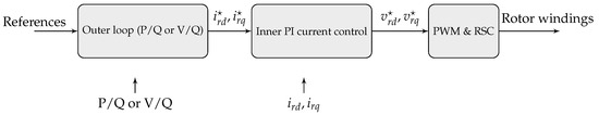
Figure 2.
Compact block diagram of the DFIG rotor control scheme.
3.3. Subsynchronous Resonance (SSR)
This occurs when energy is exchanged between the electrical network and the mechanical turbine-generator system at frequencies lower than the rated frequency, causing torsional oscillations. These are increased by the negative damping of the mechanical system, causing instability and fatigue wear on the turbine shafts [6]. The subsynchronous currents in the system are excited at a specific electrical frequency () due to the series compensation of the line, as shown in Equations (12) and (13).
where
- : Synchronous frequency or fundamental frequency of the system (50 or 60 Hz).
- : Reactance of the series capacitor.
- : Total reactance of the system, including the generator, transmission line, and transformer.
The positive sequence current induced in the stator at the resonance frequency () generates a flux within the stator itself, which results in a current at the frequency :
where
- : Subsynchronous frequency of the rotor.
- : Rotor frequency generated by its rotation.
- : Subsynchronous resonance frequency of the electrical system.
These currents, which can sustain subsynchronous currents in the armature, are generated in the rotor due to the subsynchronous voltage present in the stator due to a subsynchronous frequency. The subsynchronous frequency current produces a torque with a negative damping effect, which can eventually cause a failure in the generator shaft [7].
There are three categories of SSR in DFIG generators, which include the following: the induction generator effect (IGE), subsynchronous control interactions (CI), and torsional interaction (TI) [27]. These are very important and will be detailed below.
3.3.1. Induction Generator Effect
This effect is caused by electrical machines in the grid, without involving the turbine-generator mechanism [5]. Subsynchronous currents create a rotating magnetic field in the stator, and because the rotor rotates faster than this field, it acts as a negative resistance. This causes the generator to self-excite, causing the subsynchronous currents to persist over time [6]. For this reason, it is essential to take into account the slip Formulas (14) and (15) from [8], which can be defined as follows:
where
- : Electrical system frequency.
- : Rotational speed frequency.
The rotor must have a positive resistance , indicating a synchronous state. This state is considered optimal to ensure stable system operation. On the other hand, takes on a negative value, indicating a subsynchronous state. This occurs because the rotation speed frequency () is lower than the natural frequency of the system (), resulting in a rotor resistance with a negative value [28].
3.3.2. Torsional Interaction
This refers to the torsional interactions between electrical networks and the mechanical dynamics introduced by wind turbines. This phenomenon is crucial, as it influences the stability and performance of the systems. The torsional mode frequencies of wind turbines are low, ranging from 1 to 3 Hz, which requires high electrical resonance (57–59 Hz) to interact, something very uncommon given that it requires more than 90% series compensation [29]. If the oscillations of the electrical system align with any of the natural frequencies of the transmission train, this phenomenon occurs. However, this is very unlikely to occur in doubly fed generators (DFIGs) due to the low shaft stiffness involved [30].
3.3.3. Subsynchronous Control Interactions
This is an interaction between any power electronics-based control system (including DFIG control) and the series-connected power grid [23]. In these cases, rapid control of the DFIG converters can exacerbate this phenomenon, thereby generating unstable oscillations at subsynchronous frequencies [27]. These oscillations can be dangerous for the stability of the electrical system and, in some cases, can damage the turbines and affect the compensator. Rotor-side converters (RSC) are important for reducing these oscillations, as they have a greater impact than controllers on the network side (GSC) [31].
3.4. Static Synchronous Compensator (STATCOM)
This is a device used in flexible alternating current transmission systems (FACTS) that compensates for reactive power and regulates voltage by adjusting its output through the incorporation or capture of reactive power to stabilize the frequency when it deviates from the desired value [27,32]. A complete STATCOM system comprises a three-phase voltage converter based on gate turn-off (GTO) devices, a direct current (DC) capacitor, and a step-down transformer with a leakage inductance [10]. The mathematical model is shown below.
where
- : Voltage vector.
- : Current vector.
- T: Transpose operation.
- : Voltage vector at inverter terminals.
- : CD bus capacitor.
- : Series equivalent of the resistances of the two coils of the LCL filter without considering the capacitor.
- : Series equivalent of the inductances of the two coils of the LCL filter without considering the capacitor.
To establish a model of a system connected to the electrical grid, it is easier in practice to transform the electrical variables Vabc into the dq0 system using Park’s transformation.
Model (18) is nonlinear and decoupled, so each of the currents and can be controlled with its corresponding control input and .
3.5. Fuzzy Logic
This is a type of control that allows developers to integrate the ambiguity inherent in human reasoning into computer systems. By using linguistic models instead of purely mathematical models, the clarity of the system is increased and possible modifications are facilitated. This approach is designed to adapt to continuous changes in the variable to be controlled, thus allowing the handling of partial and multi-truth values [33].
The fuzzy logic controller (FLC) is intended to manage the reactive power injection of a STATCOM to mitigate subsynchronous resonance (SSR) for the DFIG-based system. It will be of the Mamdani type since it is easier to interpret and is better for nonlinear control problems. The controller will perform in closed-loop mode with the voltage deviation and its time derivative as control inputs.
3.5.1. Input and Output Variables
Two linguistic input variables are defined:
- E: Voltage deviation from the nominal value (p.u.)
- : Rate of change of the voltage deviation (p.u./s)
The output variable is as follows:
- : Reactive power command to the STATCOM (p.u.).
3.5.2. Membership Functions
For each input variable, seven triangular membership functions are defined: Negative Large (NL), Negative Medium (NM), Negative Small (NS), Zero (Z), Positive Small (PS), Positive Medium (PM), and Positive Large (PL). The output variable uses a similar seven-term fuzzy set. The universes of discourse are normalized to for E and , and for , where is the STATCOM’s maximum reactive capability. Figure 3 illustrates the membership functions.
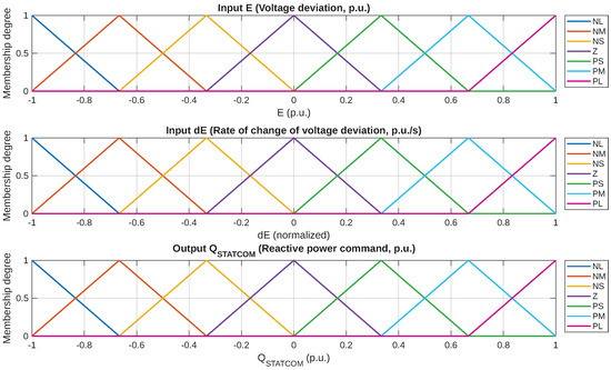
Figure 3.
Membership functions for E, , and .
3.5.3. Rule Base
The fuzzy rule base follows the general structure:
IF E is Ai AND is Bj THEN is Cij.
Table 2 lists the 7 × 7 rule matrix, where the control action is set to counteract the voltage deviation while considering its trend.
Table 2.
Fuzzy rule base for the STATCOM controller.
3.5.4. Inference and Defuzzification
The inference mechanism is Mamdani’s fuzzy inference system based on the min–max composition. The implication method uses the minimum operator for both inference and aggregation; the maximum operator is not used. The defuzzification is done using the centroid method, which yields a smooth control signal.
This fuzzy model provides adaptive and robust control for the STATCOM under these nonlinear and oscillatory conditions, providing for fast voltage restoration and effective SSR suppression.
3.6. Fuzzy Control
The Proportional–Integral (PI) control strategy is preferred over Proportional–Derivative (PD) and Proportional–Integral–Derivative (PID) controls for various reasons. To start, PI control is preferred for power electronic systems and for controlling FACTS devices due to its effectiveness, ease of tuning, and reliability during steady-state and slowly varying dynamic conditions. Unlike PD controllers, PI schemes remove steady-state error without exacerbating high-frequency noise (added in the derivative channel). This feature of PI control is very useful in power networks that operate in the presence of measurement noise. Also, the lack of sensitivity to high-frequency noise due to the absence of the derivative term makes the control less sensitive to rapid changes (switching transients). It eases the tuning of parameters, an advantage for multiple control loops in DFIG-STATCOM systems.
Standard PI control systems struggle to manage system nonlinearities, parameter uncertainties, and fluctuating operating conditions, including those caused by subsynchronous resonance (SSR). To resolve these types of problems, a fuzzy–PI hybrid structure was used. The fuzzy logic component adapts to real-time changes and adjusts error and error rate to eliminate overshoot, providing better control and increased oscillation attenuation. This approach retains the well-studied characteristics of stability and zero steady-state error of the PI controller and, at the same time, incorporates nonlinear mapping and rule-based reasoning of fuzzy logic. Adapting to changes in the system would be slower if a PI controller were used exclusively, and the system would be flexible if a fuzzy controller were used alone. Still, the system could be less predictable with greater computational complexity and less predictable steady-state precision because of the absence of an integral component. The fuzzy–PI structure achieves a good blend of responsiveness, computation, and precision needed to resolve the SSR problem.
Fuzzy logic control is based on the creation of a control law from heuristic and imprecise (fuzzy) rules. The configuration of the fuzzy logic control system used involves several processes. Fuzzy logic control (FLC) contains four main elements: the fuzzification interface, the fuzzy rule base, the fuzzy inference engine, and the defuzzification interface Figure 4 [34].
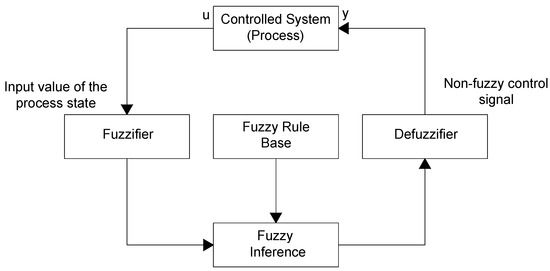
Figure 4.
Fuzzy logic control system architecture.
For the implementation of the fuzzy–PI strategy, Algorithm 1 compiles the entire procedure in a discrete-time simulation framework for the designed STATCOM controller, with a rotor speed sampling time of ms matching the integration step of the MATLAB/Simulink solver. Although this alignment emulates real-time execution in simulation, it does not represent a hardware-in-the-loop or physical implementation. Future work will address the technological aspects required for genuine real-time control, including DSP or FPGA deployment and consideration of communication and detection delays.
Given the angle and speed of the rotor, the STATCOM can modulate its control to respond to and dampen subsynchronous resonance depending on the condition of the grid and the operation of the wind turbine.
| Algorithm 1 Real-time fuzzy–PI control loop for STATCOM damping of sub-synchronous resonance in DFIG systems |
 |
The PI controller parameters were tuned by employing a frequency-response-based technique which targets a specific phase margin and a suitable gain crossover frequency. This method provides a balance between the robustness of the stability and the SSR transient response. For SSR, the proportional gain was adjusted to allow for the necessary bandwidth for voltage regulation. At the same time, the integral gain was set to eliminate steady state error without too much overshoot response. The fuzzy–PI controller inherits these nominal and values as a baseline to be adjusted, but uses a Mamdani-type fuzzy inference system to adapt the gains online according to the instantaneous voltage error and its rate of change. This adaptive adjustment enables the fuzzy–PI controller to provide improved damping performance as the network and operating conditions vary. Such adaptability is particularly useful for counteracting SSR phenomena, which exhibit time-varying dynamic characteristics.
The expected performance criteria for both controllers are summarized as follows:
- Zero steady-state error: Ensuring accurate voltage tracking under nominal and perturbed conditions.
- Low overshoot: Limiting transient overshoot to less than 5% to avoid secondary oscillations.
- Fast settling time: Achieving a settling time below 2 s for voltage restoration after disturbance.
- Effective SSR damping: Reducing the amplitude of sub-synchronous oscillations by at least 50% compared to the uncompensated case.
- Robustness: Maintaining stable operation across varying wind speeds, load levels, and network configurations.
This tuning methodology ensures that the PI controller meets the conventional voltage regulation requirements, while the fuzzy–PI extension provides additional adaptability and damping capability for complex, nonlinear, and time-varying SSR scenarios.
The choice of simulation step sizes was made to ensure both numerical stability and computational efficiency. In Matlab/Simulink, the network and machine dynamics were solved using a fixed integration step of s, which provides adequate resolution for subsynchronous oscillations in the 30–50 Hz range. Meanwhile, the fuzzy PI controller was executed with a discrete sampling time of s. This choice reflects a practical compromise: the solver step is sufficiently small to capture fast electromagnetic transients. In contrast, the controller sampling step is consistent with typical DSP-based implementations and reduces the computational load. Reporting both values ensures reproducibility and allows other researchers to replicate the test conditions accurately.
4. Result and Discussion
4.1. IEEE System Simulations
The proposed method for mitigating subsynchronous resonance has been tested under different scenarios, starting with the modeling of the IEEE 13- and 33-bus systems in Matlab/Simulink without any additional incorporation, together with Power Factory to run the power flows. The simulation times were set at 0.05 s for both systems, allowing three cycles to be displayed in the generated graphs. The initial conditions were configured through the Powergui block, selecting the discrete simulation mode. The sampling time was defined as seconds for the 13-bus model and seconds for the 33-bus model, with both systems operating at a frequency of 60 Hz. Table 3 shows each of these details.
Table 3.
Simulation time and initial conditions in Powergui for Matlab/Simulink.
In a later stage, a DFIG module will be incorporated into the IEEE systems, thus enabling the analysis of subsynchronous resonance. Finally, a last part will be carried out, which will include the implementation of a STATCOM block with fuzzy logic and PI control, facilitating the mitigation of such resonance. The simulations carried out with the new additions will be evaluated and validated through graphical comparisons that illustrate the system’s behavior before and after the implementation of the proposed modules.
Figure 5 shows the block diagram with all the modules that will be implemented in the distribution systems.
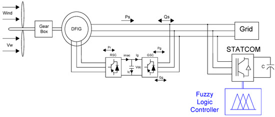
Figure 5.
Block diagram to fuzzy control.
4.1.1. IEEE 13-Bus System
This is an unbalanced system commonly used in the application of computational methods for power flow analysis. It has 13 bars in a radial configuration, where bar 1 acts as a slack node. This system operates at a voltage of 4.16 kV and is represented in the single-line diagram in Figure 6.
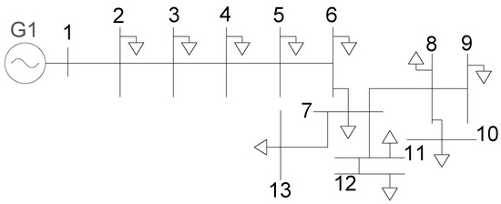
Figure 6.
IEEE single-line diagram with 13 bars.
Table 1 shows the voltage parameters in their normal state without the implementation of any modules. The system voltages, Figure 7, are shown below for busbar 2, which has a voltage of 0.97 p.u. in its normal state.
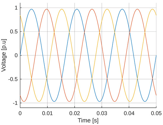
Figure 7.
Voltages on bus 2 of the 13-bus IEEE system. The graph generated is for a three-phase system. The different colors correspond to each phase. Same to the following figures.
4.1.2. 33-Bus IEEE System
This is a standard model used in distribution system studies. It is a radial system operating at a voltage level of 12.66 kV, consisting of 33 nodes. Its configuration includes a slack busbar at node 1, and its single-line diagram is shown in Figure 8.
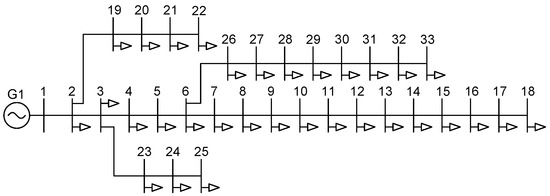
Figure 8.
IEEE 33-bus single-line diagram.
Its voltage parameters are specified in Table 3. Figure 9 shows the voltages of the system in busbar 22, which has a voltage of 0.98 p.u. in its normal state:
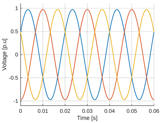
Figure 9.
Voltages on bus 22 of the IEEE 33-bar system.
4.2. Case Studies
This work addresses the refinement of model calibration and cross-platform deployment, which, unlike other studies, does not rely on waveform output from standard simulations. In MATLAB/Simulink R2024b, the electrical, mechanical, and control subsystems of the DFIG model were constructed and tuned, which are validated under different operating conditions. After achieving the desired internal parameters and dynamic response akin to a realistic utility-scale wind turbine, the model was exported and incorporated into DIgSILENT PowerFactory via the Co-Simulation Interface. This enabled the execution of high-fidelity dynamic simulations within realistic IEEE-13 and IEEE-33, also including rigorous fault scenarios. By concentrating on the model’s structural fidelity and the fuzzy–PI STATCOM controller that was embedded within it, the cross-platform benchmarking of the results provided robust scientific evidence from the simulation beyond shallow visuals.
4.2.1. DFIG in the IEEE 13-Bus System
The DFIG module to be implemented is placed on bus 2, as it has a lower voltage than the other buses. Figure 10 shows the system graph when the DFIG module is implemented.
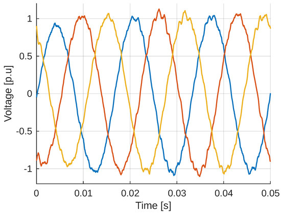
Figure 10.
Voltages with DFIG on bus 2 IEEE 13 buses.
4.2.2. DFIG in the IEEE 33-Bar System
The DFIG module to be implemented is placed on bus 22, as it has a lower voltage than the other buses. Figure 11 shows the system graph when the DFIG module is implemented.
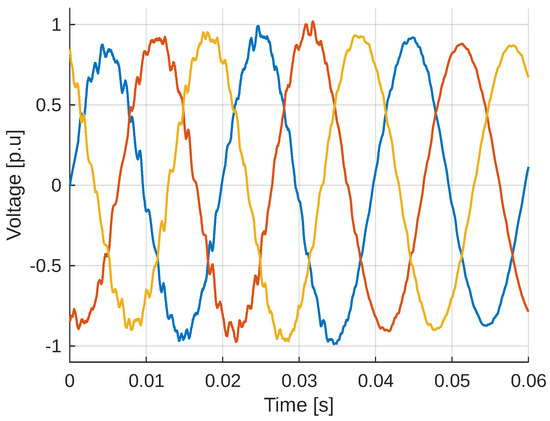
Figure 11.
Voltages with DFIG on bus 22 IEEE 33 buses.
4.2.3. STATCOM Selection and Characterization
The selection and characterization of STATCOMs (Table 4) are essential for studying power systems. This involves selecting the appropriate model from the MathWorks Simulink, MATLAB, or Power Factory library, configuring key parameters such as reactive power capacity and nominal voltage, and then integrating the STATCOM to design a robust control for the system.
Table 4.
Characteristics of 13-bar and 33-bar STATCOM.
4.2.4. Applied Fuzzy Controller Rules
To improve SSR mitigation capacity, the FLC has inputs that include speed deviation and its derivative. and . The inputs ( and ) and the output () are normalized according to defined base values. The rules and number of membership functions that describe the value of the FLC for the inputs and outputs are determined offline. Standard Gaussian membership functions are used for the fuzzy sets of both the inputs and the output.
The control rules are implemented by a representation of a heuristically selected set of fuzzy rules. They were defined as follows:
- N1 ( Negative), P1 ( Positive)
- N2 ( Negative), P2 ( Positive),
- No ( Negative), Zo ( Zero), and
- Po ( Positive).
These rules were arranged as follows:
- If is P1) and is P2), then is Po).
- If is P1) and is N2), then is Zo).
- If is N1) and is P2), then is Zo).
- If is N1) and is N2), then is No).
Additionally, there will be a PI part that helps with fine-tuning regulation based on the parameters set by the fuzzy controller. The procedure for adjusting the PI controller is based on identifying the plant to be controlled, in this case, the model in Simulink. The controller is defined in standard form with values for Kp (proportional gain) and Ki (integral gain). The controller is connected to the plant via a closed-loop system, and its performance is then evaluated by simulating the system response to observe its behavior. Figure 12 and Figure 13 show the membership functions proposed for the fuzzy controller design.
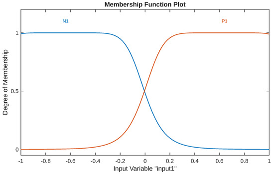
Figure 12.
Membership functions (Input 1: , Input 2: , Output: ).
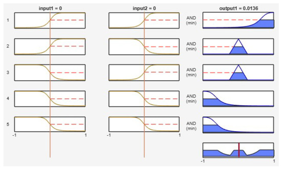
Figure 13.
Graph of fuzzy-controller rules.
4.2.5. Diffuse Controller Work Surfaces
Figure 14, Figure 15, Figure 16 and Figure 17 show the working surface of the fuzzy controller, generated from the rules defined in its configuration. The elevated part indicates a region of stability or maximum control, while the lower blue areas represent areas of lower effectiveness or greater instability.
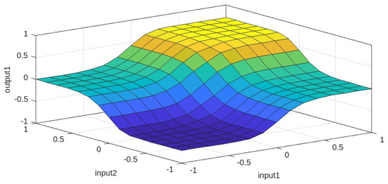
Figure 14.
Working surface of the fuzzy controller (front view).
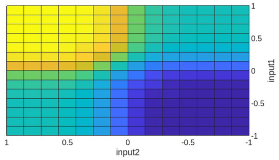
Figure 15.
Working surface of the fuzzy controller (top view).
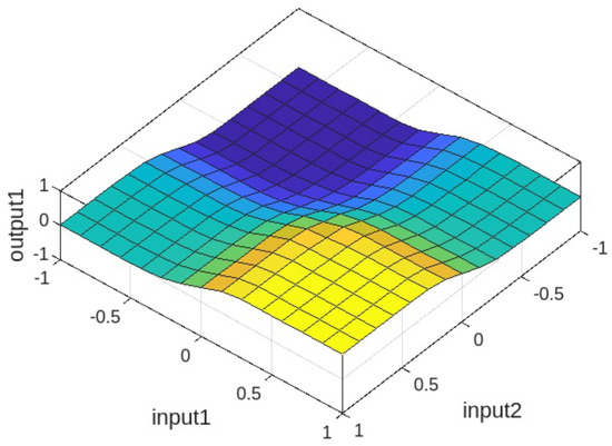
Figure 16.
Working surface of the fuzzy controller (bottom view).
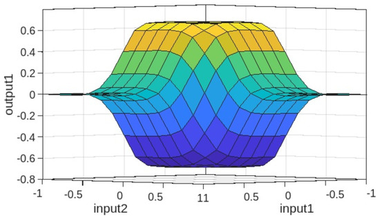
Figure 17.
Working surface of the fuzzy controller (rear view).
4.3. Analysis of Results
4.3.1. DFIG Analysis and Compensator of the Proposed System
In the systems studied, it is evident that when the DFIG generator is installed, the sinusoidal curve of the system is affected by gaps that occur due to several factors, particularly the torsional modes that interact with the generator control. These gaps, being periodic, produce a resonant phenomenon resulting in oscillations and instability in the network, Figure 18.
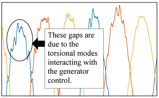
Figure 18.
Dips in IEEE distribution systems.
As mentioned above, the connection of the DFIG alters the system bus conditions, which excite oscillations and affect the system’s stability. Figure 19 and Figure 20 show the systems before and after the implementation of the proposed modules. The system oscillations occur because it is already in a resonance condition, indicating that without an additional controller, the system will not work correctly. Systems with DFIG exhibit wider and more uncontrolled fluctuations around 0.97 p.u. and 1.03 p.u. in the 13-bar system, as well as from 0.98 p.u. to 1 p.u., with a slow response and resonance. On the other hand, with the implementation of the STATCOM module with fuzzy logic and PI control, the system improves stability due to the presence of DFIG generators. Fuzzy logic also helps improve and manage the complexity and nonlinearity of the inverter, which, with the implementation of fuzzy rules, helps protect the generators.
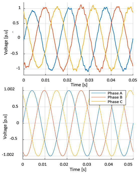
Figure 19.
IEEE13-bus system with and without modules (Bus 2).
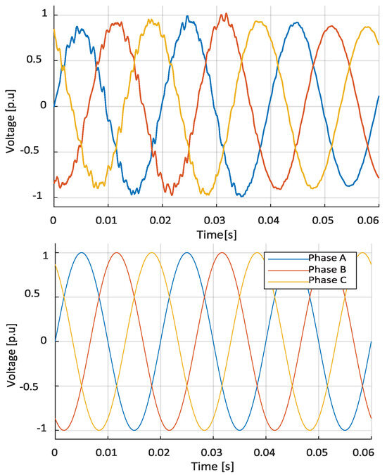
Figure 20.
IEEE 33-bus system with and without modules (Bus 22).
Figure 21 and Figure 22 show how the system stabilizes after the implementation of STATCOM modules with fuzzy logic. As these elements manage the uncertainty and variability of the system parameters, optimizing the response to different operating conditions, such as the incorporation of DFIG, oscillations, and disturbances, is reduced, thus stabilizing the two systems used for the study. The 13-bar system stabilizes at a value of 1.002 p.u., while the 33-bar system stabilizes at 1 p.u. We must protect the generators.
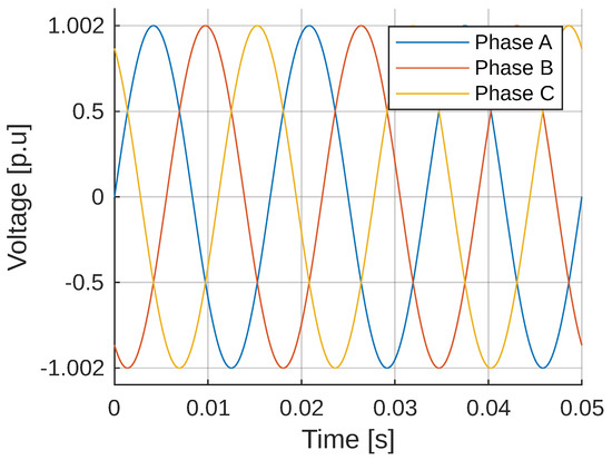
Figure 21.
IEEE 13-bus system with all modules (Bus 2).
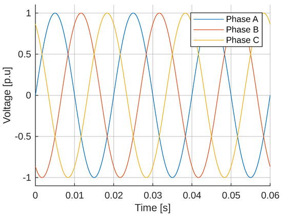
Figure 22.
IEEE 33-bar system with all modules (Bar 22).
4.3.2. Effectiveness of STATCOM Using Fuzzy Logic
The effectiveness of the compensators can be obtained by calculating the mean square error (MSE). This is done between the results of the non-ideal signal 1 (upper part) and the ideal signal 2 (lower part) in Figure 23 and Figure 24, resulting in the implemented compensators having a high effectiveness value close to or equal to 1 (or 100%), which indicates the expected ideal performance represented in the bar charts respectively.
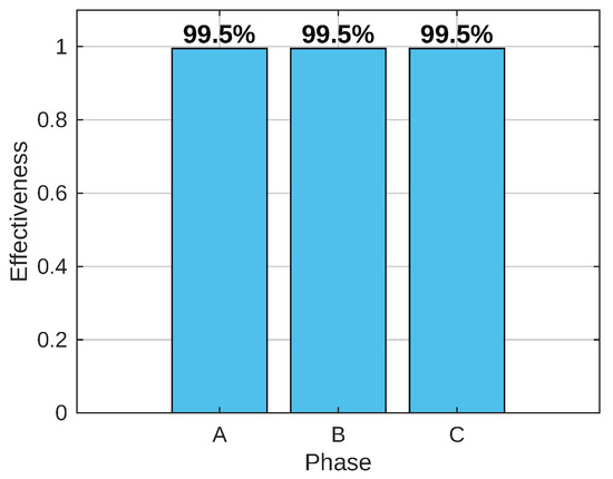
Figure 23.
Effectiveness of the 13-bar compensator system (Bar 2).
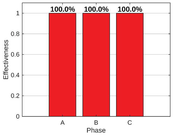
Figure 24.
Effectiveness of the 33-bar compensator system (Bar 22).
Performance of the fuzzy–PI controller. The following Figures have been revised to explicitly show the performance of the proposed fuzzy PI controller in the IEEE test systems. Figure 25a demonstrates that the compensated system converges smoothly to 1 p.u., whereas the uncompensated case exhibits large oscillations. Figure 25b illustrates how the fuzzy–PI controller provides dynamic Q support, stabilizing the system during transients. Figure 25c shows the reduction in oscillatory amplitude when the fuzzy–PI controller is active, indicating improved damping of subsynchronous components. Figure 26 quantifies the improvement: the mean square error of the voltage profile drops from to with fuzzy–PI, reflecting a closer proximity to the reference value of 1 p.u.
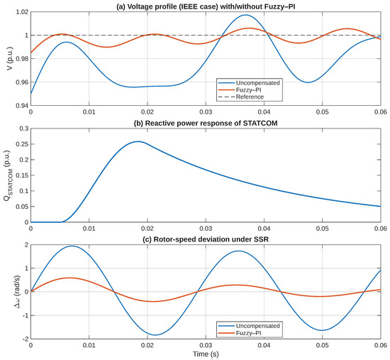
Figure 25.
Integrated performance panel.
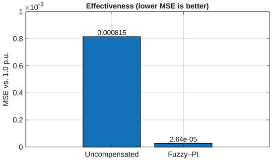
Figure 26.
Effectiveness in terms of MSE.
The successful implementation of subsynchronous resonance (SSR) countermeasures in operational wind farms remains contingent upon the availability of robust and dependable communication and monitoring architectures. Recent progress in the Internet of Things (IoT)-oriented analogue modulation approaches has yielded significant gains in communication efficacy and resiliency across extensive power-generation landscapes. In particular, tailored modulation techniques engineered for the IoT have been introduced to furnish low-latency, high-reliability wireless links specifically within heavy-industrial settings [35]; concurrently, adaptive vehicular IoT communication schemes have been validated for their capacity to scale and maintain performance stability amid rapidly evolving operational environments [36]. Though the present analysis does not encompass these technologies in detail, their deployment provides a substantive auxiliary role to SSR countermeasures by enabling near-continuous, high-fidelity observation and supervisory modulation within geographically dispersed wind-generation fleets.
5. Conclusions
The results show that the implementation of the fuzzy–PI controller improves voltage stability. In addition, subsynchronous oscillations are effectively suppressed, which demonstrates the strength of the proposed control strategy. However, by integrating the STATCOM with fuzzy logic, effective system stabilization was achieved, minimizing the effects of these oscillations and improving the quality and reliability of the power supply with voltage improvement to values equal to or close to 1 per unit.
The identification, characterization, and development of a fuzzy logic-based STATCOM has proven to be an effective solution for mitigating subsynchronous resonance in systems with doubly fed induction generators (DFIGs). In both 13- and 33-bus distribution systems, it was observed that the implementation of the fuzzy logic STATCOM reduced the oscillations and disturbances caused by torsional modes interacting with the DFIG generator control, stabilizing the system.
The fuzzy logic used in the STATCOM enabled adaptive and flexible control in response to variations in the parameters set by the DFIG within the system, resulting in an optimal response to voltage fluctuations and changing operating conditions. This approach enhanced the system’s ability to handle parameter uncertainty and variability, thereby improving the management of the nonlinearity in the DFIG inverter.
The results obtained from the simulations of the 13- and 33-bus case studies with and without the implementation of the compensator show a clear improvement in the stability of the voltage signals. The implementation of the modules allowed the system to stabilize quickly, eliminating harmful oscillations and thus ensuring more controlled behavior.
The rules for fuzzy control based on speed deviation inputs and their derivative ( and ) allowed for an adequate response to system fluctuations. The Gaussian membership functions used provided a more robust and flexible approach to mitigating the effects of subsynchronous resonance.
The implementation of advanced technologies, such as STATCOM using fuzzy logic, is an effective solution for mitigating subsynchronous resonance, thereby contributing to the development of stable and reliable electrical systems.
From an economic viewpoint, the integration of the fuzzy–PI-based STATCOM controller for subsynchronous resonance (SSR) suppression is superior to prevailing countermeasures. Devices featuring series compensation, such as gate-controlled series capacitors (GCSCs) and superconducting fault-current limiters (SFCLs), necessitate large-scale capital outlay as well as intricate integration, thereby inflating both devices’ acquisition and operational costs. Similarly, contemporary intelligent control paradigms, including adaptive neuro-fuzzy inference systems (ANFIS) and variable-structure active disturbance-rejection control (ADRC), impose increased computational overhead and recurring licensing expenses that may deter widespread utilization. Conversely, the fuzzy–PI adaptive controller can be superimposed upon standard STATCOM architecture with, at most, a negligible increment of processing burden. By capitalizing upon the functionality of present STATCOM devices, which are already situated in numerous distribution grids to deliver voltage profile stabilization and reactive-power compensation, the solution in question yields a definitive economic edge. This property is magnified by the fact that the assigned controller encapsulated in a software patch or firmware update incurs orders of magnitude less capital outlay than alternative hardware-centric remedies. In essence, the asserted fuzzy–PI controller not only heightens operational robustness against subsynchronous oscillations but also conveys quantifiable financial merit, foregrounding a dual-benefit scenario that maximizes utilization of extant capital and forestalls recourse to untested expenses and installation interruptions.
Future Work
There are various strategies to mitigate SSSR. In this context, we propose the development of hybrid intelligent control algorithms that integrate fuzzy logic, such as Particle Swarm Optimization (PSO) and Genetic Algorithm (GA), to optimize the real-time performance of STATCOM under SSR conditions. Given the importance of the SSR analysis, this study can be completed by implementing metaheuristic algorithms that automatically determine the optimal location of the STATCOM device in distribution and transmission networks. This article lays the foundations for future technical research aimed at developing a database of SSR events that have occurred in real wind farms, in collaboration with electricity system operators. This database will enable systematic recording of real SSR incidents and facilitate validation of simulation models using data obtained directly from the field.
Author Contributions
L.C. conceptualized the study, analyzed the data, and wrote the initial draft. L.T. analyzed the data, revised the draft, M.J. and C.B.-S. provided critical feedback, and edited the manuscript. All authors have read and agreed to the published version of the manuscript.
Funding
This work was supported by Universidad Politécnica Salesiana and GIREI—Smart Grid Research Group.
Institutional Review Board Statement
Not applicable.
Informed Consent Statement
Informed consent is obtained from all subjects involved in the study.
Data Availability Statement
The original contributions presented in this study are included in the article. Further inquiries can be directed to the corresponding author.
Conflicts of Interest
The authors declare no conflicts of interest.
Abbreviations
The following abbreviations are used in this manuscript:
| STATCOM | Static Synchronous Compensator |
| DFIG | Doubly-Fed Induction Generator |
| FACTS | Flexible AC Transmission Systems |
| SSR | Subsynchronous Resonance |
| FLC | Fuzzy Logic Controller |
| FRT | Fault Ride-Through |
| RSC | Rotor Side Converter |
| GCSC | Gate-Controlled Series Capacitor |
| ADRC | Active Disturbance Rejection Controller |
| ANFIS | Adaptive Neuro-Fuzzy Inference System |
| PID | Proportional-Integral-Derivative Controller |
| PI | Proportional-Integral Controller |
| PMSG | Permanent Magnet Synchronous Generator |
| PSS | Power System Stabilizer |
| SFCL | Superconducting Fault Current Limiter |
| VSI | Voltage Stability Index |
| TPSI | Transient Power Stability Index |
| PAC | Pitch Angle Control |
| MPPT | Maximum Power Point Tracking |
References
- Sun, C.; Chen, J.; Tang, Z. New Energy Wind Power Development Status and Future Trends. In Proceedings of the International Conference on Advanced Electrical Equipment and Reliable Operation, AEERO 2021, Beijing, China, 15–17 October 2021; Institute of Electrical and Electronics Engineers Inc.: Manhattan, NY, USA, 2021. [Google Scholar] [CrossRef]
- Ahmed, S.D.; Al-Ismail, F.S.; Shafiullah, M.; Al-Sulaiman, F.A.; El-Amin, I.M. Grid Integration Challenges of Wind Energy: A Review. IEEE Access 2020, 8, 10857–10878. [Google Scholar] [CrossRef]
- Fuentes-Flores, S.; Vega-Herrera, J.; Cortes-Carmona, M.; Molina-Rotter, J.; Barrientos-Hernandez, J. Modal Analysis for Subsynchronous Resonance Studies in DFIG-Based Wind Power Plants Connected to Compensated Transmission Lines and Weak Systems. In Proceedings of the IEEE CHILEAN Conference on Electrical, Electronics Engineering, Information and Communication Technologies, ChileCon, Valdivia, Chile, 5–7 December 2023; Institute of Electrical and Electronics Engineers Inc.: Manhattan, NY, USA, 2023. [Google Scholar] [CrossRef]
- Li, Z.; Khazaei, J. SSR Mitigation of DFIG Wind Power Plants Using Virtual Synchronous Generator Control. In Proceedings of the 2020 52nd North American Power Symposium, NAPS, Tempe, AZ, USA, 11–13 April 2021; Institute of Electrical and Electronics Engineers Inc.: Manhattan, NY, USA, 2021; Volume 4. [Google Scholar] [CrossRef]
- Verma, N.; Kumar, N.; Gupta, S.; Malik, H.; Márquez, F.P.G. Review of sub-synchronous interaction in wind integrated power systems: Classification, challenges, and mitigation techniques. Prot. Control. Mod. Power Syst. 2023, 8, 17. [Google Scholar] [CrossRef]
- Varela, J.; Parada, M. Simulation and mitigation of subsynchronous resonance in power systems. In Proceedings of the 2021 IEEE International Conference on Automation/24th Congress of the Chilean Association of Automatic Control, ICA-ACCA 2021, Valparaíso, Chile, 22–26 March 2021; Institute of Electrical and Electronics Engineers Inc.: Manhattan, NY, USA, 2021; Volume 3. [Google Scholar] [CrossRef]
- Padmaja, A.; Shanmukh, A.; Mendu, S.S.; Devarapalli, R.; González, J.S.; Márquez, F.P.G. Design of capacitive bridge fault current limiter for low-voltage ride-through capacity enrichment of doubly fed induction generator-based wind farm. Sustainability 2021, 13, 6656. [Google Scholar] [CrossRef]
- Chikohora, T.E.; Oyedokun, D.T. Sub-Synchronous Resonance (SSR) in Series Compensated Networks with High Penetration of Renewable Energy Sources. In Proceedings of the 2020 International SAUPEC/RobMech/PRASA Conference, Cape Town, South Africa, 29–31 January 2020; IEEE: New York, NY, USA, 2020; Volume 1, pp. 1–6. [Google Scholar] [CrossRef]
- Ramya, G.; Suresh, P.; Jayashree, J.; Charles, A.A.; Daniya, T. Review and Analysis of Techniques to Mitigate Sub Synchronous Resonance using FACTS Devices. In Proceedings of the 2022 International Virtual Conference on Power Engineering Computing and Control: Developments in Electric Vehicles and Energy Sector for Sustainable Future, PECCON 2022, Chennai, India, 5–6 May 2022; Institute of Electrical and Electronics Engineers Inc.: Manhattan, NY, USA, 2022. [Google Scholar] [CrossRef]
- Vishwakarma, V.K.; Srivastava, S.; Zeeshan, A.; Maurya, S.K. Mitigation of Subsynchronous Resonance by STATCOM with Fuzzy Logic Controller. In Proceedings of the 2024 3rd International Conference on Power Electronics and IoT Applications in Renewable Energy and its Control, PARC 2024, Mathura, India, 23–24 February 2024; Institute of Electrical and Electronics Engineers Inc.: Manhattan, NY, USA, 2024; pp. 535–539. [Google Scholar] [CrossRef]
- Bostani, Y.; Jalilzadeh, S.; Mobayen, S.; Rojsiraphisal, T.; Bartoszewicz, A. Damping of Subsynchronous Resonance in Utility DFIG-Based Wind Farms Using Wide-Area Fuzzy Control Approach. Energies 2022, 15, 1787. [Google Scholar] [CrossRef]
- Arockiaraj, S.; Manikandan, B.V.; Bhuvanesh, A. Fuzzy Logic Controlled Statcom with a Series Compensated Transmission Line Analysis. Rev. Roum. Sci. Tech.—Sér. Électrotech. Énerg. 2023, 68, 307–312. [Google Scholar] [CrossRef]
- Kumar, I.; Singh, A.; Nandanwar, S.R. Static Synchronous Compensator Using Fuzzy-PI Controller. In Proceedings of the 2024 IEEE 2nd International Conference on Innovations in High Speed Communication and Signal Processing (IHCSP), Bhopal, India, 6–8 December 2024; IEEE: New York, NY, USA, 2024; pp. 1–4. [Google Scholar] [CrossRef]
- Ajami, A.; Taheri, N.; Younesi, M. A Novel Hybrid Fuzzy/LQR Damping Oscillations Controller Using STATCOM. In Proceedings of the 2009 Second International Conference on Computer and Electrical Engineering, Dubai, United Arab Emirates, 28–30 December 2009; IEEE: New York, NY, USA, 2009; pp. 348–352. [Google Scholar] [CrossRef]
- Yousuf, V.; Ahmad, A. Optimal design and application of fuzzy logic equipped control in STATCOM to abate SSR oscillations. Int. J. Circuit Theory Appl. 2021, 49, 4070–4087. [Google Scholar] [CrossRef]
- Kumar, V.; Pandey, A.S.; Sinha, S.K. Stability Improvement of DFIG-Based Wind Farm Integrated Power System Using ANFIS Controlled STATCOM. Energies 2020, 13, 4707. [Google Scholar] [CrossRef]
- Dwijendra, N.K.A.; Jalil, A.T.; Abed, A.M.; Bashar, B.S.; Al-Nussairi, A.K.J.; Hammid, A.T.; Shamel, A.; Uktamov, K.F. Improving the transition capability of the low-voltage wind turbine in the sub-synchronous state using a fuzzy controller. Clean Energy 2022, 6, 682–692. [Google Scholar] [CrossRef]
- Bostani, Y.; Jalilzadeh, S.; Mobayen, S.; Skruch, P.; Fekih, A.; ud Din, S. Damping sub-synchronous resonance in DFIG wind farms: An innovative controller utilizing wide-area measurement systems. Energy Rep. 2023, 10, 333–343. [Google Scholar] [CrossRef]
- Dey, B.; Bhattacharyya, B.; Márquez, F.P.G. A hybrid optimization-based approach to solve environment constrained economic dispatch problem on microgrid system. J. Clean. Prod. 2021, 307, 127196. [Google Scholar] [CrossRef]
- Dey, B.; Raj, S.; Mahapatra, S.; Márquez, F.P.G. Optimal scheduling of distributed energy resources in microgrid systems based on electricity market pricing strategies by a novel hybrid optimization technique. Int. J. Electr. Power Energy Syst. 2022, 134, 107419. [Google Scholar] [CrossRef]
- Xu, Y.; Zhao, S. Mitigation of subsynchronous resonance in series-compensated dfig wind farm using active disturbance rejection control. IEEE Access 2019, 7, 68812–68822. [Google Scholar] [CrossRef]
- Yao, J.; Wang, X.; Li, J.; Liu, R.; Zhang, H. Sub-Synchronous Resonance Damping Control for Series-Compensated DFIG-Based Wind Farm with Improved Particle Swarm Optimization Algorithm. IEEE Trans. Energy Convers. 2019, 34, 849–859. [Google Scholar] [CrossRef]
- Li, Q.; Hu, Y.; Wang, Y.; Zhou, C.; Li, Y.; Han, J. Design and Simulation of a Novel Subsynchronous Control Interaction Damping Controller. In Proceedings of the 2020 Asia Energy and Electrical Engineering Symposium (AEEES), Chengdu, China, 29–31 May 2020; IEEE: New York, NY, USA, 2020; Volume 5, pp. 391–395. [Google Scholar] [CrossRef]
- Valikhani, M.; Wu, T.; Schafer, U. Dynamic Modelling and Control of Multiphase Doubly Fed Induction Generator in Wind Turbine Systems. In Proceedings of the 2020 International Symposium on Power Electronics, Electrical Drives, Automation and Motion (SPEEDAM), Sorrento, Italy, 24–26 June 2020; IEEE: New York, NY, USA, 2020; Volume 6, pp. 774–778. [Google Scholar] [CrossRef]
- Penrose, H.W. Evaluation of DFIG Wind Turbine Generator and Transformer Conditions with Electrical Signature Analysis. In Proceedings of the 2022 IEEE Electrical Insulation Conference, EIC 2022, Knoxville, TN, USA, 19–23 June 2022; Institute of Electrical and Electronics Engineers Inc.: Manhattan, NY, USA, 2022; pp. 379–384. [Google Scholar] [CrossRef]
- Toledo, E.J.; Aromataris, L.; Tarnowski, G.C.; Perrone, O.E. Modelo de aerogenerador de velocidad variable DFIG con control LVRT. In Proceedings of the 2014 IEEE Biennial Congress of Argentina, ARGENCON 2014, Bariloche, Argentina, 11–13 June 2014; IEEE Computer Society: Los Alamitos, CA, USA, 2014; pp. 696–701. [Google Scholar] [CrossRef]
- Li, N.; Wang, L.; Yang, H.; Ma, H. Stability Analysis for SSR of DFIG-Based Wind Farm Considering STATCOM Capacity Constraint. In Proceedings of the 2019 22nd International Conference on Electrical Machines and Systems (ICEMS), Harbin, China, 11–14 August 2019; IEEE: New York, NY, USA, 2019; Volume 8, pp. 1–6. [Google Scholar] [CrossRef]
- Alcarruz, B.; Fuentes, C.; Chavez, H.; Riquelme, E. Sub-Synchronous Resonance Study for Future Scenarios in the Chilean Power System. In Proceedings of the 2024 IEEE International Conference on Automation/XXVI Congress of the Chilean Association of Automatic Control (ICA-ACCA), Santiago, Chile, 20–23 October 2024; IEEE: New York, NY, USA, 2024; Volume 10, pp. 1–6. [Google Scholar] [CrossRef]
- Wu, K.; Meng, Y.; Pan, X.; Zou, Y.; Ye, R.; Xue, J. A Combined SSR Damping Strategy Based on Virtual Resistance Method and SSR Damping Controller in DFIG-Based Wind Farm. In Proceedings of the 2019 IEEE 8th International Conference on Advanced Power System Automation and Protection (APAP), Xi’an, China, 21–24 October 2019; IEEE: New York, NY, USA, 2019; Volume 10, pp. 1451–1455. [Google Scholar] [CrossRef]
- Karunanayake, C.; Ravishankar, J.; Dong, Z.Y. Nonlinear SSR Damping Controller for DFIG Based Wind Generators Interfaced to Series Compensated Transmission Systems. IEEE Trans. Power Syst. 2020, 35, 1156–1165. [Google Scholar] [CrossRef]
- Jewel, A.S.; Roy, T.K. Design of Double-Integral Sliding Mode Controllers to Mitigate SSR Problems in DFIG-Based Wind Farms Using Fast Power Reaching Laws. In Proceedings of the ICDRET 2021—6th International Conference on Development in Renewable Energy Technology, Dhaka, Bangladesh, 28–30 December 2021; Institute of Electrical and Electronics Engineers Inc.: Manhattan, NY, USA, 2021. [Google Scholar] [CrossRef]
- Bharat, M.; Ch, S.; Dash, R.; Swain, D.M. Asymmetrical Fault Analysis Using P2P Coordinated Control System for DFIG-STATCOM. In Proceedings of the 2023 1st International Conference on Circuits, Power, and Intelligent Systems, CCPIS 2023, Bhubaneswar, India, 1–3 September 2023; Institute of Electrical and Electronics Engineers Inc.: Manhattan, NY, USA, 2023. [Google Scholar] [CrossRef]
- Ivanova, M.S. Fuzzy Set Theory and Fuzzy Logic for Activities Automation in Engineering Education. In Proceedings of the 2019 IEEE XXVIII International Scientific Conference Electronics (ET), Sozopol, Bulgaria, 12–14 September 2019; IEEE: New York, NY, USA, 2019; Volume 9, pp. 1–4. [Google Scholar] [CrossRef]
- Toumi, I.D.; Meghni, B.T. Monitoring of Wind Energy Conversion System by on Dimensional Adaptive Tuning Fuzzy Logic Controller. In Proceedings of the 2022 5a Conferencia Internacional Sobre Sistemas Avanzados y Tecnologías Emergentes (IC-ASET), Hammamet, Tunisia, 22–25 March 2022; pp. 491–499. [Google Scholar] [CrossRef]
- Luo, J.; Bai, Y.; Bai, B.; Chen, C.; Wen, W. A Multi-layer Superposition Modulation Scheme to Improve the Data Rate for IoT Communications. In Proceedings of the 2023 IEEE/CIC International Conference on Communications in China (ICCC Workshops), Dalian, China, 10–12 August 2023; pp. 1–6. [Google Scholar] [CrossRef]
- Ma, H.; Tao, Y.; Fang, Y.; Chen, P.; Li, Y. Multi-Carrier Initial-Condition-Index-aided DCSK Scheme: An Efficient Solution for Multipath Fading Channel. IEEE Trans. Veh. Technol. 2025, 1–14. [Google Scholar] [CrossRef]


Disclaimer/Publisher’s Note: The statements, opinions and data contained in all publications are solely those of the individual author(s) and contributor(s) and not of MDPI and/or the editor(s). MDPI and/or the editor(s) disclaim responsibility for any injury to people or property resulting from any ideas, methods, instructions or products referred to in the content. |
© 2025 by the authors. Licensee MDPI, Basel, Switzerland. This article is an open access article distributed under the terms and conditions of the Creative Commons Attribution (CC BY) license (https://creativecommons.org/licenses/by/4.0/).