
Design and Analysis of a Bearing-Integrated Rotary Transformer


Abstract
1. Introduction
2. Characteristic Analysis of Bearing-Integrated Rotary Transformer
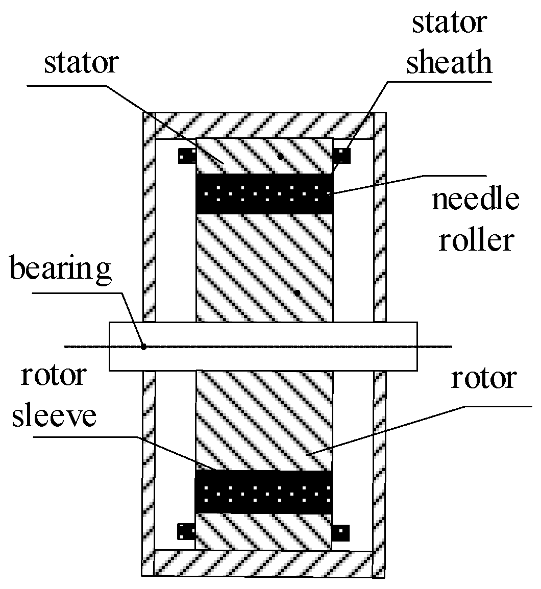
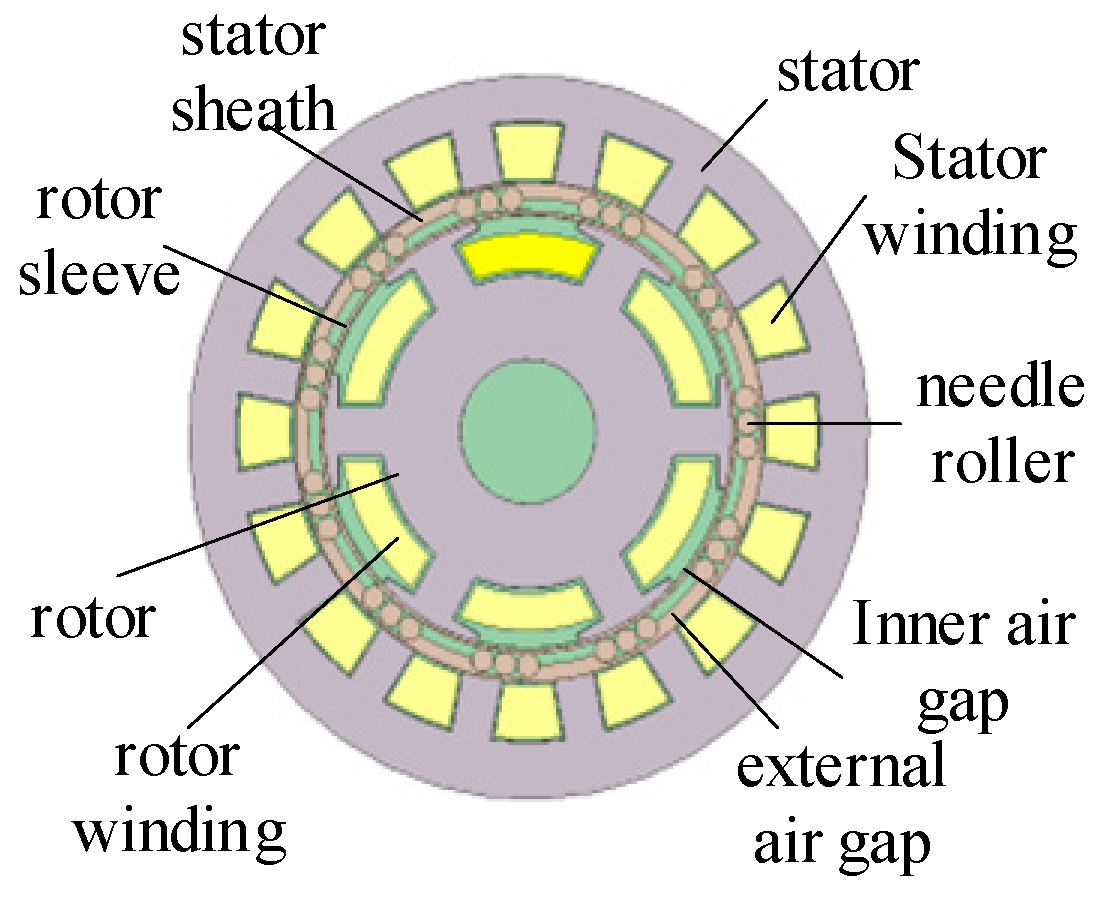
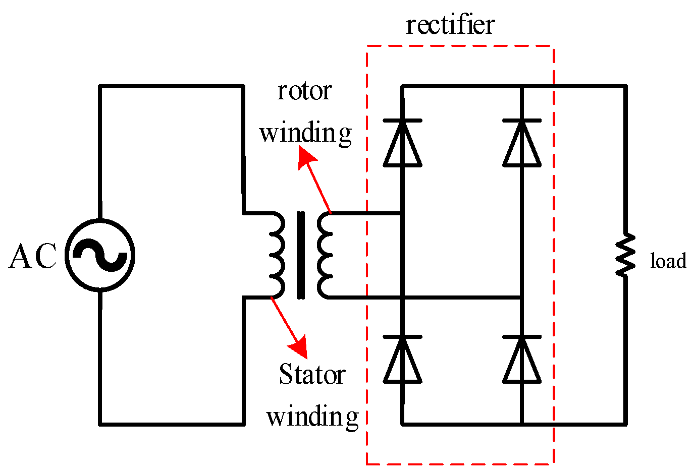
2.1. The Basic Structure and Excitation Principle of a Bearing-Integrated Rotary Transformer
2.2. Equivalent Magnetic Circuit Model
2.3. Equivalent Circuit Model
3. The Design of a Bearing-Integrated Rotary Transformer
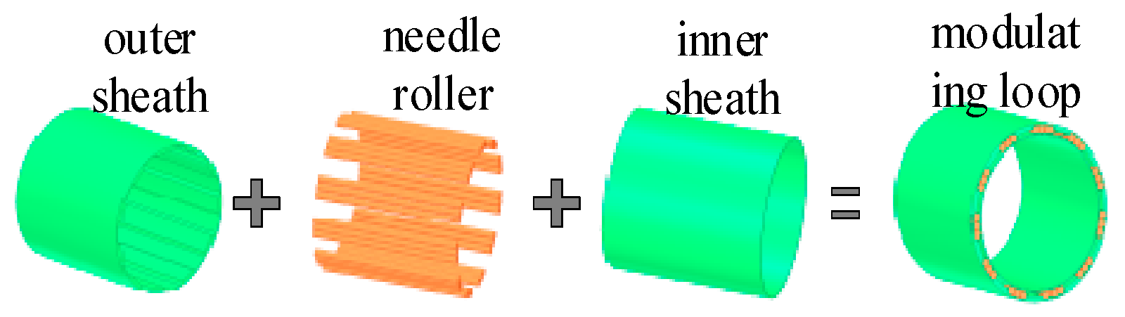
3.1. Machinery Design
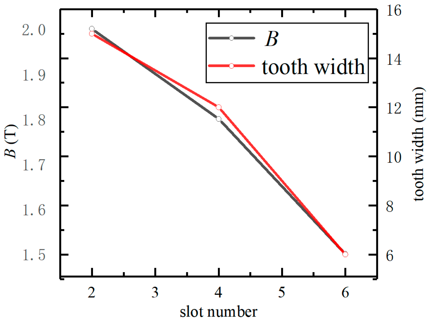
3.2. Stator Structure Design
3.3. Winding Design
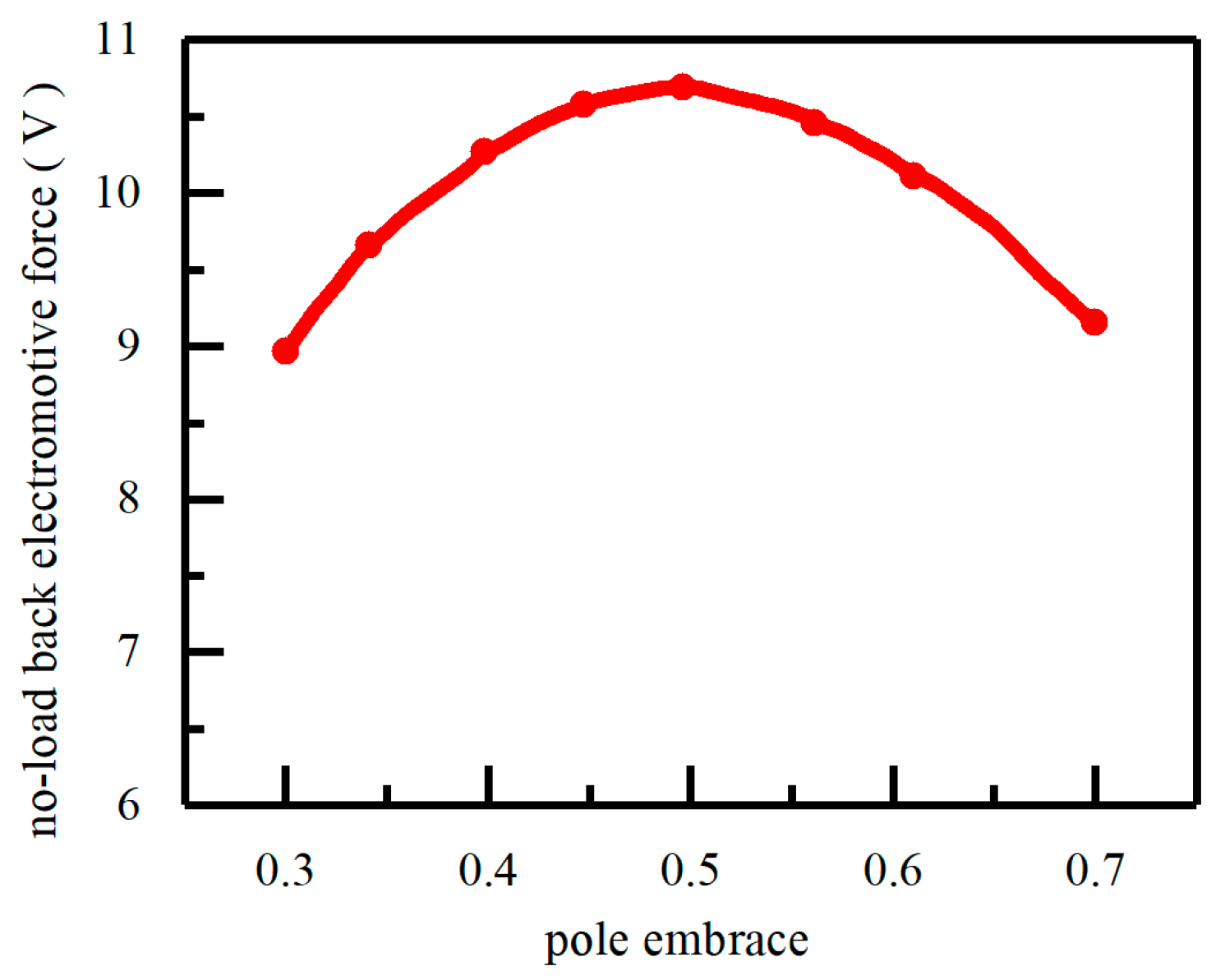
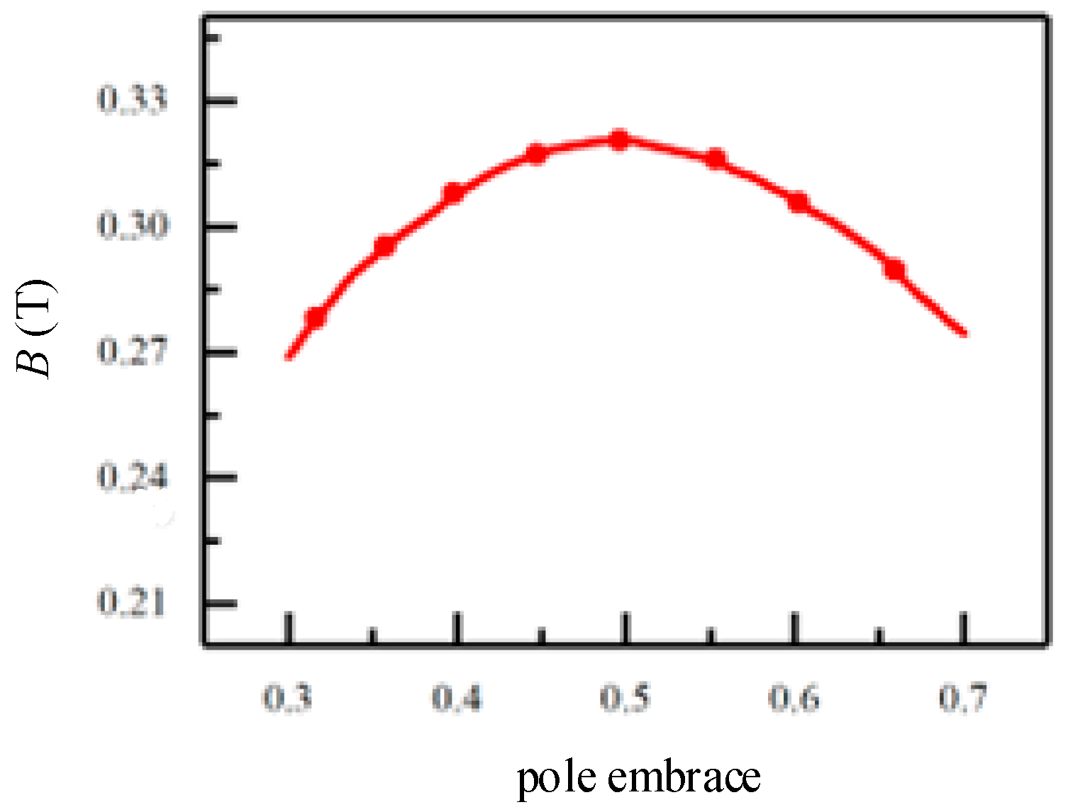
3.4. Analysis of Polar Arc Coefficient Selection
4. Simulation Analysis of Bearing-Integrated Rotary Transformer
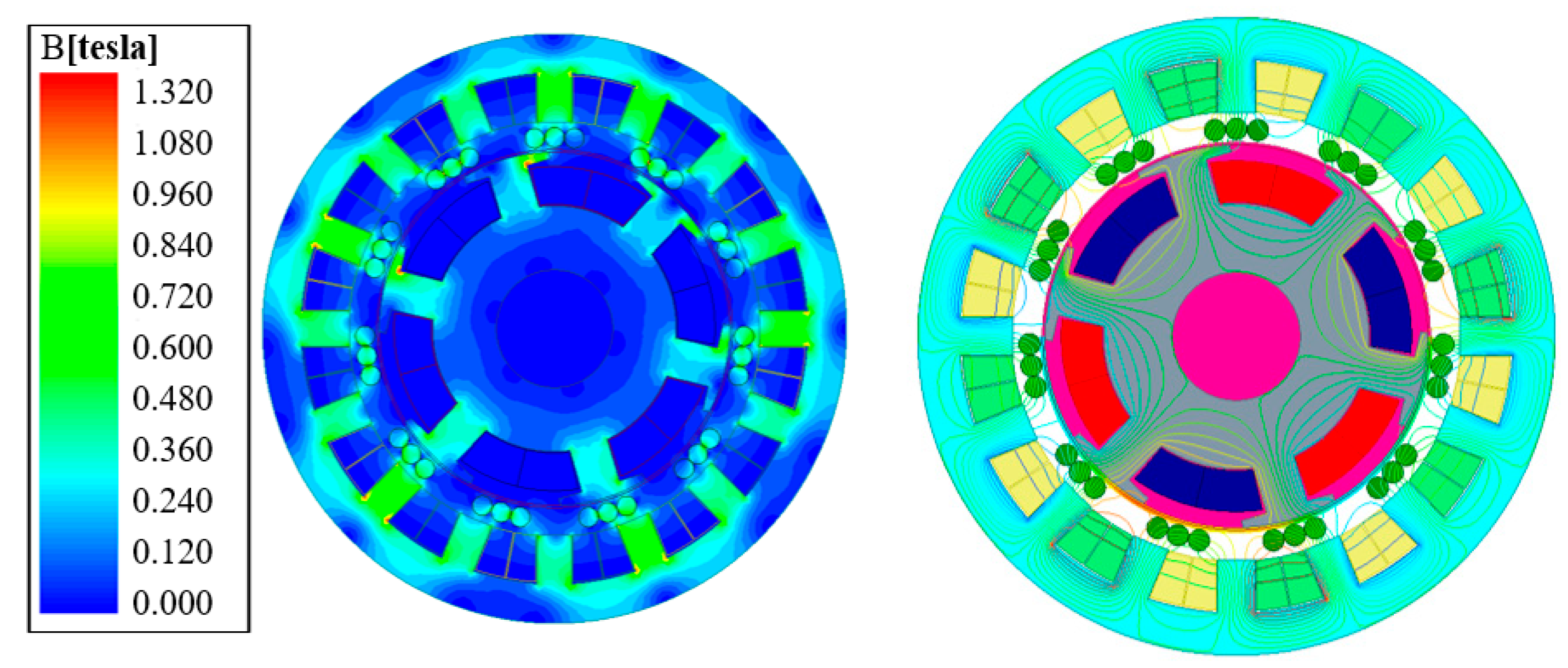
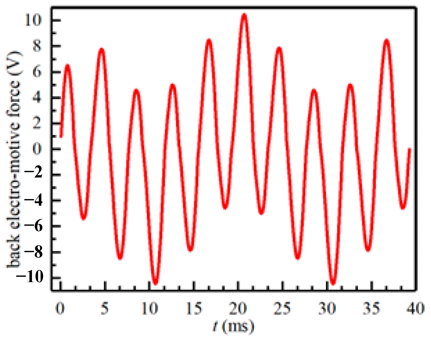
4.1. Electromagnetic Simulation
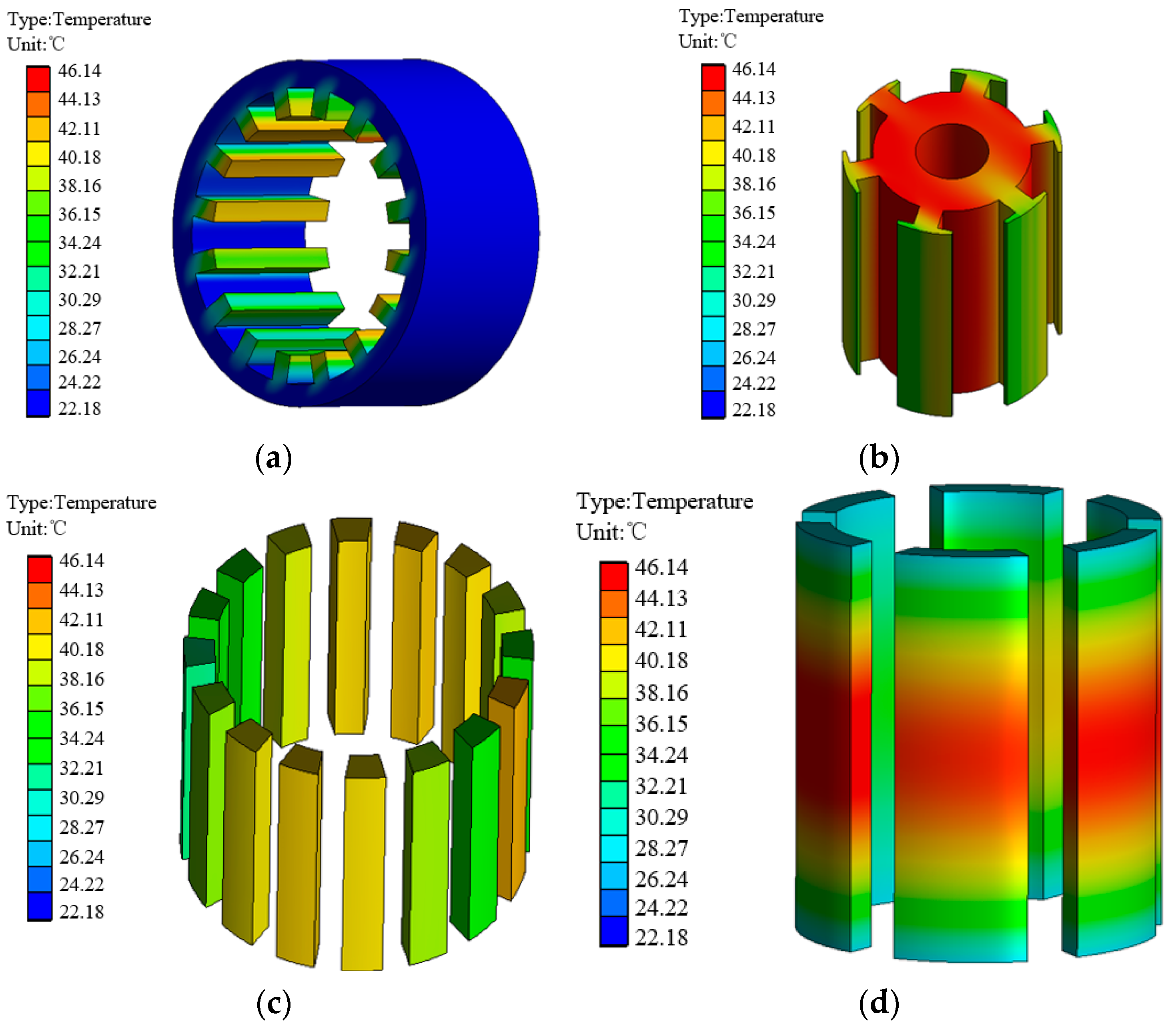
4.2. Temperature Field Simulation
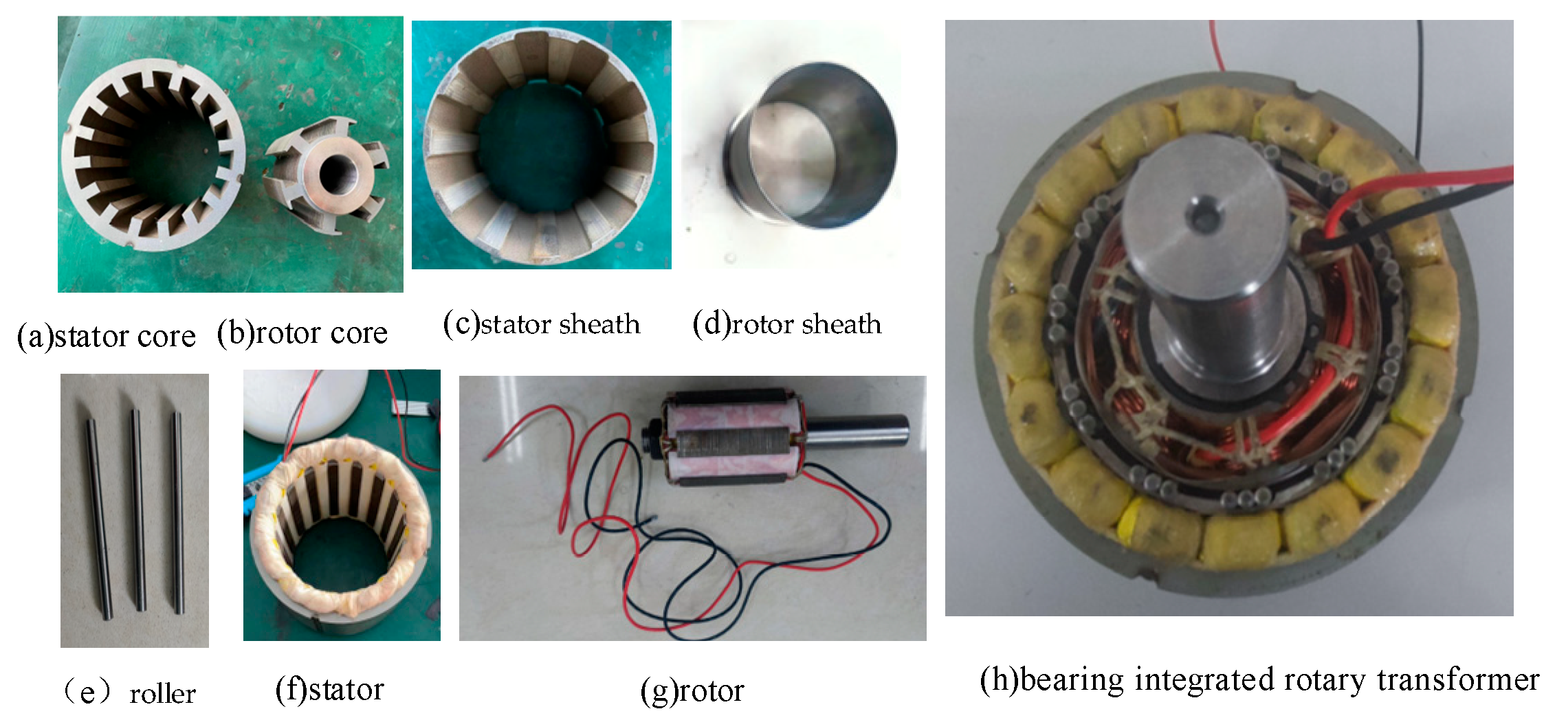
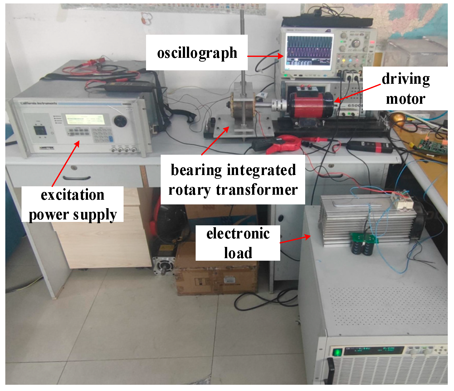
5. Prototype Development and Experimental Analysis of Bearing-Integrated Rotary Transformer
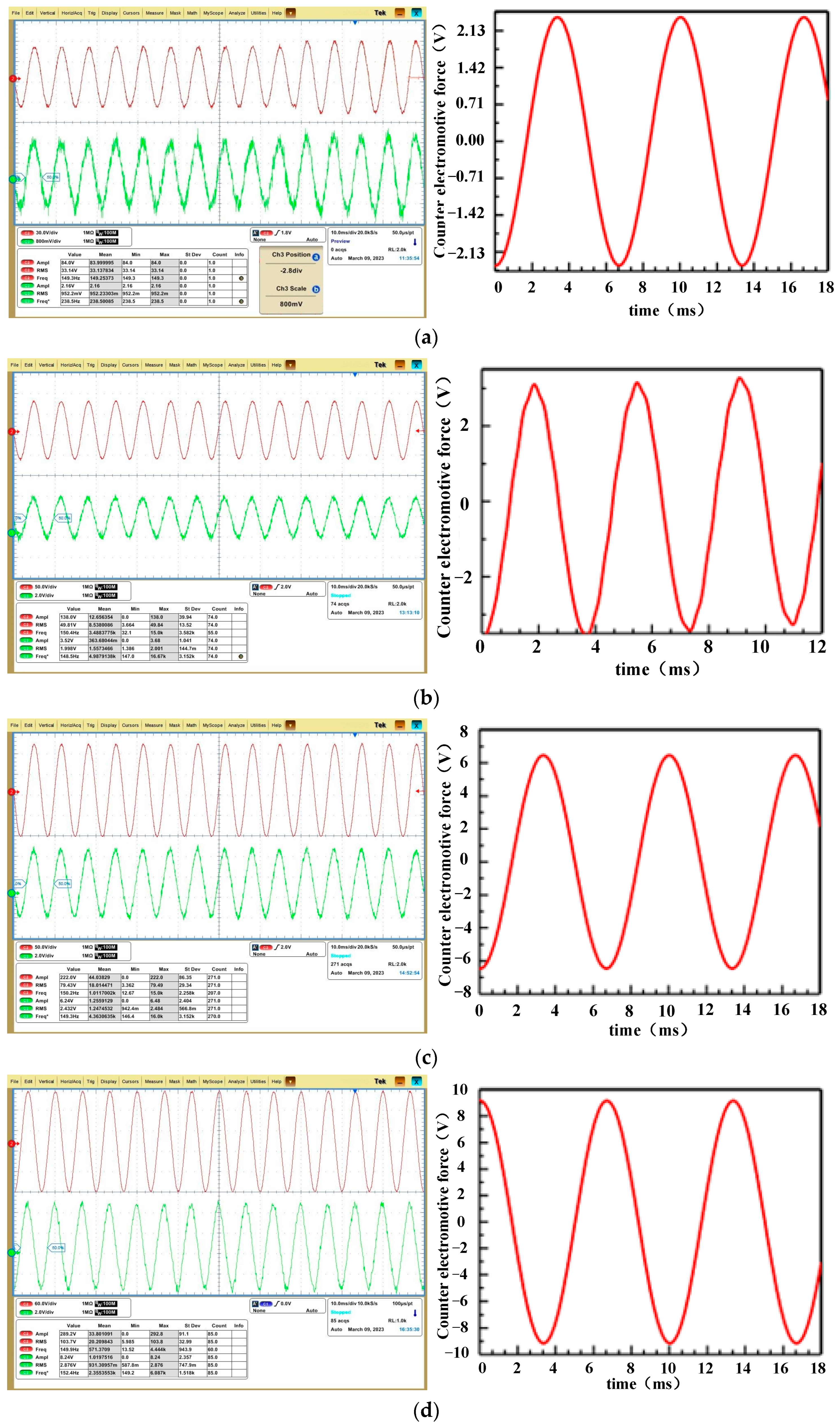
5.1. No-Load Test
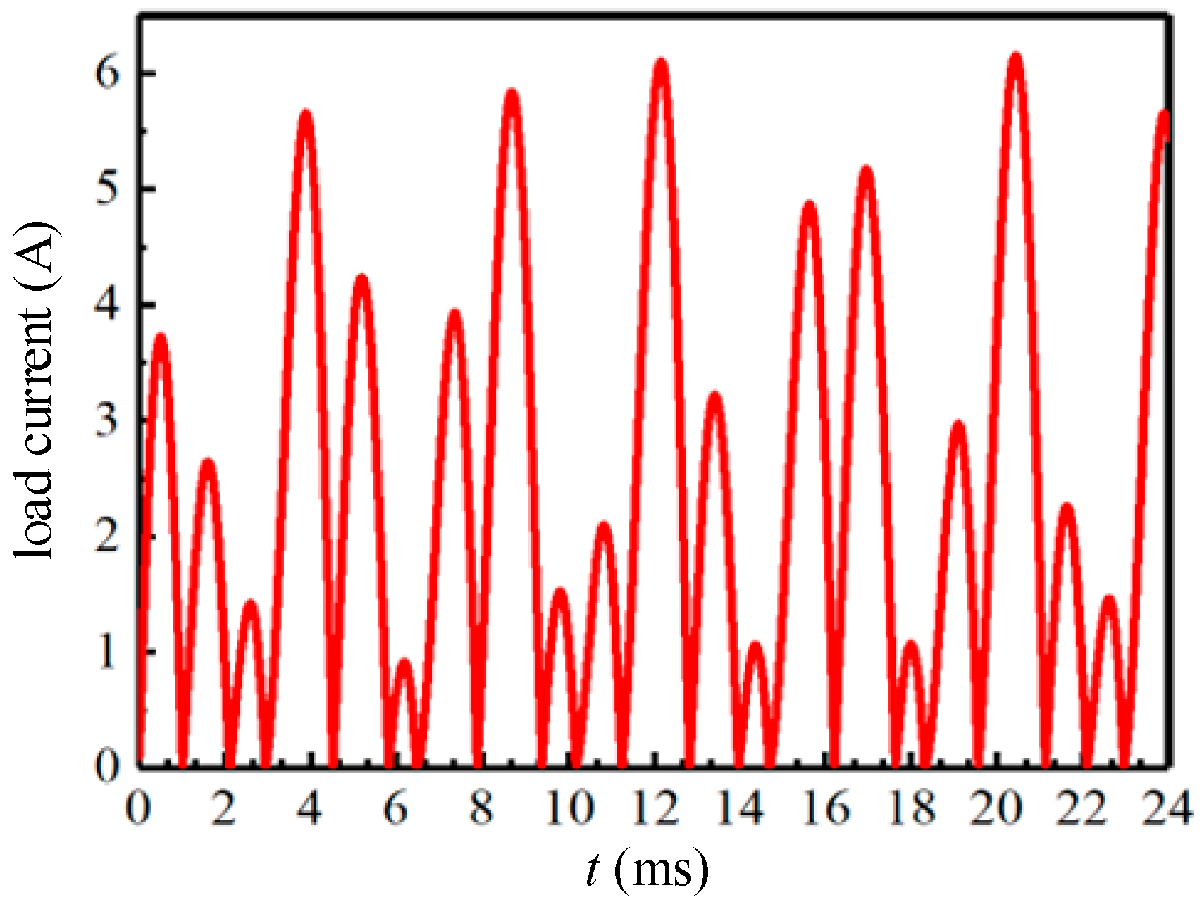
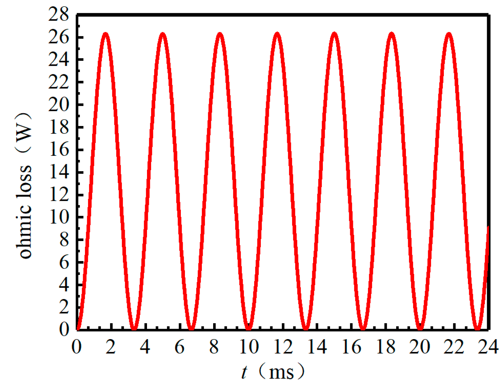
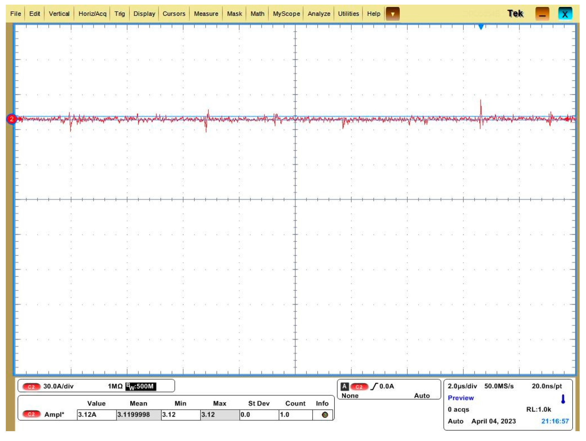
5.2. Load Test
5.3. Simulation and Experimental Results
6. Conclusions
Author Contributions
Funding
Data Availability Statement
Conflicts of Interest
Glossary
| ps | The pole pairs of the stator air gap magnetic field |
| p0 | The number of needle rollers in the modulation ring |
| pr | The pole pairs of the rotor air gap magnetic field |
| ns | The stator air gap magnetic field speed |
| nr. | The rotor speed |
| I1 | Sinusoidal excitation current |
| The fundamental pulsating magnetomotive force | |
| Fpm | The amplitude of the fundamental magnetomotive force |
| ωp | The angular frequency |
| Kd1 | Winding coefficient |
| Nc | Number of windings |
| q | Number of coils |
| t | Time |
| Mechanical angle | |
| Nr | The number of teeth in the rotor |
| K | Magnetic pole arc coefficient |
| h | Air gap height |
| The air gap permeability per unit area | |
| The air gap permeability fundamental component | |
| The order permeability harmonic amplitude | |
| The angle between the rotor and the synthetic magnetomotive force axis | |
| ωrm | The rotor speed |
| Stator impedance | |
| Rotor reactance | |
| Rotor leakage reactance | |
| The vacuum permeability | |
| B | The magnetic flux density |
| f1 | Frequency |
| E2 | The rotor winding is cut to generate the induced potential |
| Es1 | The forward magnetic field cuts the rotor windings to create an induced potential |
| Es2 | The reverse magnetic field cuts the rotor windings to create an induced potential |
| Xm | Excitation reactance |
| P0 | Output power |
| fs | Rated frequency |
| h | Axial length |
| Φs1 | Stator outer diameter |
| Φs2 | Bore diameter |
| Zs | The number of stator slots |
| Ps | Stator pole pairs |
| N1 | Stator winding circles |
| ds | Stator sheath thickness |
| R0 | Rolling needle radius |
| P0 | Modulation ring pole number |
| N0 | The number of rolling needles |
| dr | Rotor sheath thickness |
| Φr1 | Rotor outer diameter |
| Φr2 | Rotor inner diameter |
| Zr | Rotor slot number |
| Pr | Rotor pole pairs |
| N2 | Rotor winding turns |
References
- Zhu, S.; Jiang, B.; Liu, C.; Wang, K.; Zhou, Z.; Yu, J. Research on excitation principle and voltage regulation performance of induction rectifier brushless synchronous motor. Chin. J. Electr. Eng. 2020, 40, 5682–5690. (In Chinese) [Google Scholar]
- Su, Z. Research on Excitation System of Electrically Excited Synchronous Motor Based on Resolver. Master’s Thesis, Shenyang University of Technology, Shenyang, China, 2021. (In Chinese). [Google Scholar]
- Geng, W.; Zhang, Z.; Yu, L.; Yan, Y. Structure principle and magnetic field regulation characteristics of novel parallel hybrid excitation brushless DC motor. J. Electr. Technol. 2013, 28, 131–137+154. (In Chinese) [Google Scholar]
- Dong, J.; Huang, Y.; Jin, L.; Lin, H. Review of Design and Analysis Techniques for High Speed Permanent Magnet Motors. Chin. J. Electr. Eng. 2014, 34, 4640–4653. (In Chinese) [Google Scholar]
- Chan, T.F.; Yan, L.T. Performance analysis of a brushless and exciterless AC generator. IEEE Trans. Energy Convers. 1997, 12, 32–37. [Google Scholar] [CrossRef]
- Jing, L.; Gao, Q.; Wang, C.; Luo, Z.; Xie, L.; Hu, K. Optimization design and characteristic analysis of dual-rotor hybrid excitation motor. J. Mot. Control. 2019, 23, 43–50. (In Chinese) [Google Scholar]
- Shen, Y. Basic Research on a Novel Brushless Hybrid Excitation Synchronous Generator. Master’s Thesis, Shandong University, Jinan, China, 2018. (In Chinese). [Google Scholar]
- Zhen, W. Design and Finite Element Analysis of Electrically Excited Brushless Synchronous Motor. Master’s Thesis, China University of Mining and Technology, Xuzhou, China, 2014. (In Chinese). [Google Scholar]
- Mizuno, T.; Nagayama, K.; Ashikaga, T.; Kobayashi, T. Basic principles and characteristics of hybrid excitation synchronous machine. Electr. Eng. Jpn. 2010, 117, 110–123. [Google Scholar] [CrossRef]
- Aydin, M.; Huang, S.; Lipo, T.A. A new axial flux surface mounted permanent magnet machine capable of field control. In Proceedings of the Conference Record of the 2002 IEEE Industry Applications Conference. 37th IAS Annual Meeting, Pittsburgh, PA, USA, 13–18 October 2002. [Google Scholar]


| Scheme | 12/9 | 14/10 | 16/11 | 18/12 | 20/13 |
|---|---|---|---|---|---|
| back- electromotive force | 13 V | 6.3 V | 11 V | 7.6 V | 8.3 V |
| Parameter | Sign | VAL |
|---|---|---|
| Output power (W) | P0 | 60 |
| Reactive power | Qr | 10.82 |
| Rated frequency (Hz) | fs | 150 |
| Axial length (mm) | h | 80 |
| Stator outer diameter (mm) | Φs1 | 120 |
| Bore diameter (mm) | Φs2 | 84 |
| Number of stator slots | Zs | 16 |
| Stator pole pairs | Ps | 8 |
| Stator winding circles | N1 | 35 |
| Stator sheath thickness (mm) | ds | 1 |
| Rolling needle radius (mm) | R0 | 2 |
| Modulation ring pole number | P0 | 11 |
| Number of rolling needles (a) | N0 | 33 |
| Rotor sheath thickness (mm) | dr | 1 |
| Rotor outer diameter (mm) | Φr1 | 72 |
| Rotor inner diameter (mm) | Φr2 | 24 |
| Rotor slot number | Zr | 6 |
| Rotor pole pairs | Pr | 3 |
| Rotor winding turns | N2 | 15 |
Disclaimer/Publisher’s Note: The statements, opinions and data contained in all publications are solely those of the individual author(s) and contributor(s) and not of MDPI and/or the editor(s). MDPI and/or the editor(s) disclaim responsibility for any injury to people or property resulting from any ideas, methods, instructions or products referred to in the content. |
© 2025 by the authors. Licensee MDPI, Basel, Switzerland. This article is an open access article distributed under the terms and conditions of the Creative Commons Attribution (CC BY) license (https://creativecommons.org/licenses/by/4.0/).
Share and Cite
Fan, X.; Ma, S.; Chen, D.; Liu, C. Design and Analysis of a Bearing-Integrated Rotary Transformer. Energies 2025, 18, 3991. https://doi.org/10.3390/en18153991
Fan X, Ma S, Chen D, Liu C. Design and Analysis of a Bearing-Integrated Rotary Transformer. Energies. 2025; 18(15):3991. https://doi.org/10.3390/en18153991
Chicago/Turabian StyleFan, Xiaoou, Shaohua Ma, Dezhi Chen, and Chaoqun Liu. 2025. "Design and Analysis of a Bearing-Integrated Rotary Transformer" Energies 18, no. 15: 3991. https://doi.org/10.3390/en18153991
APA StyleFan, X., Ma, S., Chen, D., & Liu, C. (2025). Design and Analysis of a Bearing-Integrated Rotary Transformer. Energies, 18(15), 3991. https://doi.org/10.3390/en18153991