Abstract
The stretch film production is highly energy intensive. The components of the technological line are powered by electrical energy, and the heat is used to change the physical state of the raw material (granules). The raw material is poured into FCR (the first calender roller). To solidify the liquid raw material, the calendar must be cooled. The low-temperature heat, treated as waste heat, has dissipated in the atmosphere. Technological innovations were proposed: (a) the raw material comprises raw material (primary) and up to 80% recyclate (waste originating mainly from agriculture), (b) the use of low-temperature waste heat (the cooling of FCR in the process of foil stretch production). A heat recovery line based on two compressor heat pumps (HP, hydraulically coupled) was designed. The waste heat (by low-temperature HP) was transformed into high-temperature heat (by high-temperature HP) and used to prepare the raw material. The proposed technological line enables the management of difficult-to-manage post-production waste (i.e., agriculture and other economic sectors). It reduces energy consumption and raw materials from non-renewable sources (CO2 and other greenhouse gas emissions are reducing). It implements a closed-loop economy based on renewable energy sources (according to the European Green Deal).
1. Introduction
The trend of limiting the use of artificial polymeric materials (packaging, disposable products) makes it necessary to change their production, distribution, use, and recovery or disposal [1,2]. Some products are no longer produced, and others have been replaced or will be replaced by natural, biodegradable, compostable materials [3,4]. However, these activities are not yet fully satisfactory. The technologies being created are not widely commercialized [5]. More often, reusable products (e.g., returnable bottles) and those modified for easy recycling are used [6].
Polymer materials are currently primarily subject to energy recycling, which involves recovering energy from them by burning them or processing them into fuels (solid, liquid, gaseous) [7], e.g., petrol from PET (polyethylene terephthalate) [8]. Few polymer materials are currently subject to material recycling (reuse of waste for producing new materials) [9]. To improve the efficiency of recycling/upcycling, new technologies are being developed, such as thermomechanical processing, chemical recycling (glycolysis, pyrolysis), and biological depolymerization (catalysts, enzymes, microorganisms) [10,11,12,13].
Considering the reduction in greenhouse gas emissions (including CO2) and the promotion of a circular economy (which is the aim of the EU Energy Policy [14]), attention was drawn to the potential of reusing polymer waste in the production of stretch films.
The most commonly used technological process of producing stretch film using the cast method consists of the following operations [15,16]: extrusion (raw material granulate (most often LDPE - low density polyethylene) is heated in extruder (single- or multi-screw extruder) to a liquid state (above the pour point), homogenized and degassed), casting (the material is evenly poured onto a rotating metal drum (cooled), on which it solidifies (while still remaining in a viscous liquid state (above the softening temperature and below the glass transition point)), calendering (the material (already in the form of a film) changes from a viscous liquid state to a viscous elastic state and obtains the intended thickness and strength parameters (several times it is wound through successive calender rolls of different diameters and different rotational speeds)), winding (the finished film ribbon is initially (or finally) wound onto transport or commercial rolls). The process in question is continuous and is sometimes supplemented by operations of initial preparation of the raw material (usually drying), final and/or inter-operational control, cutting, packaging, and storage. The raw material used is in the form of fresh granulate (from primary polymerization) of the material or with the addition of recycled material (up to 20% of the volume [17]), which ensures production stability and repeatability of the finished product (the material is characterized by a stable (statistically) molar mass of the molecules of the polymer constituting it).
The stable temperature of the first calender roller (FCR; where the liquid raw material is fed) guarantees the correct operation of the technological line to produce a stretch film. The FCR acts as a cooler, where the heat it receives is dispersed in the environment (previously treated as waste heat). However, its standardization is necessary in the case of using a non-homogeneous raw material (with the addition of a fraction of recycled material, which may come from different sources). In connection with this, there is a problem of processing recycled material (e.g., removing moisture), where the heat source may be waste technological heat. The use of renewable energy is currently significant, taking into account, among other things, global warming [18,19].
Currently, heat pumps (HP) are an alternative to heating devices using fossil fuels in commercial buildings [20,21] or industry [22], and are also progressively more used in waste heat recovery systems [23,24,25]. Heat pumps use refrigerants, and the traditional (hydrofluorocarbons-HFCs), characterized by high GWP and ODP (global warming potential and ozone depletion potential, respectively), are currently being replaced by environmentally friendly ones [26,27,28].
The work aimed to develop an energy-saving technology for stretch film production. The technology uses a raw material that is a mixture of regranulate (up to 80% of the volume) and base material, as well as process heat (previously treated as waste heat), using compressor HPs. The simulations with developed low- and high-temperature HP with selected ecological refrigerants will enable the analysis of mass flow of the refrigerant, cooling and heating power, electrical energy consumed by the compressor (consequently the COP coefficient), heat exchange rate in evaporator and condenser, and the required flow of the working medium-heat carrier of the technological heat recovery line.
2. Materials and Methods
Developing an energy-saving technological line for producing stretch film (using the recovery of technological heat) requires solving some partial problems.
2.1. Raw Material (Mixture of Regranulate (Up to 80% by Volume) and Base Material)
The problem of recycling plastic waste is its selection (products often consist of several types of plastics (components)), and the material produced from recyclates often has worse properties than produced from base material [29]. Therefore, the raw material used must be characterized by parameters that do not differ significantly (repeatability of production effects).
Demay and Agassant [30] indicate that the available solutions in technological lines for the production of cast stretch films cannot be adapted to the continuous regulation of the process (widely variable production parameters of the raw material).
The proposed solution to obtain stretch film with repeatable properties relies on mixing raw material from different sources (suppliers). However, this requires supplementing the technological line with silo mixers, dosing the raw material to regranulate extruders.
Another problem with using recyclate in film production is its unpleasant smell. The refresher (odour freshener) in the production line was used. Its purpose is to neutralize/remove any volatile substances that may cause unpleasant odours and pose a threat to humans and the environment. This device was integrated into the technological process between the operation of producing regranulate from waste material and the main operation of film casting. The most important element of the refresher is the absorbent beds. Their chemical composition and structure are the supplier’s trade secrets and cannot be disclosed in this report.
2.2. Heat Recovery Line
2.2.1. Refrigerants
The design solution of the cooling system enabling the increase in the temperature level of technological heat depends on the technical parameters of the refrigerant-the saturation temperature (Ts) of the refrigerant (depends on saturation pressure ps) and the critical point (the critical point temperature (Tk) should be higher than the required upper source temperature). The following temperatures of the upper heat source of the heat pump were assumed (technological considerations of the heat recovery line): 95 °C (high temperature HP, [31]) and 35 °C (low temperature HP). Due to the required lower source temperature (15 °C—the FCR), Ts should oscillate within the range of 0–10 °C at a pressure not lower than 1.5 Bar. When selecting refrigerants, the EU Directive [32] was taken into account. The selected refrigerants must have a GWP coefficient of <150 [33,34].
In the present work, the refrigerants should meet the following criteria:
- GWP < 150,
- the critical point pressure < 40 Bar,
- the critical point temperature > 95 °C,
- the saturation pressure > 2 Bar.
Refrigerant Slider (https://reftools.danfoss.com/spa/tools/ref-slider, accessed on 20 June 2025) was used to obtain refrigerant parameters.
2.2.2. Refrigeration Systems
The compressor is also a limitation of the HP refrigeration system, the scope of which must guarantee the scope of temperature changes in the heat source (the lower and upper). The technical parameters of the compressor largely determine the refrigeration efficiency of the HP and the possibility of working in tandem. Additionally, the design of the compressor determines its resistance to operating temperature, flooding (liquid agent) and the possibility of the oil changing (device life).
Four possible refrigeration system designs were considered in this work (Figure 1): a single-stage system, two single-stage systems hydraulically coupled, a two-stage system and a cascade system.
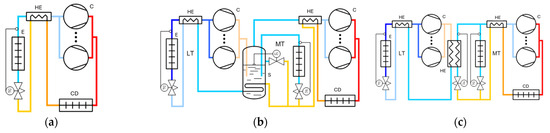
Figure 1.
Refrigeration systems: (a) single-stage, (b) two-stage, (c) cascade; C—compressor, CD—condenser, E—evaporator, HE—heat exchanger, LT—low temperature stage, MT—medium temperature stage, LC—valve controller (level), TC—valve controller (temperature), S—separator of liquid  refrigerant, —low
  temperature, —high temperature (Pack Calculation Pro software, version: v5.5.6).
refrigerant, —low temperature, —high temperature (Pack Calculation Pro software, version: v5.5.6).
2.3. Calculations
The Bitzer software [35] and the Matlab and Simulink Thermolib package were used in this work.
The mass flow rate of the refrigerant (M, kg/s) was calculated as the ratio of the compressor volumetric flow (V, m3/s) and the specific steam volume (v, m3/kg; suction nozzle, temperatures from the refrigerant p-h diagram). The diameter (inside) was calculated using V and velocity (c, m/s) (c in the individual parts of the cooling system are shown in Figure 2).
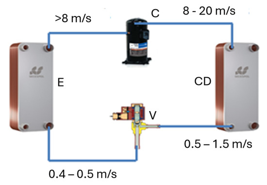
Figure 2.
Assumed velocity c of refrigerant in individual sections of the refrigeration system; C—compressor, CD—condenser, E—evaporator, V—expansion valve.
Thermodynamic calculations of the refrigeration system: heating power (Qh, kW), cooling capacity (Qc, kW), compressor capacity (Pc, kW) and V were carried out in the package Matlab&Simulink Thermolib.
3. Results
3.1. Stretch Film Production Line
The stretch film production process stages in the developed technological line are described below. The waste material (different suppliers) is subject to supply control (technological parameters, humidity), and excessive moisture requires drying the material. The heat exchanger powered by hot water (the upper heat source of the developed high-temperature HP using waste heat from the FCR) is the heat source in the dryer. The hot air flows through the bed and removes humidity. The dried material is sent to silos equipped with mixers (to average the raw material; new granulate is also fed 20%).
The mixture (pneumatic transport system) is delivered to the two twin-screw extruder tanks (Figure 3b). The material taken from the tanks melts (at 190–240 °C), moves (semi-liquid form) through the extruder channels (homogenization), then, as a result of intensive cooling, it solidifies and, escaping through the extruder nozzles, is cut into small granules (Figure 3a). In this way, regranulate is created, which, however, may have natural and artificial organic compounds (volatile substances). In the freshener, all volatile substances are removed (3 h, 60 °C).
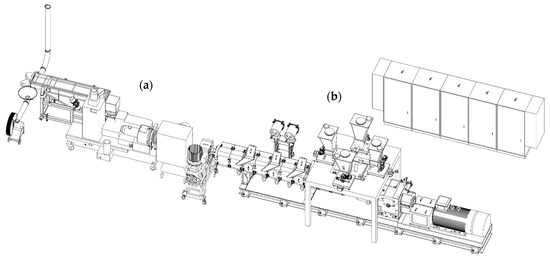
Figure 3.
The technological line for regranulate production; (a) cooling and cutting system, (b) twin screw extruder (co-rotating).
Then the material is transported (pneumatically) to the central part of the stretch film production line. Buffer tanks (Figure 4a,b,h) are filled with the supplied regranulate, from where it goes to six extruders (working simultaneously; Figure 4c), where it is melted (at 190–250 °C), and finally reaches the FCR in a semi-liquid form (Figure 4f). The FCR absorbs heat from the material, which in this way changes its state of matter (solid). Individual layers of the film are formed (thickness and width). The material (forming the film) passes to the next rotating rollers (rotation speed synchronized with the calender), where the layers of the film are stretched and connected (seven layers). The efficiency of film production of the stretch is about 7 tons/min (600 m/min). The stretch film is wound onto drums or rolls.
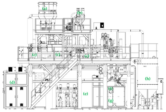
Figure 4.
The stretch film production line (cast method); (a) extruder buffer tank (4 pieces), (b) extruder buffer tank (2 pieces), (c) extruders (6 pieces), (d) control and monitoring system, (e) film cooling system, (f) FCR, (g) connection of cooling system of the FCR, (h) regranulate tank.
3.2. Process Line for Waste Heat Recovery
The stable operation of the stretch foil line producing and the high quality of the resulting product largely depend on the stable temperature of the FCR [36]. The FCR acts as a cooler, and the heat (waste heat) is so far dispersed in the environment. Additionally, adding recycled material (from various sources) to the base raw material makes it necessary to standardize it. The initial drying of the recycled material can use technological waste heat.
The designed technological heat recovery system in stretch foil line production is modular and consists of hydraulic systems separated by a heat exchanger (Figure 5).
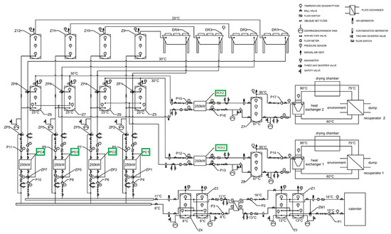
Figure 5.
Hydraulic system diagram—development version; DR—fan cooler, P—pump, PC—heat pump, PCh—high-temperature heat pump, Z—Buffer tank, ZM—mixing valve, ZP—switching valve.
HP evaporators (PC1-PC4) or fan coolers (DR1-DR4) supplied the primary side of the heat exchanger, while the load is the hydraulic system receiving heat from the FCR. This rotating cylinder’s stable (and uniform) surface temperature is ensured by the water flow (around 150 m3/h; inlet 15 °C, outlet 16 °C). Buffer tanks Z1 and Z2 (parallel connected) (2 m3 each) were proposed, constituting a cold storage (and increasing the water load in the installation), which translates into the inertia of the installation and a water pump P1 with smooth efficiency regulation (three-way mixing valve (ZM1) and regulators). The basic cooling sources (at the same time the first stage of heat recovery) are compressors of HP (in PC1–PC4 modules), for which the lower heat source is the heat necessary to cover the calender’s cooling demand. Heat pump evaporators are hydraulically coupled with Z1 and Z2 via Z3 and Z4 tanks (2 m3 each) and a heat exchanger (plate). This exchanger ensures, in the hydraulic system, the separation of glycol (primary side of the exchanger; heat or cooling carrier) and water (secondary side of the exchanger; technological cooling carrier). The role of Z3 and Z4 is to increase the glycol charge (system’s inertia) and, as a result, stabilize the temperature of the lower source of heat. The glycol flow between tanks Z3 and Z4 and the plate heat exchanger (primary side) is managed by pump P3 (with adaptable capacity control) to ensure a constant temperature difference of 3 K. This adaptability is also evident in the flow between tanks Z3 and Z4 and the HP evaporator, where the P4 pump, also with adaptable capacity control, is adjusted to the current evaporator heat load. The heat load of the PC1 condenser (and in the subsequent PC2–PC4 modules), depending on the mode of operation, can be buffered by Z5 and Z9 (2 m3 each) or the DR4 fan cooler.
HP mode of operation depends on the current demand for high-temperature heat (preparation of regranulate-drying). The appropriate three-way position switching valves, ZP1 and ZP2, are set. The position of these valves in B results in the supply of medium-temperature heat to Z5 and Z9, constituting the thermal load for the evaporator of the high-temperature HP PCh1. However, when there is no demand for heat (medium-temperature) or the temperature in tanks Z5 and Z9 has reached the set value, the following operating modes are possible. The first one is implemented when the ambient temperature >3 °C: PC1 is started, using technological heat (as the lower heat source; necessary for cooling FCR), the generated (medium-temperature) heat is dispersed in the environment thanks to DR4 (Z9 increases the glycol load, increases inertia). The second possible operating mode allows for the dispersion of process heat (medium-temperature) directly using DR4 (when the ambient temperature is <3 °C and the glycol temperature in tanks Z5 and Z9 has reached the set point), which enables significant savings in the electrical energy of the HP compressor. PCh1 generates high-temperature process heat, with Z5 being the lower heat source for PCh1 (when only one module is used). Tank Z8 is the PCh1 condenser heat load and a heat source (high-temperature) for the V-type heat exchanger 1. The air warms up as it passes through this exchanger, and then the drying chamber (drying the regranulate) and the recuperator (for reduced energy consumption) flow next.
A system of industrial control manages the discussed hydraulic system of the heat recovery operation. A layered structure (a classic) of the control system was adopted. The lowest layer comprises devices that generate/respond to input signals (information carriers about the system’s current state): temperature and flow sensors. Output devices (executive; directly affecting the control object) change the current state of the control object: valves, pumps, inverters.
3.3. Refrigerant
All selected refrigerants (38 refrigerants, using https://reftools.danfoss.com/spa/tools/ref-slider, accessed on 20 June 2025) for the refrigeration system of the technological heat recovery line are characterized by an ODP (determining the ozone depletion potential) coefficient value equal to zero.
The GWP coefficient value of the selected refrigerants ranges from 1 to 1397, which is why all refrigerants in the case of the implementation of a technological heat recovery device in the form of a two-stage device can be used in the lower stage of the device. However, in the upper stage of the device and the case of single-stage structures, only refrigerants with a GWP coefficient value of <150 can be used, which means that the number of possible refrigerants is 22 (from RE170 to R455A in Figure 6).
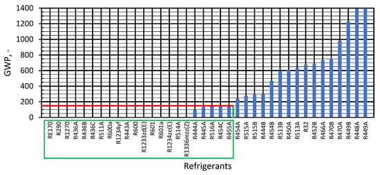
Figure 6.
Ranking of refrigerants by GWP.
When selecting the design of the refrigeration system, the temperature of the lower and upper source is an important parameter. For the designed process heat recovery line, the lower source temperature is the temperature of the medium cooling the FCR (15 °C). In contrast, the upper source temperature is the required temperature of the medium drying the recycled regranulate (designed 95 °C). Because the designed refrigeration system must be subcritical, the upper source temperature must be lower than the Tk of the refrigerant but should be higher than the required technological temperature (95 °C). Figure 7 presents a list of the selected refrigerants as a function of Tk (22 refrigerants meet the Tk > 95 °C criterion, from R601 to R444B). The Tk temperature of sixteen of the selected refrigerants (from R466A to R513A) is lower than the required technological temperature of 95 °C. In the lower stage of the refrigerant system, they can be used. However, to ensure the refrigeration device’s safe operation, the required Tk value has been increased to 105 °C, which extends the possibility of refrigerants in the lower stage (to 23, from R450A to R513A, Figure 7).
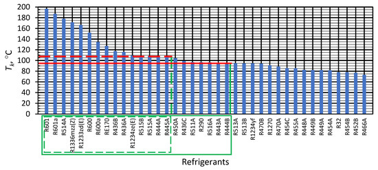
Figure 7.
Ranking of refrigerants according to Tk.
The following criterion is the refrigerant pressure (as a function of Ts), which should be higher than atmospheric pressure. The lowest value of Ts (from the point of view of the operation of the refrigeration device, from the recovery of technological heat, should be lower by 10–15 K) was assumed to be 0 °C. In contrast, the lowest limit value of ps was considered to be 2 Bar. Therefore, the refrigerants R600a, R600, R1233zd(E), R601a, R514A, and R1336mzz(Z) (Ts = 4.04 °C, ps = 0.3 Bar), R601 (Ts = 4.58 °C, ps = 0.3 Bar) could not be used in the first stage of the refrigeration device (Figure 8).
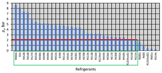
Figure 8.
Ranking of refrigerants concerning ps (for Ts = 0 °C).
The last criterion considered was the value of the critical point pressure (pk). For safety reasons and technological problems related to the implementation of the cooling system, it was assumed that pk should not be higher than 40 Bar. For this reason, the refrigerants from R290 to R32 (despite meeting the previously discussed criteria) should not be used in the second stage of the technological heat recovery device (Figure 9).
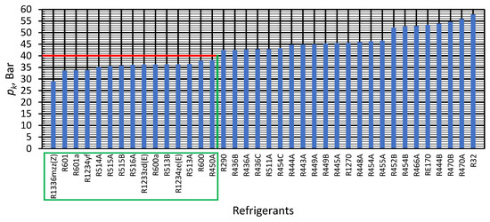
Figure 9.
Ranking of refrigerants according to pk.
Guided by the refrigerant selection, various manufacturers’ compressors were analyzed. The general criteria were the possibilities of: cooperation with R1234yf and R1234ze(E) refrigerants, tandem operation (which allows for adjustment of the nominal power (cooling and heating) of the designed devices to the demand for cooling and heat of the technological system), the possibility of regulating the efficiency of devices (frequency converter), oil replacement, resistance to a liquid agent flooding. The following compressor series were analyzed: scroll, rotary, piston, and screw. Bitzer semi-hermetic piston compressors were selected for further work.
3.4. Cooling System
In the case of implementing a technological heat recovery device in the form of the simplest single-stage refrigeration system (Figure 1a), the only possible refrigerant that meets all the assumed criteria would be R1234ze(E). This refrigerant belongs to the A2L group and is characterized by the lowest possible Ts of the refrigerant pressure: 2.17 Bar (Tk = 109.4 °C, pk = 36.35 Bar). Depending on the power of the available compressor series, the required heating power can be achieved with a single compressor or by connecting several compressors of lower power in parallel. The advantage of the proposed solution is the simple construction of the refrigeration system. Still, the main disadvantage is the large gradient between the minimum assumed Ts of the refrigerant and the maximum assumed condensation temperature (95 °C). Such a significant temperature difference will require the compressor to operate with high volumetric efficiency, negatively affecting its service life.
The indicated problem can be eliminated using a two-stage system (two compressors in series connection; one in the lower and the other in the refrigeration system; Figure 1b). In the absence of a single compressor with the required power (similarly to the single-stage system), two or more parallel compressors with lower power should be used in each stage. The advantage of such a solution is reducing the compressor wear rate by adjusting the intermediate temperature depending on the current required temperature level of the upper source. At the same time, the disadvantage (regardless of the demand for high-temperature heat) is the need to operate both stages of the device.
Considering the possible limitations resulting from the range of the lower and upper source of the compressor’s operating envelope, the possibility of implementing the refrigeration system of the technological heat recovery device in the form of a cascade system was also considered (Figure 1c). In the upper stage of the cascade, the R1234ze(E) refrigerant was used, while in the lower stage (due to the highest-pressure value (for Ts = 0 °C): 3.16 Bar and belonging to the A2L group) the R1234yf refrigerant was used. The advantage of the device’s refrigeration system is obtaining a wide range of lower source temperatures regardless of the upper source temperature range. However, the main limitation is the selection of compressor power (lower and upper cascade stages). The selection of compressor power for the lower cascade stage is dictated by the power of cooling required to prepare the technological cold of the FCR. The result is the heating power of the condenser, which determines the cooling power of the upper stage of the cascade. In operating conditions, the power of cooling of the upper stage of the cascade depends on the condensation temperature of the second stage of the cascade, which causes certain inconveniences in the operation of such a device (the need to adjust the power of heating of the first stage depending on the current demand for high-temperature technological heat). This problem can be eliminated to some extent by regulating the volumetric efficiency of the compressors of the first and second stages of the cascade, with the priority of the device operation being to cover the demand for technological cooling of the FCR.
The main disadvantage of the considered solutions of the two-stage and cascade refrigeration system is the necessity of operating both stages simultaneously (even in the absence of demand for high-temperature process heat), which generates increased electricity consumption. The solution to this problem is implementing a process heat recovery system in the form of two single-stage low- and high-temperature refrigeration devices coupled hydraulically. Such a solution generates higher investment costs (the cost of making two separate refrigeration devices and the fittings necessary to make the hydraulic installation). Still, it provides much greater possibilities for flexible adjustment of low- and high-temperature device efficiency to the current demand for cooling and processing heat (this will translate into a reduction in electricity consumption).
Considering the advantages and disadvantages in all aspects of possible design solutions for refrigeration systems, it was decided that the most significant compromise between all the elements analyzed will be obtained using two single-stage devices coupled hydraulically. The low-temperature refrigeration device will be used with the selected R1234yf refrigerant, while the high-temperature device will use the R1234ze(E) refrigerant. The lower heat source of the low-temperature heat pump will be the liquid transferring heat from the FCR, while its upper heat source will be the liquid, which will also serve as the lower heat source of the high-temperature heat pump. The upper heat source of the high-temperature heat pump will be the liquid supplying the regranulate dryer heater (heating the drying air).
3.5. Heat Pump
Taking into account technological (power, refrigerant) and economic (investment and operation: possible replacement of operating fluids (oil), filters, possibility of regeneration) considerations, the designed heat pumps use semi-hermetic Bitzer piston compressors.
3.5.1. Low Temperature HP
The low-temperature subcritical compressor HP uses parallel-connected (semi-hermetic, piston) 8FE-60Y compressors. The Ts range of the R1234yf refrigerant is from −20 °C to 25 °C. In contrast, the condensation range is from 20 °C to 80 °C (Figure 10a). Considering technological considerations (coolant temperature in the FCR: 15 °C, the evaporator is a plate heat exchanger, the difference between the Ts of the refrigerant and the lower heat source temperature: 10 K), 5 °C was assumed as the design (nominal) Ts of the refrigerant. The condensation temperature of the refrigerant was assumed as (for Ts = 5 °C and considering the work envelope for the high-temperature subcritical heat pump compressor with the 1234ze(E) refrigerant): 35 °C. The refrigerant superheating was also assumed to be 10 K and subcooling to be 5 K (Figure 10b).
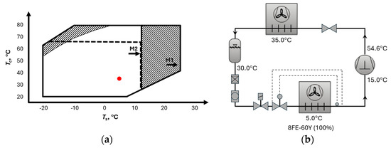
Figure 10.
Operating envelope of the 8FE-60Y compressor;  suction gas superheat ≤20 K,
  suction gas superheat >10 K,
  M1 motor 1,
  M2 motor 2,
  A (a) and parameters of a low-temperature HP (b).
suction gas superheat ≤20 K, suction gas superheat >10 K, M1 motor 1, M2 motor 2, A (a) and parameters of a low-temperature HP (b).
3.5.2. High Temperature HP
The high-temperature compressor HP uses parallel-connected (semi-hermetic, piston) 6FEH-50Y compressors. The Ts range of the R1234yf refrigerant is from −15 °C to 35 °C, while Tc is from −10 °C to 95 °C (Figure 11a). Considering the technical parameters of the low-temperature heat pump (temperature of the upper heat source 25–50 °C, the evaporator is a plate heat exchanger, the difference between the Ts of the refrigerant and the temperature of the lower heat source: 10 K), the possible range of Ts of the refrigerant was established: 16 °C ÷ 30 °C. For a high-temperature subcritical HP powered by a 1234ze(E) refrigerant, taking into account Ts = 35 °C and the compressor operating envelope, the refrigerant condensation temperature was assumed to be 85 °C (the upper heat source range was considered to be 75–85 °C—technological process requirements). The refrigerant superheating was believed to be 10 K, and subcooling was 5 K (Figure 11b).
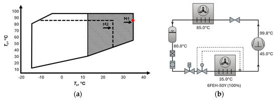
Figure 11.
Operating envelope of the 6FEH-50Y compressor; suction  gas superheat >10 K,
  M1 motor 1,
  M2 motor 2,
  A (a), parameters of a high-temperature HP (b).
gas superheat >10 K, M1 motor 1, M2 motor 2, A (a), parameters of a high-temperature HP (b).
3.6. Heat Pump Simulation Studies
Simulation studies made it possible to determine (with the assumed heat pump working space): cooling and heating power, electrical energy consumed by the compressor (consequently the COP coefficient), heat exchange rate (W/K) (evaporator and condenser; necessary for the complete phase change in the refrigerant), and to determine the required flow of the working medium (heat carrier of the technological heat recovery line) for the assumed design work gradients (primary side of the evaporator: 3 K, secondary side of the condenser: 5 K). Simulation studies began with implementing the refrigeration system in MATLAB and Simulink Thermolib. From a design point of view, it was then important to determine the value of the total heat loss coefficient (evaporator and condenser) as a function of M of the medium (on the primary side-evaporator and on the secondary side-condenser (Figure 12).
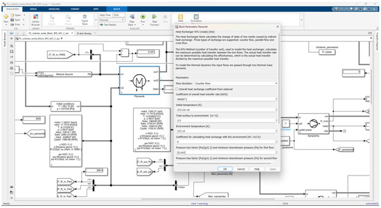
Figure 12.
Configuration of exchanger parameters in the MATLAB and Simulink Thermolib package.
3.6.1. Low Temperature HP
Figure 13 shows the influence of refrigerant saturation and condensation temperatures on the mass flow of R1234yf refrigerant for a compressor volumetric capacity of 0.061 m3/s (and specific steam volume at the suction nozzle).
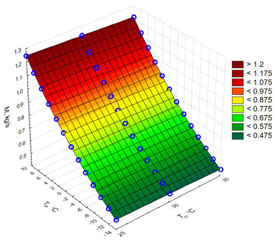
Figure 13.
Mass flow of the refrigerant in a low-temperature HP for the assumed design Ts and Tc of the R1234yf refrigerant.
In the evaporator of a low-temperature HP, water is the medium on the primary side, while in the condenser (secondary side), a 40% ethylene glycol solution (freezing point −35 °C).
The most unfavourable operating point of HP (the highest heating and cooling power) was determined, the total heat loss coefficient of the exchanger was determined for it (so that the refrigerant changes its state: evaporator from liquid to gas, condenser from gas to liquid) for the assumed temperature gradient and then the flow of the medium (evaporator and condenser) was determined. For all other operating points (in the working area), the selected heat exchange surface (condenser and evaporator) will be greater than the required minimum, which will cause the refrigerant to change its state of matter constantly. In the case of 1234yf, the most unfavourable operating point is the highest Ts and the lowest Tc, due to which the heat transfer coefficient of the condenser was 84 kW/K and the evaporator 132 kW/K.
The results of the calculations for a low-temperature HP (Tc: 25 ÷ 50 °C, Ts: −6 ÷ 10 °C) are shown in Figure 14.
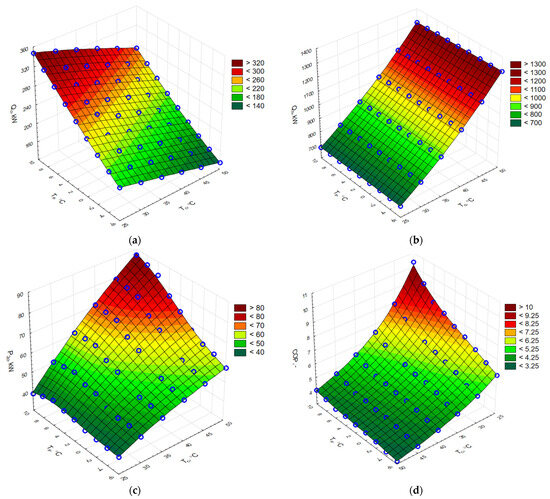
Figure 14.
The influence of Tc and Ts on: (a) Qc, (b) Qh, (c) P2c, and (d) COP of the low-temperature HP (100% control of both compressors).
The cooling capacity (Figure 14a), heating power (Figure 14b) and COP (Figure 14d) increase with increasing Ts and decreasing Tc, while the power of the two compressors (Figure 14c) increases with increasing both Ts and Tc. The available power of cooling corresponds to the technological cooling of the FCR of the technological line for foil production. Therefore, the nominal operating point of the HP is: Ts = 4 °C and Tc = 35 °C.
The tested heat pump generates the highest Qh (approx. 400 kW) at Ts of the refrigerant 10 °C (highest design) and Tc = 25 °C (lowest design) and for this operating point P2c is the lowest (approx. 39 kW; Figure 14c) and the COP is the highest (approx. 10; Figure 14d). An increase in Tc from 25 °C to 50 °C (constant Ts and Ts = 10 °C) causes a decrease in Qh by approx. 13% and at the same time an increase in P2c by as much as approx. 120%. The heat pump generates the lowest Qh (approx. 180 kW) at Ts = −6 °C (lowest design) and its Tc 50 °C (highest design), with a P2c demand of approximately 58 kW.
Analyzing P2c controlled at 100% as a function of Ts of the refrigerant (Figure 14c), it can be seen that for the lowest Tc value (25 °C) in the entire range of Ts of the refrigerant, the P2c is practically constant (approx. 40 kW). The increase in Tc increases the consumption of electric energy, especially at higher Ts (up to approx. 90 kW for the highest Tc: 50 °C and Ts = 10 °C).
The greatest variation in the heat pump COP coefficient is characterized by the lowest Tc (25 °C; in the entire range of Ts): from approx. 10 (Ts = 10 °C) to approx. 6 (Ts = −6). There is a small variation in the COP at the highest Tc of 50 °C: on average, about 4. The COP for the nominal operating point (Ts = 4 °C and Tc = 35 °C) is about 5.5.
The results of simulation studies of the working medium flow (water) on the primary side of the evaporator and the secondary side of the condenser (glycol) are presented in Figure 15. The required V of the medium (for both the evaporator and the condenser) increases linearly with the increase in the lower source temperature (constant Tc of the refrigerant). The biggest V was for the highest Ts (10 °C) and the lowest Tc (25 °C): 0.037 m3/s for the evaporator and 0.026 m3/s for the condenser. The calculation results enabled the selection of circulation pumps.
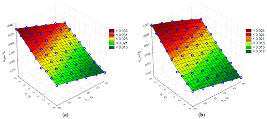
Figure 15.
Volume flow (V) of the working medium through the evaporator (a) and the condenser (b) of a low-temperature HP (100% control of both compressors).
3.6.2. High Temperature HP
Figure 16 shows the influence of the refrigerant Ts and Tc on M of the R1234yf refrigerant for a compressor volumetric capacity of 0.043 m3/s and for the value of the specific volume of steam at the suction nozzle.
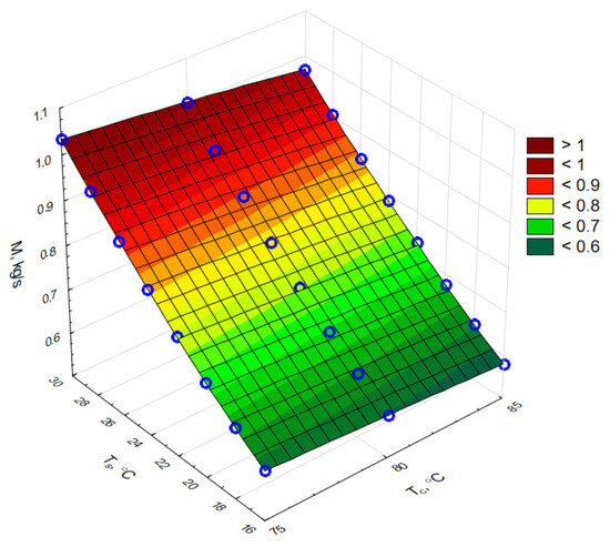
Figure 16.
Mass flow (M) of the refrigerant in a high-temperature HP for the assumed design Ts and Tc.
In the case of the evaporator and condenser of the high-temperature HP, the medium used was a 40% ethylene glycol solution (temperature of solidification −35 °C). The results of the calculations carried out for the high-temperature HP (Tc: 75 ÷ 80 °C, Ts: 16 ÷ 30 °C) are shown in Figure 17.
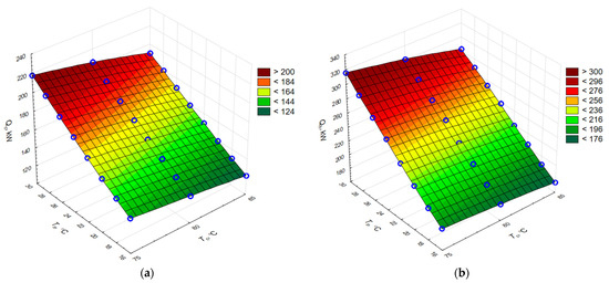
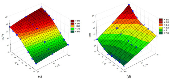
Figure 17.
The influence of Tc and Ts on: (a) Qc, (b) Qh, (c) P2c, and (d) COP of the high-temperature HP (100% control of both compressors).
The cooling capacity (Figure 17a), heating capacity (Figure 17b) and COP (Figure 17d) increase with increasing Ts and decreasing Tc, while P2c (Figure 17c) increases with increasing both Ts and Tc. The highest cooling capacity (the most unfavourable operating point) occurs for the highest Ts and the lowest Tc (30 and 75 °C, respectively): about 220 kW, whereas the lowest (about 130 kW) occurs for the lowest Ts and the highest Tc (16 and 85 °C, respectively).
The tested heat pump generates the highest Qh (approx. 320 kW) at Ts = 30 °C (the highest design) and Tc = 75 °C (the lowest design) and for this operating point P2c (approx. 85 kW; Figure 17c) and the COP (approx. 3.7; Figure 17d) are the highest. An increase in Tc from 75 °C to 85 °C (constant Ts, Ts = 10 °C) causes a decrease in Qh by approximately 10% and a simultaneous rise in P2c by about 10%. The heat pump generates the lowest Qh (approx. 170 kW) at Ts = 16 °C (the lowest design) and Tc = 85 °C (the highest design), with P2c of approx. 68 kW.
The analysis of P2c as a function of Ts (Figure 17c) shows that the increase in Tc increases the consumption of electric energy, especially at higher Ts (up to approximately 95 kW for the highest Tc = 85 °C and Ts = 30 °C). The COP coefficient does not show much variation. It reaches the highest value (approx. 3.7) for the operating point of 30 °C and 75 °C (Ts and Tc, respectively) and the lowest (approx. 2.8) for 16 °C and 85 °C (Ts and Tc, respectively).
The results of simulation studies of the glycol (working medium) flow on the primary side of the evaporator and the secondary side of the condenser are presented in Figure 18. The required V (for both the condenser and the evaporator) increases linearly with the increase in the lower source temperature (constant Tc of refrigerant). The values of the largest V were obtained for the highest Ts (30 °C) and the lowest Tc (75 °C), amounting to about 0.022 m3/s for the evaporator and about 0.018 m3/s for the condenser. The calculation results enabled the selection of circulation pumps.
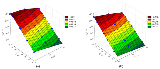
Figure 18.
Volume flow (V) of the working medium through the evaporator (a) and the condenser (b) of a high-temperature HP (100% control of both).
4. Conclusions
An innovative line for waste heat recovery in the energy-saving technology of stretch film production, where waste heat is transformed into high-temperature heat. This heat is then used in the process of raw material standardization. Because raw material can contain up to 80% of recyclates, it is characterized by very variable parameters. The developed heat recovery line is based on two hydraulically coupled compressor heat pumps (HP): low-temperature HP and high-temperature HP. The HP use ecological refrigerants R1234ze(E) (low-temperature HP) and R1234yf (high-temperature HP) (used criteria: GWP < 150, pk < 40 Bar, Tk > 95 °C (for high-temperature HP), ps >2 Bar).
The work uses Bitzer software v7.0.5.4, Matlab R2024b and Simulink Thermolib package 5.4 and SolidWorks software 2021. The computer simulations performed concern a wide range of condensation temperatures (25–50 °C) and condensation (from −6 to 10 °C) of refrigerants; the values of the HP mass flow of refrigerant (0.4–1.3 kg/s and 0.6–1.0 kg/s for low- and high-temperature HP, respectively), heating power (0.7–1.3 MW and 0.2–0.3 MW for low- and high-temperature HP, respectively), COP coefficient (3–10 MW and 2.7–3.7 MW for low- and high-temperature HP, respectively), and the mass flows of the working medium (water/glycol) flowing through heat exchangers (evaporator: 0.015–0.037 m3/s and 0.013–0.022 m3/s and condenser: 0.012–0.26 m3/s and 0.010–0.019 m3/s for low- and high-temperature HP, respectively) were determined.
The developed solution reduces energy consumption and CO2 emissions and implements a closed-loop economy based on renewable energy sources (according to the European Green Deal). The consortium leader (TW Plast) is implementing the developed technology, which may be the basis for similar systems in other technological processes. Further work is aimed at ensuring energy and ecological security through waste heat.
Author Contributions
Conceptualization, K.G., and P.O.; methodology, P.O. and K.G.; software, P.O. and K.G.; validation, K.G. and P.O.; formal analysis, P.O., K.G., and K.T.; data curation, P.O.; writing—original draft preparation, K.G.; writing—review and editing, K.G.; visualization, K.T. and K.G.; project administration, P.O.; funding acquisition, K.G. All authors have read and agreed to the published version of the manuscript.
Funding
This research was funded by the National Centre for Research and Development, Poland, grant number: POIR.01.01.01-00-1078/21.
Data Availability Statement
Data are contained within the article.
Conflicts of Interest
The authors declare no conflicts of interest.
References
- European Parliament. Topics. Plastic Waste and re Cycling in the EU: Facts and Figures. 25 June 2024. Available online: https://www.europarl.europa.eu/topics/en/article/20181212STO21610/plastic-waste-and-recycling-in-the-eufacts-and-figures (accessed on 20 May 2025).
- Alsabri, A.; Tahir, F.; Al-Ghamdi, S.G. Environmental Impacts of Polypropylene (PP) Production and Prospects of Its Recycling in the GCC Region. Mater. Today Proc. 2022, 56, 2245–2251. [Google Scholar] [CrossRef]
- Wongsirichot, P. Natural Renewable Polymers Part I: Polysaccharides. In Encyclopedia of Green Chemistry; Reference Module in Chemistry, Molecular Sciences and Chemical Engineering; Elsevier: Amsterdam, The Netherlands, 2024; pp. 154–173. ISBN 978-0-12-409547-2. [Google Scholar]
- Chen, X.; Chen, S.; Xu, Z.; Zhang, J.; Miao, M.; Zhang, D. Degradable and Recyclable Bio-Based Thermoset Epoxy Resins. Green Chem. 2020, 22, 4187–4198. [Google Scholar] [CrossRef]
- Thakur, M.; Sharma, A.; Chandel, M.; Pathania, D. Modern Applications and Current Status of Green Nanotechnology in Environmental Industry. In Green Functionalized Nanomaterials for Environmental Applications; Elsevier: Amsterdam, The Netherlands, 2022; pp. 259–281. ISBN 978-0-12-823137-1. [Google Scholar]
- Singh, J.; Krasowski, A.; Singh, S.P. Life Cycle Inventory of HDPE Bottle-based Liquid Milk Packaging Systems. Packag. Technol. Sci. 2011, 24, 49–60. [Google Scholar] [CrossRef]
- Sharma, B.; Goswami, Y.; Sharma, S.; Shekhar, S. Inherent Roadmap of Conversion of Plastic Waste into Energy and Its Life Cycle Assessment: A Frontrunner Compendium. Renew. Sustain. Energy Rev. 2021, 146, 111070. [Google Scholar] [CrossRef]
- Sarker, M.; Kabir, A.; Rashid, M.M.; Molla, M.; Din Mohammad, A.S.M. Waste Polyethylene Terephthalate (PETE-1) Conversion into Liquid Fuel. J. Fundam. Renew. Energy Appl. 2011, 1, 1–5. [Google Scholar] [CrossRef]
- Spilka, M.; Kania, A.; Nowosielski, R. Integrated Recycling Technology. J. Achiev. Mater. Manuf. Eng. 2008, 31, 97–102. [Google Scholar]
- Balu, R.; Dutta, N.K.; Roy Choudhury, N. Plastic Waste Upcycling: A Sustainable Solution for Waste Management, Product Development, and Circular Economy. Polymers 2022, 14, 4788. [Google Scholar] [CrossRef] [PubMed]
- Chen, H.; Wan, K.; Zhang, Y.; Wang, Y. Waste to Wealth: Chemical Recycling and Chemical Upcycling of Waste Plastics for a Great Future. ChemSusChem 2021, 14, 4123–4136. [Google Scholar] [CrossRef] [PubMed]
- Hou, Q.; Zhen, M.; Qian, H.; Nie, Y.; Bai, X.; Xia, T.; Laiq Ur Rehman, M.; Li, Q.; Ju, M. Upcycling and Catalytic Degradation of Plastic Wastes. Cell Rep. Phys. Sci. 2021, 2, 100514. [Google Scholar] [CrossRef]
- Ellis, L.D.; Rorrer, N.A.; Sullivan, K.P.; Otto, M.; McGeehan, J.E.; Román-Leshkov, Y.; Wierckx, N.; Beckham, G.T. Chemical and Biological Catalysis for Plastics Recycling and Upcycling. Nat. Catal. 2021, 4, 539–556. [Google Scholar] [CrossRef]
- Adoption. Adoption of the Paris Agreement. In Proceedings of the United Nations Framework Convention on Climate Change Conference of the Parties Twenty-First Session, Paris, France, 30 November–11 December 2015; Available online: https://unfccc.int/resource/docs/2015/cop21/eng/l09r01.pdf (accessed on 20 May 2025).
- Kanai, T.; Cakmak, M.; Polymer Processing Society (Eds.) Film Processing; Progress in Polymer Processing; Hanser/Gardner: Cincinnati, OH, USA, 1999; ISBN 978-1-56990-252-3. [Google Scholar]
- Thuy, V.T.T.; Hao, L.T.; Jeon, H.; Koo, J.M.; Park, J.; Lee, E.S.; Hwang, S.Y.; Choi, S.; Park, J.; Oh, D.X. Sustainable, Self-Cleaning, Transparent, and Moisture/Oxygen-Barrier Coating Films for Food Packaging. Green Chem. 2021, 23, 2658–2667. [Google Scholar] [CrossRef]
- Politaki, D.; Alouf, S. Stochastic Models for Solar Power. In Computer Performance Engineering; Reinecke, P., Di Marco, A., Eds.; Lecture Notes in Computer Science; Springer International Publishing: Cham, Switzerland, 2017; Volume 10497, pp. 282–297. ISBN 978-3-319-66582-5. [Google Scholar]
- Kumar, J.C.R.; Majid, M.A. Renewable Energy for Sustainable Development in India: Current Status, Future Prospects, Challenges, Employment, and Investment Opportunities. Energy Sustain. Soc. 2020, 10, 2. [Google Scholar] [CrossRef]
- Attanayake, K.; Wickramage, I.; Samarasinghe, U.; Ranmini, Y.; Ehalapitiya, S.; Jayathilaka, R.; Yapa, S. Renewable Energy as a Solution to Climate Change: Insights from a Comprehensive Study across Nations. PLoS ONE 2024, 19, e0299807. [Google Scholar] [CrossRef] [PubMed]
- Spitler, J.; Gehlin, S. Measured Performance of a Mixed-Use Commercial-Building Ground Source Heat Pump System in Sweden. Energies 2019, 12, 2020. [Google Scholar] [CrossRef]
- Ozyurt, O.; Ekinci, D.A. Experimental Study of Vertical Ground-Source Heat Pump Performance Evaluation for Cold Climate in Turkey. Appl. Energy 2011, 88, 1257–1265. [Google Scholar] [CrossRef]
- Correa-Quintana, E.; Muñoz-Maldonado, Y.; Ospino-Castro, A. Financial Evaluation of Alternatives for Industrial Methanol Production Using Renewable Energy with Heat Pump Technology. Energies 2024, 17, 5560. [Google Scholar] [CrossRef]
- Chen, H.; Guo, S.; Song, X.; He, T. Design and Evaluation of a Municipal Solid Waste Incineration Power Plant Integrating with Absorption Heat Pump. Energy 2024, 294, 131007. [Google Scholar] [CrossRef]
- Ghaderi, M.; Reddick, C.; Sorin, M. A Systematic Heat Recovery Approach for Designing Integrated Heating, Cooling, and Ventilation Systems for Greenhouses. Energies 2023, 16, 5493. [Google Scholar] [CrossRef]
- Ma, D.; Sun, Y.; Ma, S.; Li, G.; Zhou, Z.; Ma, H. Study on the Working Medium of High Temperature Heat Pump Suitable for Industrial Waste Heat Recovery. Appl. Therm. Eng. 2024, 236, 121642. [Google Scholar] [CrossRef]
- Calleja-Anta, D.; Nebot-Andres, L.; Cabello, R.; Sánchez, D.; Llopis, R. A3 and A2 Refrigerants: Border Determination and Hunt for A2 Low-GWP Blends. Int. J. Refrig. 2022, 134, 86–94. [Google Scholar] [CrossRef]
- Ally, M.R.; Sharma, V.; Nawaz, K. Options for Low-Global-Warming-Potential and Natural Refrigerants Part I: Constrains of the Shape of the P–T and T–S Saturation Phase Boundaries. Int. J. Refrig. 2019, 106, 144–152. [Google Scholar] [CrossRef]
- Nawaz, K.; Ally, M.R. Options for Low-Global-Warming-Potential and Natural Refrigerants Part 2: Performance of Refrigerants and Systemic Irreversibilities. Int. J. Refrig. 2019, 106, 213–224. [Google Scholar] [CrossRef]
- Jakubowska, P.; Sterzyński, T.; Królikowski, B. The Properties of Polyolefins Modified with PET Powder. J. Appl. Polym. Sci. 2008, 109, 1993–1999. [Google Scholar] [CrossRef]
- Demay, Y.; Agassant, J.F. The Polymer Film Casting Process—An Overview. Int. Polym. Process. 2021, 36, 264–275. [Google Scholar] [CrossRef]
- Jouhara, H.; Żabnieńska-Góra, A.; Delpech, B.; Olabi, V.; El Samad, T.; Sayma, A. High-Temperature Heat Pumps: Fundamentals, Modelling Approaches and Applications. Energy 2024, 303, 131882. [Google Scholar] [CrossRef]
- Regulation (EU) 2024/573 of the European Parliament and of the Council of 7 February 2024 on Fluorinated Greenhouse Gases, Amending Directive (EU) 2019/1937 and Repealing Regulation (EU) No 517/2014. Available online: https://eur-lex.europa.eu/eli/reg/2024/573/oj/eng (accessed on 20 May 2025).
- IEC 60335-2-89; Household and Similar Electrical Appliances—Safety—Part 2-89: Particular Requirements for Commercial Refrigerating Appliances and Ice-Makers with an Incorporated or Remote Refrigerant Unit or Motor-Compressor. IEC: Geneva, Switzerland, 2023.
- IEC 60335-2-40; Household and Similar Electrical Appliances—Safety—Part 2-40: Particular Requirements for Electrical Heat Pumps, Air-Conditioners and Dehumidifiers. IEC: Geneva, Switzerland, 2024.
- Bitzer Software. Available online: https://www.bitzer.de/websoftware/calculate/hhk/?Tab=results (accessed on 1 May 2024).
- Dziadowiec, D.; Matykiewicz, D.; Szostak, M.; Andrzejewski, J. Overview of the Cast Polyolefin Film Extrusion Technology for Multi-Layer Packaging Applications. Materials 2023, 16, 1071. [Google Scholar] [CrossRef] [PubMed]
Disclaimer/Publisher’s Note: The statements, opinions and data contained in all publications are solely those of the individual author(s) and contributor(s) and not of MDPI and/or the editor(s). MDPI and/or the editor(s) disclaim responsibility for any injury to people or property resulting from any ideas, methods, instructions or products referred to in the content. |
© 2025 by the authors. Licensee MDPI, Basel, Switzerland. This article is an open access article distributed under the terms and conditions of the Creative Commons Attribution (CC BY) license (https://creativecommons.org/licenses/by/4.0/).