Article

Non-Linear Analytical Model for Bread-Loaf Linear PM Motor

1
Department of Electrical Engineering, Yildiz Technical University, Davutpasa 34220, Turkey
2
Department of Electrical and Information Engineering (DIEI), University of Cassino and Southern Lazio, 03043 Cassino, Italy
*
Authors to whom correspondence should be addressed.
Energies 2025, 18(15), 3940; https://doi.org/10.3390/en18153940
Submission received: 27 March 2025 / Revised: 9 June 2025 / Accepted: 12 June 2025 / Published: 24 July 2025
(This article belongs to the Special Issue Condition Monitoring of Electrical Machines Based on Models)

Abstract

This article presents a non-linear MEC for a linear PM motor, and its experimental validation. In the MEC model, winding flux leakage and iron saturation are considered. In addition, two different linear PM motor models (bread-loaf and surface-type) are examined for linear PM motors. An iterative method is used to predict the magnetic behavior of saturated magnetic steel. The proposed MEC for linear PM motors is compared with finite element analysis (FEA) to determine its accuracy and suitability. FEA is widely regarded as a highly accurate and reliable tool for analyzing linear PM motors. However, its primary limitation lies in its considerable computational time requirement. This disadvantage becomes particularly problematic during the early stages of the design process. Therefore, the proposed model addresses this limitation. Also, experimental results validate the practicality of the MEC. Finally, the proposed model can be a tool for different slot/pole combinations. Thus, the model can be considered suitable for both bread-loaf and surface-type PM motors.

1. Introduction

Linear motors have a high ability to generate high thrusting force in a straight axis. In electromagnetic systems, there are linear analogies of all rotating electrical motors. Linear motors are generally classified into three different types: electrically excited synchronous motors, synchronous reluctance motors (SynRMs), and PM synchronous motors [1]. PM synchronous motors are widely used in speed- and position-controlled systems due to their high efficiency, robust structure, and high torque density [2]. Linear PM motors have similar advantages and disadvantages to rotational PM motors. In the design of a linear PM motor, the main objectives to be considered are efficiency, force fluctuation, and reduction of detent force [3]. To fulfill these purposes, electromagnetic performance-enhancing methods should be used in the design [4].
An accurate electromagnetic model is required to achieve the design phase objectives of the linear PM motor. To obtain electromagnetic performance criteria in electric motors, Maxwell’s equations are solved based on partial differential equations. The solution of these equations is basically defined analytically and numerically [5]. Numerical methods have been used extensively by researchers until now. FEA is capable of predicting electromagnetic performance with high accuracy, regardless of magnetic and geometric complexities [6]. There have been numerous studies on the design of linear PM motors based on FEA [7,8,9]. However, its main disadvantage is that its time-consuming although it has high accuracy. For each geometrical change, including linear PM motor motion, the analysis is resolved again. Hence, it is applicable for the early design stage of linear PM motors [4].
The other methods of solving Maxwell’s equations are analytical methods. These methods aim to handle FEA’s high time-consuming feature [10]. To spend less time, it assumes certain conditions for analysis. Because of the assumptions it considers, the accuracy of electromagnetic performance may vary depending on the researcher’s knowledge of the behavior of the magnetic system. In the literature, analysis of electrical motors is examined with three different approaches in terms of dimensions [11]: one-dimensional (1-D), two-dimensional (2-D), and three-dimensional (3-D), while it is examined as slotless and slotted according to the slot structure [5]. Analytical models in the literature, both in size and in terms of slot structure, are the MEC, sub-domain, relative permeance model, and complex permeance model. The sub-domain predicts the magnetic field distribution based on the analytical approach of Maxwell’s equations [12]. It is solved by Fourier series with the assignment of boundary conditions in different regions [13]. This method can easily calculate the air-gap magnetic flux (MF) distribution of a linear PM motor at any point radially and tangentially as accurately as FEA. In the literature, a sub-domain is proposed by different studies such as a flux-switching PM motor [14], induction motor [6,15,16], spoke PM motor [17], dual stator spoke PM motor [18], inset PM motor [19,20,21], surface PM motor [22,23,24], linear PM motor [25], and axial flux PM motor [13,26,27]. Another analytical method is conformal mapping, which considers the slot effect. Conformal mapping (CM) has been studied under two main headings: relative permeance model and complex permeance model [5]. While the relative permeance model is analyzed in 1-D, the complex permeance model is analyzed in 2-D [4]. CM analysis is performed in a unique way. It solves a partial differential equation by transforming between coordinate systems. In the literature, CM is proposed by different studies such as a flux-switching PM motor [28], bread-loaf PM motor [22], spoke PM motor [29,30], inset PM motor [31], surface PM motor [32,33,34,35], transverse-flux PM motor [36,37], SynRM [38], and axial flux PM motor [39]. CM and the sub-domain method analyze by assuming the magnetic core permeability as infinite [6]. The last analytical method is the MEC. It differs from the aforementioned analytical models. Unlike the sub-domain method and CM, this method can consider the non-linear magnetic core feature and analyze any structure geometrically [40]. Because of these features, it is also called the semi-analytical method. Analysis of this method is based on Kirchoff’s current and voltage laws by creating flux tubes [41]. However, accurate estimation of flux paths is difficult and requires experience, so it cannot be predicted with very high accuracy. In the literature, the MEC is proposed by different studies such as an induction motor [42], spoke PM motor [43], interior PM motor [44,45,46], surface PM motor [47,48], SynRM [5], dual stator PM motor [4], switch reluctance motor (SRM) [49,50], linear SRM [48], flux-switching PM motor [49,50,51], axial flux PM motor [51,52,53,54,55,56,57,58,59,60,61], linear vernier PM motor [13,62], and linear PM motor [63,64,65,66,67,68,69,70]. Analytical methods in the literature are classified in Table 1.
In the literature, precious and valuable contributions have been made on modeling techniques so far. However, these contributions failed to mention the following concerns. First, the analytical method of the bread-loaf linear PM motor was not examined in these studies. Second, the back electromagnetic force (EMF) of the bread-loaf PM linear motor is like a sinus waveform and is very suitable in AC systems. In addition, in these studies, electromagnetic performance criteria were generally obtained with the radial component of air-gap MF density in [62,63,64,65,66,67,68,69,70]. Ignoring the tangential component of air-gap MF density creates two problems: ignoring winding leakage fluxes and the Maxwell Stress Tensor (MST).
The MST is widely applied in electromagnetic analysis tools such as Ansys and FEMM. Third, obtaining experimental results is important in terms of proving that the result obtained from numerical and analytical results can be used in practice. However, some studies did not validate analytical results by experimental results [63,64,65,66,67,68,69,70].
In [62,63,65], saturation is considered in the MEC. Also, a force equation is calculated according to the Lorenz Force Law. However, FEA is commonly solved based on the Maxwell Stress Tensor method to calculate the force for high accuracy. Also, the leakage flux is not considered. In [64,66,67,68,69,70], a linear PM machine is analyzed by the Lumped Parameter Method. In these studies, the saturation condition is considered in some and not in others. In addition, this method is inherently less accurate and difficult to model. It does not consider leakage fluxes, and the Maxwell Stress Tensor cannot be used. Therefore, this study is proposed to overcome these difficulties in the literature. The solution is based on the Maxwell Stress Tensor for more similar accuracy with FEA. Leakage fluxes and saturation are considered. Due to the air-gap model, it is not difficult to model, and the accuracy is high. In addition to the studies in the literature, a bread-loaf type PM motor is analyzed, and test results are shared.
This study proposes an experimentally validated two-dimensional MEC model for bread-loaf linear PM motors, accurately accounting for magnetic saturation, leakage fluxes, and tangential fields, while significantly reducing computation time compared to FEA.
The organization is as follows: The second section shows the linear PM motor structure and proposed model. In the third section, the proposed model is validated by FEA and experimental results. The fourth section covers the conclusion.

2. Proposed Model

The parts belonging to the linear PM motor structure are shown in Figure 1. The moving part is introduced as a stator and the fixed part is introduced as a rotor. There are two different winding techniques in electrical motors. These are concentrated winding and distributed winding types. The concentrated one is generally used in linear PM motors. The winding schemas of bread-loaf and surface linear PM motors are presented in Figure 2. Additionally, arrows indicate the directions of the windings, showing from which slot they come out and into which slot they enter. The basic parameters of linear PM motors shown in Figure 1 are presented in Table 2.

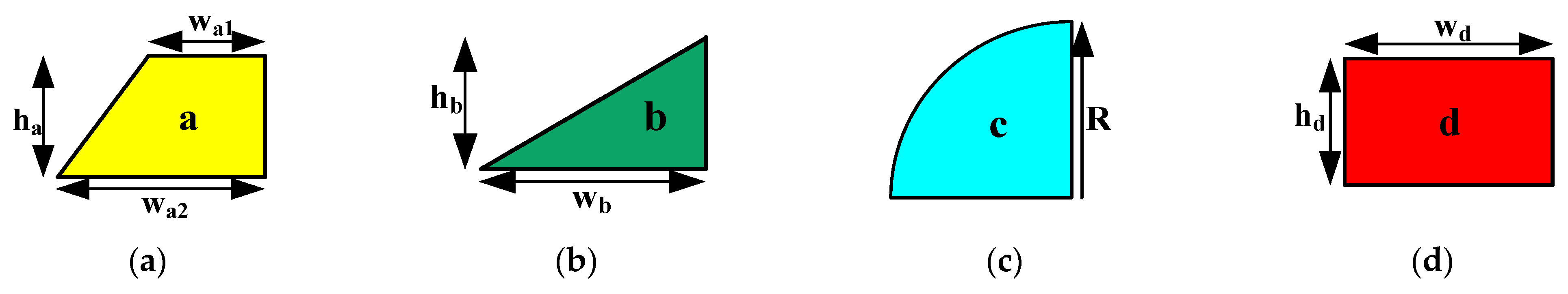
2.1. Permeance Sample

When creating the MEC of a linear PM motor, four different permeance form types must be considered. Figure 3 depicts these four various types of permeance. Equations (1)–(8) can be used to calculate permeances in Figure 3 [5].
P x a = μ a L a l n ( w a 1 / w a 2 ) h a l n ( w a 1 w a 2 )
P y a = μ a L a h a ( w a 1 w a 2 ) l n ( w a 1 / w a 2 )
P x b = 2 μ b L b w b h b
P y b = 2 μ b L b h b w b
P x c = μ c L c R c π R c / 4
P y c = μ c L c R c π R c / 4
P x d = μ d L d h d w d
P y d = μ d L d w d h d
where a, b, c, and d are superscripts for each part. These parts are shown in Figure 3 as a perpendicular trapezoid, triangle, quarter circle, and rectangle, respectively. In addition, the equations indicating the calculation of the permeance of the vertical and horizontal components of these parts are expressed as subscripts. R γ represents the radiuses of the quarter circle particle in Figure 3a. μ and L denote the permeability and effective length of each particle, respectively. Also, heights and widths are denoted by h and w, respectively.

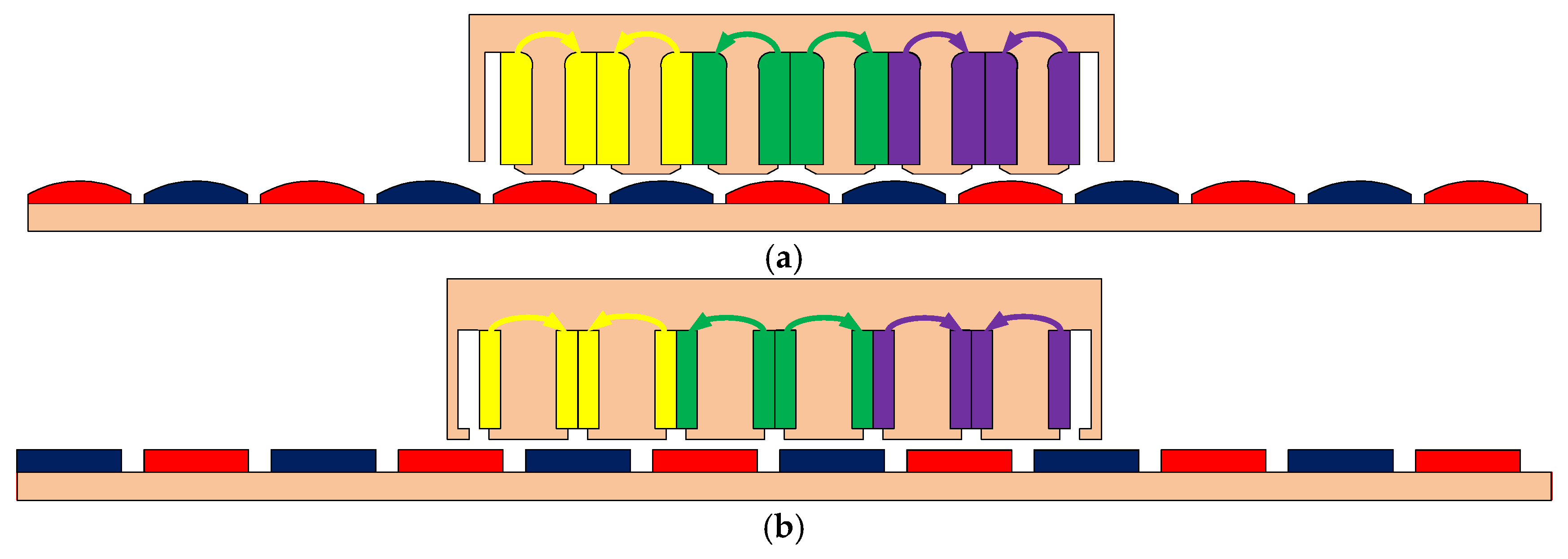
2.2. Air-Gap Modeling

In all electrical motors, the MF must pass through the air-gap between the stator core and rotor core. As a result, accurate modeling of the air-gap is essential in all electrical motors for calculating electromagnetic performance criteria. The MF is transferred from the stator to the air-gap and from there to the rotor, forming its magnetic circuit. Therefore, a large part of electromagnetic energy exchange occurs in the air-gap. Consequently, air-gap modeling poses significant challenges in linear PM motors due to complex magnetic interactions. Because accurate modeling of the air-gap becomes challenging due to the presence of leakage fluxes arising from interactions between the stator teeth and magnets. One of the air-gap modeling methods is the MEC. However, leakage fluxes create problems for the MEC. However, it is proposed to minimize these challenges by modeling the air-gap into small sections to solve these issues.
The horizontal and vertical components of air-gap magnetic field densities are calculated with the same lengths. Some assumptions are considered for these calculations. One of these assumptions is that permeability is considered as a diamond shape. The air-gap permeance in Figure 3 can be computed as (9) and (10):
P x g = μ 0 L i w d w d = μ 0 L i
P y g = μ 0 L i w d w d = μ 0 L i
where L i is the effective length. μ 0 represents vacuum permeability.

2.3. Stator Modeling

Stator’s sectional area, which is the moving part of the linear PM motor, is shown in Figure 2. Considering stator modeling, the stator can be divided into five different areas in terms of permeance. These areas are the stator yoke, stator tooth, stator tooth tip, slot, and slot opening. Permeances should be modeled separately. Figure 4 shows stator modeling. Horizontal and vertical permeances are shown in red and blue, respectively. The yellow color indicates linear permeance, while the green color indicates non-linear permeance. The windings generate magnetomotive force (MMF). And their calculation is presented in Section 3.2. Permeances on the stator side can be calculated as in (11)–(15).
P x s y = μ 0 L i w s N s l s
P x s = μ 0 L i h s t t w s t / 2
P y s = μ 0 L i w s t / 2 h s t t
P y s t = μ 0 L i w t h h s t t / 2
P x s t t = μ 0 L i w t s p w s t t / 2
P x s y , P x s , P y s , P y s t , and P x s t t denote stator yoke permeance, stator slot horizontal permeance, stator slot vertical permeance, and stator tooth tip permeance, respectively. N s is the number of stator teeth. Also h s t t , w s t , w s , h s t t , w t s p , and w s t t are stator tooth thickness, stator slot width, stator yoke width, stator tooth tip thickness, and stator tooth tip width, respectively.

2.4. Magnetic Source Modeling

The magnetic source in PM electrical motors consists of two different types. One of these sources is stator windings. Another is PMs, which are a flux source. But the flux source and MMF can be converted to each other, according to the Thevenin and Norton equivalent circuit. The relative and recoil permeabilities will be assumed to be roughly constant throughout this study. The permeance, MMF, and flux of PMs can be characterized as in (16)–(18):
Ψ p m = B r A p m
P p m = A p m μ c μ 0 h p m
P p m Ξ m = Ψ p m
where Ξ m is the PM’s MMF. B r is remanent MF density. μ c denotes the recoil permeability of the PM. The thickness and area of the PM are h p m and A p m , respectively. Figure 4 depicts the CS form of the flux sources and PM.
In general, stator windings in electrical motors have two different winding types: distributed and concentrated winding. Stator windings, which are another magnetic source, can also be modeled as magneto motor force. If it is assumed that the core permeability of these stator windings is infinite, the magnetic field formed by passing current through the coil is called Ampere’s law.
Ξ w = l H · d l = N I
where Ξ w represents the magneto motor force source of the stator winding. N and I show the number of turns and instantaneous stator current, respectively.

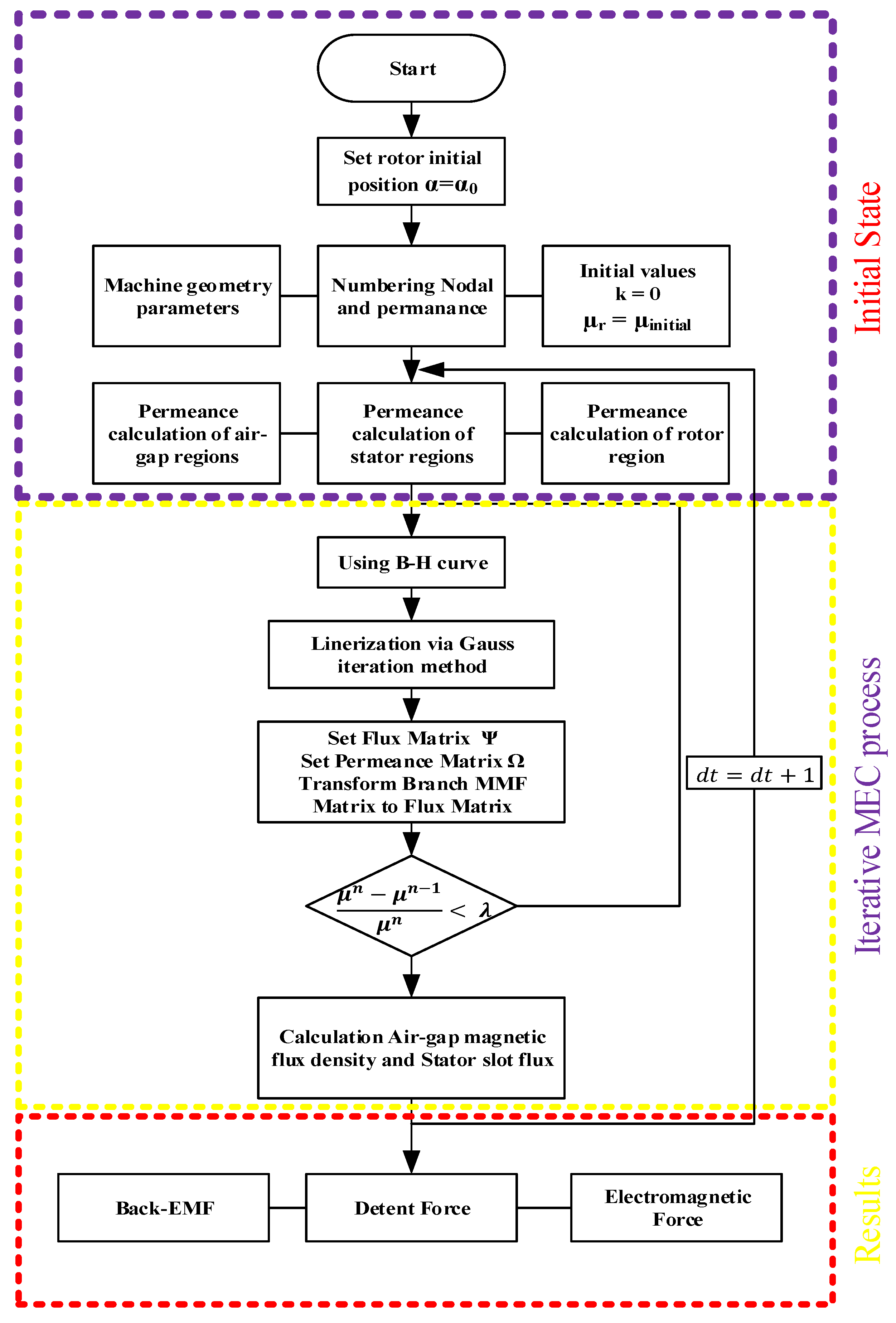
2.5. Iterative MEC Technique

There are several key techniques for electrical circuit analysis. These methods are Kirchoff’s voltage and current law. These are also applicable for analysis of the MEC. The flow diagram shown in Figure 5 shows the iterative resolution of the BH curve characteristic in the MEC. First, it is necessary to create a permeance matrix. The first step to create the permeance matrix is to include constant permeability in the matrix. Then, stator windings and PM MMFs are placed in the MMF matrix. Afterward, the initial permeability of magnetic steel is determined to start the iteration, and this value is set to 100. After initialization, another step is to place permeance into the permeance matrix. The permeance and flux matrix are determined with an iteration process. After these determined matrix processes, the node MMFs matrix can be calculated easily in (20).
Ξ 1 Ξ 2 Ξ i = P 1,1 P 1,2 P 1 , j P 2,1 P i , 1 P 2,2 P i , 2 P 2 , j P i , j 1 Ψ 1 Ψ 2 Ψ i
The matrix can also be represented as in (21).
Ξ = P 1 Ψ
where t represents the number of nodes in the MEC. [P−1] is the state in which it is sequentially placed in the matrix. The representation of the MMF node as a matrix is [ Ξ ]. The matrix G is indicated by a symmetric matrix, while the series of the MF source is also [ Ψ ]. The rules must be followed for the permeability matrix’s notations in (22).
P i , j = P j , i P i , j = P j , i < 0 P i , j = P j , i > 0 i j i j i = j
The above equations need to be linearized. Consequently, the advanced Gaussian Iteration Method (GIM) is the technique adopted. The GIM is summarized as in (23).
Ξ k + 1 = ϖ ξ η 1 1 ξ ϖ + ξ ν Ξ k + ξ ϖ ξ η 1 Ψ k
where k is the number of iterations and ξ is the relaxation factor, which ranges from zero to two.
Λ = ϖ η ν ϖ i , j = Λ i , j i = j 0 i j η i , j = Λ i , j i > j 0 i j ν i , j = Λ i , j i < j 0 i j
After (24), non-linearity becomes a linear problem. Node MMFs can be calculated after this process. After the GIM’s process, MF density on any permeance can be calculated. The flux and MF density on the permeance can be expressed as in (25) and (26).
Ψ i , j = Ξ i Ξ j P i , j
B i , j = Ψ i , j A i , j
where Ψ i , j stands for the MF of the permeance between the adjacent node. B i , j denotes the MF density of the permeance. The cross-sectional area of the permeance is represented by the notation A i , j . The BH curve is used to determine the permeability of the magnetic core. In this curve, the permeability value is reached by applying the interpolation method. Also, n, the magnetic permeability of the element, needs to be linearized. The formulation of this situation can be shown as in (27).
H ( k ) n = H ( k ) + ( B ( k ) n B ( n 1 ) ) ( H n 1 H ( n ) ) ( B n 1 B ( n ) )
where the values of B n 1 and B n signify the point of the BH curve above and below the value of B k n , respectively. The values of H n 1 and H n stand for the BH curve values above and below the value of H k n , respectively. Linerization is indicated by the symbol μ k n . The following is a solution to the magnetic permeability iteration equation:
μ n μ n 1 μ n < ε
Here, it consists of iterations at the values μ n and μ n 1 . Also, ε represents the erroneous magnetic permeability and is set to 0.001.
B r , s = B r , 0 1 + β ( T p m T 0 )
where B r , s and B r , 0 represent the PM magnetic flux density at the actual rotor temperature T p m and the reference temperature T 0 , respectively. The parameter β denotes the temperature coefficient.

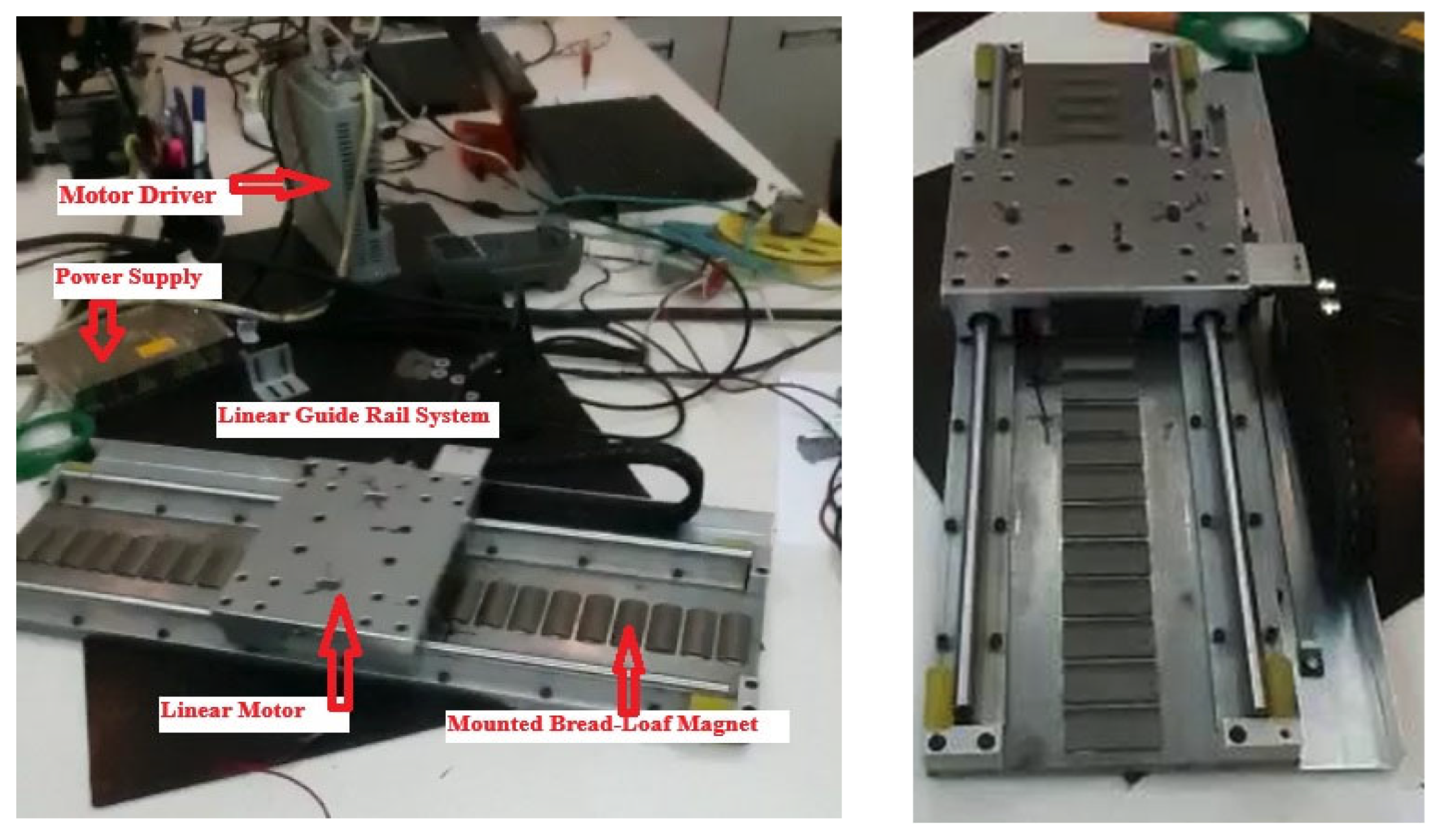
3. FEA and Experimental Validation

In this chapter, the electromagnetic distributions of the linear PM machine, such as the flux distribution, cogging force, back-EMF, and total force are calculated using the proposed MEC. FEA is widely regarded as one of the most accurate and comprehensive techniques for analyzing the electromagnetic behavior of electrical machines. Meshing constitutes a fundamental step in the finite element analysis (FEA) process. Meshing is discretization of an electrical motor into elements suitable for FEA. Therefore, employing a properly refined mesh enables simulation results that closely align with experimental data. In Figure 6, the linear PM motors are depicted as being suitably mesh. Furthermore, Figure 7 provides the linear PM motor’s MF distribution. Additionally, Figure 8 depicts the MF distribution of linear PM motors. The non-linear BH curve of the steel core is shown in Figure 9. Linear PM motors have been analyzed in the ANSYS-Maxwell 2023 R2 application using FEA. These results are used to validate the accuracy and effectiveness of the proposed MEC model. The MEC model provides results that closely match those of FEA, while requiring significantly less computational time. Table 3 shows a comparison between FEA and the proposed MEC in terms of time.
The experimental setup consists of a bread-loaf type linear PM motor mounted on a linear guide rail system (Figure 10). A programmable current source provides excitation to the motor windings, and a motor driver controls the system. A power supply feeds the setup, while a computer is used to record measurements via a data acquisition system. This configuration is used to validate the performance of the proposed motor model under controlled conditions.
The environment was maintained at 25 ± 2 °C. Measurement uncertainties were evaluated based on sensor specifications and multiple test repetitions, resulting in a maximum error margin of approximately 2–3%.

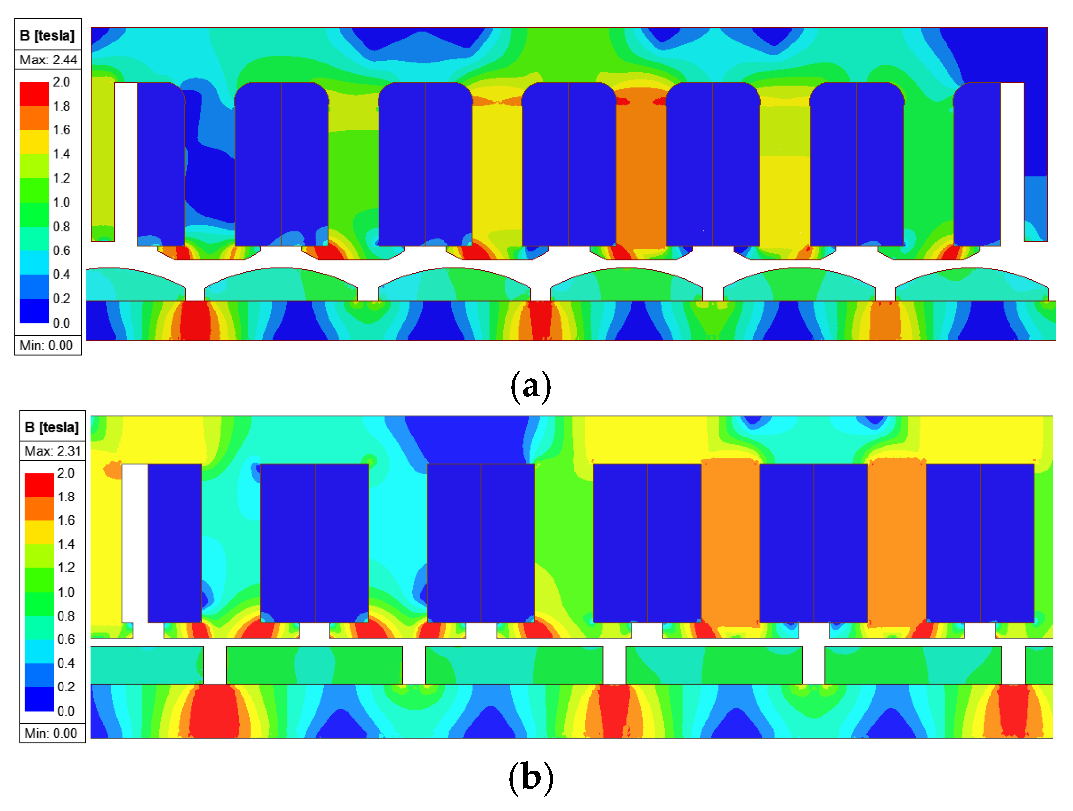
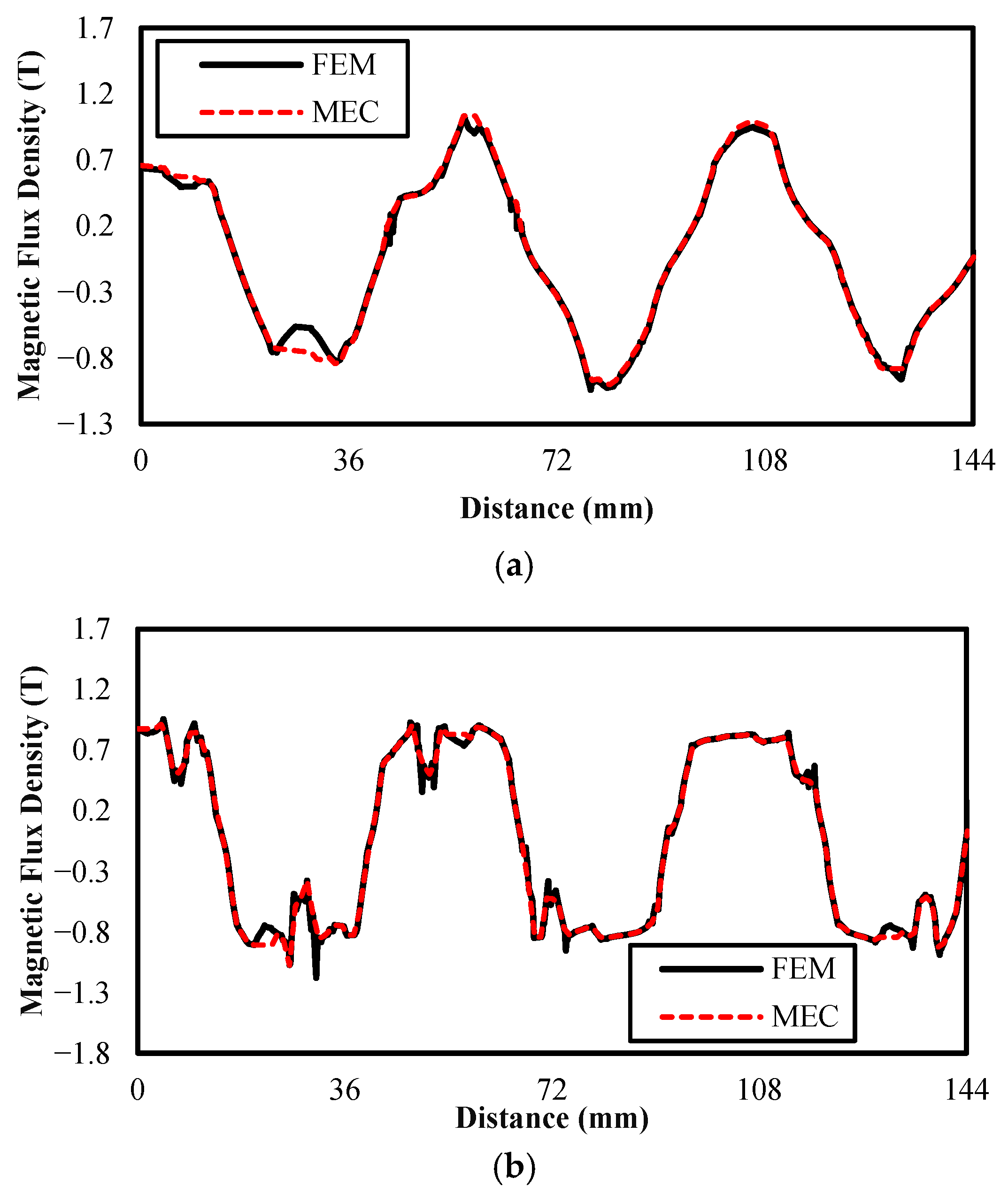
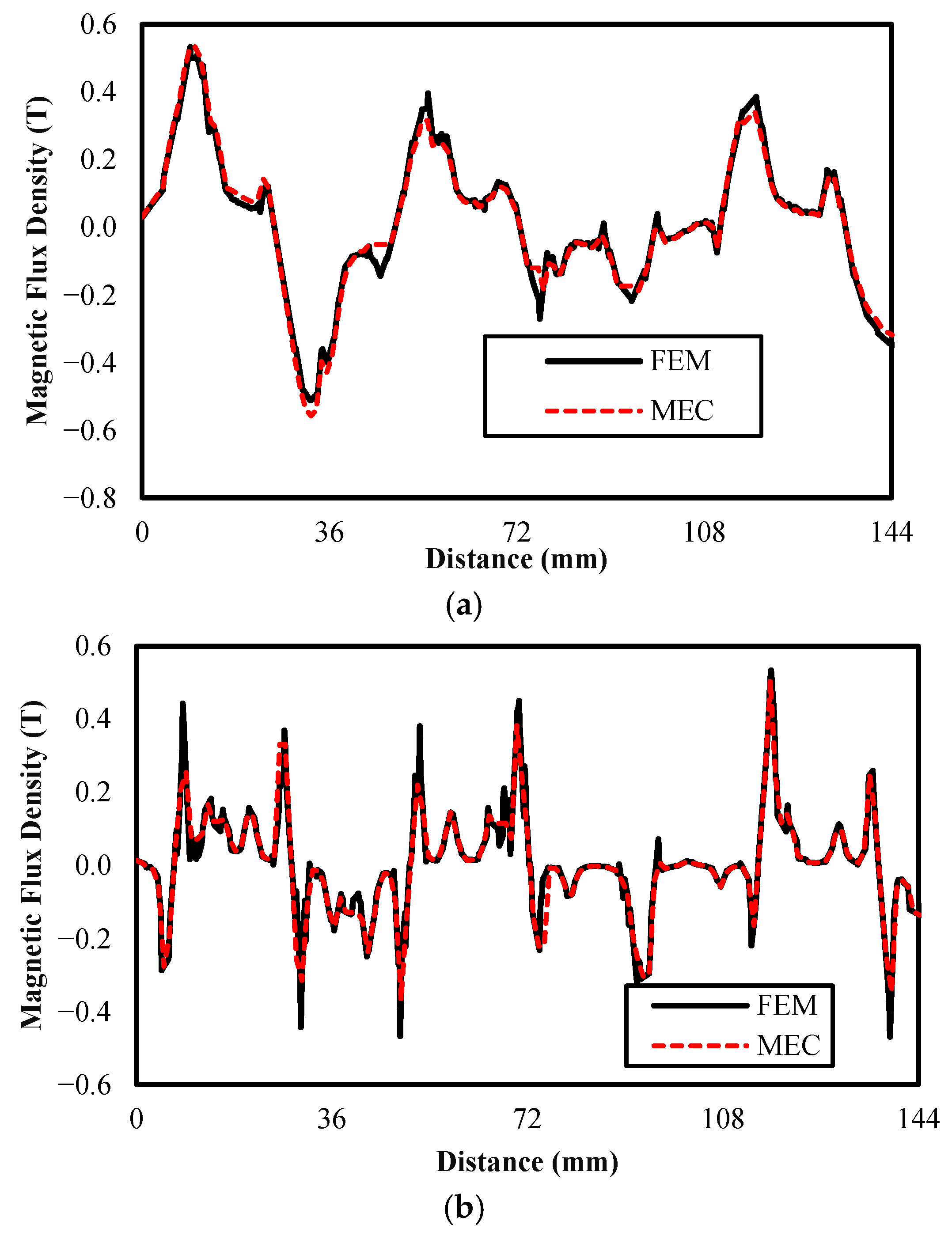
3.1. Air-Gap MF Density
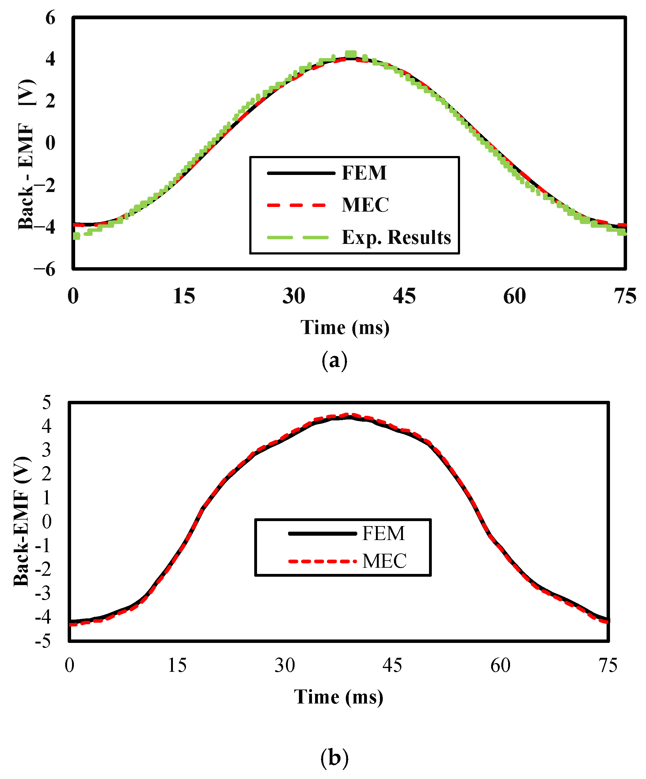
Air-gap magnetic flux density plays a critical role in determining key performance metrics of electrical machines. For this reason, many different numerical and analytical methods have been presented to calculate air-gap MF density. The proposed air-gap model in Figure 4 is used to analyze air-gap MF density. It is an important detail to calculate the vertical component of air-gap MF density by dividing the area of the flux passing through the permeance shown in red into small pieces, while the horizontal component of air-gap MF density is calculated by dividing the area of the flux passing through the permeance shown in green into small pieces.
The air-gap flux distributions evaluated by FEA and MEC for the no-load condition are shown in Figure 11 and Figure 12. The analytical result revealed similar values to FEA as shown in Figure 11 and Figure 12. A notable level of magnetic saturation is observed under no-load conditions as indicated by the flux density distribution. However, the computed error rate is quantitatively low, indicating a strong agreement between the compared methods. In summary, the results obtained from the MEC model closely align with those generated by FEA. In this article, the MEC demonstrates accurate modeling for the air-gap domain and high-accuracy results. It has been shown that accurate results can be obtained via the MEC as well as FEA.

3.2. Back-EMF

The flux linkage ψ c generated by a single turn coil is in (30).
Ψ c ( t ) = L i τ c 2 + τ c 2 B y ( x , y , t ) d x
where the coil span angle is represented by τ c . The mechanical differantial is expressed by d x , and the normal element of MF density at the surface of the stator is designated by B y ( x , y , t ) . Predicting the back-electromotive force (back-EMF) can be achieved with good accuracy using the normal component of MF density. Nevertheless, obtaining perfectly accurate results is not feasible due to the inherent limitations of the analytical model. The leakage flux throughout a slot and at the surfaces of the tooth tips is examined using permeance in the MEC. And its calculations can be as in (31) and (32).
Ψ l e a k ( t ) = L i h s t h s y w s t / 2 + w s t / 2 B x ( x , y , t ) d x d y
Ψ l e a k t = Ψ l e a k l t + Ψ l e a k r t = n ɸ ( Ψ l e a k l t + Ψ l e a k r t )
where h s y and h s t are stator yoke height and stator slot opening height, respectively. B x ( x , y , t ) represents vertical MF density in the stator tooth. In terms of mechanical distance, the stator slot’s width is represented by w s t . After (27)–(30), the overall flux flowing through winding can be defined in (33) [4].
Ψ p h t = N p h ( Ψ c t + Ψ l e a k l t + Ψ l e a k r t )
where N p h represents the phase’s turn number. MF leakage where a coil joins and leaves the stator slots is referred to as Ψ l e a k l t and Ψ l e a k r t , respectively. In accordance with Lenz and Faraday’s laws, it calculates the negative value of the induced voltage by taking the derivative of the flux generated from the coil and multiplying it by the number of turns of coil.
E p h t = N p h d Ψ p h t d t
E p h t represents the back-EMF value in a single phase in the no-load state. Figure 12 displays the difference between the back-EMF of any phase calculated by FEA and the MEC. As illustrated in Figure 13, the results obtained from the MEC closely correspond to those produced by FEA.

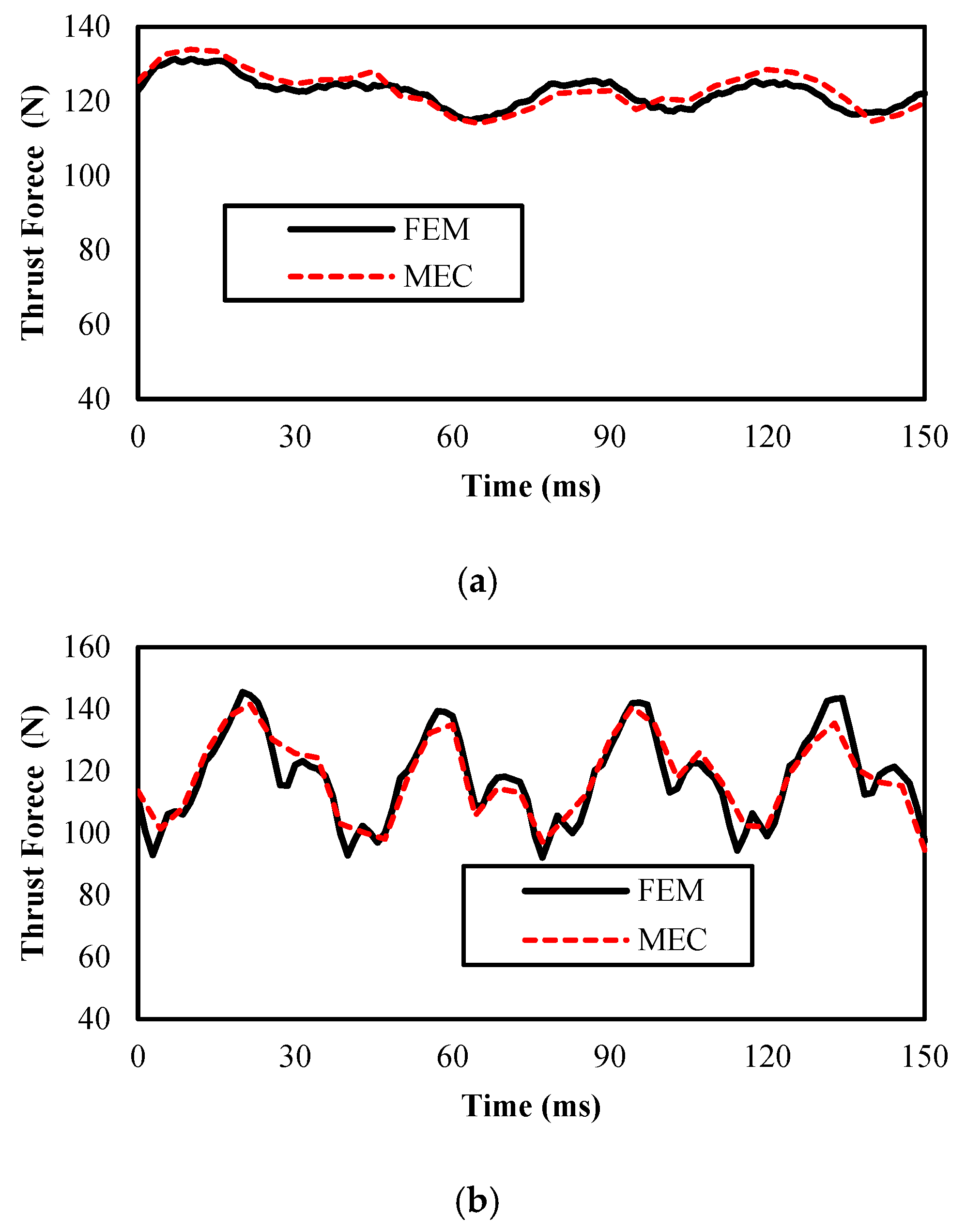
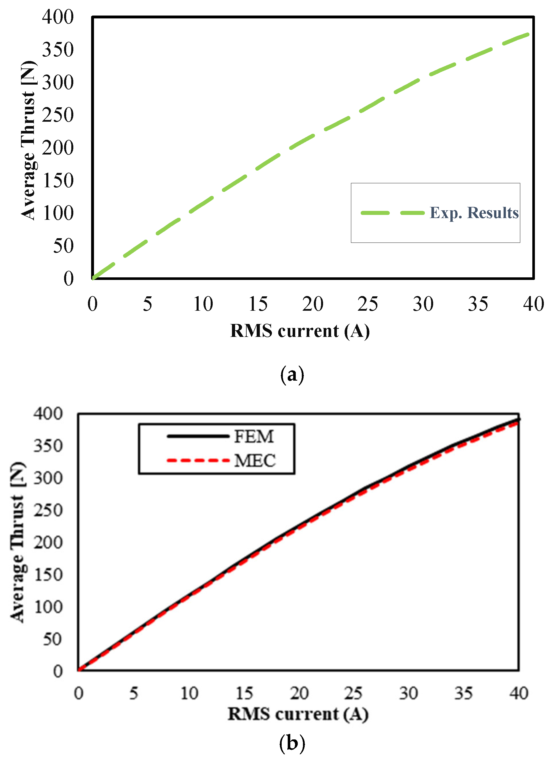
3.3. Electromagnetic and Detent Force

The horizontal electromagnetic thrust of the linear PM motor is analyzed and calculated by using the magnetic field as a foundation; the Maxwell Stress Tensor (MST) is used. To calculate the electromagnetic force that each stressed area of the object experiences in respect to the tension on the surface outside of the item’s area, an equal density of the magnetic field tension tensor must be integrated. From there, the electromagnetic force sum is determined. Because of the magnetic interactions between the magnets and the stator’s windings, the electromagnetic force is created. The net electromagnetic force generated along the motor’s axis is defined as the thrust force. Additionally, thrust force is generated as a result of electromagnetic interaction even in the absence of current in the windings. This force is generated in the absence of stator current due to the magnetic interaction between the permanent magnets and the stator teeth. The PM and stator teeth come in contact magnetically, causing the force. 2-D–estimated MF density can be used for Maxwell’s equation to obtain the total electromagnetic thrust as in (35).
F = L i μ 0 p [ B ( | B · n ) 0.5 · B 2 n ] d p
The following are the expressions for B and n :
n = n x a x + n y a y B = B x a x + B y a y
Unit vectors in the x and y directions are a x and a y . The normal vectors of the surface are projected in the x and y directions as n x and n y .
The motor’s electromagnetic force magnitudes, both horizontally and normally, are as in (37) and (38)
F x = L i μ 0 p ( B x 2 B y 2 ) n x + 2 B x B y n y d p
F y = L i μ 0 p ( B y 2 B x 2 ) n y + 2 B x B y n x d p
This equation emphasizes the horizontal electromagnetic thrust, where B x and B y are normal and tangential MF densities, and the integral path is p. Figure 14, Figure 15 and Figure 16 show detent force, thrust force, and average thrust force for linear PM motors, respectively.

4. Conclusions

This study has proposed an improved two-dimensional Magnetic Equivalent Circuit (MEC) model for bread-loaf type linear permanent magnet (PM) motors, addressing several critical challenges in existing analytical models. Specifically, electromagnetic performances were predicted by considering the non-linear BH curve of the magnetic core; winding leakage fluxes were incorporated into the back-EMF calculation, and the electromagnetic force was accurately determined using the Maxwell Stress Tensor by including the tangential magnetic flux density in the air-gap. The proposed model was experimentally validated and demonstrated high accuracy across different operating conditions. Compared to finite element analysis (FEA), it significantly reduces computation time while maintaining comparable precision, making it a practical tool for early-stage motor design and rapid optimization processes.
The model uses the Gaussian Iteration Method (GIM) to effectively handle the non-linear characteristics of the BH curve. Predictions of back-electromotive force (back-EMF) and electromagnetic thrust force using this MEC approach showed strong agreement with FEA results, indicating its capability to capture key electromagnetic behaviors. Moreover, winding leakage was considered for more accurate back-EMF estimations, and electromagnetic force was calculated using the Maxwell Stress Tensor (MST), aligning well with ANSYS–based simulations.
In addition to its validated accuracy, the proposed MEC model offers practical benefits for engineering applications. Due to its low computational complexity, the model is particularly well-suited for early-stage motor design, rapid prototyping, and iterative optimization workflows. The model can be integrated into multi-objective optimization workflows—such as thrust ripple reduction and force density maximization—when combined with intelligent optimization algorithms like genetic algorithms or surrogate models.
In practical scenarios, this approach could significantly reduce simulation time while maintaining sufficient precision, making it valuable for electric vehicle drive modules, high-precision industrial actuators, and robotic automation systems. For example, in electric vehicle linear actuators or CNC positioning systems, the ability to swiftly evaluate design alternatives without resorting to full FEA each time represents a critical benefit in terms of cost and time.
However, certain limitations of the proposed model should also be acknowledged. The MEC approach relies on accurate estimation of magnetic flux paths, which can be challenging for highly asymmetric or unconventional geometries. Additionally, while the model performs well under no-load and steady-state conditions, its extension to dynamic or transient behaviors such as start-up or fault analysis has not been investigated in this study. Future work could focus on improving the adaptability of the model to time-varying excitations and validating its use in more complex system-level simulations.
In conclusion, the improved MEC model offers both high-fidelity electromagnetic modeling and strong engineering applicability. The model offers a balanced trade-off between analytical accuracy and practical applicability, serving as a practical and scalable tool for the design and optimization of advanced linear PM motors.

Author Contributions

Conceptualization, T.S. and Y.Ö.; Methodology, F.T.; Validation, S.A. and F.M.; Formal analysis, Y.Ö.; Investigation, F.T. and T.S.; Resources, Y.Ö.; Writing—original draft, F.T. and T.S.; Writing—review & editing, S.A. and F.M.; Visualization, S.A.; Supervision, Y.Ö. and F.M. All authors have read and agreed to the published version of the manuscript.

Funding

The authors acknowledge the support of the project “Development and optimization of a high-efficiency sea wave electrical power generator”, CUP H53D23007410001, project P2022SY7LH, financed by EU in NextGenerationEU plan through the Ministry of University and Research (MUR) within the framework of the PRIN 2022 PNRR “Scientific Research Programmes of Outstanding National Interest”.

Data Availability Statement

The original contributions presented in this study are included in the article. Further inquiries can be directed to the corresponding author(s).

Conflicts of Interest

The authors declare no conflict of interest.

References

  1. Rahideh, A.; Ghaffari, A.; Barzegar, A.; Mahmoudi, A. Analytical model of slotless brushless PM linear motors considering different magnetization patterns. IEEE Trans. Energy Convers. 2018, 33, 1797–1804. [Google Scholar] [CrossRef]
  2. Hu, H.; Zhao, J.; Liu, X.; Guo, Y. Magnetic Field and Force Calculation in Linear Permanent-Magnet Synchronous Machines Accounting for Longitudinal End Effect. IEEE Trans. Ind. Electron. 2016, 63, 7632–7643. [Google Scholar] [CrossRef]
  3. Wu, T.; Feng, Z.; Wu, C.; Lei, G.; Guo, Y.; Zhu, J.; Wang, X. Multiobjective Optimization of a Tubular Coreless LPMSM Based on Adaptive Multiobjective Black Hole Algorithm. IEEE Trans. Ind. Electron. 2020, 67, 3901–3910. [Google Scholar] [CrossRef]
  4. Sapmaz, T.; Oner, Y. Improved magnetic equivalent circuit for dual stator consequent pole permanent magnet machine. J. Magn. Magn. Mater. 2022, 550, 169039. [Google Scholar] [CrossRef]
  5. Solak, B.; Sapmaz, T.; Oner, Y. Non-linear analytical model for synchronous reluctance machine. J. Magn. Magn. Mater. 2023, 571, 170570. [Google Scholar] [CrossRef]
  6. Sapmaz, T.; Oner, Y. A novel hybrid model of electromagnetic performance for induction machine. Electr. Eng. 2022, 104, 3381–3390. [Google Scholar] [CrossRef]
  7. Sun, X.; Shi, Z.; Cai, Y.; Lei, G.; Guo, Y.; Zhu, J. Driving-Cycle-Oriented Design Optimization of a Permanent Magnet Hub Motor Drive System for a Four-Wheel-Drive Electric Vehicle. Trans. Transp. Electrif. 2020, 6, 1115–1125. [Google Scholar] [CrossRef]
  8. Sun, X.; Xu, N.; Yao, M. Sequential Subspace Optimization Design of a Dual Three-Phase Permanent Magnet Synchronous Hub Motor Based on NSGA III. IEEE Trans. Transp. Electrif. 2023, 9, 622–630. [Google Scholar] [CrossRef]
  9. Jin, Z.; Sun, X.; Chen, L.; Yang, Z. Robust Multi-Objective Optimization of a 3-Pole Active Magnetic Bearing Based on Combined Curves with Climbing Algorithm. IEEE Trans. Ind. Electron. 2022, 69, 5491–5501. [Google Scholar] [CrossRef]
  10. Hu, H.; Liu, X.; Zhao, J.; Guo, Y. Analysis and minimization of detent end force in linear permanent magnet synchronous machines. IEEE Trans. Ind. Electron. 2018, 65, 2475–2486. [Google Scholar] [CrossRef]
  11. Ghaffari, A.; Rahideh, A.; Ghaffari, H.; Vahaj, A.; Mahmoudi, A. Comparison between 2-D and 0-D analytical models for slotless double-sided inner armature linear permanent magnet synchronous machines. Int. Trans. Electr. Energy Syst. 2020, 30, e12509. [Google Scholar] [CrossRef]
  12. Guo, R.; Yu, H.; Xia, T.; Shi, Z.; Zhong, W.; Liu, X. A Simplified Subdomain Analytical Model for the Design and Analysis of a Tubular Linear Permanent Magnet Oscillation Generator. IEEE Access 2018, 6, 42355–42367. [Google Scholar] [CrossRef]
  13. Amini, S.; Faiz, J. Performance analysis of linear permanent magnet Vernier machine using mixed subdomain and magnetic equivalent circuit techniques including end-effect. IET Electr. Power Appl. 2022, 16, 966–984. [Google Scholar] [CrossRef]
  14. Zhou, Y.; Wu, X. Analytical calculation of magnetic field of bearingless flux-switching permanent-magnet machine based on doubly-salient relative permeance method. IET Electr. Power Appl. 2020, 14, 872–884. [Google Scholar] [CrossRef]
  15. Devillers, E.; Le Besnerais, J.; Lubin, T.; Hecquet, M.; Lecointe, J.P. An Improved 2-D Subdomain Model of Squirrel-Cage Induction Machine Including Winding and Slotting Harmonics at Steady State. IEEE Trans. Magn. 2018, 54, 2. [Google Scholar] [CrossRef]
  16. Roshandel, E.; Mahmoudi, A.; Kahourzade, S.; Soong, W.L. Saturation Consideration in Modeling of the Induction Machine Using Subdomain Technique to Predict Performance. IEEE Trans. Ind. Appl. 2022, 58, 261–272. [Google Scholar] [CrossRef]
  17. Pourahmadi-Nakhli, M.; Rahideh, A.; Mardaneh, M. Analytical 2-D model of slotted brushless machines with cubic spoke-Type permanent magnets. IEEE Trans. Energy Convers. 2018, 33, 373–382. [Google Scholar] [CrossRef]
  18. Zhu, M.; Zeng, P.; Lou, X.; Mao, G.; Dou, Y.; He, Z. Analytical model of a dual-stator spoke-type permanent magnet synchronous machines accounting for tooth-tips. IET Electr. Power Appl. 2022, 16, 1117–1134. [Google Scholar] [CrossRef]
  19. Faradonbeh, V.Z.; Rahideh, A.; Markadeh, G.A. Analytical model for slotted stator brushless surface inset permanent magnet machines using virtual current theory. IET Electr. Power Appl. 2020, 14, 2750–2761. [Google Scholar] [CrossRef]
  20. Wu, L.J.; Zhu, Z.Q.; Staton, D.; Popescu, M.; Hawkins, D. Analytical prediction of electromagnetic performance of surface-mounted PM machines based on subdomain model accounting for tooth-tips. IET Electr. Power Appl. 2011, 5, 597–609. [Google Scholar] [CrossRef]
  21. Ghahfarokhi, M.M.; Faradonbeh, V.Z.; Amiri, E.; Bafrouei, S.M.M.; Aliabad, A.D.; Boroujeni, S.T. Computationally Efficient Analytical Model of Interior Permanent Magnet Machines Considering Stator Slotting Effects. IEEE Trans. Ind. Appl. 2022, 58, 4587–4601. [Google Scholar] [CrossRef]
  22. Chen, C.; Wu, X.; Yuan, X.; Ding, Z.; Zheng, X. Hybrid analytical model for air-gap magnetic field prediction of surface-mounted permanent magnet motors with a quasi-regular polygon rotor. IET Electr. Power Appl. 2023, 17, 1136–1147. [Google Scholar] [CrossRef]
  23. Wang, W.; Cheng, M. Analytical model of a fractional slot double-layer-winding vernier permanent magnet machine. IET Electr. Power Appl. 2023, 17, 293–305. [Google Scholar] [CrossRef]
  24. Vahaj, A.A.; Rahideh, A.; Zamani Faradonbeh, V.; Salehi, A.R.; Ghaffari, A.; Shahnazari, M.; Lubin, T. 2-D analytical magnetic model for optimal design of an outer rotor permanent magnet synchronous machine. IET Electr. Power Appl. 2023, 17, 1–13. [Google Scholar] [CrossRef]
  25. Hu, H.; Zhao, J.; Liu, X.; Guo, Y.; Zhu, J. No-Load Magnetic Field and Cogging Force Calculation in Linear Permanent-Magnet Synchronous Machines with Semiclosed Slots. IEEE Trans. Ind. Electron. 2017, 64, 5564–5575. [Google Scholar] [CrossRef]
  26. Zhang, H.; Yang, M.; Zhang, Y.; Tuo, J.; Luo, S.; Xu, J. Analytical field model of segmented Halbach array permanent magnet machines considering iron nonlinearity. IET Electr. Power Appl. 2021, 15, 717–727. [Google Scholar] [CrossRef]
  27. Guo, B.; Du, Y.; Peng, F.; Huang, Y. Magnetic Field Calculation in Axial Flux Permanent Magnet Motor with Rotor Eccentricity. IEEE Trans. Magn. 2022, 58, 9. [Google Scholar] [CrossRef]
  28. Ilhan, E.; Motoasca, E.T.; Paulides, J.J.; Lomonova, E.A. Conformal mapping: Schwarz-Christoffel method for flux-switching PM machines. Math. Sci. 2012, 6, 37. [Google Scholar] [CrossRef]
  29. Xue, L.; Luo, L. Semi-Analytical Calculation of the Unsaturated Magnetic Field Distribution of a Slotted Spoke-Type Interior Permanent Magnet Machine with Conformal Mapping Method. IEEE Trans. Magn. 2022, 58, 5. [Google Scholar] [CrossRef]
  30. Zhou, Y.; Xue, Z. Analytical Method for Calculating the Magnetic Field of Spoke-Type Permanent Magnet Machines Accounting for Eccentric Magnetic Pole. IEEE Trans. Ind. Electron. 2021, 68, 2096–2107. [Google Scholar] [CrossRef]
  31. Boughrara, K.; Zarko, D.; Ibtiouen, R.; Touhami, O.; Rezzoug, A. Magnetic field analysis of inset and surface-mounted permanent-magnet synchronous motors using schwarz-christoffel transformation. IEEE Trans. Magn. 2009, 45, 3166–3178. [Google Scholar] [CrossRef]
  32. Ma, Y.; Wang, J.; Xiao, Y.; Zhou, L.; Kang, H. Transfer learning-based surrogate-assisted design optimisation of a five-phase magnet-shaping PMSM. IET Electr. Power Appl. 2021, 15, 1281–1299. [Google Scholar] [CrossRef]
  33. Mirahki, H.; Moallem, M.; Ebrahimi, M.; Fahimi, B. Combined ON/OFF and conformal mapping method for magnet shape optimisation of SPMSM. IET Electr. Power Appl. 2018, 12, 1365–1370. [Google Scholar] [CrossRef]
  34. Ramakrishnan, K.; Zarko, D.; Hanic, A.; Mastinu, G. Improved method for field analysis of surface permanent magnet machines using Schwarz-Christoffel transformation. IET Electr. Power Appl. 2017, 11, 1067–1075. [Google Scholar] [CrossRef]
  35. Ramakrishnan, K.; Curti, M.; Zarko, D.; Mastinu, G.; Paulides, J.J.H.; Lomonova, E.A. Comparative analysis of various methods for modelling surface permanent magnet machines. IET Electr. Power Appl. 2017, 11, 540–547. [Google Scholar] [CrossRef]
  36. Taravat, S.; Kiyoumarsi, A.; Bracikowski, N. Mitigation of cogging torque in TFPM machines with flux concentrators and evaluation of the structures by using the SC method. IET Electr. Power Appl. 2020, 14, 552–560. [Google Scholar] [CrossRef]
  37. Anglada, J.R.; Sharkh, S.M. Analytical calculation of the torque produced by transverse flux machines. IET Electr. Power Appl. 2017, 11, 1298–1305. [Google Scholar] [CrossRef]
  38. Tessarolo, A. Modeling and analysis of synchronous reluctance machines with circular flux barriers through conformal mapping. IEEE Trans. Magn. 2015, 51, 4. [Google Scholar] [CrossRef]
  39. Ayat, Y.S.; Pahlavani, M.R.A. 3D computation of no-load magnetic flux density in slotless axial-flux permanent-magnet synchronous machines using conformal mapping. IET Electr. Power Appl. 2017, 11, 1391–1396. [Google Scholar] [CrossRef]
  40. Guo, R.; Zhang, F.; Guo, B. Modelling and Research on a Laminated Tubular Linear Oscillating Generator for Free-piston Stirling Energy Conversion. IEEE Trans. Magn. 2022, 58, 9. [Google Scholar] [CrossRef]
  41. Zhao, Y.; Li, Y.; Lu, Q. An Accurate No-Load Analytical Model of Flat Linear Permanent Magnet Synchronous Machine Accounting for End Effects. IEEE Trans. Magn. 2023, 59, 1. [Google Scholar] [CrossRef]
  42. Naderi, P.; Heidary, M.; Vahedi, M. Performance analysis of ladder-secondary-linear induction motor with two different secondary types using Magnetic Equivalent Circuit. ISA Trans. 2020, 103, 355–365. [Google Scholar] [CrossRef] [PubMed]
  43. Jun, C.S.; Kwon, O.; Kwon, B., II. Sensitivity Comparison of Open-Circuit Airgap Flux between Surface-Mounted Permanent Magnet and Spoke-Type Permanent Magnet Machines Considering Manufacturing Tolerances. IEEE Access 2019, 7, 165908–165918. [Google Scholar] [CrossRef]
  44. Faradonbeh, V.Z.; Rahideh, A. 2-D analytical on-load electromagnetic model for double-layer slotted interior permanent magnet synchronous machines. IET Electr. Power Appl. 2022, 16, 394–406. [Google Scholar] [CrossRef]
  45. Luo, C.; Sun, J. Semi-interior permanent-magnet actuators for high-magnet-utilisation and low-cost applications. IET Electr. Power Appl. 2019, 13, 223–229. [Google Scholar] [CrossRef]
  46. Ilka, R.; Alinejad-Beromi, Y.; Yaghobi, H. Techno-economic design optimisation of an interior permanent-magnet synchronous motor by the multi-objective approach. IET Electr. Power Appl. 2018, 12, 972–978. [Google Scholar] [CrossRef]
  47. Mohammadi, S.; Mirsalim, M. Double-sided permanent-magnet radial-flux eddycurrent couplers: Three-dimensional analytical modelling, static and transient study, and sensitivity analysis. IET Electr. Power Appl. 2013, 7, 665–679. [Google Scholar] [CrossRef]
  48. Naderi, P. Magnetic-equivalent-circuit approach for inter-turn and demagnetisation faults analysis in surface mounted permanent-magnet synchronous machines using pole specific search-coil technique. IET Electr. Power Appl. 2018, 12, 916–928. [Google Scholar] [CrossRef]
  49. Davarpanah, G.; Mohammadi, S.; Lang, J.H.; Kirtley, J.L. Two-phase switched reluctance motor with hybrid excitation: Modeling and evaluation. IET Electr. Power Appl. 2023, 17, 939–951. [Google Scholar] [CrossRef]
  50. Ding, W.; Hu, Y.; Fu, H.; Chen, Q. Analysis and evaluation of modular E-shaped stator switched reluctance machines employing segmented and conventional rotor topologies. IET Electr. Power Appl. 2016, 10, 939–951. [Google Scholar] [CrossRef]
  51. Ghaffarpour, A.; Vatani, M.; Kondelaji, M.A.J.; Mirsalim, M. Analysis of linear permanent magnet switched reluctance motors with modular and segmental movers. IET Electr. Power Appl. 2023, 17, 756–772. [Google Scholar] [CrossRef]
  52. Sharouni, S.; Naderi, P.; Hedayati, M.; Hajihosseini, P. Performance analysis of a novel outer rotor flux-switching permanent magnet machine as motor/generator for vehicular and aircraft applications. IET Electr. Power Appl. 2021, 15, 243–254. [Google Scholar] [CrossRef]
  53. Ajamloo, A.M.; Ghaheri, A.; Shirzad, H.; Afjei, E. Non-linear analytical modelling and optimisation of a 12/8 rotor excited flux-switching machine. IET Electr. Power Appl. 2020, 14, 1592–1603. [Google Scholar] [CrossRef]
  54. Radmanesh, H.; Farmahini Farahani, E. Performance evaluation of a new modular split-tooth permanent magnet-assisted switched reluctance motor. IET Electr. Power Appl. 2023, 17, 441–451. [Google Scholar] [CrossRef]
  55. Nyitrai, A.; Kuczmann, M. Magnetic equivalent circuit and finite element modelling of anisotropic rotor axial flux permanent magnet synchronous motors with fractional slot distributed winding. IET Electr. Power Appl. 2023, 17, 709–720. [Google Scholar] [CrossRef]
  56. Ojaghlu, P.; Vahedi, A.; Totoonchian, F. Magnetic equivalent circuit modelling of ring winding axial flux machine. IET Electr. Power Appl. 2018, 12, 293–300. [Google Scholar] [CrossRef]
  57. Ghaheri, A.; Ajamloo, A.M.; Torkaman, H.; Afjei, E. Design, modelling and optimisation of a slotless axial flux permanent magnet generator for direct-drive wind turbine application. IET Electr. Power Appl. 2020, 14, 1291–1310. [Google Scholar] [CrossRef]
  58. Deshan, K.; Dazhi, W.; Wenhui, L.; Sihan, W.; Zhong, H. Analysis of a novel flux adjustable axial flux permanent magnet eddy current coupler. IET Electr. Power Appl. 2023, 17, 181–194. [Google Scholar] [CrossRef]
  59. Zhang, Y.; Wang, Y.; Gao, S. 3-D magnetic equivalent circuit model for a coreless axial flux permanent-magnet synchronous generator. IET Electr. Power Appl. 2021, 15, 1261–1273. [Google Scholar] [CrossRef]
  60. Gao, H.; Zhang, Z.; Wang, C.; Geng, W.; Liu, Y. Analysis of end effect in ironless stator AFPM machine via MEC model. IET Electr. Power Appl. 2020, 14, 147–156. [Google Scholar] [CrossRef]
  61. Mohammadi, S.; Kirtley, J.; Azari, M.N. Modelling of axial-flux eddy-current couplers. IET Electr. Power Appl. 2020, 14, 1238–1246. [Google Scholar] [CrossRef]
  62. Naderi, P.; Sharouni, S.; Moradzadeh, M. Linear vernier machine wave converter modelling and analysis by MEC. IET Electr. Power Appl. 2020, 14, 751–761. [Google Scholar] [CrossRef]
  63. Krämer, C.; Kugi, A.; Kemmetmüller, W. Modeling of a permanent magnet linear synchronous motor using magnetic equivalent circuits. Mechatronics 2021, 76, 102558. [Google Scholar] [CrossRef]
  64. Niknafs, S.; Shiri, A.; Bagheri, S. Design and optimization of air-cored double-sided linear permanent magnet generators for wave energy conversion. Energy Sci. Eng. 2022, 10, 4481–4495. [Google Scholar] [CrossRef]
  65. Heidary, M.; Naderi, P.; Shiri, A. Modeling and analysis of a multi-segmented linear permanent-magnet synchronous machine using a parametric magnetic equivalent circuit. Electr. Eng. 2022, 104, 705–715. [Google Scholar] [CrossRef]
  66. Sheikh-Ghalavand, B.; Vaez-Zadeh, S.; Hassanpour Isfahani, A. An improved magnetic equivalent circuit model for iron-core linear permanent-magnet synchronous motors. IEEE Trans. Magn. 2010, 46, 112–120. [Google Scholar] [CrossRef]
  67. Ullah, W.; Khan, F.; Sulaiman, E.; Umair, M.; Ullah, N. 2-D analytical modelling of novel consequent pole linear permanent magnet flux switching machine. J. Braz. Soc. Mech. Sci. Eng. 2021, 43, 307. [Google Scholar] [CrossRef]
  68. Zouaghi, M.W.; Souissi, A.; Abdennadher, I.; Masmoudi, A. Position varying MEC-based investigation of the no-load operation of T-LPMSMs. COMPEL Int. J. Comput. Math. Electr. Electron. Eng. 2015, 34, 1687–1702. [Google Scholar] [CrossRef]
  69. Vaez-Zadeh, S.; Isfahani, A.H. Enhanced modeling of linear permanent-magnet synchronous motors. IEEE Trans. Magn. 2007, 43, 33–39. [Google Scholar] [CrossRef]
  70. Souissi, A.; Zouaghi, M.W.; Abdennadher, I.; Masmoudi, A. MEC-based modeling and sizing of a tubular linear PM synchronous machine. IEEE Trans. Ind. Appl. 2015, 51, 2181–2194. [Google Scholar] [CrossRef]
Figure 1. Structure of linear PM motor.
Energies 18 03940 g001
Figure 2. Winding topology of linear PM motors: (a) bread-loaf and (b) surface.
Energies 18 03940 g002
Figure 3. MEC permeances of different geometric regions. (a) Trapezoidal section; (b) Right triangular section; (c) Quarter circular section; (d) Rectangular section.
Energies 18 03940 g003
Figure 4. MEC of linear PM motors: (a) bread-loaf and (b) surface.
Energies 18 03940 g004
Figure 5. Flowchart of MEC analysis.
Energies 18 03940 g005
Figure 6. Meshing of linear PM motors: (a) bread-loaf and (b) surface.
Energies 18 03940 g006
Figure 7. Magnitude MF density of linear PM motors: (a) bread-loaf and (b) surface.
Energies 18 03940 g007
Figure 8. MF distribution of linear PM motors: (a) bread-loaf and (b) surface.
Energies 18 03940 g008
Figure 9. BH curve.
Figure 9. BH curve.
Energies 18 03940 g009
Figure 10. Experimental setup for bread-loaf linear PM motor.
Energies 18 03940 g010
Figure 11. Vertical MF density for linear PM motors; (a) bread-loaf and (b) surface.
Energies 18 03940 g011
Figure 12. Horizontal MF density for linear PM motors; (a) bread-loaf and (b) surface.
Energies 18 03940 g012
Figure 13. Back-EMFs for linear PM motors: (a) bread-loaf and (b) surface.
Energies 18 03940 g013
Figure 14. Detent forces for linear PM motors: (a) bread-loaf and (b) surface.
Energies 18 03940 g014
Figure 15. Thrust forces for linear PM motors: (a) bread-loaf and (b) surface.
Energies 18 03940 g015
Figure 16. Average thrust forces for linear PM motors: (a) bread-loaf and (b) surface.
Energies 18 03940 g016
Table 1. Comparison of methods in the literature.
MethodLiteratureSaturationModeling DifficultyAccuracyFlux Leakage ModelGeometric FlexibilityMST
Subdomain[6,13,14,15,16,17,18,19,20,21,22,23,24,25,26,27]NoEasyHighYesNoYes
Conformal mapping[22,28,29,30,31,32,33,34,35,36,37,38,39]NoEasyMedium/
High
NoNoYes
MEC[42,43,44,45,46,47,48,49,50,51,52,53,54,55,56,57,58,59,60,61,62,63] except for [45]YesDifficultLow/MediumNoYesNo
MEC for linear PM machine[62,63,64,65,66,67,68,69,70]YesModerateMediumNoYesNo
Improved MEC-YesModerateHighYesYesYes
Table 2. Parameters.
Value [Unit]
Item [Symbol]Bread-LoafSurfaceItem [Symbol]Bread-LoafSurface
Rated power100 [W] Stator   yoke   width   [ w s ] 8.26 [mm]6.25 [mm]
Rated speed0.7 [m/s]Stator slot opening width [ w s t t ] 14 [mm]
Number of stator slots [ N s ]7Stator slot width [ w s t ]6.2 [mm]4 [mm]
Number of poles13Stator slot opening height [ h s t ]2.06 [mm]
Number of turns [ N p h ]3550Rotor width [ l r ]338 [mm]
Stator width [ l s ]144 [mm]148 [mm]Stator yoke width [ w r ]6 [mm]7 [mm]
Stator outer height [ h o ]47.25 [mm]42 [mm]PM permeability [ μ c ] 1.051
Stator yoke height [ h s y ]39 [mm]35.75 [mm]Remanence MFD [ B r ] 1.23 [T]1 [T]
Stator tooth height [ h s ]6.25 [mm]13 [mm]PM height max [ h p m m a x ] 5 [mm]
Stator tooth width [ w t h ]7.67 [mm]7.7 [mm]PM height min [ h p m m i x ]2 [mm]5 [mm]
Stator tooth thickness [ h s t t ]24.68 [mm]21 [mm]PM width [ w p m ]23 [mm]
Stator slot opening width [ w s o ]8.31 [mm]4 [mm]Air-gap [ g ]1.25 [mm]1 [mm]
Table 3. Analysis of time comparison of the FEMM and MEC at no-load and on-load.
Analyze TypeMachine TypeMECFEA
No-LoadSurface18461
Bread-Loaf18680
On-LoadSurface25572
Bread-Loaf24644
Disclaimer/Publisher’s Note: The statements, opinions and data contained in all publications are solely those of the individual author(s) and contributor(s) and not of MDPI and/or the editor(s). MDPI and/or the editor(s) disclaim responsibility for any injury to people or property resulting from any ideas, methods, instructions or products referred to in the content.

