1. Introduction
Concern over climatic changes and commitment towards a low-carbon footprint have necessitated integration of renewable energy (RE) technologies into power systems. To address the challenges of variable RE sources, the concept of a smart grid has evolved, which incorporates renewable energy, characterized by high efficiency, automated transmission and distribution systems through advanced sensing measurement and control technologies, self-healing, and responsiveness to the energy market.
The US Department of Energy [
1] defines a microgrid as a group of distributed energy resources and interconnected loads within clearly defined electric boundaries that can act as a single controllable entity, capable of grid-connected and islanded operation and enhanced power availability, and resilient to grid disturbances. Microgrids, as envisioned in [
2,
3], serve as a key building block for affordable smart grids that support resilience and decarbonization. Networked microgrids/multi-microgrids/microgrid clusters are common terminologies used to define the advanced concept of electrical networks interconnected with several adjacent microgrids [
4]. The hierarchical system-of-systems (SoS) framework for the management of microgrids and distributed energy resources (DERs) in the smart grid has been proposed in [
5]. The microgrids serve as the point of aggregation of diverse services from Distributed Energy Resources (DERs) that supply additional services to the power distribution and transmission system in a systematic way. The concept of clusters of residential microgrids and their energy management algorithms was introduced by [
6,
7]; the aggregator was modeled as an energy management center using a centralized communication strategy to deliver optimal control points in real-time to various residential microgrids [
7]. Energy Management Systems (EMSs) in homes optimize the power usage of each residential microgrid with the help of its own Home EMS (HEMS). The individual microgrid as well as the cluster of microgrids provide the various upper-level grid supporting functions of capacity management, balancing, and other ancillary services [
8].
Availability of such functionalities calls for operation of the microgrid or its cluster as a single control entity from the perspective of the upper control grid, while receiving the required control information from its upper control levels. However, this increased reliance on upper-layer control signals and measurement data across various entities in the distribution system exposes the grid to cyber threats such as false data injection (FDI) attacks, which can manipulate control decisions and compromise operational integrity [
9]. In [
10], a coordinated cyber-physical attack is proposed wherein false command injection (FCI) gradually drives the power system into a vulnerable state, later exploited via targeted line outages to induce cascading failures. The attack’s effectiveness is assessed using an inverse-community structure and inverse-modularity metric, with IEEE test system simulations revealing significant system destabilization under both full and partial malicious dispatch scenarios. The importance of a cybersecurity perspective on DER units in the distribution power system for reactive power control is discussed in [
11], and a solution is developed based on the coordination between DER and dynamic VAR compensators for mitigating the impact of cyberattacks on the reactive power control setpoints of DER. Though a solution to minimize the impact has been proposed, it did not propose methods to detect the cyberattacks. The vulnerabilities in centralized Volt-VAR control of smart distribution systems have been examined in [
12], highlighting the risk of malicious attacks that exploit DER measurement data used for state estimation and reactive power dispatch. It proposes two mitigation strategies: a stochastic optimization method based on historical data and probabilistic power flow and a local secondary control approach using predetermined setpoints, both of which lack real-time applicability due to reliance on offline optimization and fixed control values. A solution to load redistribution attacks that impact Volt-VAR optimization in medium- and high-voltage distribution systems by targeting field sensors through optimization techniques is proposed in [
13]. However, it does not address attacks on control signals issued by the operator. The vulnerability of Volt-VAR Optimization (VVO) in control centers to cyberattacks due to the integration of information and communication technologies (ICTs) is highlighted in [
14]. It models a stealthy attack on OLTC tap positions using a bilevel MILP formulation, where the upper level simulates an attacker injecting false data with minimal effort, and the lower level represents normal VVO operations under compromised inputs. The problem is converted into a single-level MILP using KKT conditions and can be considered as an offline strategy, as it is computationally intensive and not suited for real-time detection or implementation in field devices. The impact analysis of false command signals to DER inverters supporting ancillary functions is conducted in [
15], which concludes that such attacks can significantly affect the normal operation of the distribution system and may even lead to regional blackouts, especially when the solar inverter power capacity is high.
A real-time LSTM-MPC-based anomaly detection framework specialized for identifying local inverter-level anomalies in power electronic-dominated grids (PEDG), such as current sensor malfunctions and their false data injection (FDI) attacks, ensuring rapid corrective action at the device level, is proposed in [
16]. However, it does not address control reference manipulation from upper control layers (e.g., real/reactive power setpoints), which is a limitation, as false command injection (FCI) poses a more scalable and less detectable threat in distributed energy systems. An algorithm for detecting hidden transformer tap change command attacks, based on power flow equations and transmission line parameters, is presented in [
17,
18]. The current-to-voltage ratio-based algorithm for detecting hidden tap change attacks shows promise but requires significant adaptation for practical use in distributed networks with high DG penetration and dynamic power flows. A three-tier hierarchical flocking-based framework has been suggested in [
19] for future smart grids and suggested Dirichlet detection scheme for detection of opportunistic attacks in the power system markets. This detection scheme cannot be employed for the control data manipulation, which is subjective to the operating state of the system.
While numerous studies have proposed machine learning or deep learning-based anomaly detection schemes for power systems, most are restricted to offline data analysis using static datasets, without integration into closed-loop simulations where real-time system dynamics and control interactions are captured. As a result, these approaches often fail to reflect the true behavior of the grid under cyberattack conditions, limiting their applicability for real-time, practical deployments. In addition, only limited research has specifically addressed false control information (FCI) and its detection, mitigation, and role in improving cyber resilience. This study proposes a cyber-resilient controller framework for multiple layers of the future smart distribution grid, explicitly targeting compromised control reference setpoints specifically under grid emergency conditions and addressing both operator errors and cyber-injected anomalies. An artificial neural network (ANN) is employed for anomaly detection due to its favorable trade-off between modeling accuracy and computational efficiency, particularly in its shallow form. Compared to ensemble methods or deep learning architectures, shallow ANNs offer faster inference, lower memory requirements, and ease of deployment on edge devices, making them ideal for real-time anomaly detection and control in smart distribution system nodes. The proposed approach is validated through real-time capable, closed-loop simulations conducted in MATLAB/Simulink R2022a, with anomaly detection performed during execution. The results demonstrate that the method significantly enhances the cyber-resilience of smart distribution systems under diverse adversarial conditions.
2. Smart Distribution System (SDS) and Cyber Vulnerabilities
An active distribution system (ADS), also known as a Smart Distribution System (SDS) is a broader concept than a microgrid. SDSs comprise a significant number of DERs and controllable loads, where a microgrid (MG) is a small-scale SDS that can be operated in islanding or grid-connected modes of operation [
20]. An SDS can be visualized as a distribution grid with microgrids (MGs), multi-microgrid clusters, grid-level storage units, and DERs in medium-voltage (MV) lines, as depicted in
Figure 1. The loads and DGs within the MG and residential multi-microgrid clusters are operating at low voltage. A diagram of the future smart distribution grid, shown in
Figure 1 and adapted with slight modifications from [
21,
22], is composed of various components—Solar Photo Voltaic station (SPV), EVCS Microgrid, Grid-level battery storage systems, wind power plants, and residential microgrid clusters—which are connected to the MV grids along with the regular passive loads at various buses.
The “SOS (System of Systems)” model [
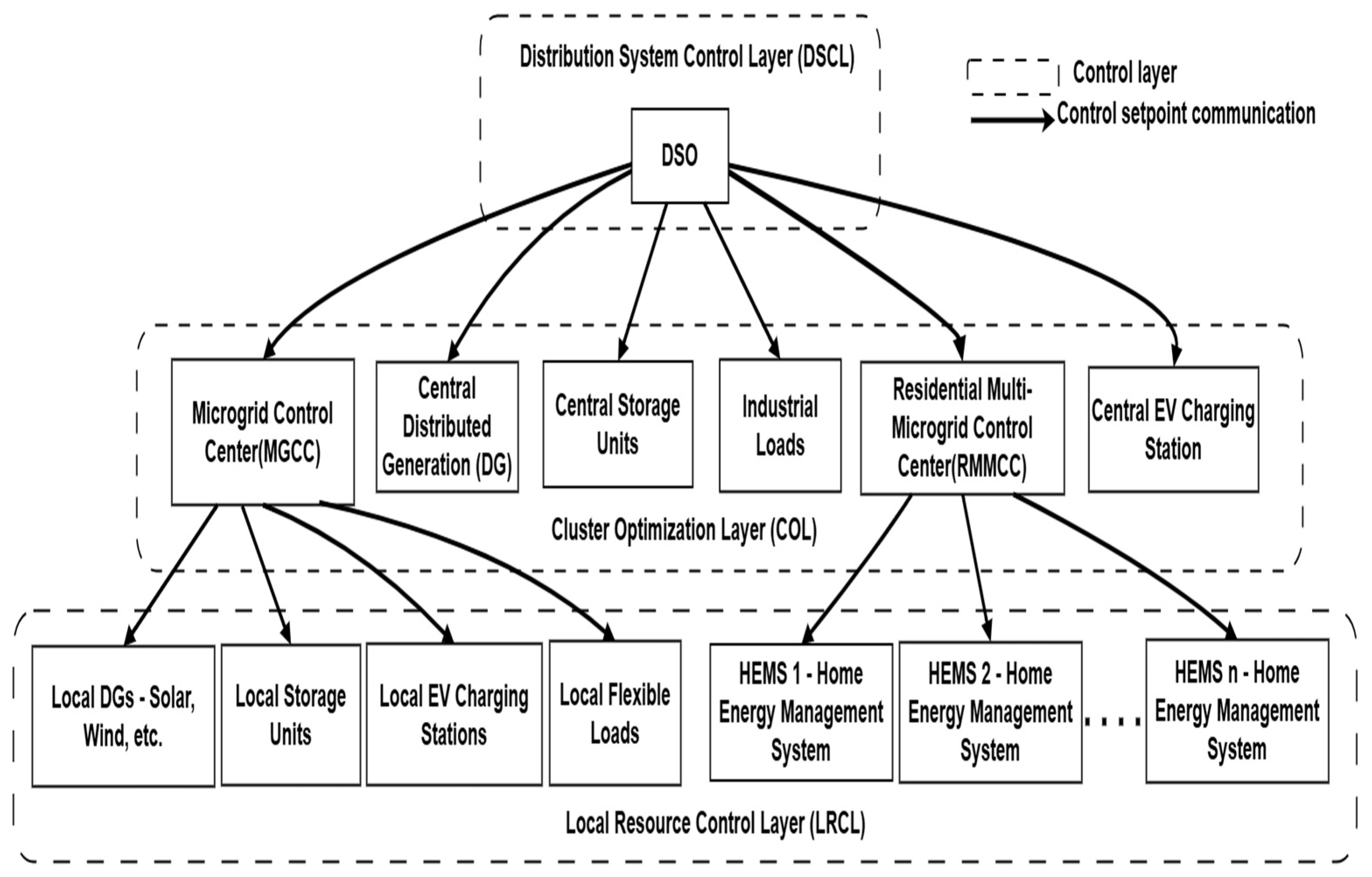
5] with a distributed hierarchical control system is adopted in this study. The various control layers of the SoS model are shown in
Figure 2, which consists of the Distribution System Control Layer (DSCL), Cluster Optimization Layer (COL), and Local Resource Control Layer. The overall system control is orchestrated by the DSCL in collaboration with the COL, which manages control nodes within the MV grid. COL comprises diverse control entities, including the MGCC, Central Storage Units, Central Distributed Generation, Residential Multi-Microgrid CC, Central Charging Stations, and Industrial Prosumers, all operating at the MV level. The COL further supervises the Local Resource Control Layer (LRCL), which is responsible for managing LV control nodes under its jurisdiction. For instance, the MGCC dispatches control power setpoints to its subordinate local nodes, such as local storage units, local EVCS, and Distributed Generation (DG) units.
In this control framework, the Distribution System Operator (DSO) acts as the supervisory entity of the distribution system, while key components such as the MGCC, RMMCC, HEMS, Electric Vehicle Charging Station (EVCS), and Renewable Energy (RE) units function as subordinate yet intelligent agents. Each of these agents locally controls its respective subsystem and responds to control directives from the DSO for specific grid-level tasks, such as ancillary services, coordinated fault recovery, and flexibility provision. These agents are hierarchically integrated into the bulk power distribution system and are capable of exchanging information under a structured optimization framework. The advantage of this System of Systems (SoSs) architecture lies in its ability to preserve the functionality of upper-level control centers wherein the DSO’s control center (CC) may align with the role of a primary distribution substation—while enabling local decision-making. The microgrid operates as an autonomous system within this hierarchy, whereas clusters of microgrids/residential microgrids are coordinated by their respective control centers under the oversight of the DSO. Additionally, at the medium-voltage level, integration of grid-scale storage systems, large-capacity EV charging stations, and RE generation plants is facilitated.
The SoS-based structure further supports the implementation of local energy markets, where each intelligent agent can actively participate by submitting bids based on its operational state and energy flexibility. The DSO coordinates various functionalities as discussed above with the help of a large network simulator and optimizer model, which provides the optimal operating conditions/control setpoints of its subordinate layers [
23]. The Energy Management System (EMS) of the microgrid, referred to as the Microgrid Control Center (MGCC), locally manages its resources by sending power setpoints through communication links, based on the solutions obtained from local optimization tools. Similarly, residential microgrid clusters are managed by an RMMCC and each home by its CC, the HEMS [
24]. RMMCC acts as an aggregation point of various resources for distribution grid support functions from the microgrid cluster.
To enable upper grid functionalities such as ancillary services and flexibility services for the Transmission System Operator (TSO) or adjacent smart distribution grids, it is essential to operate the Smart Distribution System as a unified, controllable entity. Achieving this level of coordination demands the implementation of a hierarchical System-of-Systems (SoS) control strategy. In this framework, the TSO communicates specific service requests to the DSO, detailing the nature and extent of the required grid support. Based on the availability and capability of distributed resources, the DSO issues appropriate control setpoints to major system components such as energy storage units, EVCS, MGCC, and RMMCC, ensuring a coordinated response to grid service demands. If an SoS control structure is not adopted, the DSO would have sent control signals to each local DG unit, which requires a complex communication topology and sometimes cannot ensure the activation of the requested service. This SoS method preserves the privacy of all systems, as all units communicate their status only to the upper control layer, which limits the complex data transfers to the upper control layers and saves the additional communication needed.
Figure 2.
Control and communication layers in the smart distribution grid with hierarchical SoS communication structure. To achieve a cohesive and controllable operation of the smart distribution system, power setpoints must be hierarchically transmitted across multiple control nodes. Communication between components in a smart grid is extremely important for maximizing the reliable and cost-effective use of available electrical power [
25]. Thus, smart grids and smart distribution grids are highly vulnerable to cyberattack. To address the various challenges related to cyber vulnerabilities, it is necessary to identify the critical infrastructure and vulnerable nodes of the SDS. This hierarchical structure inherently introduces cyber-vulnerable control links, which could be targeted by false data injection (FDI) attacks. Malicious actors can exploit these vulnerabilities to manipulate control setpoints, leading to a false perception of system stability and ultimately causing maloperation. Given these cybersecurity risks, it is imperative to implement robust cybersecurity measures across all control layers to ensure the integrity, reliability, and resilience of the smart distribution system. Electric Vehicle Charging Stations (EVCSs) [
26] are not cyberattack-resistant because they depend on communication systems to share information with the smart grid and can be exploited by attackers, which may harm the power grid stability by triggering simultaneous charging to create peak loads on the power grid, eventually leading to a large-scale blackout [
27].
![Energies 18 03916 g002]()
False Data Injection (FDI) attacks are common among delivery-based categories and can be applied to all layers of a cyber-physical system. Additionally, FDI poses greater risk and danger to the power system operation. Model-based and data-driven detection algorithms are typically used to detect FDI attacks. Model-based detection algorithms can be divided into estimation-based and direct calculation methods. Data-driven detection algorithms are model-free, and the system parameters or models are not involved in the FDI attack detection process [
28,
29]. A comprehensive review of obfuscated malware and the promise of hybrid and AI-based detection, including a Generative AI–digital twin framework for real-time defense, is suggested in [
30]. An intelligent anomaly detection method for the smart distribution grid is discussed in [
31], while a structured approach to threat modeling, attack simulation, and mitigation for EV charging infrastructures is presented in [
32], and an attack detection and mitigation method during EV charging station–based ancillary services is discussed in [
33].
Conventional research has dwelt on anomaly detection systems for smart distribution grids, incorporating both offline and online-compatible detection methods. However, these approaches primarily focus on the evaluation of detection accuracy, bypassing assessment of their effectiveness under real-time grid conditions. Albeit these methods successfully identified cyber anomalies, they are deficient in corrective control strategies that enhance system resilience. In contrast, this study introduces an online, real-time compromised data detection framework specifically designed to counter FDI attacks that exploit cyber-vulnerable control links across multiple hierarchical layers, including the DSCL to the COL and COL to the LRCL. Cyber resilience is exigent during grid emergencies, where preclusion of false control actions is unassailable for assurance of sustained system stability under critical operating conditions. The proffered framework not only detects cyber anomalies but also triggers corrective, resilience-enhancing regulatory actions, ensuring a secure, fault-tolerant smart distribution system in real time.
3. Cyber-Resilient Control Strategy for the Smart Distribution System
The term ‘resilience’ with respect to cyber-physical systems is the capability to alleviate the severity and extent of the disruption; besides, it is about the moderation of unanticipated, inestimable failures from historical data; resilience assessment depends on the temporal dimension of the main disturbances and their remedial actions [
34]. For any cyber-physical system, it is imperative to assume cyberattacks or physical failures, reinstated by disaster recovery plans in the event of compromised systems [
35]. For the design of system control strategies, the system operational conditions can be conceptually classified into five states: Normal, Alert, Emergency, In-extremis, and Restorative [
36]. Besides conventional cyber threat detection strategies, the incorporation of risk mitigation/reduction controllers is called for to reject the control commands that may jeopardize system stability under an emergency or in-extremis state to preclude the system from blackouts and ensure cyber resiliency. In a hierarchical SOS control framework, the DSO transmits the required power reference setpoints to the respective COL [
37]. The COL, in turn, appraises the local system conditions and accordingly dispatches control signals to the LRCL, sustaining coordinated power management and operational stability across the distribution network [
38]. Communication links’ susceptibility to data manipulation attacks warrants assessment of the impregnability of the received control setpoints, based on the current state of the system.
The proffered cyberattack prevention method is consonant with Ref. [
39] on the cybersecurity approach for cyber resilience improvement. Ref. [
40] stipulates the imperative hampering and prevention of misuse of energy delivery services (EDSs) at every level, detection of attempts to execute unneeded functionality that the EDS was not designed to support, and detection of attempts to misuse the EDS functionality that should never have been executed. The control subsystem should be outfitted to adjudge whether the received commands support grid stability for the given system operation conditions. If a command unsettles system stability, it is designated malicious and must be rejected. This study considers that the attacker is able to inject spurious control information (FDI attack) into controllers of each system in the SOS during the Emergency or Restorative state of the distribution system. Such assaults are worse than the attacks under steady-state conditions, as they may cause the system to intrinsically move to an extreme state, thereby operating under-/over-frequency relays, under-/over-voltage relays, etc., which will drive the system into an in-extremis state and finally black out. The proposed system embodies an anomaly detector for various controllers in an SDS to enhance the distribution system resilience pursuant to a cyber anomaly and its integration with droop controllers of DGs in MV and LV lines. In this way, the anomalous control setpoints from its upper controllers are identified, and the system resilience is enhanced by preventing the system from transitioning towards unstable operating conditions during destabilized and emergency system states. The effectiveness of the proposed controllers, modeled via MATLAB/ Simulink, was verified under diverse anomalous conditions.
4. Principle of Cyber-Resilient Controllers
The following sections present the spatial relationship among control nodes, their dependencies on grid control layers, and the modeling approach for cyber-resilient control at each layer.
4.1. Grid Dynamics
The modeling of cyber-resilient controllers and anomaly detection mechanisms should account for spatial distributions of the controllers and grid systems, whose performance is affected by variations in the system under control’s operational state. A comprehensive analysis of the dependency between active and reactive power on voltage and power angle delta in typical LV and high-voltage (HV) lines is unavoidable to ensure well-conditioned controller design. In addition, classification of the power transmission lines as HV, MV, or LV must be factored in to optimize the control strategies.
For a typical transmission line with sending end voltage
and receiving end voltage
, an impedance of the line connecting the two ends is
, based on the power flow equation, the following relations can be derived [
41]:
The typical line parameters of transmission and distribution systems can be found in [
42]. For an HV transmission line, the resistance
R is negligible compared to the inductive reactance
X, rendering the line as predominantly inductive in nature. Additionally, for small power angles (
δ), we can assume sin
δ ≈
δ and cos
δ ≈ 1. Under these assumptions, the active power (
P) and reactive power (
Q) can be expressed as follows:
Thus, in an HV transmission line, the active power P can be regulated by varying the power angle δ, while the reactive power Q can be controlled by adjusting the voltage magnitude. Detecting the phase of the output voltage is a challenging task [
43]. A common approach is to adjust the output voltage frequency to regulate the phase, thereby controlling the real power output of the DG inverter. This approach has also been extended to medium-voltage lines in [
44,
45].
Equations (5) and (6) describe the droop control mechanisms in HV lines, where f is the operating frequency, is the system nominal frequency, and m represents the droop coefficient, defining the relationship between frequency deviation and power output in the conventional droop control method.
The
R/X ratio of LV lines is significantly higher compared to HV lines [
46]. Reactance of LV lines, being much smaller than the resistance, is negligible; thus, LV lines are effectively resistive in nature. The power angle (
δ) and voltage change (
ΔV) can be derived from the active and reactive power equations of Equations (1) and (2), expressed as shown in Equations (7) and (8).
4.2. Feature Selection for Model Training Based on Grid Dynamics
Thus, from Equations (7) and (8), it is clear that in LV lines, the active power
P primarily depends on the voltage variation (
ΔV), while the reactive power
Q is influenced by the power angle (
δ). As a result, the conventional (
P-
f) and (
Q-
V) droop control methods are ill-suited for LV microgrids [
47,
48]. In an LV microgrid, the active power is primarily controlled by voltage (
P-
V droop control), rather than frequency, unlike the conventional (
P-f) droop control method [
47,
48]. This is due to the resistive nature of LV lines, where the active power can be regulated by adjusting the voltage, while reactive power is restrained by frequency. Furthermore, most DG units in microgrids are power-electronically interfaced, which means they lack the significant inertia found in conventional systems [
49]. It is necessary to identify the current operating state of the grid to verify whether the control setpoint is implementable or not. The system state cannot be reliably identified using global information from the DSO, as this data may be compromised or corrupted. Therefore, a robust approach proposed in this study is to base measurements on local information from control nodes, ensuring greater accuracy and resilience against potential cyber threats.
Control nodes in MV grids can sense local voltage and frequency to determine the system’s operating state, as defined in Equation (5). In contrast, LRCL nodes can utilize local voltage measurements due to the coupling between active power and voltage, described in Equation (8). To detect cyber anomalies in control power reference setpoints from the upper control nodes, artificial neural networks (ANNs) are utilized, incorporating the dynamic characteristics of both MV and LV grids. Detailed modeling of the ANN-based anomaly detection system is presented in the following section.
4.3. Cyber-Resilient Controller Modeling
On the detection of an anomaly, the associated DGs can transition into one of two possible operating modes: (i) isolation from the network or (ii) autonomous operation until valid control setpoints are received. As isolation is not a viable option for the realization of cyber resilience, it may further destabilize system operation. Therefore, the autonomous mode is preferred, where each controller independently regulates its control system without relying on communication with upper control layers. (In this study, autonomous mode does not imply islanded operation.)
Droop controllers are routinely employed for autonomous operations of grid-connected inverters [
50]. Droop control enables inverters of the grid-connected system to share load and maintain stability for systems where communication channels are unreliable. This method mimics synchronous generators and supports decentralized control. Autonomous operations of individual DGs are realized using droop controllers. (
P-
f) droop controllers work well only for HV and MV grids where the
R/X ratio is low (highly inductive lines) [
51]; thus, (
P-
V) droop controllers are preferred for LV grids (highly resistive lines) [
52], whereas (
P-
f) droop controllers are employed for MV grids. The droop controller design for this study was based on Ref. [
53], where detailed modeling and governing equations can be found.
4.3.1. Principle of Droop Controller for MV Grids
According to Equation (5), there exists a linear relation between active power (
P) and system frequency (
f). Equation (5) can be written as follows:
where f is the inverter frequency,
is the nominal system frequency (50 Hz or 60 Hz),
is the rated active power output of the inverter,
is the reference active power, and
is the droop coefficient, determining the sensitivity of frequency to power deviation for the MV grid.
Droop coefficient is related to frequency and active power as follows:
where
is the allowable frequency deviation and
ΔP is the maximum active power injection range. The droop control feature enables the inverters to autonomously modify their output in response to the load changes, bereft of frequency variations ensuing from changes in the power usage.
4.3.2. Principle of Droop Controller for LV Grids
Equation (8) reveals a linear relation between active power (
P) and system voltage (
V) in LV grids that are highly resistive in nature. Thus, the droop control can ensure that an increase in the voltage due to the increased active power generation can be modulated by regulation of the active power generation, and vice versa. The droop control equation of the LV network can be derived from Equation (8) as follows:
where
V is the terminal voltage of the inverter,
is the nominal voltage of the LV grid,
is the rated active power output of the inverter,
is the reference active power setpoint, and
is the droop coefficient for (
P-
V), determining the voltage sensitivity to active power changes, defined hereunder as follows:
where
ΔP is the maximum allowable active power injection corresponding to the maximum permissible voltage deviation, and
ΔV is determined by the system’s operational limits and available generation capacity.
4.4. ANN-Integrated Droop Control for Cyber Resilience
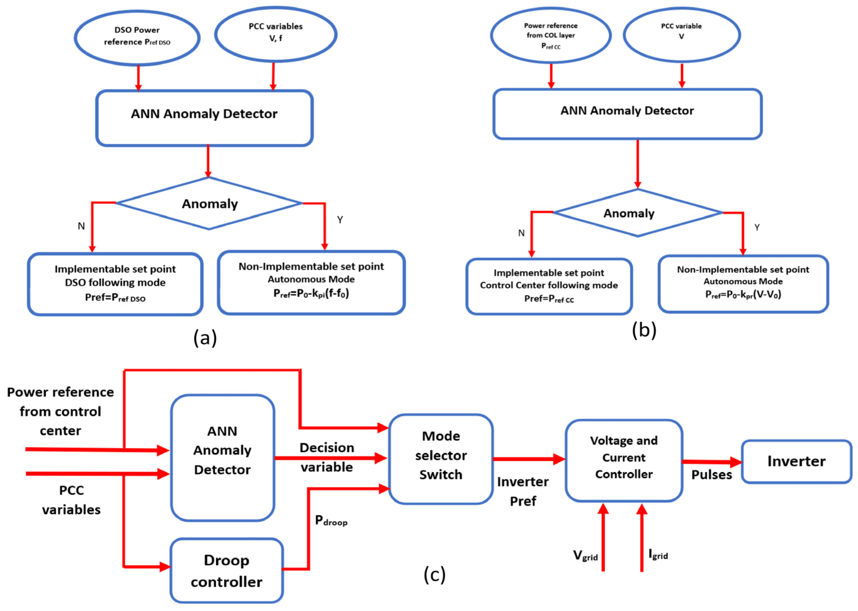
The operational framework of the cyber-resilient controllers implemented in the COL and LRCL is depicted in
Figure 3a,b. The integration of an artificial neural network (ANN) with the droop controller is illustrated in
Figure 3c, highlighting the adaptive control mechanism.
When the anomaly detector identifies a control signal as a potential cyber threat, which, if executed, could compromise system stability, the mode selector dynamically switches the control reference to autonomous droop control [
31]. In the autonomous mode, DGs operate based on the droop controller’s power reference, utilizing (
P-
f) or (
P-
V) droop control strategies depending on their location within the network. During emergency conditions, the DGs autonomously adjust their power injection or absorption in response to grid requirements, sustaining grid resilience. The mode selector’s power reference output is subsequently fed into the voltage and current controllers, which regulate pulse generation for the inverters, ensuring seamless grid support and operational stability.
5. System and ANN Controller Modeling
This section presents the modeling of the distribution system and the underlying principles of artificial neural network (ANN)-based detection of compromised data across various control layers in a smart distribution grid.
5.1. System Modeling
To evaluate the robustness of the proposed cyber-resilient controller, a modified IEEE 33-bus distribution system [
21] was implemented in MATLAB/Simulink. The smart distribution system model is composed of two COL control elements: a microgrid and a central storage unit at buses 30 and 7, respectively. The distribution grid was modeled as a weak grid to judiciously appraise the cyber-resilient controller’s performance under siege. The central storage unit is responsible for providing dynamic energy support to the 12.66 kV medium-voltage grid by injecting or absorbing active power based on control signals from the DSO. The storage unit has a capacity of 250 kW, and the droop controller is parameterized as
= 240 kW/Hz. The MGCC communicates real-time setpoints to the LRCL, constituted of DG units, storage systems, and flexible loads. LRCL regulates power injection and absorption based on grid requirements.
To evaluate the anomaly detection system, an LV (415 V) microgrid was modeled with 100 kW generation capacity, a 200 kW active load, and a 20 kVAR reactive load. The system was tested against FDI attacks, where malicious entities manipulate control signals exchanged between the DSO and the central storage units MGCC and local storage units in the LRCL layer. These cyberattacks alter control setpoints, leading to erroneous power commands, which can destabilize the grid. This study was focused on storage units, as they exhibit greater adaptability, making them more vulnerable to cyber-induced control anomalies. The droop controller parameter for the storage unit in the MG (LRCL layer) is selected as 0.35 kW/V.
5.2. Anomaly Detection Using Artificial Neural Networks
To detect cyber anomalies in power reference setpoints, an ANN-based anomaly detection model was designed in MATLAB/Simulink using the pattern recognition and classification app. A two-layer feedforward neural network with sigmoid hidden neurons and SoftMax output neurons was implemented, ensuring high accuracy in classification tasks. The dataset for ANN training was carefully curated, incorporating normal operating conditions and anomalous conditions due to FDI attacks or operator errors.
5.2.1. Feature Engineering and Preprocessing
The following input features are utilized: voltage and frequency at the Point of Common Coupling (PCC), power reference setpoints from the DSO, and upper control layers. To ensure uniform scaling, all input features are normalized using min-max scaling. Since the dataset was explicitly designed with predefined normal and anomalous conditions, additional outlier detection techniques were not required. The dataset was partitioned as follows: 70% Training, 15% Validation, and 15% Testing. This ensures a balanced representation of both normal and attack scenarios, improving the model’s robustness and generalization.
5.2.2. Modeling of ANN-Based Anomaly Detector for MV Grids
The modeling of ANN for compromised control setpoint determination is based on the principle of MV grid as per Equations (3) and (5). The features were selected based on the location of DG in the distribution grid.
Let
represent the feature vector of the MV system at any time
t, where
n is the number of features (
n = 3 for ANN controllers in the MV grid, where the features are the active power reference from the DSO
, the system frequency (
f) measured at the PCC, and the voltage at the PCC
.
Let
be the label, where
indicates normal behavior and
indicates an anomaly (attack). The neural network aims to learn a function
where
represents the learnable parameters of the neural network, such that the predicted output
is as follows:
The relevant types of data manipulation attacks considered in this study involve false data injection (FDI), specifically false command injection (FCI). In FDI, fake sensor or control parameter readings are injected, deviating from expected patterns. FCI refers to the injection of compromised control setpoints that deviate from the intended control actions. In this study, it is assumed that such compromised data injections occur during system contingency conditions, where frequency, voltage, and other parameters deviate from normal operating values. Though the deviation from the optimal setpoints is critical in terms of economic perspective, the situation can cause serious stability issues while implementing the compromised control setpoints during grid instabilities. It is necessary to model the adversary injection of false data, the error in the system under study, or the human-induced errors. This is modeled by defining a completely new set of data
, where
where
Here,
r is a randomly generated data point that deviates significantly from the original data, and
controls the magnitude of the deviation. As per the control principle used in the current study, the power references are only sent to the local control nodes; voltage and frequency are measured at the PCC of the controller, hence fewer chances for data injection and manipulations. Since the power reference is being transferred over the network, this control variable is subjected to the data manipulation/error, etc. An injected attack could modify the reference power value from the DSO:
where
is the actual power reference power value from the DSO and
represents an unauthorized deviation from the regular reference.
The normal data were generated from MATLAB/Simulink, and the anomalous data were augmented with original data based on the attack vectors. Modeling of the neural network included the following steps. Let the data for training be defined as follows:
where
represents the feature vector and
is the label for the MV grid. A binary cross-entropy loss function as per Equation (20) was used to train the network for binary classification:
where
is the predicted probability for the
ith sample and
is the true label. The parameters
of the neural network were updated using gradient descent.
where
η is the learning rate and is the gradient of the loss function with respect to the parameters
. This ensured that the neural network minimized the loss by adjusting the parameters based on the training data. During testing, as seen in Equation (22), the neural network computes the output
for a new data point
:
If
the data point is classified as an anomaly; unlike
classifies it as normal behavior. Since the neural network uses a SoftMax activation function in the output layer to provide probabilistic predictions, which need to be interpreted as binary outcomes for the control logic, a threshold is fixed. The control setpoint is an anomaly if
. In binary classification problems, a threshold of 0.5 is commonly used in the literature, as it provides a simple and efficient way to convert probabilistic outputs into discrete decisions [
54].
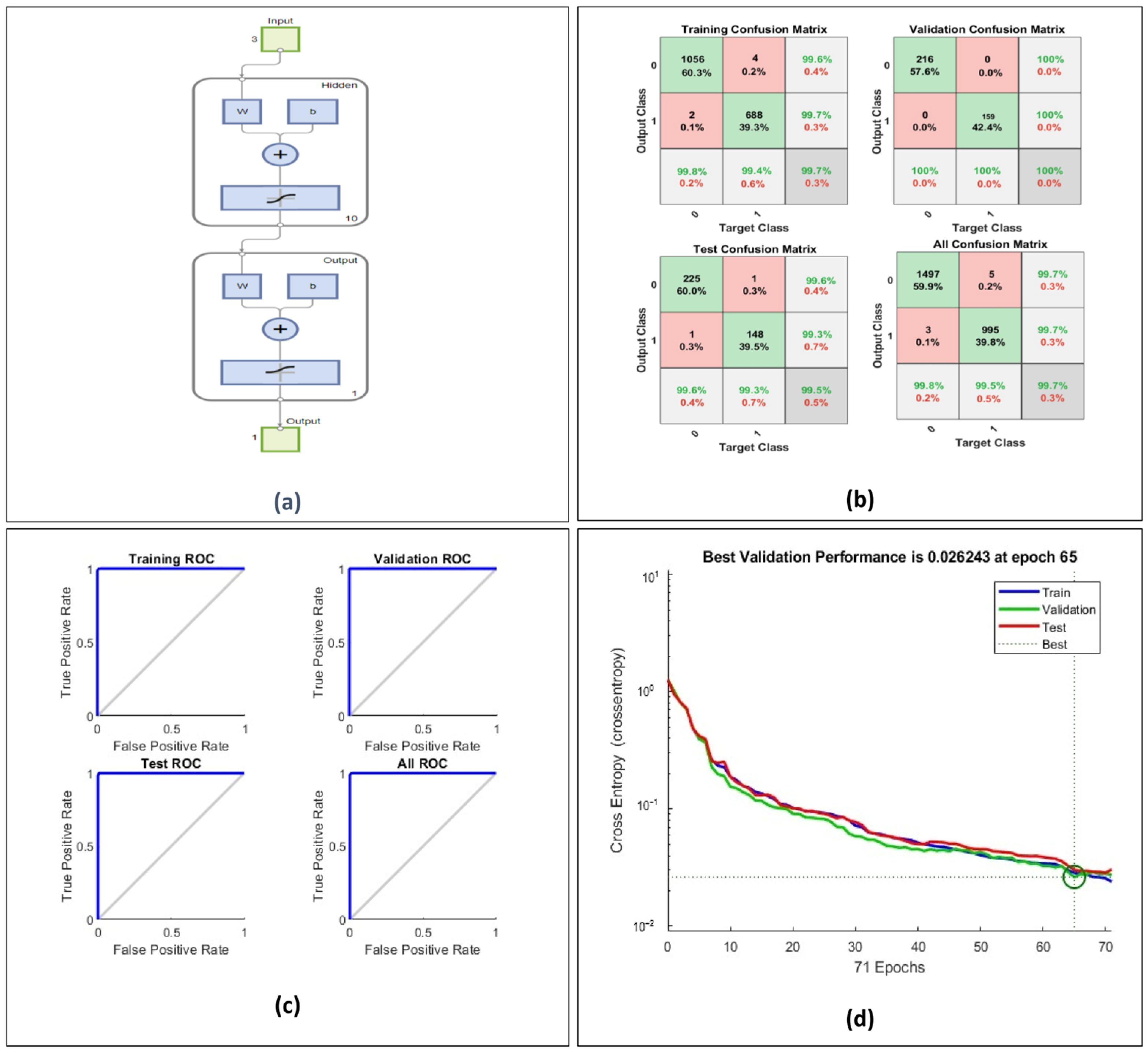
The ANN-based anomaly detection model was evaluated for cyber-resilient control in the COL, where the optimal performance of ANN was achieved with 10 hidden neurons in the feedforward network. Using MATLAB’s ANN Toolbox, diverse network configurations were tested, and the best classification accuracy was observed with this architecture.
Figure 4a shows the architecture of the artificial neural network used. It consists of an input layer with 3 features, 10 hidden neurons, and an output layer with a single neuron. The performance evaluation, as presented in
Figure 4, demonstrates high classification accuracy, with training, validation, and test accuracies exceeding 99%, as observed in the confusion matrix results.
The minimal false positives and false negatives reaffirm the model’s efficacious anomaly classification capability. The ROC characteristics exhibit an AUC ≈ 1.0, reasserting the ANN’s ability to distinguish between normal and anomalous control setpoints with high precision. The cross-entropy loss convergence at epoch 65 indicates stable model training, with no significant overfitting, as evidenced by the closely aligned training and validation loss curves. The evaluation metrics presented in
Table 1 highlight the robustness and reliability of the ANN controller in the COL layer of the MV grid for effectively managing cyber-influenced control scenarios. These results validate the effectiveness of the proposed ANN model; testing of the controllers with real-time anomalies under grid test conditions is explored in
Section 6.1.
In the confusion matrices, green cells indicate correct classifications (true positives and true negatives), while red or pink cells highlight misclassifications. Gray cells represent summary statistics including class-wise precision and recall.
5.2.3. Modeling of ANN for LV Grids
The modeling of ANN for anomaly control setpoint determination is based on the principle of LV grid as per Equation (8). The features were selected based on the location of DG in the distribution grid, that is, the DG’s PCC voltage and the power reference from the upper control layer. Let
represent the feature vector of the LV system at any time
t, where
n is the number of features (
n = 2 for ANN controllers in LV grid) and the features include active power reference from COL(
), and the PCC voltage,
Let
be the label, where
indicates normal behavior and
indicates an anomaly (attack). The neural network aims to learn a function
where
represents the learnable parameters of the neural network controller in the LV grid, such that the predicted output
as follows:
In the present study’s control framework, power references are transmitted exclusively from the MGCC to local storage control nodes. As these references are communicated over the network, they are prone to data manipulation or errors. An injected attack could modify the reference power value. However, as voltage is measured at the controller’s PCC, the risk of data injection or manipulation is mitigated. The altered or incorrect power reference setpoint is defined as follows:
is the actual power reference power value from the DSO, and
represents an unauthorized deviation from the regular reference. Once the normal and anomalous data (with attack vectors) are generated, the neural network can be trained. The data for training is defined as follows:
where
represents the feature vector and
the label for the MV grid. A binary cross-entropy loss function was also adopted to train the network for binary classification:
where
is the predicted probability for the
ith sample, and
is the true label. The parameter
of the neural network was updated using gradient descent:
where
, the learning rate,
is the gradient of the loss function with respect to the parameters
. This ensures that the neural network minimizes the loss by adjusting the parameters based on the training data. During testing, for a new data point
, the neural network computes the output:
If the data point is classified as an anomaly, while classifies it as normal behavior. Since the neural network uses a SoftMax activation function in the output layer to provide probabilistic predictions, which need to be interpreted as binary outcomes for the control logic, a threshold is fixed such that if .
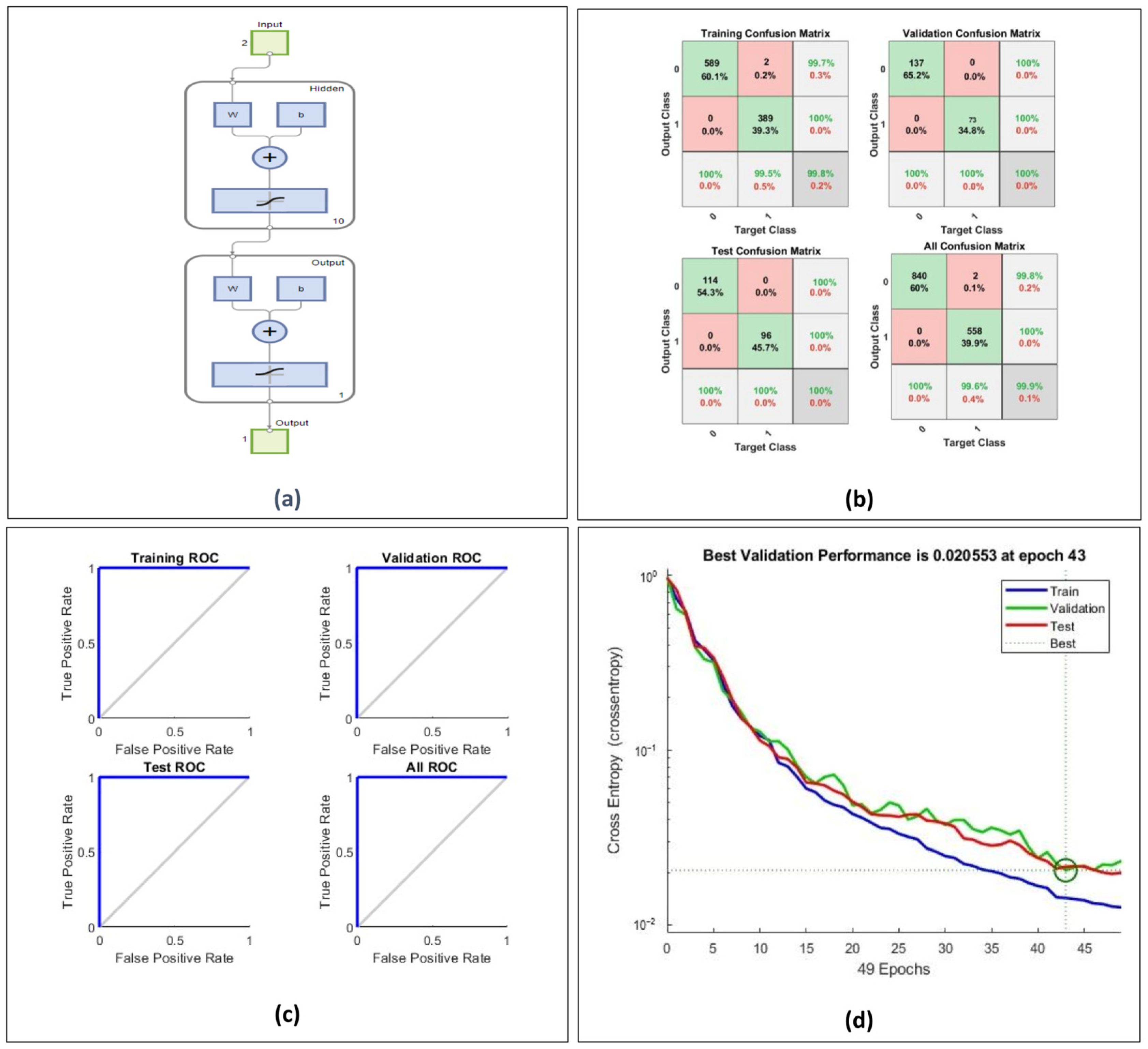
The threshold of 0.5 was chosen, similar to the controllers in the MV grid. The ANN-based anomaly detection model was evaluated for cybersecurity in the LV grid; the optimal performance was achieved with 10 hidden neurons in the feedforward network. This architecture was derived via MATLAB’s ANN Toolbox, where different configurations were tested, and the best performance was observed with 10 hidden neurons. The final trained model demonstrated a classification accuracy above 98%, as observed in the confusion matrix results (
Figure 5). The ROC characteristics exhibit an AUC ≈ 1.0, confirming the model’s ability to detect cyber anomalies with high precision. The cross-entropy loss curve indicated stable model convergence at epoch 43, ensuring reliable classification performance.
Table 2 summarizes the evaluation metrics of the ANN controller deployed in the LRCL layer of the LV grid, indicating a reliable and accurate performance in detecting and mitigating cyber-compromised control commands.
These results validate the effectiveness of the proposed ANN model. Further evaluation of the controllers under closed-loop MATLAB simulation scenarios, reflecting grid test conditions, is presented in
Section 6.2.
6. Performance Evaluation of Cyber-Resilient Controllers Under Compromised Control Setpoints
A MATLAB/Simulink-based test system was developed as discussed in
Section 5.1, integrating ANN-based anomaly detectors and droop controllers to assess the distribution system performance under various anomalous control setpoints from the DSO and COL layers. The DGs were modeled as dispatchable energy storage units capable of active power injection and absorption, enabling dynamic analysis of distribution system response. To evaluate the system’s robustness, cyberattack scenarios were simulated on MV and LV grid controllers, examining the effectiveness in preventing the system from moving towards instability. The following cases illustrate the controller’s effectiveness in mitigating FDI onslaughts and their impact on overall system stability.
6.1. Validation of Cyber-Resilient Control in the COL of the MV Grid
To evaluate the performance of the proposed control framework in identifying false control signals from the Distribution System Operator (DSO), this study focuses specifically on the medium-voltage (MV) energy storage system, rather than all components of the Control Layer (COL). The MV storage system is particularly suitable for this analysis due to its bidirectional power capability: both absorption and injection, allowing for comprehensive testing under varying operational conditions. The system and controller parameters employed in this study are detailed in
Section 5.1. The primary objective is to assess the ability of the artificial neural network (ANN) to accurately detect non-implementable control signals while simultaneously ensuring that the associated droop controller can maintain autonomous operation during instances of anomalous inputs. This autonomous response mechanism enhances the cyber-resilience of the system by preventing the distributed generator (DG) from transitioning to an offline state in response to compromised control signals.
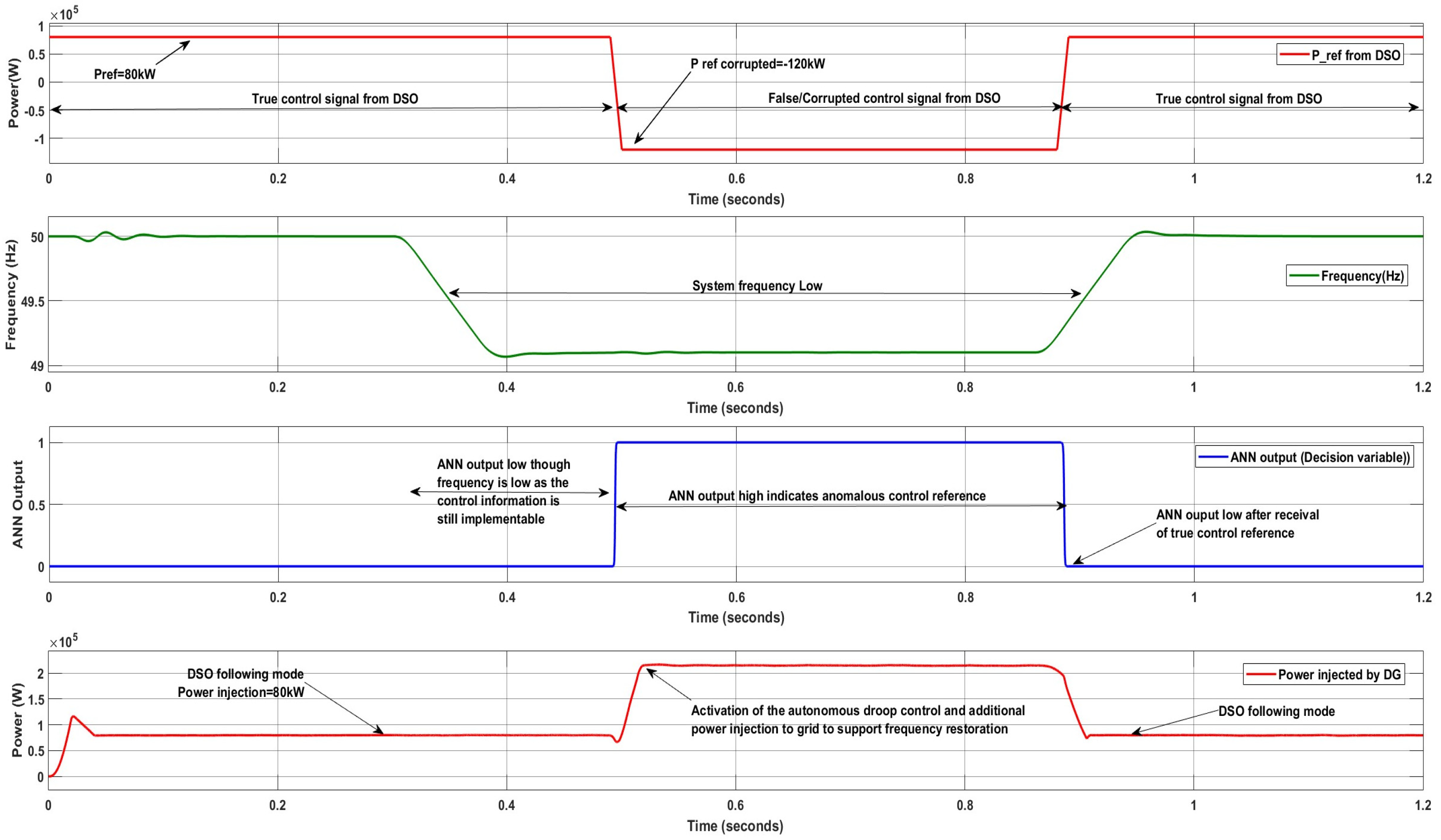
6.1.1. Cyber-Resilient Controller Response Under Low-Frequency Event
Figure 6 presents the response of the cyber-resilient controller under a low-frequency event in a medium-voltage system. Till 0.5 s, the DG (storage) controller at the COL followed the DSO setpoint, generating 80 kW. At
t = 0.3 s, a low-frequency event is simulated (to mimic the effect of fault recovery or the loss of a primary generating unit). At
t = 0.5 s, the DG controller received an anomalous setpoint instructing it to consume 120 kW (−120 kW). The ANN-based anomaly detector successfully identified this as an FDI attack (ANN output = 1), rejecting the malicious setpoint and transitioning DG into autonomous operation. If this reference setpoint were implemented, the frequency of the system may further worsen, and an ANN controller successfully rejected the malicious control setpoint. During autonomous mode (
t = 0.5 s–0.88 s), the DG injected additional power using droop control, assisting in system recovery. The DG will remain in autonomous mode until the system returns to stable conditions or a valid setpoint is received. In this scenario, at
t = 0.89 s, the precise setpoint was received, allowing the DG to resume following the DSO command.
6.1.2. Cyber-Resilient Controller Response Under High-Frequency Event
To appraise the controller’s robustness under a high-frequency event, a high-frequency scenario is simulated (e.g., to mimic excess renewable generation, etc.) from 0.5 s to 0.9 s. An FDI attack was simulated in the communication link between the DSO and grid-level storage unit. As shown in
Figure 7, till 0.5 s, the controller was receiving the true control signal from DSO (
= −50 kW) and was following the DSO with power absorption of 50 kW. At
t = 0.5 s, the control setpoint was manipulated, instructing the DG to inject 120 kW (+120 kW) to the distribution system under the high grid frequency operating state. The ANN-based detector successfully identified this malicious setpoint and triggered a high-alert response, switching the system to autonomous droop/self-regulating mode. During the autonomous mode (
t = 0.5 s–0.88 s), the DG absorbed power from the grid, thereby mitigating the frequency deviation and ensuring the cyber resilience. The controller followed the DSO after the receipt of an implementable reference setpoint at
t = 0.9 s.
6.2. Validation of Cyber-Resilient Control in the LRCL of the LV Grid
The ANN-based anomaly detector and autonomous droop controllers for the low-voltage (LV) grid are integrated within the control elements of the Local Resource Control Layer (LRCL). To evaluate the effectiveness of LRCL controllers in identifying compromised control information from the COL, a scenario is considered in which the communication link between the MGCC and local DGs is assumed to be affected, leading to data manipulation, particularly in the interaction with low-voltage storage units within the microgrid. As previously discussed, the performance of the storage system controllers is evaluated under both power injection and absorption conditions. This dual-mode assessment under corrupted reference signal scenarios verifies the detection and cyber resilience capability of the ANN and droop controller.
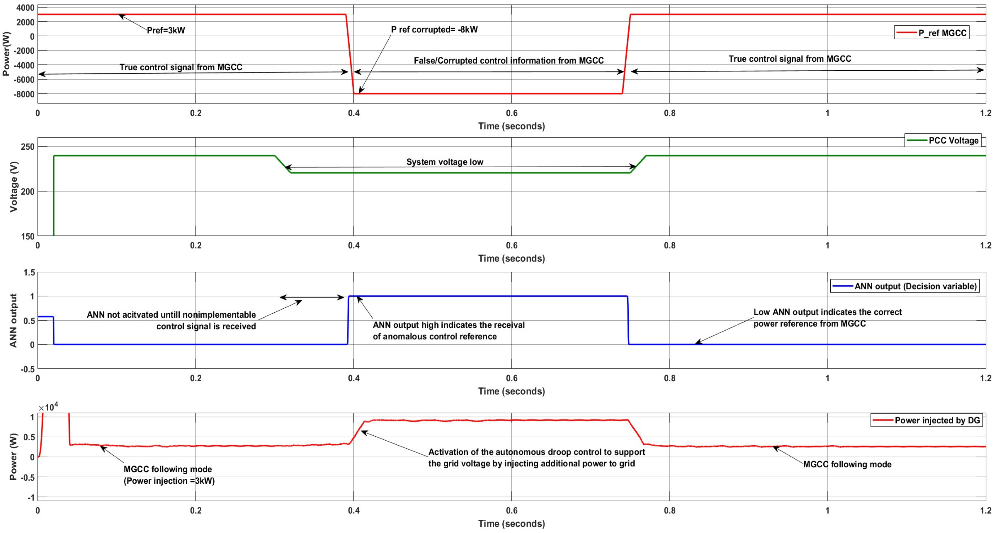
6.2.1. Response Under LV Condition
Figure 8 presents the system response under a data manipulation attack in the low-voltage (LV) microgrid. The LRCL controller of the storage-based DG initially followed the setpoint issued by the COL controller, specifically the MGCC, and delivered 3 kW (true control reference = +3 kW) until
t = 0.39 s. Between
t = 0.3 s and
t = 0.76 s, a low-voltage event is introduced to emulate a fault or load disturbance in the LV grid. At
t = 0.39 s, the DG receives an anomalous setpoint from the MGCC, instructing it to absorb 8 kW (−8 kW) despite the ongoing low-voltage condition. The ANN-based anomaly detector identifies this control command as suspicious (ANN output = 1), prompting a transition to autonomous control. During the autonomous operating period (
t = 0.4 s to 0.74 s), the DG injects active power based on droop characteristics to assist in voltage recovery. The system resumes normal operation at
t = 0.75 s upon receiving the valid control signal. This incident demonstrates the controller’s capability to maintain system support and enhance cyber-resilience in the presence of compromised control commands.
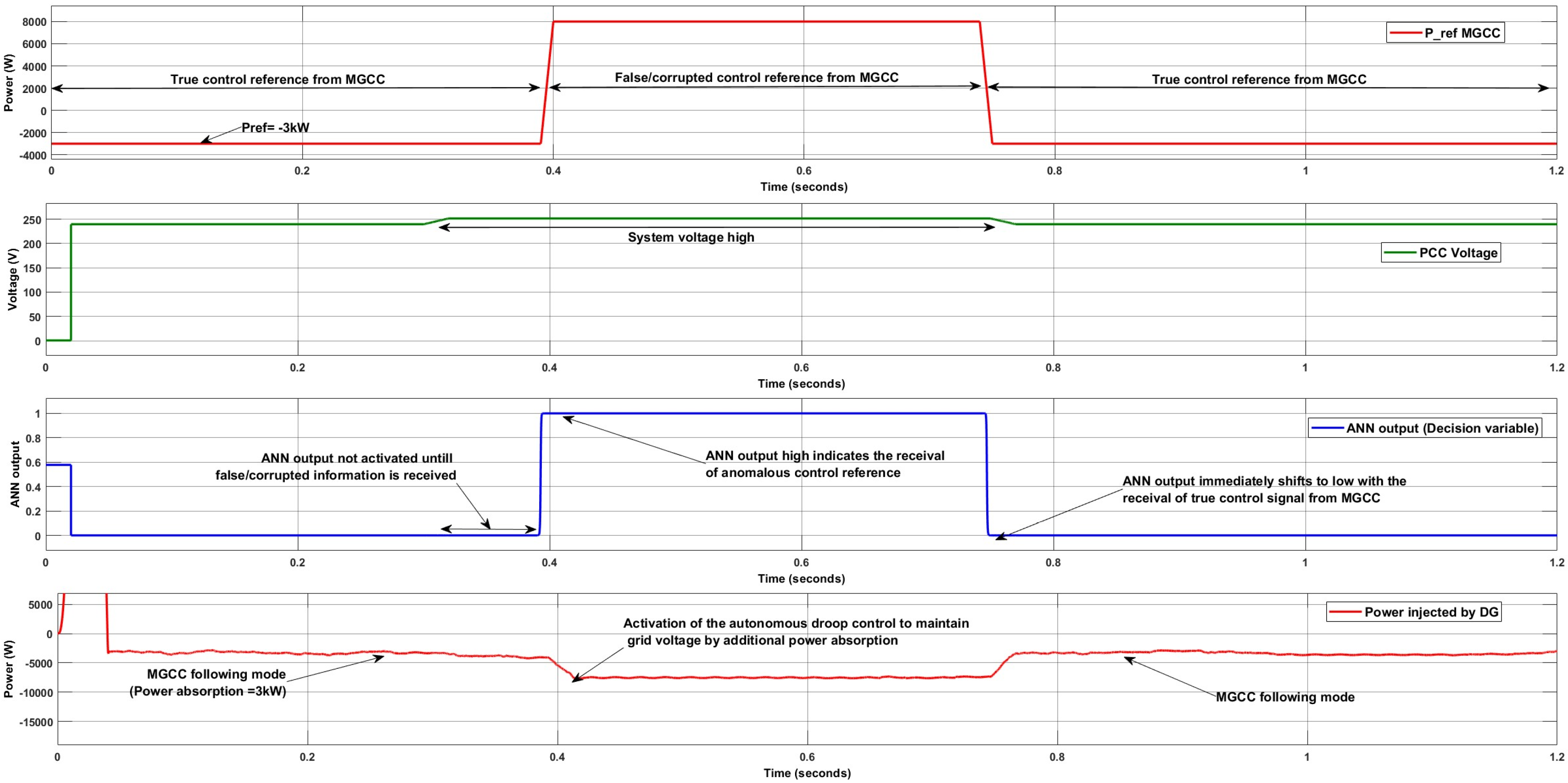
6.2.2. Response Under HV Condition
The response of the DG controller in the Local Resource Control Layer (LRCL) during a high-voltage grid condition and a compromised data attack is illustrated in
Figure 9. A high-voltage scenario is simulated between
t = 0.3 s and
t = 0.75 s to emulate conditions such as excess renewable energy generation. To evaluate controller performance under cyber threats, a False Data Injection (FDI) attack is introduced in the communication between the COL’s MGCC and the DG controller within the LRCL of the microgrid.
At t = 0.4 s, the attack alters the power setpoint, instructing each DG to inject 8 kW (+8 kW) into the grid during the already high-voltage condition. The cyber-resilient controller detects the anomalous command (ANN output = 1) and switches the DG operation to autonomous mode. Between t = 0.4 s and t = 0.74 s, the DGs operate autonomously by absorbing power from the grid, thereby mitigating potential system instability and assisting in voltage recovery. Once the correct reference signal is restored and no anomaly is detected, the ANN output returns to zero, enabling the controller to resume following the MGCC’s optimal setpoint.
6.3. Evaluation of Cyber-Resilient Metrics
Cyber resiliency metrics are inherently context-dependent and must be carefully curated based on the specific characteristics of the system architecture and the control strategy deployed [
55]. Accordingly, the cyber resilience metrics evaluated in this study to assess the response of the proposed control framework under compromised conditions are provided in
Table 3. The results indicate that the proposed methodology incorporates effective detection and mitigation strategies for anomalous control setpoints, thereby enhancing the cyber resilience of the system through rapid response mechanisms.
7. Discussion
The findings from
Section 6.1 and
Section 6.2 validate the effectiveness of the proposed cyber-resilient control framework in protecting the power distribution system from FDI attacks under various emergency conditions. The ANN-based anomaly detection mechanism enables real-time capable identification of erroneous setpoints, mitigating instability risks caused by compromised control command communication from the upper hierarchical control links. Additionally, the autonomous droop control mechanism ensures a seamless transition of DGs between upper controllers following (optimal operating) and grid-supporting modes, maintaining system stability even in the presence of cyber-induced anomalies. These results underscore the potential of AI-driven anomaly detection integrated with adaptive control strategies to significantly enhance the cybersecurity and resilience of future smart distribution grids.
The proposed methodology is designed to reject malicious control commands, particularly under emergency conditions where accepting a corrupted power reference signal could lead to system instability. However, even noise present in the signal during such conditions can have similar destabilizing effects and must therefore be treated with equal caution. To ensure secure operation, the algorithm must identify and reject noisy or corrupted signals. In contrast, local measurements such as frequency and voltage at the PCC can be measured with high accuracy using advanced digital signal processing techniques, which makes them more robust to noise and reliable for anomaly detection.
To ensure reliability during ANN malfunction, communication failure, or corrupted inputs, the system incorporates a built-in fallback mechanism that automatically switches to a droop-based control mode. This autonomous droop control, integrated as a core part of the architecture, ensures continued local operation and system resilience without reliance on external coordination.
The developed anomaly detection approach is based on a shallow neural network, which inherently offers low computational complexity, making it highly suitable for deployment on edge control node devices in Smart Distribution Systems (SDS). Unlike deep learning models that require extensive memory and processing power, the shallow ANN can be efficiently executed on low-power platforms such as Raspberry Pi, FPGAs, or embedded processors. The model structure was carefully designed to minimize the number of layers and neurons while preserving detection accuracy, thereby reducing inference time and memory overhead. Since the network operates in a single-sample, real-time inference mode, it avoids latency introduced by batch processing, ensuring prompt anomaly detection at the grid edge. These characteristics collectively make the proposed approach both computationally efficient and practically deployable, supporting real-time applications where reliability, responsiveness, and decentralization are critical.
While the presented results focus on compromised control setpoints between the DSO and storage units of the COL and between the MGCC and the local storage DG controller of the LRCL, a similar cyber-threat scenario can be reasonably extended to other communication links. In such cases, the respective control centers, equipped with anomaly detection and autonomous control logic, could override anomalous setpoints and maintain operational integrity, thereby supporting grid stability and enhancing overall cyber-resilience.
During autonomous operation, the local controllers operate based on a droop-based primary control mechanism, enabling decentralized decision-making without requiring real-time communication with other nodes or a central controller. This allows for fast and resilient control actions, which were validated under multiple test scenarios. However, a known limitation of droop-based primary control is the presence of small deviations in system parameters (e.g., frequency and voltage) from their nominal values. These deviations are acceptable within defined operational limits but may affect long-term system quality if not corrected. To address this, distributed secondary control strategies could be considered in future extensions to restore frequency and voltage to nominal values. Yet, such coordination relies on information exchange among local controllers, which introduces new challenges related to false data injection attacks and data integrity compromise in shared communication channels. Therefore, while distributed secondary control has the potential to enhance accuracy and coordination, any such implementation must be accompanied by robust cyber-resilient mechanisms to ensure secure, stable, and trustworthy operation under real-world conditions.
8. Conclusions
This study proposed a future-ready smart distribution grid architecture, outlining its hierarchical control framework and identifying potential cyber vulnerabilities across various control layers. To mitigate these risks, a novel cyber-resilient control strategy was introduced, designed to safeguard the control layers of the smart distribution system from cyber anomalies and prevent undesired operational states caused by both cyber threats and operator maloperation. Through extensive case studies, the effectiveness of the Cluster Optimization Layer and Local Resource Control Layer controllers integrated with ANN-based autonomous controllers in detecting anomalous control information from upper-layer controllers is validated. Instead of transitioning into an islanded mode, the proposed approach enhances cyber resilience by shifting compromised nodes to an autonomous operational mode, allowing distributed resources to actively support grid frequency and voltage. This mechanism ensures continued grid stability and resilience during cyberattack scenarios, reinforcing the robustness of the proposed hierarchical cyber-resilient control framework for future smart distribution systems. As part of future study, the model will be deployed on edge devices and tested for real-time performance and reliability using controller-in-the-loop (CIL) or real-time digital simulation (RTDS) platforms to validate its effectiveness.


