Article

Power Transformer Short-Circuit Force Calculation Using Three and Two-Dimensional Finite-Element Analysis

1
State Key Laboratory of Power Transmission Equipment Technology, Chongqing University, Chongqing 400044, China
2
State Grid Xinjiang Electric Power Research Institute, Urumqi 830011, China
3
State Grid Lianyungang Power Supply Company, Lianyungang 222000, China
4
State Grid Langfang Electric Power Company, Langfang 065000, China
5
School of Electrical Engineering, Computing and Mathematical Sciences, Curtin University, Bentley 6102, Australia
*
Author to whom correspondence should be addressed.
Energies 2025, 18(15), 3898; https://doi.org/10.3390/en18153898
Submission received: 27 April 2025 / Revised: 8 June 2025 / Accepted: 27 June 2025 / Published: 22 July 2025

Abstract

In a power transformer short-circuit, transient current and magnetic flux interactions create strong electromagnetic forces that can deform windings and the core, risking failure. Accurate calculation of these forces during design is critical to prevent such outcomes. This paper employs two-dimensional (2D) and three-dimensional (3D) finite-element analysis (FEA) to model a 110 kV, 40 MVA three-phase transformer, calculating magnetic flux density, short-circuit current, and electromagnetic forces. The difference in force values at inner and outer core window positions, reaching up to 40%, is analyzed. The impact of physical winding displacement on axial forces is also studied. Simulation results, validated against analytical calculations, show peak short-circuit currents of 6963 A on the high-voltage (HV) winding and 70,411 A on the low-voltage (LV) winding. Average radial forces were 136 kN on the HV winding and 89 kN on the LV winding, while average axial forces were 8 kN on the HV and 9 kN on the LV. This agreement verifies the FEA models’ reliability. The results provide insights into winding behavior under severe faults and enhance transformer design reliability.

1. Introduction

Power transformer is one of the key equipment that has a direct influence on the stability and reliability of power systems. Short-circuit faults are among the common issues in power transformers [1,2] These faults generate a substantial current that interacts with the leakage magnetic flux and generates electromagnetic forces, which are proportional to the square of the short-circuit current, on the transformer windings [3,4,5]. If the transformer lacks sufficient short-circuit strength, these forces can cause serious mechanical damages, potentially bending or destroying the windings and even leading to transformer explosion [3,6,7]. Therefore, the ability to withstand short-circuit forces should be accurately predicted during the design stage to ensure safe operation before installing a power transformer at a site [8,9,10,11]. Transformer short-circuit capability is assessed based on IEC60076-5 and IEEE C57.164-2021 [12,13]. This test is costly, requires specialized facilities, and may cause irreversible damage to the power transformer [14,15]. Therefore, a numerical model is essential to predict the transient electromagnetic forces resulting from a short circuit in a power transformer [16,17]. As an effective numerical method, the finite element analysis (FEA) has been widely applied in the field of electrical engineering [18,19,20].
Research on the prediction of short-circuit forces in power transformers has advanced significantly, with various studies focusing on different aspects of the problem. Regarding the development and verification of models, [21] presents an experimental verification process combined with two-dimensional finite element analysis (FEA) for a 50 kVA dry-type transformer. This approach reduces computational complexity but overlooks three-dimensional effects. Ref. [22] proposes a strong coupling magnetic-structure model to study the axial vibration characteristics of windings under short-circuit conditions, though its complexity and limited experimental validation on real transformers are noted. Three-dimensional FEA has been employed in [23] to construct both two-dimensional and three-dimensional models for calculating the axial and radial forces on the windings of a 50 kVA single-phase transformer. This highlights the necessity of three-dimensional analysis for accurately computing end forces. In a similar manner, [24] utilizes two-dimensional and three-dimensional FEA to examine the axial and radial forces resulting from inrush and short-circuit currents in a three-phase power transformer. The findings suggest that the three-dimensional model offers a more precise representation of electromagnetic force distribution. Ref. [25] constructs a double-leg, three-winding mock-up transformer to theoretically evaluate short-circuit withstand capability using WELDINST software and methods recommended by Chinese and Japanese technical committees, revealing different prediction accuracies for axial/radial instability and establishing an exponential relationship between impedance cumulative effects and current ratios.
Turning to the research on transformer winding stress and fatigue life assessment, ref. [26] constructs a per-turn winding model verified by three-dimensional FEA. While this method allows for a relatively accurate analysis of static stress distribution, it is less applicable for stress variation analysis during dynamic operation. Ref. [27] employs a detailed finite element model to assess the fatigue life of transformer windings under electromagnetic-structural coupling. However, experimental verification is limited to specific types of transformers, and further validation is required for other types or larger-capacity transformers. Ref. [28] proposes an improved radial buckling analysis method (IRBAM) defining equivalent flexibility and manufacturing deviation (MD), using the relative change ratio of impedance (RCRI) as a buckling criterion for cumulative short-circuit tests on transformer to validate its effectiveness in matching winding failure modes.
Research in the field of short-circuit force prediction in power transformers has seen significant advancements in calculation methods and experimental verification. However, most studies have focused on medium and small-sized distribution transformers. Large transformers, which differ significantly in size, structure, and materials, require further investigation. Future research should aim to enhance the efficiency and accuracy of calculation methods and consider more complex factors influencing short-circuit forces. In view of the deleterious consequences of large transformer failures and the challenges inherent in conducting short-circuit capability testing, the prediction of short-circuit forces on large transformers using numerical models is of critical importance. The extant body of research provides a solid foundation for understanding and predicting short-circuit forces in power transformers. However, there remains room for advancement in terms of model accuracy, applicability to different transformer types, and consideration of dynamic operational conditions.
In this paper, FEA is employed to predict the short-circuit forces acting on the windings of a 110 kV three-phase transformer due to three-phase symmetrical short-circuit fault. This fault is identified for its severity and significant stress and forces it may generate. In this regard, 2D and 3D transformer models are constructed using ANSYS Maxwell 16.0 software to compute the axial and radial transient short-circuit electromagnetic forces. The 2D model helps simplify the analysis and reduce computational time, while the 3D model provides a more comprehensive view of the forces in the actual transformer geometry.
The paper investigates the variation in force values between the inner and outer positions within the core window of the same winding. This differentiation is important for understanding the nonuniform distribution of forces and its impact on the windings’ structural integrity. Additionally, the physical displacement of windings, which affects the overall performance and durability of the transformer, is analyzed. The outcome of this paper is aimed to help improve the design of transformer windings so that it can withstand such forces without significant deformation or damage. Based on the above discussion, the primary aim and key contributions of this paper to existing knowledge in the literature can be summarized as follows:
  • While previous studies have primarily employed 2D and 3D finite element models to analyze short-circuit forces in small transformers, this study focuses on large power transformers, which have significantly different structures and operating conditions.
  • This research systematically calculates and analyzes short-circuit forces in large transformers, contributing to enhanced design reliability and operational safety in transmission and distribution networks.
  • This study presents a novel investigation into the differences in short-circuit forces inside and outside the winding, as well as the effects of winding displacement. These insights offer a new perspective for optimizing the design of large power transformers.
The paper is structured as follows: Section 2 details the theoretical framework for electromechanical field calculations, including Maxwell’s equations, short-circuit current modeling, and leakage magnetic flux density analysis. Section 3 describes the development of 2D and 3D finite-element models for the 110 kV transformer, including model simplifications and parameter specifications. Section 4 presents the simulation results, discussing short-circuit current characteristics, magnetic flux density distributions, electromagnetic force calculations, and the impact of winding displacement. Finally, Section 5 concludes the study by summarizing key findings and their implications for transformer design optimization.

2. Calculation of Electromechanical Field

2.1. Maxwell’s Equations and Boundary Conditions

The Maxwell’s equations can be expressed as follows [29]:
× H = J + D t × E = - B t D = ρ B = 0    
where H is the magnetic field intensity (A/m), J is the current density (A/m2), B is the magnetic flux density (T), E and D represent the electric displacement field (C/m2), and the electric field strength (V/m), respectively.
According to Maxwell’s equations [29],
× 1 μ × A = J σ A t
where μ is the magnetic permeability (H/m), A is the magnetic vector potential, and σ is the conductivity (s/m).
The boundary conditions in domains of transformer’s magnetic area are set as continuity, which can be expressed as follows [30]:
n × ( H 1 H 2 ) = 0
where n denotes the surface normal, and H 1 and H 2 are the magnetic field intensities through the surface.
The boundary constraint of the air surrounding the magnetic core is expressed as follows:
n × A = 0

2.2. Short-Circuit Current

When the low-voltage side of the transformer experiences a three-phase short-circuit, the current flowing into the windings increases sharply. Therefore, it is necessary to calculate the transient current as follows [31]:
I t = I 0 e R L t + V m R 2 + X 2 sin ( w t θ )
where I 0 is the steady short-circuit current (A); R, L, and X are the resistance (Ω), inductance (in H), and reactance (Ω), respectively; V m is the maximum voltage (V); and θ is the initial phase angle of voltage source.

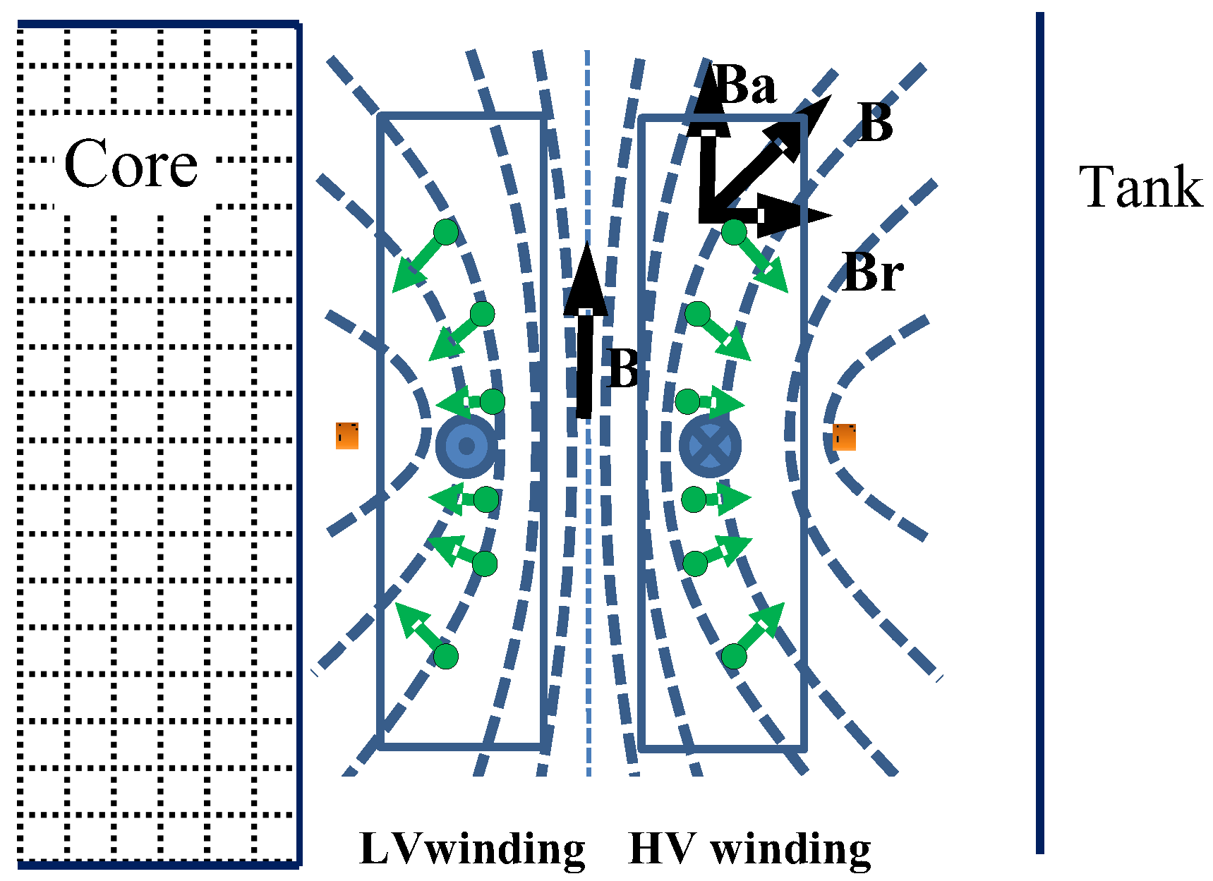
2.3. The Density of Leakage Magnetic Flux and Short-Circuit Force

The radial and axial components of the magnetic flux density are ex-pressed as follows [32]:
B r = A ϕ z , B ϕ = 0 , B z = 1 r r A ϕ z
where B r , B ϕ , and B z are directional components of the flux density of B (T) in cylindrical coordinates.
The short-circuit forces in the winding of a power transformer are estimated by the transient currents and the magnetic flux density. The force on the power transformer is expressed by the Lorentz force as follows [33]:
d F = i d l × B
F = v J ϕ ϕ × B r r + B z z d v = F r r + F z z
where J ϕ is the ϕ -directional short-circuit current density, and ϕ , r , and z are unit vectors in cylindrical coordinates, respectively. dν represents the incremental volume element.
As a short-circuit fault occurs in a transformer, the resulting forces change over time due to the transient nature of the current and the evolving magnetic flux and can be expressed as follows [34,35,36]:
F t = F m 1 2 + e 2 R L t 2 e R L t cos w t + 1 2 cos 2 w t
The density of leakage magnetic flux and the short-circuit forces in a power transformer are illustrated in Figure 1. The radial forces exert pressure on the insulating materials, which can lead to their breakdown or deformation. This damage compromises the transformer’s dielectric strength and can lead to electrical failures [32,36]. It can also lead to misalignment, loosening, and even permanent damage to the core and windings. The axial component of the short-circuit forces may cause the windings to compress or elongate, leading to bending or buckling of the winding structure [37,38].

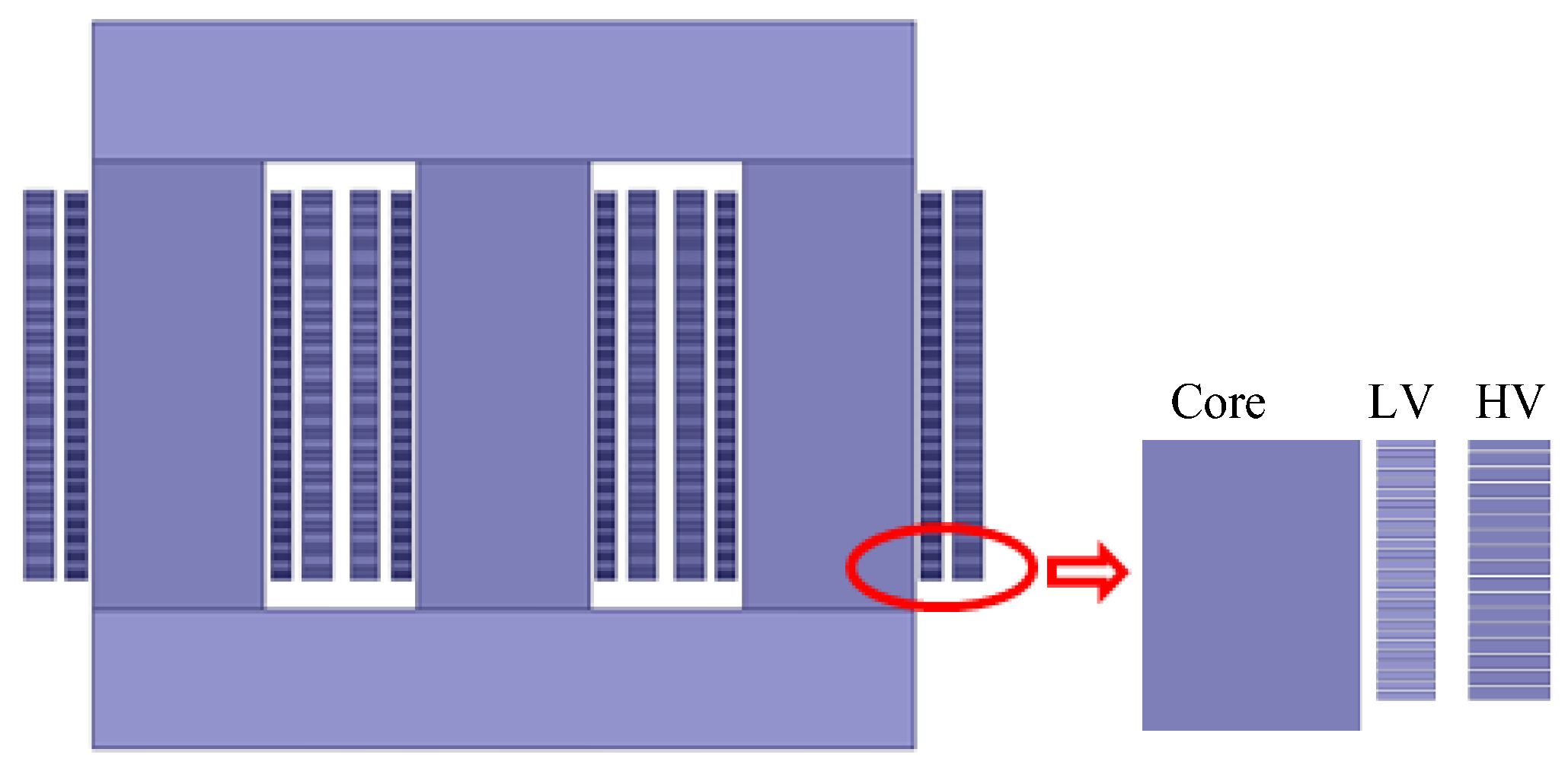
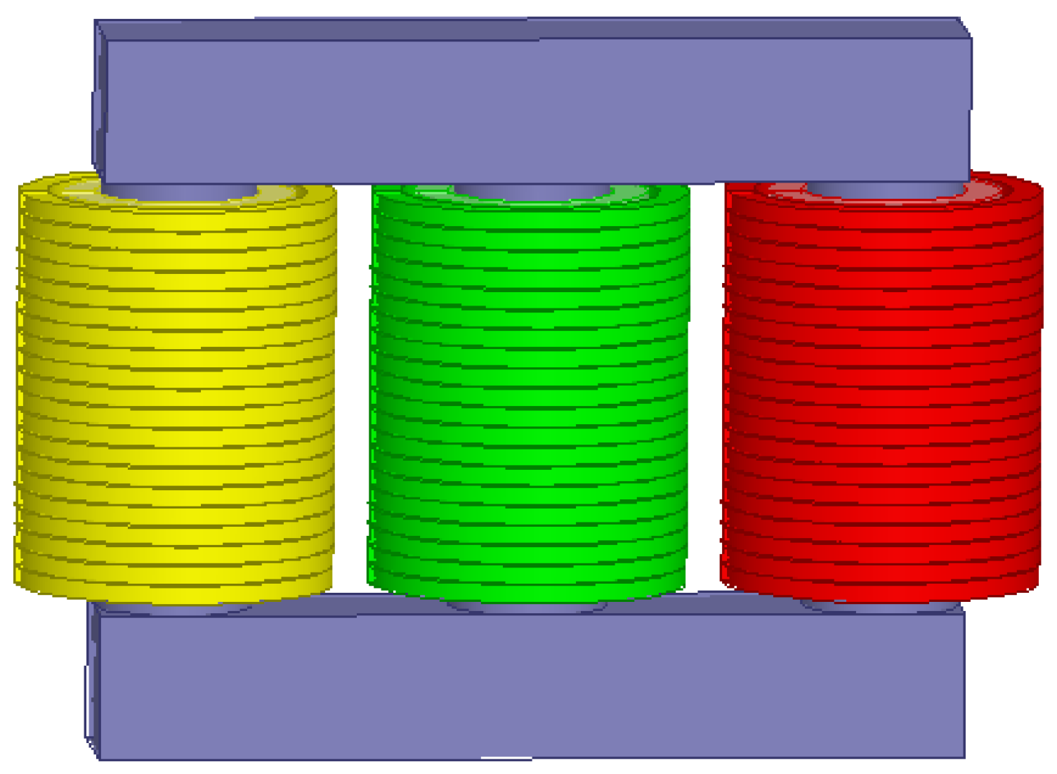
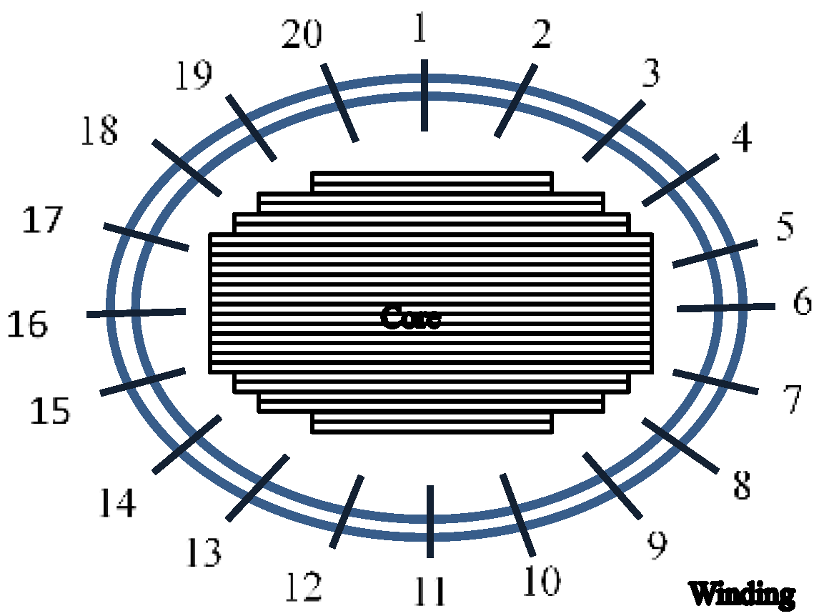
3. Transformer Model

In this paper, a three-phase core-type transformer has been studied. The specifications of the investigated power transformer, along with the data used in the FEM analysis, are given in Table 1. Characteristics of insulation system the 40 MVA transformer and equivalent circuit parameters for the 40 MVA transformer are given in Table 2 and Table 3. The HV windings consist of 70 discs, which are equally divided into two parallel sections. The LV windings are configured as a single spiral. Figure 2 presents the 2D model of the three-phase transformer under study. In this model, the LV winding, which is situated close to the core, is divided into 108 sections, while the HV winding, positioned farther from the core, is divided into 70 discs in two parallel sections. The 2D model can be employed to accurately calculate the radial and axial forces on the windings. However, to determine the distribution of radial forces on individual discs more precisely, a 3D model is required. While the 3D model offers a detailed analysis, it is significantly more complex and demands a high-performance computer and substantial processing time to achieve the same level of accuracy as the 2D model. To manage these computational challenges, the HV and LV windings in the 3D model are simplified by dividing each into 20 sections. Figure 3 illustrates the 3D model of the three-phase transformer under study.
To simplify the calculation process, several reasonable simplifications and assumptions are applied, as detailed in [38]. This includes ignoring the influence of circulating and eddy currents, assuming even distribution of current density and balanced ampere-turns distribution, and assuming all field parameters to vary as sinusoidal wave over time, regardless of the high-order harmonics.

4. Results and Discussion

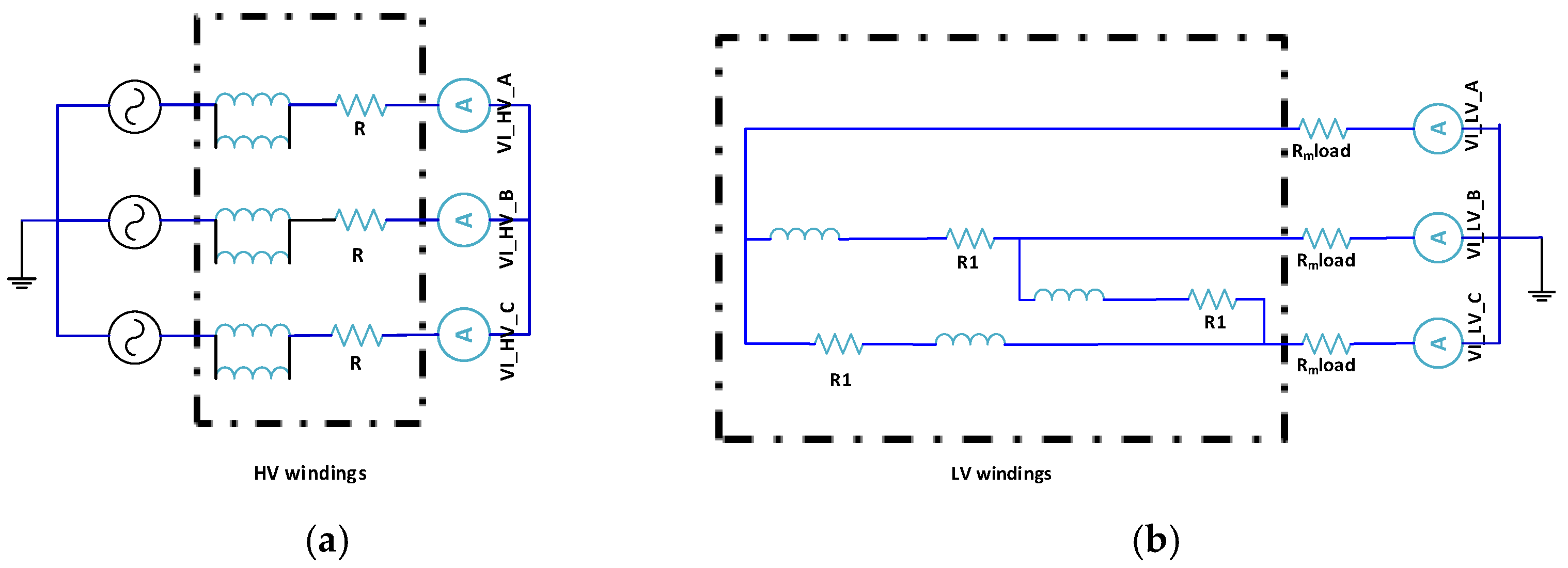
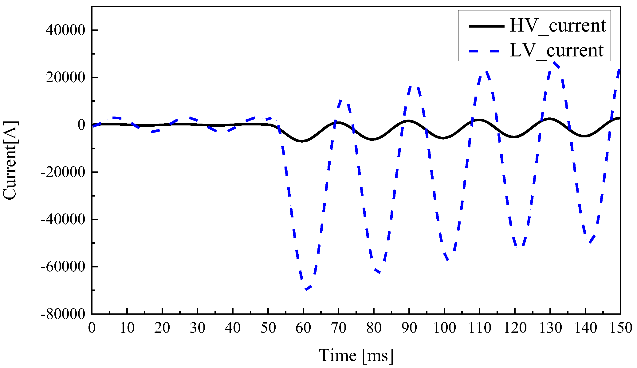
4.1. Short-Circuit Current of Three-Phase Transformer

The three-phase short-circuit condition was implemented on the transformer LV side using Maxwell Circuit Edit, as depicted in Figure 4. The initial phase angle of phase-A is set to 0 degrees. The critical short-circuit fault occurs when the terminal voltage of phase-A is at its zero crossing [39,40]. To simulate this scenario, the short-circuit condition is applied at 50 ms after the start of the analysis. This specific timing ensures that the short-circuit fault coincides with phase-A’s voltage being zero, which is considered the most severe condition for the transformer [35,41,42].
Figure 5 depicts that the maximum overshooting of the line currents for the HV and LV windings are 6963.43 A and 70,411.12 A, respectively, occurring at 59.6 ms. Comparing the analysis data obtained from the finite element software with the numerical data obtained from Formula (5) [31] as illustrated in Table 4 shows a close alignment. This agreement confirms the effectiveness of the FEA model and calculation method used in this study.

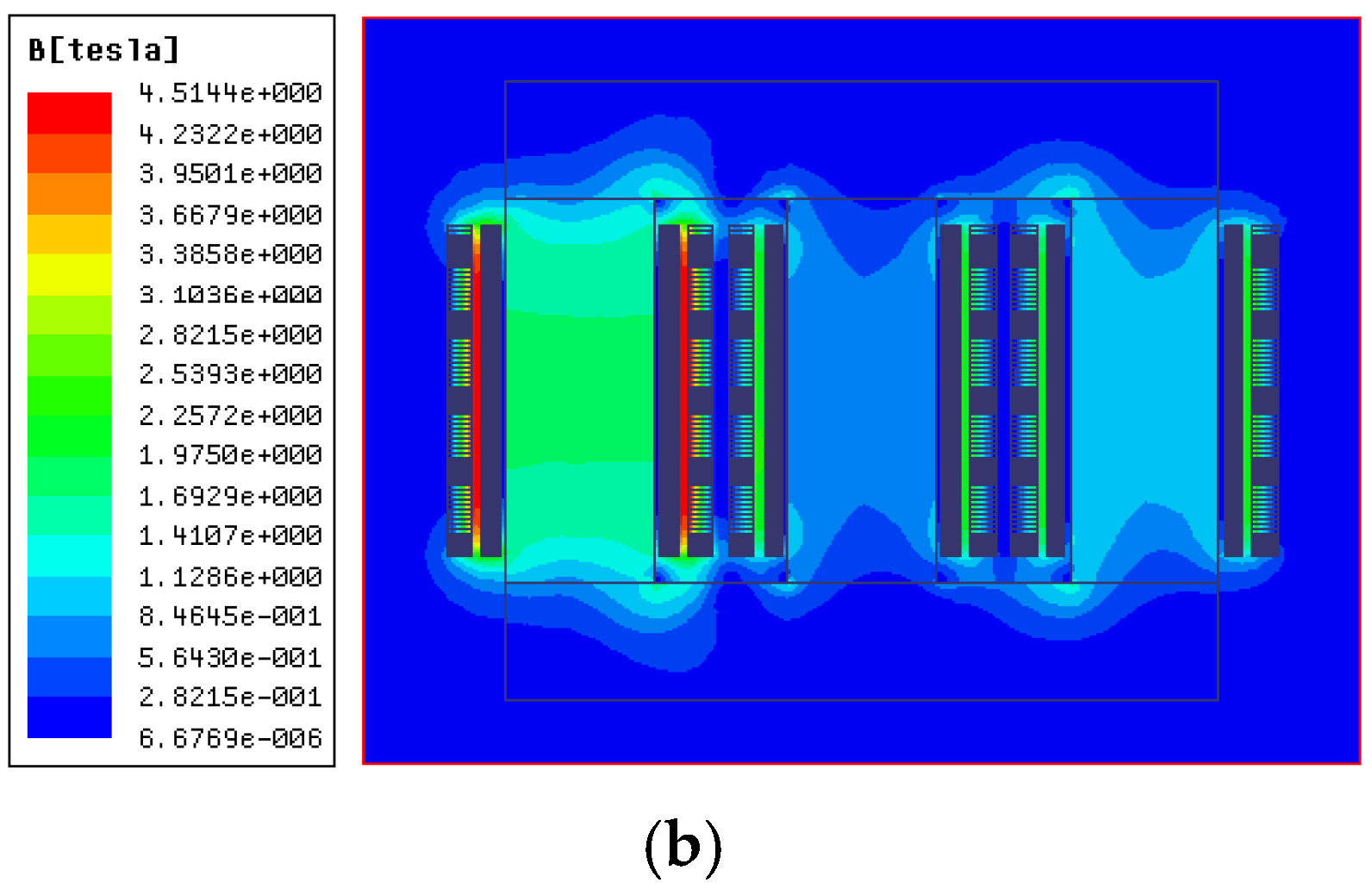
4.2. Magnetic Flux Density

The finite element software ANSYS Maxwell is utilized to simulate both the normal and short-circuit states of a power transformer. Figure 6a illustrates the distribution of magnetic flux density under normal operating conditions, while Figure 6b depicts the distribution during a short-circuit fault. Notably, the normal-state magnetic flux density exhibits a radially symmetric pattern with a maximum of approximately 1.9021 T, smoothly decaying to lower magnitudes down to 3.1186 × 10⁻⁶ T away from the core, reflecting a uniform field distribution. In contrast, the short-circuit state shows a drastically intensified magnetic field with a peak value of 4.5144 T, 2.37 times higher than normal, featuring pronounced asymmetry: the flux density near the inner core window where windings reside is significantly higher than that in outer regions, attributed to the interaction between transient short-circuit currents and the core’s geometry. This result aligns with the Lorentz force law as the enhanced flux density in the inner core directly correlates with stronger radial and axial forces on windings, providing critical insights for analyzing winding stresses and optimizing short-circuit withstand designs.

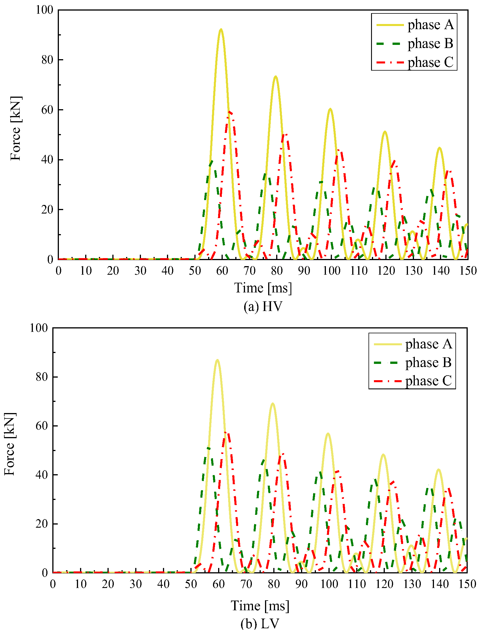
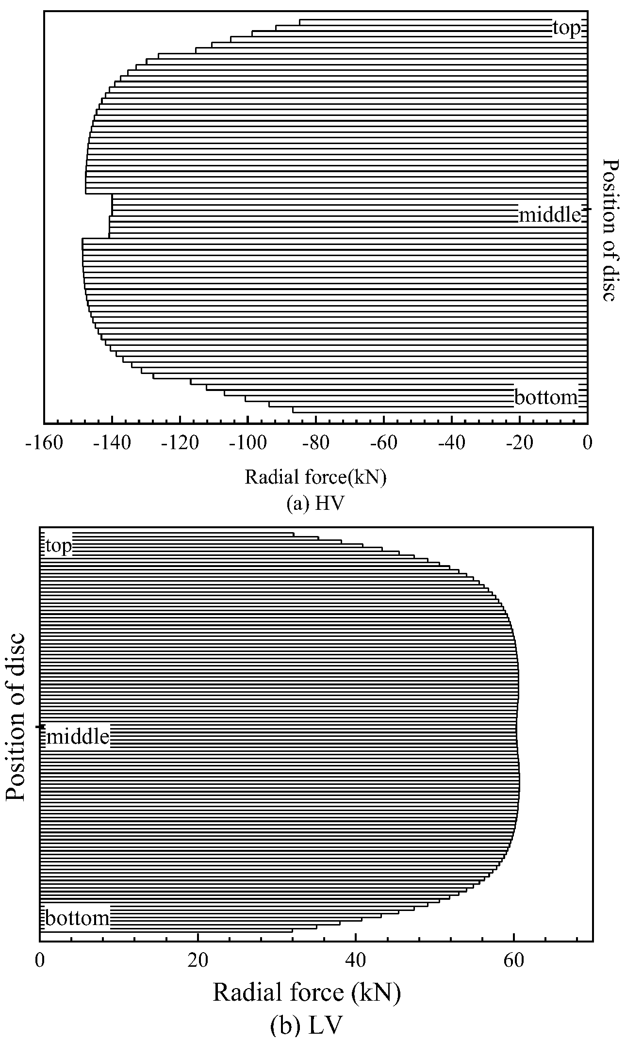
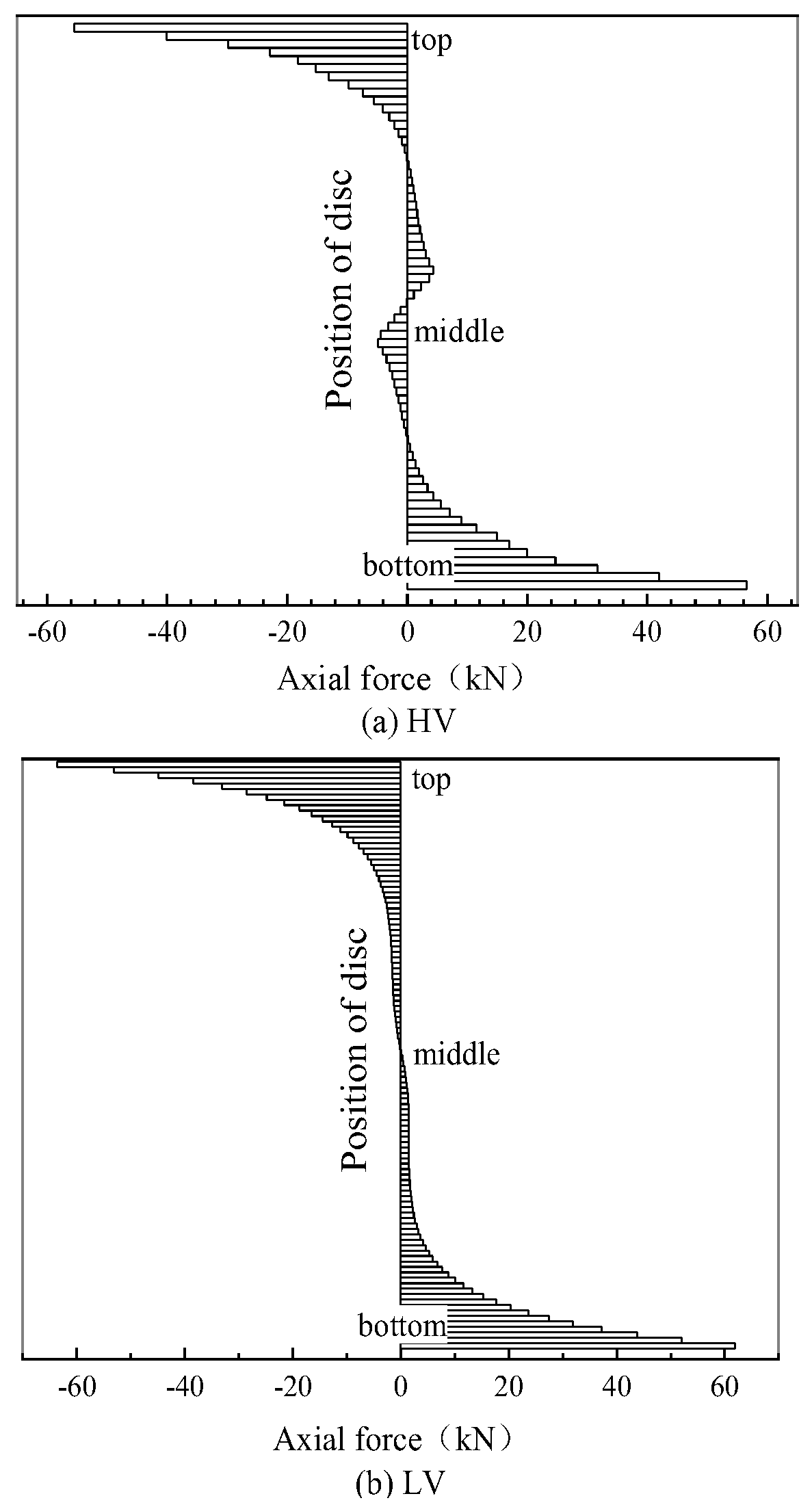
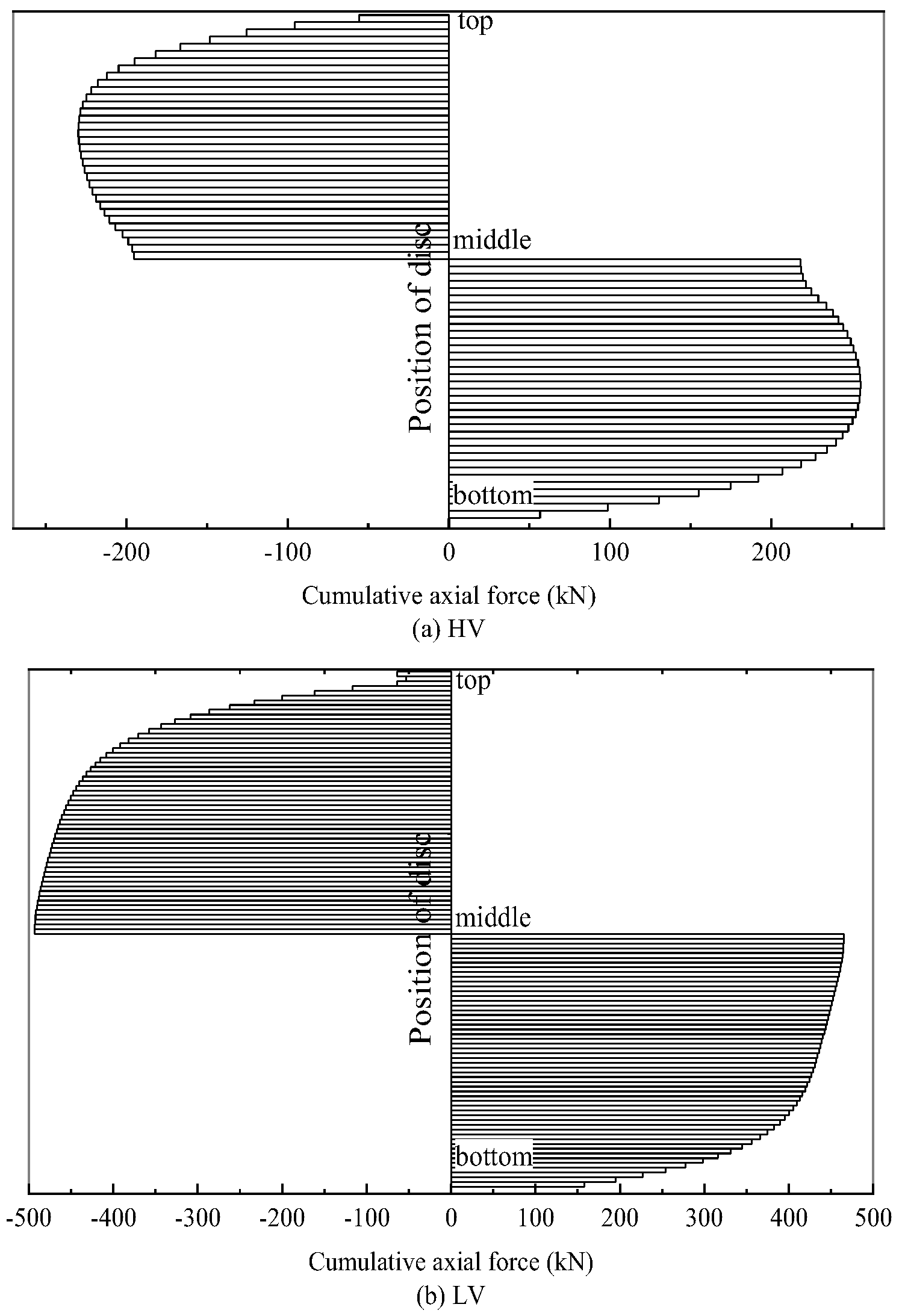
4.3. Electromagnetic Force

The computation of short-circuit forces in the transformer is based on the interaction of leakage flux and currents. To illustrate a consistent force distribution across all discs, the forces acting on the first disc are analyzed first as an example. Figure 7 displays the force curves on the first disc over time. The force curve exhibits a rapid decay after the initial short-circuit event at 50 ms. Due to the influence of other phases and asymmetry in the transformer core, the short-circuit forces acting on positions inside and outside the core window of the same winding are not equal. Figure 8 illustrates these differences, demonstrating that the forces inside the core window are greater than those outside. Therefore, this study focuses on analyzing the short-circuit forces specifically at positions inside the core window using a 2D model.
The radial forces on the HV and LV windings are illustrated in Figure 9. In these figures, forces directed radially towards the core are considered positive, while those directed towards the tank side are considered negative. Figure 9a depicts the forces on the HV windings, showing that they experience tensile forces. The forces on the middle discs are greater than those on the edge discs. Figure 9b displays the forces on the LV windings, which are compressive. Similar to the HV windings, the forces on the middle discs of the LV winding are also greater than those on the edge discs. The average radial force on the HV winding is 135.97 kN, while the average radial force on the LV winding is 89.15 kN.
Figure 10 provides a top view of the winding and core of phase-A, divided into 20 points. Figure 11 illustrates the radial forces at points 1 through 20 on both the HV and LV windings. It can be observed that the radial forces are highest on the parts of the windings located inside the core window. Specifically, the radial forces exhibit a non-uniform distribution where points 1 to 10 on the HV winding (corresponding to the inner core window region) show significantly higher values, with mid-winding points peaking at 140.735 kN compared to 85.688 kN at the edges (points 11 to 20). This trend aligns with the Lorentz force principle as inner core window positions experience stronger magnetic flux density interactions due to their proximity to the core and asymmetric magnetic field distribution during short circuits. For the LV winding, the radial forces (compressive) follow a similar pattern, with inner points registering 32.022 kN at the edges and 60.312 kN at mid-winding positions, confirming that core-adjacent regions bear the highest mechanical stress. The average radial force on the HV winding (135.97 kN) and LV winding (89.15 kN) further highlights the inner core window as a critical stress concentration area, underscoring the need for reinforced design considerations in these regions to withstand short-circuit forces.
The axial forces exerted on the HV and LV windings are depicted in Figure 12. The force directed towards the top of the windings along the axial direction is considered positive, while the force directed towards the bottom of the windings along the axial direction is considered negative. The results show that the axial force reaches its maximum value on the edge discs and decreases to zero at the middle discs, indicating that the axial force acts as a vertically compressive force on the windings. The average axial force is 7.95 kN for the HV winding and 8.87 kN for the LV winding. Table 5 presents the analyzed values of short-circuit forces on the windings of phase-A.
In addition to the direct axial force, each disc also experiences axial forces exerted by the adjacent discs, resulting in a cumulative force, as illustrated in Figure 13. The cumulative forces reach their maximum value in the middle of the HV and LV windings. This indicates that, in a balanced winding system, the total axial force on each winding sums to zero.

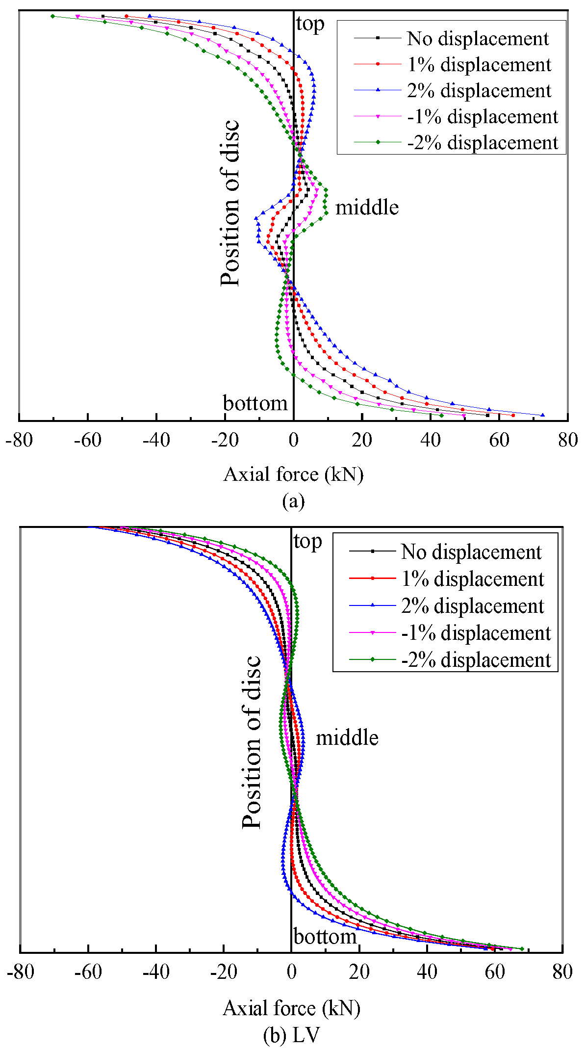
4.4. Winding Displacement

Transformer winding displacement may occur due to manufacturing inaccuracies, earthquakes, and during transportation, leading to an asymmetrical winding system. As a result, the axial forces on the windings, especially the cumulative forces, change. Consequently, the total axial force on each winding is no longer zero, resulting in an unbalanced winding system. To analyze this situation, four different HV winding displacements, ±1% and ±2% of the winding length, are modeled using FEA. As shown in Figure 14, the results indicate that these displacements have a minimal impact on the LV winding axial force distribution, while the impact on the HV axial force is observable.
Figure 15 illustrates the cumulative axial forces on the HV and LV windings of phase-A with a 1% displacement condition. The results show a general tendency for the axial forces to increase the relative displacement between the HV and LV windings.
It is important to note that acceptable values for magnetic flux density, short-circuit current, and electromagnetic forces vary depending on the transformer’s application and relevant design standards. Based on engineering practice, safety regulations, and typical design tolerances for power transformers, the magnetic flux density generally ranges from 1.4 to 1.8 Tesla. The short-circuit current is determined by the system voltage, fault level, and fault duration. Transformer windings must be mechanically designed to withstand both axial and radial electromagnetic forces resulting from short-circuit conditions and are typically tested to ensure they can endure the most severe fault scenarios.

5. Conclusions

This paper employs the finite element method to analyze the short-circuit condition of a 110 kV three-phase core type transformer. Both 2D and 3D models have been developed to accurately calculate the magnetic flux density, short-circuit current, and electromagnetic forces. The consistency between the analysis data and numerical results of the short-circuit current validates the effectiveness of the finite element model and calculation method. Considering the influence of other phases and the asymmetry of the core, it is observed that the forces inside the core window are greater than those outside. The paper also considers the physical displacement of windings, which can occur due to manufacturing defects, careless transportation, or earthquakes. During a short-circuit event, the maximum line currents in the HV and LV windings are recorded at 6963.43 A and 70,411.12 A, respectively. The average radial force exerted on the HV winding is 135.97 kN, while that on the LV winding is 89.15 kN. Additionally, the average axial forces are measured at 7.95 kN for the HV winding and 8.87 kN for the LV winding. It is noted that any physical displacement of the windings significantly alters the axial forces, leading to an unbalanced winding system where the total axial force on each winding is no longer zero. The obtained results provide valuable information that can aid in enhancing the design and reliability of power transformers without the need to perform the costly short-circuit capability test.

Author Contributions

Methodology, J.W. and X.C.; Formal analysis, J.W.; Investigation, J.H., X.C. and T.T.; Resources, J.H.; Data curation, X.C. and C.Y.; Writing—original draft, J.W.; Writing—review & editing, A.A.-S. All authors have read and agreed to the published version of the manuscript.

Funding

This research received no external funding.

Data Availability Statement

The original contributions presented in this study are included in the article. Further inquiries can be directed to the corresponding author.

Conflicts of Interest

Authors Junchi He and Tian Tian were employed by the State Grid Lianyungang Power Supply Company. Author Xiaohan Chen was employed by the State Grid Langfang Electric Power Company. The remaining authors declare that the research was conducted in the absence of any commercial or financial relationships that could be construed as a potential conflict of interest.

References

  1. Hameed, K.R.; Suraiji, A.L.; Hanfesh, A.O. Comparative the effect of distribution transformer coil shape on electromagnetic forces and their distribution using the fem. Open Eng. 2024, 14, 20220503. [Google Scholar] [CrossRef]
  2. Dawood, K.; Komurgoz, G.; Isik, F. Investigating the effect of axial displacement of transformer winding on the electromagnetic forces. In Proceedings of the 2020 7th International Conference on Electrical and Electronics Engineering (ICEEE), Antalya, Turkey, 14–16 April 2020; IEEE: Los Alamitos, CA, USA; pp. 360–364. [Google Scholar]
  3. Bigdeli, M.; Azizian, D.; Gharehpetian, G.B. Detection of probability of occurrence, type and severity of faults in transformer using frequency response analysis based numerical indices. Measurement 2021, 168, 108322. [Google Scholar] [CrossRef]
  4. Andrade, A.F.; Costa, E.G.; Souza, J.P.; Andrade, F.L.; Araujo, J.F. Evaluation of computational models for electromagnetic force calculation in transformer windings using finite-element method. Int. J. Electr. Power Energy Syst. 2024, 156, 109744. [Google Scholar] [CrossRef]
  5. Dawood, K.; Komurgoz, G.; Isik, F. Computation of the axial and radial forces in the windings of the power transformer. In Proceedings of the 2019 4th International Conference on Power Electronics and their Applications (ICPEA), Elazig, Turkey, 25–27 September 2019; IEEE: Los Alamitos, CA, USA; pp. 1–6. [Google Scholar]
  6. Rao, T.M.; Mitra, S.; Pramanik, S. A novel estimation methodology for multi-resonance equivalent inductance of transformer winding for inter-turn short-circuit fault detection. Electr. Power Syst. Res. 2024, 231, 110359. [Google Scholar] [CrossRef]
  7. Moradzadeh, A.; Moayyed, H.; Mohammadi-Ivatloo, B.; Ghareh-petian, G.B.; Aguiar, A.P. Turn-to-turn short circuit fault localization in transformer winding via image processing and deep learning method. IEEE Trans. Ind. Inform. 2022, 18, 4417–4426. [Google Scholar] [CrossRef]
  8. Cheng, Q.; Zhao, Z.; Tang, C.; Qian, G.; Islam, S. Diagnostic of transformer winding deformation fault types using continuous wavelet transform of pulse response. Measurement 2019, 140, 197–206. [Google Scholar] [CrossRef]
  9. Zhang, S.; Chen, H.; Tang, J.; Zhang, W.; Zang, T.; Xiao, X. Fault location based on voltage measurement at secondary side of low-voltage transformer in distribution network. IEEE Trans. Instrum. Meas. 2022, 71, 1–12. [Google Scholar] [CrossRef]
  10. Akhmetov, Y.; Nurmanova, V.; Bagheri, M.; Zollanvari, A.; Gharehpetian, G.B. A new diagnostic technique for reliable decision-making on transformer fra data in interturn short-circuit condition. IEEE Trans. Ind. Inform. 2021, 17, 3020–3031. [Google Scholar] [CrossRef]
  11. Ahmadzadeh-Shooshtari, B.; Rezaei-Zare, A. Advanced transformer differential protection under gic conditions. IEEE Trans. Power Deliv. 2022, 37, 1433–1444. [Google Scholar] [CrossRef]
  12. IEC 60076-5:2006; Power Transformers—Part 5: Ability to Withstand Short-Circuit. International Electrotechnical Commission: Geneva, Switzerland, 2006.
  13. IEEE C57.164-2021; IEEE Guide for Establishing Short-Circuit Withstand Capabilities of Liquid-Filled Power Transformers, Regulators, and Reac-tors. IEEE Power and Energy Society: Piscataway, NJ, USA, 2021.
  14. Hashemnia, N.; Abu-Siada, A.; Islam, S. Improved Power Transformer Winding Fault Detection using FRA Diagnostics—Part 1: Axial Displacement Simulation. IEEE Trans. Dielectr. Electr. Insul. 2015, 22, 556–563. [Google Scholar] [CrossRef]
  15. Hashemnia, N.; Abu-Siada, A.; Islam, S. Improved Power Transformer Winding Fault Detection using FRA Diagnostics—Part 2: Radial Deformation Simulation. IEEE Trans. Dielectr. Electr. Insul. 2015, 22, 564–570. [Google Scholar] [CrossRef]
  16. Zhao, Y.; Chen, W.; Jin, M.; Wen, T.; Xue, J.; Zhang, Q.; Chen, M. Short-circuit electromagnetic force distribution characteristics in transformer winding transposition structures. IEEE Trans. Magn. 2020, 56, 1–8. [Google Scholar] [CrossRef]
  17. Tarimoradi, H.; Karami, H.; Gharehpetian, G.B.; Tenbohlen, S. Sensitivity analysis of different components of transfer function for detection and classification of type, location and extent of transformer faults. Measurement 2022, 187, 110292. [Google Scholar] [CrossRef]
  18. Dawood, K.; Komurgoz, G.; Isik, F. Effect of tapping position on the electromagnetic forces of the tap-winding transformer. J. Electr. Eng. Technol. 2024, 19, 1–12. [Google Scholar] [CrossRef]
  19. Yang, W.; Pan, Y.; Qiu, Z.; Zhai, G. Electromagnetic transient model and field-circuit coupling numerical calculation of sen transformer based 25 on finite-element method. Electr. Power Syst. Res. 2023, 214, 108941. [Google Scholar] [CrossRef]
  20. Dawood, K.; Tursun, S.; Kömürgöz, G. Optimized gap positions for improved electromagnetic forces in dry-type transformer design. In Proceedings of the 2024 6th Global Power, Energy and Communication Conference (GPECOM), Budapest, Hungary, 4–7 June 2024; IEEE: Los Alamitos, CA, USA; pp. 211–215. [Google Scholar]
  21. Ahn, H.-M.; Oh, Y.-H.; Kim, J.-K.; Song, J.-S.; Hahn, S.-C. Experimental verification and finite element analysis of short-circuit electromagnetic force for dry-type transformer. IEEE Trans. Magn. 2012, 48, 819–822. [Google Scholar] [CrossRef]
  22. Jin, M.; Chen, W.; Zhao, Y.; Wen, T.; Wu, J.; Wu, X.; Zhang, Q. Coupled magnetic-structural modeling of power transformer for axial vibration analysis under short-circuit condition. IEEE Trans. Magn. 2022, 58, 1–9. [Google Scholar] [CrossRef]
  23. Salon, S.; LaMattina, B.; Sivasubramaniam, K. Comparison of assumptions in computation of short circuit forces in transformers. IEEE Trans. Magn. 2000, 36, 3521–3523. [Google Scholar] [CrossRef]
  24. Faiz, J.; Ebrahimi, B.M.; Noori, T. Three and two-dimensional finite-element computation of inrush current and short-circuit electromagnetic forces on windings of a three-phase core-type power transformer. IEEE Trans. Magn. 2008, 44, 590–597. [Google Scholar] [CrossRef]
  25. Liu, J.; Chen, S.; Wang, F.; Zhu, D.; Xu, K.; Chen, P. Theoretical Evaluation of Transformer Short-Circuit Withstand Capability and Identification Method of Winding Cumulative Deformation. IEEE Trans. Power Deliv. 2025, 1–12. [Google Scholar] [CrossRef]
  26. Wang, X.; Li, Y.; Yu, Z.; Li, P.; Xu, Z. A methodology to evaluate the radial bending stress of transformer inner windings based on the turn-to-turn model. IEEE Trans. Appl. Supercond. 2024, 34, 1–4. [Google Scholar] [CrossRef]
  27. Wang, X.; Li, Y.; Yu, Z.; Miao, Y.; Li, P.; Xu, Z. Analysis method of transformer fatigue life and damage under multiple short-circuit conditions. IEEE Trans. Appl. Supercond. 2024, 34, 1–4. [Google Scholar] [CrossRef]
  28. Ou, Q.; Luo, L.; Li, Y.; Han, R.; Peng, Y. An Improved Radial Buckling Analysis Method and Test Investigation for Power Transformer Under Short Circuit Impact. IEEE Trans. Power Deliv. 2023, 38, 2854–2863. [Google Scholar] [CrossRef]
  29. Ibrahima, S. Electromagnetic Waves 1: Maxwell’s Equations, Wave Propagation; Wiley: Hoboken, NJ, USA, 2020; p. 26. [Google Scholar]
  30. Hewitt, D.A.; Sundeep, S.; Wang, J.; Griffo, A. High frequency modeling of electric machines using finite element analysis derived data. IEEE Trans. Ind. Electron. 2024, 71, 1432–1442. [Google Scholar] [CrossRef]
  31. John, C.; Aaron, C. Transformer protection, in: Power System Protection: Fundamentals and Applications; IEEE: Los Alamitos, CA, USA, 2022; pp. 185–235. [Google Scholar]
  32. Li, Y.; Xu, Q.; Lu, Y. Electromagnetic force analysis of a power transformer under the short-circuit condition. IEEE Trans. Appl. Supercond. 2021, 31, 1–3. [Google Scholar] [CrossRef]
  33. Adly, A. Computation of inrush current forces on transformer windings. IEEE Trans. Magn. 2001, 37, 2855–2857. [Google Scholar] [CrossRef]
  34. Mikhak-Beyranvand, M.; Rezaeealam, B.; Faiz, J.; Rezaei-Zare, A. Impacts of ferroresonance and inrush current forces on transformer windings. IET Electr. Power Appl. 2019, 13, 914–921. [Google Scholar] [CrossRef]
  35. Xian, R.; Wang, L.; Zhang, B.; Li, J.; Xian, R.; Li, J. Identification method of interturn short circuit fault for distribution transformer based on power loss variation. IEEE Trans. Ind. Inform. 2024, 20, 2444–2454. [Google Scholar] [CrossRef]
  36. Wang, S.; Wang, S.; Zhang, N.; Yuan, D.; Qiu, H. Calculation and analysis of mechanical characteristics of transformer windings under short-circuit condition. IEEE Trans. Magn. 2019, 55, 1–4. [Google Scholar] [CrossRef]
  37. Cardenas-Cornejo, J.-J.; Ibarra-Manzano, M.-A.; Gonz’alez-Parada, A.; Castro-Sanchez, R.; Almanza-Ojeda, D.-L. Classification of inter-turn short-circuit faults in induction motors based on quaternion analysis. Measurement 2023, 222, 113680. [Google Scholar] [CrossRef]
  38. MacLeman, C. Transformer and Inductor Design Handbook; CRC Press: Boca Raton, FL, USA, 2014. [Google Scholar]
  39. Li, L.; Liu, X.; Zhu, G.; Chen, H.; Gao, S. Research of short-circuit performance of a split-winding transformer with stabilizing windings. IEEE Trans. Appl. Supercond. 2019, 29, 1–6. [Google Scholar] [CrossRef]
  40. Jurkovi’c, M.; ˇZarko, D. Calculation of current distribution in parallel-connected transformer winding sections in the case of asymmetric magnetic field during short-circuit test. Electr. Power Syst. Res. 2022, 210, 108141. [Google Scholar] [CrossRef]
  41. Mejia-Barron, A.; Valtierra-Rodriguez, M.; Granados-Lieberman, D.; Olivares-Galvan, J.C.; Escarela-Perez, R. The application of emdbased methods for diagnosis of winding faults in a transformer using transient and steady state currents. Measurement 2018, 117, 371–379. [Google Scholar] [CrossRef]
  42. Zhao, X.; Wu, G.; Yang, D.; Xu, G.; Xing, Y.; Yao, C.; Abu-Siada, A. Enhanced detection of power transformer winding faults through 3D FRA signatures and image processing techniques. Electr. Power Syst. Res. 2025, 242, 111433. [Google Scholar] [CrossRef]
Figure 1. Schematic of electromagnetic force and leakage flux distribution density distribution in concentric windings of a power transformer. (B represents the magnetic flux density, Ba represents the axial magnetic flux density, and Br represents the radial magnetic flux density).
Energies 18 03898 g001
Figure 2. Two-dimensional model of the three-phase transformer under study.
Energies 18 03898 g002
Figure 3. Three-dimensional model of the three-phase transformer under study.
Energies 18 03898 g003
Figure 4. Three-dimensional model of the three-phase transformer under study. (a) HV windings; (b) LV windings.
Energies 18 03898 g004
Figure 5. The short-circuit current of phase-A.
Energies 18 03898 g005
Figure 6. Magnetic flux density distribution under (a) normal state and (b) three-phase short-circuit state.
Energies 18 03898 g006aEnergies 18 03898 g006b
Figure 7. The short-circuit forces on (a) HV and (b) LV windings.
Energies 18 03898 g007
Figure 8. Forces exerted on phase-A of the HV windings (a) radial, (b) axial, and (c) cumulative axial.
Energies 18 03898 g008
Figure 9. Radial forces on (a) HV and (b) LV windings of phase-A.
Energies 18 03898 g009
Figure 10. Top view of the winding and core.
Energies 18 03898 g010
Figure 11. The radial forces on the top of (a) HV and (b) LV windings of phase-A.
Energies 18 03898 g011
Figure 12. Axial forces on (a) HV and (b) LV windings of phase-A.
Energies 18 03898 g012
Figure 13. Cumulative axial forces on (a) HV and (b) LV windings of phase-A.
Energies 18 03898 g013
Figure 14. The axial forces on (a) HV and (b) LV windings of phase-A with different values of HV winding displacement.
Energies 18 03898 g014
Figure 15. The cumulative axial forces on (a) HV and (b) LV windings of phase-A with 1% displacement.
Energies 18 03898 g015
Table 1. Specification of the power transformer under Ssudy.
ClassificationQuantify
PhaseThree
StructureCore type
Frequency [Hz]50
Rated Power [MVA]40
Winding configurationYN, dll
Primary/secondary turns [Turn]200/1200
Voltage rating [kV]110/10.5
Current rating [A]209.95/1269.84
Distance of 1st/2nd row taps to yoke [mm]187/226
Distance of HV/LV winding to upper yoke [mm]106/75
Distance of HV/LV winding to lower yoke [mm]86/55
Core cross-section diameter [mm]560
Insulated core cross-section diameter [mm]579
Inner diameter of HV/LV winding/taps [mm]826/613/1071
Table 2. Characteristics of insulation system for the 40 MVA transformer.
Mineral OilValue
Dielectric Breakdown [kV]30/85
Relative Permittivity at 25 °C2.1/2.5
Viscosity at 0, 40, 100 C [mm2·s−1]<76, 3/16, 2/2.5
Pour Flash Fire Point [°C]−30/−60, 100/170, 110/185
Density at 20 °C [kg·m3]0.83/0.89
Thermal Conductivity [W.m−1·K−1]0.11/0.16
Expansion Coefficient [10−4·K−1]7/9
Electrical Conductivity [S·m−1]1.5 × 10⁻¹⁰
Kraft PaperValue
Relative Permittivity at 25 °C4.4
Electrical Conductivity [S· m−1]24 × 10−15
Table 3. Equivalent circuit parameters for the 40 MVA transformer.
ParametersHV LV
Ls [µH]10 10.5
Rs [Ω]1 0.25
Csw [pF]393.4 127.67
Gsw [µS]196.7 63.835
Co [pF]61.192 115.53
Co [µS]30.596 57.765
CHL [pF] 89.283
GµS [µS] 44.65
Table 4. Analysis and numerical values of phase-A maximum short-circuit current.
HV Winding (A)LV Winding (A)
Analysis data6963.4370,411.12
Numerical data6971.7670,269.87
Table 5. The short-circuit forces on windings of phase-A.
HV Winding (A)LV Winding (A)
EdgesMiddleEdgesMiddle
Axial force (kN)56.0500.06362.8050.096
Radial force (kN)85.688140.73532.02260.312
Total force (kN)102.391140.73570.49860.313
Disclaimer/Publisher’s Note: The statements, opinions and data contained in all publications are solely those of the individual author(s) and contributor(s) and not of MDPI and/or the editor(s). MDPI and/or the editor(s) disclaim responsibility for any injury to people or property resulting from any ideas, methods, instructions or products referred to in the content.

