Abstract
This paper presents a comprehensive study of torsional stick–slip vibrations in rotary drilling systems through a comparison between two lumped parameter models with differing complexity: a simple two-degree-of-freedom (2-DOF) model and a complex high-degree-of-freedom (high-DOF) model. The two models are developed under identical boundary conditions and consider an identical nonlinear friction torque dynamic involving the Stribeck effect and dry friction phenomena. The high-DOF model is calculated with the Finite Element Method (FEM) to enable accurate simulation of the dynamic behavior of the drill string and accurate representation of wave propagation, energy build-up, and torque response. Field data obtained from an Algerian oil well with Measurement While Drilling (MWD) equipment are used to guide modeling and determine simulations. According to the findings, the FEM-based high-DOF model demonstrates better performance in simulating basic stick–slip dynamics, such as drill bit velocity oscillation, nonlinear friction torque formation, and transient bit-to-surface contacts. On the other hand, the 2-DOF model is not able to represent these effects accurately and can lead to inappropriate control actions and mitigation of vibration severity. This study highlights the importance of robust model fidelity in building reliable real-time rotary drilling control systems. From the performance difference measurement between low-resolution and high-resolution models, the findings offer valuable insights to optimize drilling efficiency further, minimize non-productive time (NPT), and improve the rate of penetration (ROP). This contribution points to the need for using high-fidelity models, such as FEM-based models, in facilitating smart and adaptive well control strategies in modern petroleum drilling engineering.
1. Introduction
Rotary drilling remains the centerpiece of oil and gas drilling, but one of its longest-standing problems has been managing drill string vibrations. Such vibrations, driven by advanced downhole dynamics such as fluctuating weight on bit (WOB), variable torque, and unpredictable rock–bit interactions, can potentially result in early equipment failure, drill bit wear, and monumental loss in the rate of penetration (ROP) [1,2,3]. Among the three main vibration modes, axial, lateral, and torsional vibrations, stick–slip phenomena are the most destructive and prevalent under field conditions [4,5]. Stick–slip is a nonlinear oscillating phenomenon in which the drill bit toggles between sticking (zero rotation) and slipping (high acceleration), normally to angular velocities more than the surface input speed [6]. The phenomenon causes rigorous dynamic loads to propagate along the drill string, which affects structural integrity and reduces the efficiency of drilling systems.
Many researchers have been increasingly resorting to dynamic modeling methods to better understand and mitigate these vibrations. Particularly, lumped parameter models have proven useful due to their computational ease and ability to approximate key torsional dynamics. Early studies proposed simplified models equating the drill string to a torsional pendulum system [7,8]. For instance, Moharrami et al. in [8] modeled the bottom hole assembly (BHA) as a lumped mass and the drill pipe as a torsional spring, providing the basis for time-domain simulations. Choe et al. in [9] examined the top drive torque-velocity interaction and proposed a convergent dynamic system at nominal angular velocities. Such models, while of some utility, were typically limited to low degrees of freedom (2-DOF or 3-DOF) to allow for robust control design.
Numerous recent studies have gradually increased model complexity to enhance fidelity. On the one hand, tens or hundreds of degrees-of-freedom models have been built. Kreuzer and Rideout (2023) in [10] employed a 200-DOF model to investigate torsional wave propagation and resonance effects. Such high-order models, however, have seldom been contrasted with low-order models under the same conditions, and their influence on reliability and controller robustness, particularly for real-time implementation, remains poorly understood. On the other hand, Xue (2020) in [11] proposed the 2-DOF model to variations in drill string length, but the influence of this simplified model on control robustness was not fully examined. Later, Wiktorski (2021) in [12] proposed 3-DOF models to analyze the influence of WOB variation, system stiffness, and velocity on torsional stability; their results are strictly limited to the model simplification and cannot be projected to large-scale drilling systems. Aarsnes et al. (2022) in [13] presented a 2-DOF lumped model for torsional oscillation control algorithm-based suppression. The suppression robustness depends strongly on model complexity; therefore, there is no guarantee that such controllers can provide good results for operational rotary drilling systems.
In addition to maximizing DOF, researchers have also explored various other means of improving robustness, including observer-based controllers, gain-scheduled PID tuning, model predictive control (MPC), and adaptive filtering algorithms [14,15,16]. These strategies are typically implemented and tested on extremely simplified models, and their generality and stability when applied in actual drilling operations continue to be poorly understood. Moreover, Yan et al. (2023) in [17] discussed the effect of the static and dynamic friction coefficient obtained from a simplified 2-DOF model on stick–slip vibration characteristics of the drill string and how it can affect the designed PID controller. They provided a good insight into the effect of model parameters on the system’s characteristics, but they only discussed low-DOF models.
From another side, ongoing recent advancements further push these frontiers: Zhang et al. (2021) in [18] investigated wellbore stability in anisotropic shale formations using polyaxial strength criteria to design best drilling parameters, and Fan et al. (2025) in [19] offered a poroelastic solution for semipermeable boreholes with emphasis placed on the impact of semipermeability and material anisotropy on wellbore stability. In ground pressure control, Gao et al. (2021, 2024) in [20,21] have discussed reservoir fracturing with horizontal fracture planes and graded fracturing for multi-hard rock strata, respectively, to weaken rock strength and improve mining conditions. Great efforts have also been made to improve drill string dynamics: Liu et al. (2022) in [22] established an axial–lateral–torsion coupling (ALTC) nonlinear vibration model for ultra-HPHT curved wells; Moharrami et al. (2024) in [23] performed a numerical analysis of stick–slip vibration, with a focus on the rotary table’s influence; Xie et al. (2023) in [24] designed a dynamic model of a novel parallel anchoring system for improving drilling stability; Ma and Yao (2025) in [25] built a Rayleigh rotor model for gun drill rods, with evident unstable speed intervals presented; Xue et al. (2025) in [26] designed a nonlinear dynamic model under axial excitation, with high-frequency impacts having the potential to reduce vibration damage; and She et al. (2025) in [27] studied the effect of torsional impact tools on stick–slip vibration, with potential shown in suppression. Despite such sophisticated models and control schemes, the process of extrapolating from simple laboratory setups to the reality of full-scale, true-world drilling operations is still an open challenge for generalized validity and robustness of performance.
This study fills this gap by comparing low-DOF and high-DOF lumped parameter models, both simulated under identical boundary conditions and with an integrated unified nonlinear friction torque model that includes the Stribeck effect and dry friction characteristics. The aim is not just to prove that increased DOF results in improved dynamics, which is inevitable, but to quantify to what extent model precision influences robustness and reliability on real-time torsional vibration. This study is guided by the following questions:
- Up to what extent can model complexity (in terms of DOF) affect realistic replication of stick–slip vibrations’ dynamics?
- How do model fidelity problems affect torsional vibration dynamics, particularly between drilling phases?
In addition, we propose an integrated simulation approach linking a low-order system and a high-fidelity model for field applications. Through performance evaluation across different drilling phases, this paper provides practical recommendations in model choice for drilling system simulation. To ensure that the solutions developed are firmly grounded in real-world operational conditions, this research uses field data collected from an exploration well drilled in an Algerian petroleum field. MWD sensors were deployed at various points along the drill string to record a range of dynamic values, including torque on bit, RPM, lateral and axial vibrations, and weight on bit. These field measurements not only serve to validate the dynamic behavior predicted by the simulation models but also highlight the intricacy of stick–slip torsional vibrations as observed in real drilling operations. The use of actual downhole data ensures that the comparative study between low- and high-degree-of-freedom (DOF) models is representative and can be applied under industrial drilling conditions.
In addition to its mechanical significance, the accurate modeling of stick–slip vibrations’ dynamics has direct implications for petroleum engineering optimization, as it enables better control over drilling parameters such as rotational speed, weight on bit, and input energy. Improved control strategies are correlated with a higher rate of penetration (ROP), reduced non-productive time (NPT), and minimum specific energy of drilling, all of which are desirable for minimizing operating expenses and realizing maximum recovery efficiency in fossil energy systems. This work, therefore, not only advances drill string dynamics modeling but also promotes improved energy-efficient drilling practices integral to modern petroleum drilling engineering.
The rest of this manuscript is organized as follows: Section 2 shows the field MWD data of stick–slip vibrations in the studied petroleum field; this data is used as a guide for developed models and simulation scenarios. Section 3 details the lumped model’s mathematical development. Section 4 presents the simulation results for different drilling phases and scenarios. Section 5 provides a detailed discussion. This study concludes with key findings and recommendations for future research.
2. Stick–Slip Vibrations’ Dynamic Based on Petroleum Field Data
In this section, Measurement While Drilling (MWD) data acquired from an oil well located in an Algerian petroleum field is analyzed to investigate the dynamics of stick–slip vibrations. Sensors were installed at two locations along the drill string: the first position, located immediately above the drill bit, and the second, situated at the top of the bottom hole assembly (BHA).
Downhole sensors have accelerometers to measure axial and lateral vibrations, while rotational speed sensors and torque sensors are used to estimate torsional vibration, including stick–slip effects. The data gathered by such MWD tools are then transmitted to the surface when the drilling is finished to provide valuable real-time information regarding the dynamic status of the drill string versus time and depth.
Figure 1 presents the recorded logs as a function of time (in hours). From left to right, the tracks include the following: time, torque (in lbf·ft) and weight on bit (WOB, in tons), flow rate (in L/min), standpipe pressure (SPP, in psi), block position (in meters), rotational speed (RPM: minimum, mean, maximum, and root mean square), lateral vibrations at position 1 (maximum and RMS), lateral vibrations at position 2 (maximum and RMS), axial vibrations at position 1 (minimum and maximum), axial vibrations at position 2 (minimum and maximum), rate of penetration (ROP, in meters per hour), and measured depth (MD, in meters).
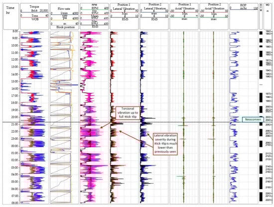
Figure 1.
Measurement While Drilling of torsional, lateral, and axial vibrations from petroleum field well in Algeria.
Data analysis indicates that the rotary drilling system exhibits coupled torsional and lateral vibrations. However, it was observed that the severity of lateral vibrations during stick–slip events is notably lower than that of lateral vibrations occurring independently. As a result, this study primarily focuses on modeling stick–slip vibrations based on actual field measurements.
To further understand torsional behavior, a subsequent data acquisition was conducted two days later in the same well, as shown in Figure 2. This figure includes, from left to right, time (in hours), torque and WOB, RPM values (minimum, mean, maximum, and RMS), and ROP. At a specific time, the variation in RPM at the first position (near the drill bit) was plotted as a function of elapsed time. The results display distinct fluctuations in drill bit angular velocity, alternating between sticking and slipping phases. These oscillations negatively affect the rate of penetration and contribute to increased non-productive time.
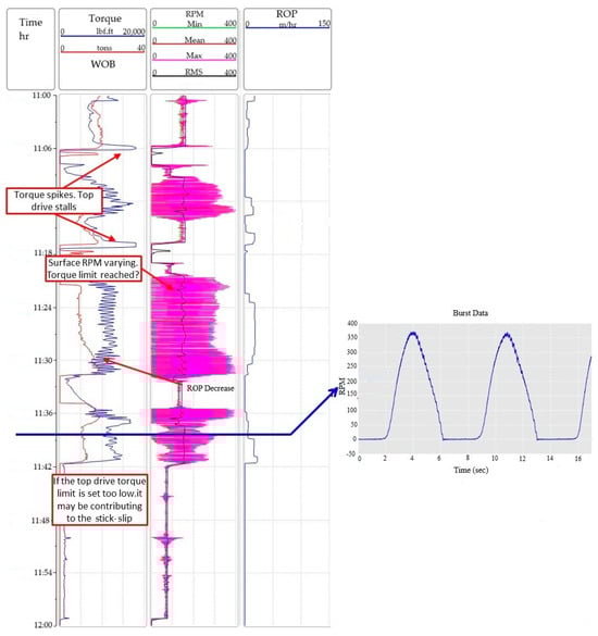
Figure 2.
Measurement While Drilling of stick–slip vibrational dynamic in petroleum well in Algerian oil field.
The measured ROP from this data represents the dynamic ROP measured as a function of time and as a function of depth. The designed model primarily aimed to capture the rotational dynamics of the drill string. Since this dynamic is strongly related to ROP, the latter was used as an input to our models and was not calculated as an output.
To develop effective control strategies for mitigating these vibrations, it is essential first to evaluate the mathematical models that represent stick–slip vibrations’ dynamics and assess their reliability in replicating field behavior. Therefore, the objective of the following section is to present two lumped parameter models, a low-degree-of-freedom model and a high-degree-of-freedom model, and to analyze how increasing model complexity improves fidelity in capturing the observed stick–slip vibrations’ dynamics from field measurements.
3. Mathematical Models
To comprehensively investigate the dynamic characteristics of the drill string in the wellbore, constructing a nonlinear and dependable model capable of approximating the accurate drill string dynamics encountered in the field becomes an essential imperative. The main objective of modeling drill string behavior is to mitigate undesirable vibrations manifesting during the drilling process, which subsequently stimulate harmful effects on drilling equipment [28]. In this regard, many investigative studies have been conducted to model and control the drill string [14,29,30,31]. These research works provide many approaches, including purely simulation-based models and those synergistically merged with experimental assessments; these approaches collectively facilitate the enhanced comprehension of the principal determinants of high-frequency severe stick–slip vibrations.
To obtain reliable drill string dynamics, a dual-pronged approach must be adopted. First, a dependable complex model will be developed to represent the composite assembly of drill pipes and the BHA. Afterward, selecting an appropriate friction model assumes significance in capturing the intricate nonlinear behavior characterizing the rock–bit interaction [31,32,33]. This section is focused on an in-depth examination of torsional vibrations and their intensified manifestation of stick–slips. In pursuit of this objective, the drill string dynamics were modeled by the analogy of a torsional pendulum, which serves as a framework to clarify its behavior under varying drilling field conditions.
Both low-DOF and high-DOF lumped models were subjected to uniform rotation by an identical top drive system, ensuring a consistent power input for comparative analysis of their dynamic responses. Therefore, the torque is dependent on the angular velocity. Correspondingly, uniform boundary conditions were applied to both models at the top drive extremity.
This study, in exploring the nonlinear dynamics of drill strings subjected to stick–slip vibrations, relies on several main assumptions. Both the simplified 2-degree-of-freedom (2-DOF) model and the more complex high-DOF model are simulated under the same boundary conditions, using the same nonlinear friction torque model, which includes the Stribeck effect along with dry friction characteristics. The drill string itself is represented as a torsional pendulum system with the various components (top drive, drill pipes, and BHA) lumped as masses or rigid disks with associated torsional stiffness and damping. Particularly, for the 2-DOF model, it is assumed that the BHA weight is considerably greater than the drill pipe weight so that the BHA may be treated as a concentrated mass, and the twisting angle of the BHA is very small compared to the drill pipe. In addition, the top drive system motion can be affected by bottom hole oscillations. The gearbox of the top drive system is considered to be frictionless and massless.
The damping effect of the drilling fluid, a dominant factor for drill pipe vibration, is simulated by lumped viscous damping terms (C and Cb) in the drill string and BHA motion equations. It is pointed out that this approximate technique does not simulate the complex, non-Newtonian, viscoplastic character of the drilling fluid, a limitation of the current model in fully representing complex fluid–structure coupling [34].
3.1. The Top Drive Dynamics
An electric motor, which can be of alternating current (AC) or direct current (DC) type, supplies the torque needed to achieve the desired angular velocity of the top drive. The design of the top rotary system shown in Figure 3 is inspired by the configuration previously published by Nguyen et al. (2020) in [35] in the context of a rotary table, a concept also featured in a subsequent work [36,37].

Figure 3.
Conceptual lumped model with 2-DOF.
The top drive, shown in Figure 3, is composed of the following components: (1) an integrated electrical motor to ensure the power supply to the drill string, with the mass moment of inertia and angular position as the main characteristics of the chosen motor; (2) a gearbox with as a gear ratio; and (3) a main shaft with the mass moment of inertia and angular velocity . is the mass moment of inertia of the top drive, is the mass moment of inertia of the bit, is the equivalent viscous damping torque at the drill pipe, is the torque on the bit, is the lumped torsional stiffness coefficient of the drill pipe, and is the lumped damping coefficient of the drill pipe.
3.1.1. The Electrical Model
According to Nguyen et al. (2020) [35], the equation of motion of a DC electrical motor is given by Equation (1):
where I is the armature current, Km is a constant characterizing the motor, Rm is the armature resistance, L is the inductance, and is the input voltage; it is given by Equation (2):
where is the gear ratio, and is the desired angular velocity. The output torque at the motor shaft is calculated using Equation (3).
where is the torque to be transmitted to the gearbox and then to the main shaft.
3.1.2. The Gearbox
We incorporated a top drive gearbox to model the angular velocity of the primary shaft, either amplifying or attenuating it. Given the relationship between torque and velocity, a suitable gear ratio should be strategically chosen to yield an output velocity lower than the input. Thus, producing a substantially augmented output torque relative to the initial input torque is a design feature particularly advantageous in drilling operations [36]. We considered the gearbox configuration design to represent an integrated assembly without friction and mass, comprising a principal gear wheel and an array of pinions. The interrelation between the angular velocity of the main shaft (top drive) and the motor shaft is summarized by Equation (4), and this relationship is dependent on the chosen gear ratio .
where is the angular velocity of the electrical motor, and is the angular velocity of the main shaft in the top drive. As mentioned above, the gearbox is frictionless, which leads to a performance equal to one.
where is the torque provided to the top drive to rotate at a given angular velocity .
3.1.3. The Main Shaft
The main shaft functions as a torsional conduit to facilitate the linkage between the gearbox and the drill string. At its upper terminal, it interfaces with the main gear to acquire rotational motion, while its lower extremity is threaded into the initial component of the drill string. Within the scope of this study, the propagation of torsional vibrations, an extensively observed phenomenon within the drill string, can influence the angular velocity of the main shaft. Moreover, the main shaft is characterized by a mass moment of inertia denoted as . By summing this inertia with the electrical motor’s mass moment of inertia , the aggregated mass moment of inertia of the top drive can be deduced, as given by Equation (6).
where is the lumped mass moment of the inertia of the top drive.
3.2. The Drill String Dynamic
We derived the equations of motion for the lumped model by applying a torsional pendulum framework. The composite lumped drill string is conceptually segmented into three principal constituents: the top drive, drill pipes, and the BHA. Each component plays a crucial role in facilitating the efficacy of drilling processes by fulfilling distinct functional requirements. The top drive is tasked with dispensing rotational power; the drill pipes serve as conduits for transmitting rotational motion from the uppermost point to the lower end, and the terminal segment of the drill string, denoted as the BHA, imparts the essential axial load. To deduce the equations of motion governing the model, a foundational principle is suggested where the top drive is subjected to an input torque, thereby inducing a predetermined angular velocity. Then, this rotational motion is propagated along the drill pipes to reach the BHA. By applying the principles of motion for the torsional pendulum, the resultant equation of motion is expressed by Equation (7):
where L is the angular momentum, and is the dynamic moment of external forces. Equation (8) gives an expression of angular momentum:
where is a unit vector; substituting Equation (8) into Equation (7), Equation (9) is obtained:
In a torsional pendulum comprising disks, the dynamic equilibrium covering viscous damping forces and element rigidity is considered. This analytical examination yields the equation of motion characterizing the behavior of the ith element, as elucidated by Equation (10):
where C is the lumped viscous damping coefficient, k is the lumped torsional stiffness coefficient, and i − 1, i, and i + 1 are the previous, current, and next elements, respectively.
Expression (10) is the principal equation of motion capturing the dynamics of a rotating torsional pendulum within a general framework. In the specific context of a drilling system, an outcome can be drawn through analogy, giving rise to the equation of motion governing the uppermost disk. This disk symbolizes the top drive component and obeys the mathematical formulation given by Equation (11):
The amount refers to the lumped viscous damping torque inside the top drive system. is the lumped torsional stiffness coefficient of the drill pipe; it is calculated by Equation (12):
where is the lumped damping coefficient used to express the effect of drilling mud next to drill pipe walls, G is the shear modulus of the drill pipe, ldp is the drill pipe length, D is the outer diameter of the drill pipe, and d is the inner diameter. We obtained a transfer function of this system by performing Laplace transformation for frequency-domain analysis of the simulation under the Simulink MATLAB 2025a environment. By setting ωtd and ωb equal to and , respectively, Equation (11) becomes
By applying linear Laplace transformation, Equation (13) becomes
The amount is the difference in angular velocities of two successive disks. Taking , Equation (14) can be rewritten as
By expressing as a function of remaining terms, the equation of motion of the top drive is given by Equation (16):
The model primarily considers the motion of the drilling fluid through its dampening action via lumped viscous damping coefficients. However, the inertial action of the flow of the drilling fluid, a significant contributor to drill string vibrations, is not explicitly dealt with in this current investigation. The results for driving torque, friction torque, and angular velocity in this paper are achieved through a combination of methods. The fundamental method is lumped parameter modeling, the complex drill string system simplified to discrete components with fixed inertial, stiffness, and damping properties. These models are then solved and analyzed numerically by a Finite Element Method (FEM)-based approach to enable realistic simulations of the dynamic responses to provide the precise values for the models’ parameters.
3.3. The Friction Torque Dynamic
Given the inherent cutting action required by the drilling process, generating stick–slip vibrations is an inevitable phenomenon primarily stimulated by a distinctly nonlinear friction torque [38]. This reactive torque results from incorporating a viscous damping torque caused by the drilling fluid circulation, coupled with a nonlinear friction torque emerging at the interface between the drill bit and the wellbore. The magnitude of this nonlinear torque affecting the drill bit is subject to the influence of several parameters, including WOB, formation hardness, drill bit classification, and angular velocity magnitude. The formulation of drilling vibration models is strongly related to specifying the bit–rock interaction dynamics and selecting an appropriate friction model. In the literature, many models have been introduced for this dynamic, which offers many approximations for this interaction that can be used for drill string modeling and simulation. A notable subset of these models is based on Coulomb friction and dry friction principles, such as Karnopp’s model, which is complemented by an exponentially decaying friction term [39].
The friction torque model proposed in this study draws inspiration from the framework established by Farhangfar (2022) in [16]. This adopted model is as follows: when the drill bit’s angular velocity deviates from zero, a composite representation of the Stribeck effect and a dry friction model is invoked. Nevertheless, when the angular velocity remains null, an alternate friction model, as Han et al. (2023) established in [40], is combined with Karnopp’s model, considering distinct operational conditions. Therefore, the friction torque model’s implementation aligns with this dualistic framework as given by Equation (17):
where is the friction torque acting on the drill bit, and is the amount of external torque needed to overcome the static friction torque Tsb and rotate the drill bit; its expression is given by Equation (18):
where is the equivalent viscous damping torque at the bit, and it is given by Equation (19):
where is the lumped damping coefficient, and is the static friction torque given by Equation (20):
where is the drill bit radius, which is chosen according to the drilling phase, is the axial load or WOB, and is the Coulomb friction torque given by Equation (21):
where is the dry friction coefficient at the drill bit; it is given by Equation (22):
where and are the static and Coulomb friction coefficients, Dv is a very small positive number, and is a positive constant characterizing the decaying region. Figure 4 shows the friction torque model as given by Equation (17).

Figure 4.
Graph representing the friction torque model proposed in this study.
Figure 4 shows that when the drill bit angular velocity values are lower than the threshold and the externally transmitted torque is less than or equal to the static friction torque , the drill bit transitions into the stick phase and maintains a mobile state for a finite duration. During this finite period, the torque delivered to the drill bit through the drill string progressively accumulates until it surpasses the static friction torque threshold. The generated nonlinear dynamics when the cumulated energy is released transition the drill bit into the slip phase, which stimulates a complex dynamic that affects the drill bit, the drill string, and the drilling efficiency. Such complex dynamics generate uncertainties in the lumped model, as detailed in the next subsection.
3.4. Low-DOF Lumped Model
One of the models that is used, the 2-DOF lumped model, is known to be a simplification of the complexity of drill string dynamics. However, it is deliberate that this reduced model, together with a high-DOF model, is included in this research work, focusing on determining the influence of model fidelity on the accuracy and reliability of simulating stick–slip vibrations’ dynamics, an application rigorously validated by real MWD field data. Figure 3 depicts a representative lumped model with 2-DOF. This model is formulated under specific properties: (1) The weight of the BHA is significantly greater than that of the drill pipe, and therefore, it can be considered a concentrated mass. (2) The slender nature of the drill pipes substantiates the assumption that the twisting angle of the BHA remains negligibly tiny in comparison to that exhibited by the drill pipe. (3) The motion of the top drive system can be impacted by the oscillations emerging from the bottom hole.
The drill string’s behavior is similar to a torsional pendulum characterized by a pair of degrees of freedom: one allocated to the top drive and the other reserved for the BHA and the drill bit. An integrated electrical motor furnishes the force for the drill string’s rotational motion, ensuring operation at the predefined angular velocity. Facilitating the transmission of rotational motion to the drill bit, the drill pipe is conceptually simplified as torsional stiffness represented by . The interaction between the drilling mud and the drill pipe is symbolized as a viscous damping mechanism . Rajabali et al. (2020) in [41] computed the lumped mass moment of inertia of the BHA by dividing the drill string into three distinct segments: the drill pipe, heavy-weight drill pipe, and drill collar. The summation of corresponding inertia across these segments is accomplished, with the inertia attributed to the drill pipe being divided by a factor of three.
The incremental advancement of the drilling process necessitates the successive inclusion of supplementary drill pipes while maintaining a constant length for the BHA. A procedure analogous to that demonstrated by Equations (7) through (10) is assumed to derive the equation of motion governing the BHA. Under the idea of the BHA being exposed to an externally applied driving torque, connected with the influence of a frictional torque acting on the drill bit, the equation of motion governing the BHA is obtained in Equation (23):
where is the lumped viscous damping coefficient at the BHA and drill bit, and is the external driving torque provided by the top drive through the drill pipe, and it is given by Equation (24):
The same transformation conducted in Equation (14) is also used to transform Equation (23) into Equation (25):
Simplifying Equation (25),
It can be noticed that
Therefore, the transfer function of the equation of motion for the BHA is
By assembling (16) and (28) into one system of equations, the whole model can be simulated using Equation (29):
The Simulink block of the 2-DOF lumped model is given in Figure 5.
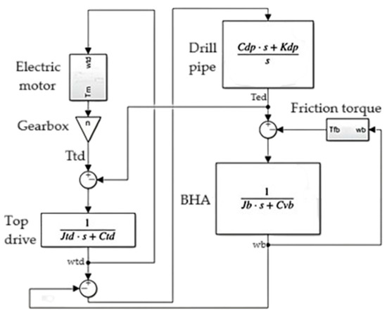
Figure 5.
Simulink block diagram of 2-DOF drill string model.
The low-DOF model, while yielding computational convenience and simplicity of implementation, suffers from important restrictions when it is employed to simulate the complex dynamics of rotary drilling systems operating under stick–slip conditions [37]. Its dynamic cannot represent the distributed stiffness and mass of the drill string, nor can it accurately simulate energy accumulation and release dynamics during stick–slip transitions. This leads to unrealistic synchronization of the angular speeds of the top drive and drill bit and underestimates the amplitude of the torsional oscillations. Due to this, vibration control methods designed with 2-DOF models might become under-tuned and collapse during actual drilling operations, where phase delay and high-frequency excitations play dominant roles. The 2-DOF model also lacks spatial resolution, making it incapable of capturing internal wave propagation, bit–rock interaction effects, or leading precursors to fatigue, which are critically necessary for real-time control and predictive maintenance.
3.5. High-DOF Lumped Model
A significant portion of lumped models involves the discretization of the drill string, often partitioning it into two or three distinct components depending on the number of disks used. The principal constituents include the top drive, drill pipe, and the BHA, each conceptually approximated as rigid disks during the development of lumped models. The accuracy of these constituent approximations necessitates adherence to boundary conditions situated at both extremities, including the drill pipe segment. A crucial boundary condition corresponds to the top drive at the upper extremity. More precisely, the derivative of angular momentum aligns with the input torque provided by the integrated electrical motor. On the other hand, the lower boundary is related to the BHA and the drill bit, and here, too, a distinctive boundary condition is necessary. In this context, the derivative of angular momentum corresponds to the disparity between the externally applied driving torque and the frictional torque elicited by the interaction between the rock and the drill bit. In specific scenarios, in-depth comprehension of the drill string’s behavior at specific positions is essential, extending beyond the upper and lower boundaries. This understanding is influential in unveiling the propagation pattern of stick–slip vibrations up to the surface. To this end, the drill string necessitates segmentation into more disks, as shown in Figure 6.
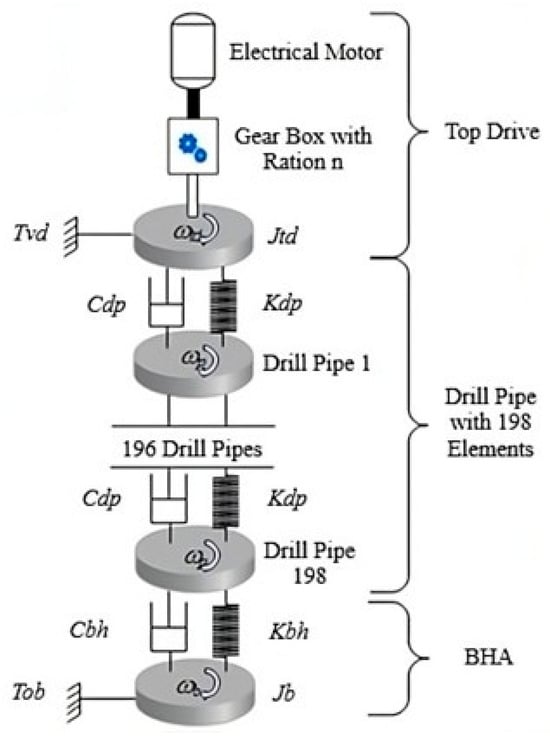
Figure 6.
Conceptual lumped model with high-DOF (200).
In this model, the drill string was discretized into 200 distinct elements, which were conceptually described as lumped mass moments of inertia analogous to 200 rigid disks. The model design resembles the configuration proposed by Kreuzer and Rideout (2023) in [10], including 198 drill pipes in addition to two fundamental components: the BHA and the top drive. The boundary conditions applied at the upper and lower disks mirror those used within the 2-DOF model. The initial rigid disk, serving as the top drive, represents a mass moment of inertia . In comparison, the concluding rigid disk, characterizing the BHA dynamics, incorporates a mass moment of inertia .
The intervening disks, characterized by mass moments of inertia, emulate the conduct of drill pipes. These elements within the drill string are interlinked by torsional springs and torsional damping , facilitating consistent interactions. Moreover, the last disk remains interconnected with the drill pipe through a torsional spring and corresponding torsional damping . The equations of motion governing this lumped model are derived by the application of the fundamental principles of dynamics to each element [42]. Equation (10), previously derived in the preceding section, summarizes the motion characteristics of a single rigid disk. Therefore, within the framework of a torsional pendulum incorporating 200-DOF, the equations of motion are presented in matrix form as given by Equation (30):
where M is the lumped mass matrix of the system; it is given by Equation (31):
where C is the damping matrix; it is given by Equation (32):
where K is the stiffness matrix; it is given by Equation (33):
where F is the vector of different external torques acting on the drill string; it is given by Equation (34):
The elements of matrices M, C, and K are calculated using Equations (35), (36) and (37), respectively:
where is the density of the drill string, is the polar second moment of area, is the drill string length, is the damping coefficient, and G is the shear modulus.
The 200-DOF model is expected to provide high-fidelity, but not necessarily in modeling drill string dynamics, which can capture localized deformation, torque oscillation, and nonlinear wave propagation along the string. This high-DOF model may allow for accurate spatial analysis, correct identification of phase shifts, and increased amplitude during stick–slip motion; however, this is at the cost of computational requirements, model complexity, and practical complications in real-time control implementation. Therefore, the trade-off between model cost and accuracy is critical: while high-DOF models are required for offline simulation, control validation, and digital twin operation, they become too heavy for embedded real-time systems unless low-order models or surrogate architectures are used. Thus, a simulation study based on MWD data is designed to compare both low- and high-DOF models and provide a deep understanding of the advantages and limitations of each of them. Current lumped parameter models largely deal with the torsional mechanical vibrations of the drill string and do not implicitly include or account for hydroacoustic effects. However, they can be significantly influential in deep boreholes and influence the overall dynamics of drilling.
Upon derivation of the equations of motion for both models, a systematic comparative analysis is conducted to discover their efficacy in reliably imitating the stick–slip phenomenon and the underlying dynamics of the drill string in response to vibrations. This process includes exploring how variations in specific drilling parameters influence stick–slip severity. Furthermore, the critical angular velocity, indicative of the threshold at which torsional vibrations appear, is assessed using both models and compared to the field data study, as discussed in Section 4.
4. Simulation Results
This section describes the simulation outcomes obtained from the lumped models formulated in Section 3. The simulation contains diverse scenarios, each characterized by distinct drilling parameters. The fidelity of reproducing the drilling process is supported by developing the drill string’s behavioral model within two distinct drilling phases. Within each phase, crucial parameters subject to manipulation involve the drill string’s length and the radius of the drill bit. In the quest to mitigate stick–slip vibrations, adjustments are directed toward the desired angular velocity and the WOB, which constitute practical candidates among the array of drilling parameters [43].
The drill string parameters in these simulation scenarios mimic the operating drilling system’s authentic attributes defined in the well where the MDW data is registered. They are similar to those used by Meddah et al. (2025) in [31] for the 2-DOF model, while Kreuzer and Rideout (2023) in [10] are referenced for the 200-DOF model. Several of these parameters exhibit sensitivity to the specific drilling phase and the well’s depth, thereby englobing characteristics such as the mass moment of inertia of the BHA and the radius of the drill bit. Conversely, a subset of parameters remains invariant throughout the simulation, including attributes such as top drive parameters and the lumped viscous damping coefficient [44].
Both models are driven by an identical top drive rotary system, although the proportional nature of the model provided dissimilarities in the mass moment of inertia associated with the top drive [37]. Table 1 summarizes the parameters used for the top drive and frictions, and their description. Table 2 and Table 3 illustrate the drill string parameters used in the case of the lumped model with 2-DOF and 200-DOF, respectively, for drilling phases 1 and 2.

Table 1.
Top drive and friction parameters.
Table 2.
Parameters of low-DOF model.
Table 3.
Parameters of high-DOF model.
The drilling system is divided into two phases depending on the borehole diameter and depth. With a 26-inch diameter (0.6604 m), the initial phase runs from the ground level (z = 0 m) to z = −500 m. The second phase shifts to a smaller diameter of 16 inches (0.4064 m) and covers the interval from z = −500 m to z = −2000 m.
4.1. Drilling Phase One
As documented by Silvestrov (2021) in [28], drill string vibrations manifest across all shallow and deep depths. Such an inescapable occurrence emphasizes the necessity of incorporating this variability within the modeling framework of drilling systems. To this end, the ongoing section focuses on analyzing the drill string dynamics within a shallow vertical well. This analysis examines two distinct scenarios: a smooth drilling mode and a rough drilling mode characterized by the stick–slip vibrations.
4.1.1. Smooth Drilling Mode
The concept of the smooth drilling mode relates to a scenario wherein the drill bit interfaces with the rock uninterruptedly without any stick–slip characteristics. By empirical observations from the field, an advised angular velocity for drilling operations has been determined to surpass the 150 revolutions per minute (rpm) threshold, corresponding to an angular velocity of 15.72 radians per second. Therefore, the designated angular velocity in smooth drilling is 20 radians per second. As for the WOB parameter, an average magnitude of 50 kN is selected to effectuate the transmission of an adequate axial load.
By established friction principles, the driving torque delivered by the top drive and subsequently transmitted via the drill pipe must manifest with a magnitude that surpasses a requisite threshold, thereby surmounting the counteracting static friction torque that obstructs the rotational motion of the drill bit. Upon successfully surpassing this frictional threshold, the driving torque will be stable and attain a consistent value identical to the Coulomb friction torque. This Coulomb friction torque describes the effective interaction between the rotating drill bit and the geological formation. During the initial drilling phase, characterized by the imposition of a 50 kN axial load, the static and Coulomb friction torques assume magnitudes of 5000 Nm and 8000 Nm, respectively. As demonstrated in Figure 7, the driving torques applied to the bit exhibit similar behavior patterns. Initially, these driving torques exhibit an ascending trend, ending by surpassing the static friction threshold. Later, they transition into a declining trajectory, stabilizing at a constant magnitude corresponding to the Coulomb friction torque.
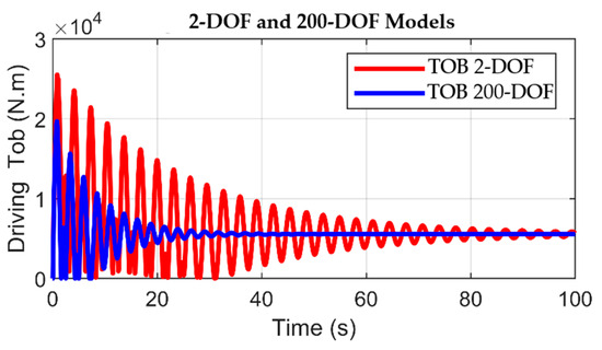
Figure 7.
Driving torque on bit in 2-DOF and 200-DOF models for smooth drilling.
Upon comparing the two driving torques depicted in Figure 7, the model with 200-DOF demonstrates enhanced stability characteristics. The 200-DOF model achieves convergence to the steady-state regime in a shorter duration of 40 s, in contrast to the 80 s interval exhibited by the 2-DOF model. The two models work in an open-loop form and, based on the inherent stability of the rotary drilling system, can converge towards a steady state following the disturbances caused by stick–slip vibrations. However, based on its energy-dissipation characteristics and numerous discrete elements along the drill string, the high-degree-of-freedom model exhibits a higher convergence rate. By comparison, the 2-DOF model limits energy dissipation to multiple locations, resulting in time-consuming stabilization. During the steady-state phase, both models attain comparability as they approach the Coulomb friction torque.
Figure 8 depicts the friction torque interaction between the rock and the drill bit. In the initial stages and throughout the non-exceedance of the static friction torque, the friction torque reflects the magnitude of the externally applied driving torque, ensuring the immobility of the drill bit during this period. Then, the friction torque ultimately transitions from the static friction torque to stabilize at the level of the Coulomb friction torque.

Figure 8.
Friction torque in 2-DOF and 200-DOF models with smooth drilling.
Comparing the two models reveals that the friction torques computed by both models exhibit similarity, an outcome attributed to the uniformity of the boundary conditions adopted at this study’s outset, including the shared imposition of consistent frictional principles. Furthermore, the friction torque profiles shown in Figure 8 follow strict linear progression, holding a constant magnitude throughout the simulation time. This characteristic indicates a smooth drilling mode characterized by the absence of vibrational perturbations. The 2-DOF model’s torque response exhibits significant non-regularities characterized by two significant oscillations. This is due to a single point of frictional interaction (as illustrated in Figure 3), whose nature induces stepwise changes in the frictional torque. However, the 200-DOF model uses 198 points of frictional discrete interaction (as illustrated in Figure 6), which makes the frictional torque less inhomogeneous along the drill string. By this token, the aggregate torque response in the 200-DOF model is much smoother, reflecting a more realistic situation of energy loss and mechanical interaction throughout the system.
The angular velocity curves, illustrated in Figure 9 and Figure 10, exhibit analogous trajectories across both model configurations. An initial transient deviation, lasting for a few seconds, becomes apparent at the onset, affecting the angular velocity of the top drive. This transient perturbation is succeeded by an interval of steady-state behavior, during which the top drive achieves the predetermined velocity in the case of the 2-DOF model (Figure 9). On the other hand, for the 200-DOF model, the top drive transitions into a steady state with a constant velocity marginally lower than the target value. The drill bit preserves a state of immobility until such time that the applied driving torque surpasses the magnitude of the static friction torque. After this juncture, the drill bit initiates rotation, exhibiting an angular velocity that exceeds the intended value before attaining stabilization and converging toward a constant threshold.
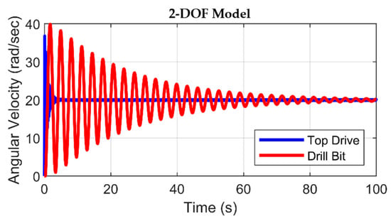
Figure 9.
Angular velocities of top drive and drill bit in 2-DOF model with smooth drilling.
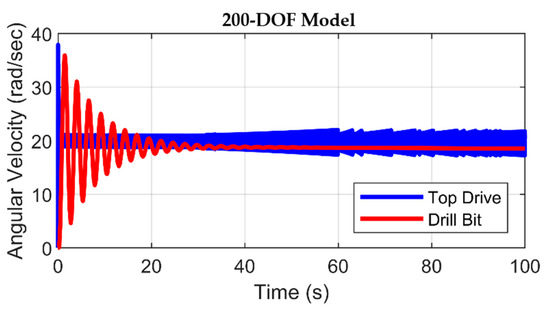
Figure 10.
Angular velocities of top drive and drill bit in 200-DOF model with smooth drilling.
The rationale underlying this behavior of the drill bit can be interpreted by the observation that applying the driving torque to the stationary bit causes the accumulation of potential energy within the torsionally deformed drill string. As the drill bit starts rotational motion, this accumulated potential energy converts into kinetic energy. The angular velocity of the top drive in Figure 10 indicates that for a higher degree of freedom, the upper part of the drill string is more sensitive to stick–slip vibrations, which increases in the top drive until t = 80 s. After this time, the angular velocity of the top drive starts decreasing and eventually stabilizes after a certain period, beyond 100 s.
4.1.2. Rough Drilling with Stick–Slip Vibrations
Drill string oscillations are notably under two principal parameters: WOB and angular velocity. Thus, to replicate the torsional vibrations within the framework of the initial drilling phase (phase 1), it becomes imperative to either reduce the intended angular velocity or amplify the WOB. Within this phase, the chosen course of action involves a reduction in the designated angular velocity. In contrast, for the subsequent drilling phase (phase 2), the elevation of the WOB is selected to induce the manifestation of stick–slip phenomena. Hence, the following simulations have been effectuated using a designated angular velocity of 5 rad/s, corresponding to 47.7 rpm, in conjunction with a WOB value of 50 kN. Figure 11 shows the results for the driving torque signals.
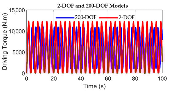
Figure 11.
Driving torque on bit in 2-DOF and 200-DOF models with rough drilling.
As depicted in Figure 11, the driving torque did not achieve a sustained equilibrium, instead oscillating between two distinct magnitudes: one equivalent to the static friction torque and the other positioned below the threshold of the Coulomb friction torque. The evolution of the driving torque is characterized by a progression composed of four distinct phases. This phase begins with an ascending segment, characterized by the stick phase, causing the drill bit to momentarily stop. After this, the stick–slip transition happens, characterized by the driving torque attaining its peak, a value that aligns with the magnitude of the static friction torque. The third phase, the descending segment, occurs when the driving torque surpasses the Coulomb friction threshold. This phase triggers the release of the drill bit, thereby inducing rapid acceleration. The fourth phase appears after the slip phase. Within this phase, the driving torque decreases below the threshold of the Coulomb friction torque, resulting in a deceleration of the drill bit until it is completely stopped. For a deeper understanding and comparison, we plotted the variation in frictional torque for 2-DOF and 200-DOF models, as given in Figure 12.
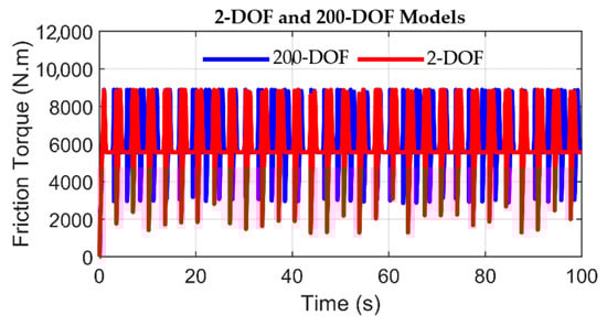
Figure 12.
Friction torque in 2-DOF and 200-DOF models with rough drilling.
Figure 12 depicts that the friction torque exhibits an oscillation pattern between three distinct magnitudes. The initial value corresponds to the static friction torque, the subsequent value aligns with the Coulomb friction torque, and the last value assumes a position below the Coulomb friction threshold. The latter value correlates with the magnitude of the driving torque upon the slip phase’s peak. This noticeable variation in friction torque magnitudes creates a consequential impact on the oscillatory behavior of the angular velocity of the drill bit, thereby giving rise to the manifestation of high-frequency stick–slip vibrations [45]. Figure 12 depicts the behaviors of frictional torque under extreme stick–slip situations. The 2-DOF model exhibits extremely high oscillations, reflecting its weak capacity to absorb energy because it has just one frictional interface. In comparison, the 200-DOF model exhibits significantly smoother torque oscillations, illustrating how the increased degrees of freedom support distributed damping and a better ability to suppress the severity of vibrations along the drill string. These graphs demonstrate the significance of model complexity in accurately capturing and suppressing torsional instability in rotary drilling systems.
Figure 13 and Figure 14 show the dynamic behavior of the drill bit under stick–slip vibrations. The angular velocity of the drill bit increases to a magnitude that is twice that of the top drive’s angular velocity. This noticeable dissimilarity is interpreted as potential energy conversion, accumulating within the drill string during the stick phase, into kinetic energy. This resulting kinetic energy increment augments the driving torque applied to the bit, thus encouraging the drill bit to attain amplified rotational velocities. Comparatively, the model characterized by 200-DOF (Figure 14) demonstrates a delicate sensitivity to the stick–slip phenomenon when contrasted with the 2-DOF model. This distinction is evident in the stick–slip severity detected by the high-DOF model. At the surface, stick–slip vibrations remain minor at the top drive.
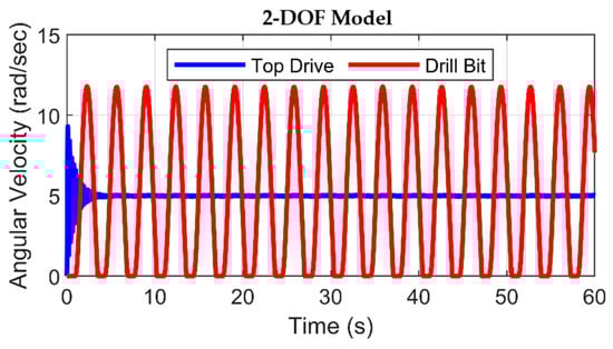
Figure 13.
Angular velocities of top drive and drill bit in 2-DOF model with rough drilling.
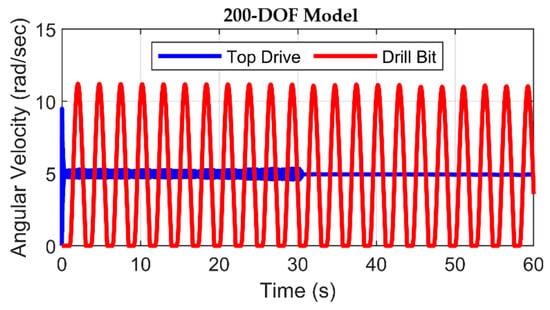
Figure 14.
Angular velocities of top drive and drill bit in 200-DOF model with rough drilling.
4.2. Drilling Phase Two
As previously explained, stick–slip vibrations remain fundamentally self-excited regardless of the specific drilling phase, with their manifestation intricately depending on the chosen drilling parameters. Therefore, to corroborate the crucial role of drilling parameters in originating stick–slip occurrences, the drilling depth was systematically augmented from 500 m to 2000 m, thereby drilling phase two. In the previous section, we considered two distinct drilling scenarios: the first characterized by smooth drilling and the second characterized by rough drilling, identified by the appearance of high-frequency stick–slip vibrational perturbations.
4.2.1. Smooth Drilling
Engaging optimal drilling velocities is a strategic approach for mitigating challenges that commonly arise during formation penetration, incorporating the mitigation of drill string vibrations. Especially in scenarios involving deep drilling within complex rock formations, adopting moderate angular velocities maintains an optimal penetration rate while concurrently mitigating the effects of drill bit vibrations. Thus, for the simulation of drilling phase 2, a required angular velocity of 124 rpm, equivalent to 13 radians per second (rad/s), has been established. Figure 15 illustrates the simulation results of smooth drilling for phase 2 with 2-DOF and 200-DOF.
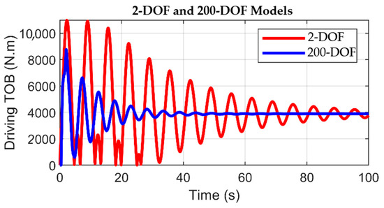
Figure 15.
Driving torque on bit in 2-DOF and 200-DOF models with smooth drilling for phase 2.
During the smooth drilling mode, the evolutions of the driving torque, as depicted in Figure 15, manifest similar patterns to those witnessed during the initial drilling phase. Starting with fluctuations, the driving torque ultimately converges toward a steady state. The 200-DOF model demonstrates faster stability in the first drilling phase. Conversely, the 2-DOF model experiences an extended transient period wherein the driving torque fails to attain a steady-state condition within the simulation duration. This issue is mainly due to the augmented drilling depth of 2000 m, which necessitates an extended duration for the cutting process to attain a state of smooth operation. The friction torque profiles, shown in Figure 16, further illuminate the distinctive behaviors between the 2-DOF and 200-DOF models. For the 2-DOF model, the friction torque mirrors the characteristics of stick–slip vibrations at the onset of the simulation, as it oscillates between the static and Coulomb friction torques during the first 20 s. In contrast, the friction torque displayed by the 200-DOF model reflects the conventional variation associated with the interaction between the drill bit and the formation in the absence of vibrational perturbations.
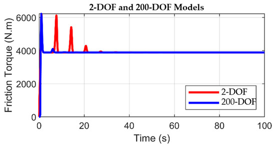
Figure 16.
Friction torque on bit in 2-DOF and 200-DOF models with smooth drilling for phase 2.
The 2-DOF model demonstrates four distinct torque fluctuations instead of the traditional two. This is because of the largeness of the vibrations and the model’s reliance on a point of frictional contact, which amplifies sudden torque response changes. Conversely, the 200-DOF model shows a more uniform torque profile because of its scattered frictional contact points along the drill string. Its spatial distribution allows energy dissipation to occur gradually and, consequently, a more stable and realistic representation of the system’s dynamic behavior. This part of the simulation phase 2 was intended to be conducted free from stick–slip vibrations. However, the observed angular velocity of the drill bit in the 2-DOF model exhibits minor fluctuations, resembling oscillatory behavior similar to vibrations.
A comprehensive interpretation of the drill bit motion, as depicted in Figure 17, can be elucidated as follows: The drill bit remains stationary until the driving torque surpasses the static friction torque. At this moment, the rotation initially starts with an increasing velocity profile. Furthermore, due to the increasing drill bit velocity, the necessary driving torque for keeping the rotation of the drill string diminishes to an approximate null value, thereby causing the sticking of the drill bit. On the other hand, once the static friction threshold is exceeded, the angular velocity of the drill bit shown in Figure 18 converges toward a steady value that falls beneath the anticipated surface velocity. This variation in angular velocity is reasonably attributed to many factors, including the inherent stiffness of the drill string, the presence of viscous forces acting on the drill pipe, and the influence of Coulomb friction dynamics. The angular velocity of the top drive diverges in the 200-DOF model at t = 80 s. This is mainly due to the sensitivity of the upper part of the drill string to stick–slip vibrations. After 80 s, the oscillation in the top drive angular velocity starts decreasing and eventually converges after a certain period beyond the simulation time.

Figure 17.
Angular velocities of top drive and drill bit in 2-DOF model with smooth drilling for phase 2.
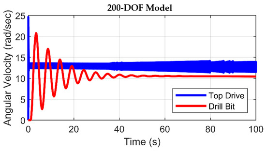
Figure 18.
Angular velocities of top drive and drill bit in 200-DOF with smooth drilling.
4.2.2. Rough Drilling with Stick–Slip Vibrations
Given the drilling depth, the onset of torsional vibrations becomes inevitable due to the exigency of either increasing the WOB or decreasing the angular velocity to maintain a desired penetration rate. So, in this simulation part, the WOB is changed from 50 kN to 100 kN whilst the desired angular velocity is fixed to 13 rad/s. As depicted in Figure 19, the driving torque applied to the bit illuminates the characteristic modulations of an input torque under the influence of stick–slip vibrations. The fluctuations are noticeable above and below the thresholds of static friction and Coulomb friction torques in the 2-DOF and 200-DOF models. In the 2-DOF model, the magnitudes of the static and Coulomb friction torque thresholds have been significantly surpassed throughout the simulation interval. Conversely, the driving torque shown by the 200-DOF model moderately surpasses the static and Coulomb friction values. This observation is coherent with established friction principles, where a substantial augmentation of the driving torque beyond the static friction torque is mandatory to induce drill bit rotation.

Figure 19.
Driving torque on bit in 2-DOF and 200-DOF models with stick–slip motion.
The friction torque profiles in Figure 20 show how the frictional contact between the drill bit and the rock switches between the static and Coulomb friction torques. Once again, it is evident that the friction torque exhibited in the 200-DOF model is characterized by a more coherent behavior than that in the 2-DOF model. This disparity can be rationalized by the observation that the friction torque values within the 200-DOF model progressively diminish from the static friction torque to a level marginally beneath the Coulomb friction torque, whereas, in the 2-DOF model, the friction torque experiences a reduction to reach a magnitude of 5000 Nm.

Figure 20.
Friction torque in 2-DOF and 200-DOF models with stick–slip motion.
The heavy rise in the WOB to 100 kN largely cancels out the overall frictional forces at the bit–rock interface. Such extreme loading conditions, even the distributed frictional dissipation offered by the 200-DOF model, will no longer be as effective, meaning model fidelity may not guarantee system stability. This is a significant limitation: under extreme axial loading, additional control methods or damping mechanisms may be required beyond heightened resolution in the model to provide robust vibration attenuation. Figure 21 and Figure 22 illustrate the drill bit velocity during stick–slip vibrations. As demonstrated in these figures, the rotational motion of the drill bit passes through two distinctive phases, namely, the stick phase and the slip phase. In the stick phase, the magnitude of the driving torque delivered to the drill bit equates to the magnitude of the friction torque elicited by the interaction between the rock and the bit.

Figure 21.
Angular velocities of top drive and drill bit in 2-DOF model with stick–slip vibrations’ dynamics.
Figure 22.
Angular velocities of top drive and drill bit in 200-DOF model with stick–slip motion.
This equality causes a stuck bit state. Subsequently, the slip phase succeeds, wherein the cumulated energy frees the bit and dissipates in all directions. Although the top drive velocity shows slight sensitivity to the vibrations, it ultimately converges toward a stable value. Both the 2-DOF and 200-DOF models effectively replicate the stick–slip phenomenon following an elevation in WOB, thus emphasizing the contextual nature of the drilling process wherein optimal drilling parameters must be determined for each distinct drilling phase. The angular velocity of the top drive in the 200-DOF diverges starting from t = 33 s. This is due to the high replicability of this model, which is because of stick–slip vibrations propagating from the drill bit to the top drive. After a certain duration, this effect decreases, and the angular velocity of the top drive eventually converges.
5. Discussion
The preceding simulations have shown that torsional vibrations manifest independently of drilling depth or phase. To develop further, these vibrations appear at any depth, which provides optimal drilling parameters. Moreover, WOB and top drive velocity are the most common drilling parameters that necessitate adjustment during transitions between drilling phases. Such adjustments are not uniquely implemented to sustain an optimal ROP but also to predict the onset of stick–slip vibrations in the drill bit.
It is important to incorporate geological parameter uncertainty into WOB and rotary speed adjustment planning. Real drilling conditions always include rock property variations, formation interfaces, and in situ stress states that are usually only partially inferred. These uncertainties directly affect the effective bit–rock interface friction and the resulting drill string dynamics. By taking into account the probabilistic distributions of these uncertain geologic parameters, adjustment strategies for WOB and rotary speed can be made robust. This allows adaptive control algorithms that can adapt to unexpected variations in formation properties, minimize the initiation and magnitude of stick–slip vibration, and optimize drilling performance under dynamic downhole conditions.
In drilling phase 1, setting the desired angular velocity above the recommended threshold incites oscillatory motion during the drill bit’s transition from static to motion, eventually attaining the desired angular velocity. In the 2-DOF model, the angular velocity of the drill bit converges precisely with that of the top drive upon stabilization, which is not correct in practice due to the friction force along the drill string. However, for the 200-DOF model, the drill bit does not align with the same velocity even at a steady state, an outcome attributable to friction forces acting along the drill string. The 200-DOF model demonstrates remarkable stability relative to the 2-DOF model, as evidenced by its swift achievement of a steady state during smooth drilling conditions and high sensitivity to stick–slip vibrations during rough drilling conditions.
For drilling phase 2, the influence of increased drilling depth is noticeable through a discrepancy between the angular velocities of the top drive and the drill bit, particularly pronounced within the 200-DOF model. Furthermore, it becomes apparent that the velocity closely approaches the critical velocity of the 2-DOF model, thereby inducing fluctuations in drill bit velocity. As previously noted, the stick–slip phenomenon is profoundly responsive to modifications in key drilling parameters, including critical WOB.
Figure 23 shows the drill bit velocity as a function of the twisting angle for the 2-DOF and the 200-DOF models. It represents an additional illustration of the simulated stick–slip vibrations occurring in drilling phase 2. The graph shows the temporal evolution of the drill bit’s angular velocity as a function of the twisting angle engendered between the top drive and the drill bit. The red line corresponds to the 2-DOF model, and the blue line corresponds to the 200-DOF model. Based on this graph, the variation can be delimited into three distinct segments: a linear region, an ascending phase, and a descending phase. The linear portion characterizes the sticking phase, where the twisting angle progressively increases while the drill bit remains stuck. The subsequent phase denotes the interval wherein the drill bit starts rotation and embarks upon the initial segment of the slip phase. In this segment, the twisting angle diminishes, facilitating the conversion of stored potential energy into kinetic energy, pushing the drill bit into high-velocity rotation. The final phase includes the latter portion of the slip phase, wherein the dissipation of transformed kinetic energy terminates, causing the driving torque to decrease and prompting the drill bit to reenter the sticking phase again. The relationship between drill bit velocity and the twisting angle exhibits a smoother trend within the 2-DOF model than in the 200-DOF model. This difference arises from the fact that, in the former, the twisting angle is measured between consecutive rigid disks. On the contrary, in 200-DOF, 198 interposing rigid disks on the twisting angle contribute to a more intricate trajectory.
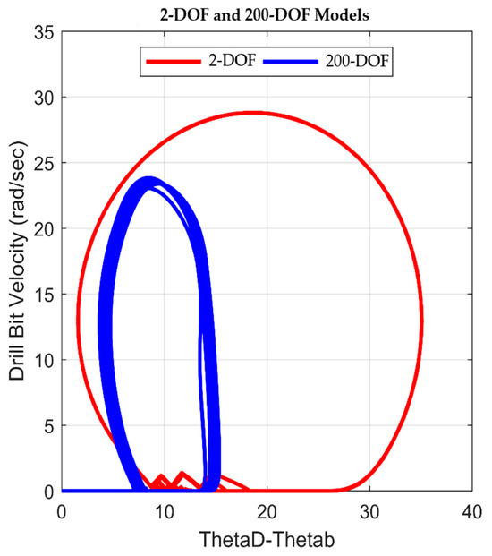
Figure 23.
Drill bit angular velocity representing stick–slip vibrations as a twisting angle between both extremities for 2-DOF and 200-DOF models.
The abrupt and instantaneous increase of the drill bit’s velocity from 0 rad/s to 25 rad/s is depicted in Figure 23 (red curve), which engenders detrimental repercussions for the structural integrity of the drill bit. The transition from the stick phase to the slip phase is accompanied by a substantial augmentation in kinetic energy, which, in turn, has the potential to induce pronounced deformations in the cutter elements. Upon analyzing empirical data collected from the studied Algerian hydrocarbon field, a characteristic pattern analogous to that illustrated in Figure 22 was observed, signifying the occurrence of stick–slip oscillations within the wellbore [46]. As recapped previously, these oscillations manifest as recurring cycles of stick and slip phases, prompting successive episodes of high-velocity contact between the drill bit and the geological formation. This interaction precipitates an initial stage of fatigue failure, characterized by the onset of microcracks [47]. As the drilling operation persists without obligatory adjustments to the pertinent parameters, the frequency of stick–slip cycles escalates, worsening the severity of fatigue-induced cracks. Hence, progression toward the second stage of fatigue failure emerges, accompanied by substantial deformations, as shown in Figure 24, obtained from the well where MWD is logged in the studied petroleum field.
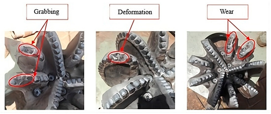
Figure 24.
Damages caused by stick–slip vibrations in Algerian hydrocarbon field [33].
The dynamic behavior predicted by the 200-DOF model, particularly regarding the severity of stick–slip, angular velocity overshoot, and trends in frictional torque, is qualitatively in agreement with such field-based damage profiles. Future work will aim to incorporate direct verification with laboratory-scale rotary drilling simulators to quantitatively validate the predictive capabilities of the proposed models. However, the current research offers a tight theoretical framework for model fidelity under only stick–slip vibration in rotary drilling systems.
While the focus of the current study is to simulate stick–slip behavior, future work should also explore the integration of a fatigue cumulative damage model [21]. Such an inclusion would allow for a direct quantitative correlation between simulated vibrations and their impacts on bit lifespan, significantly enhancing the practical utility of our dynamic models for real-time control and predictive maintenance. Future studies should also investigate the impact of geological parameter uncertainty on drill string dynamics, developing robust WOB and rotary speed adjustment strategies that account for variable downhole conditions.
Low-DOF models are widely used in industrial practice owing to their computational requirements and structural simplicity, as well as their suitability for real-time implementation in low processing capability rotary drilling systems. However, they are deficient in the fidelity required to precisely capture complex dynamic phenomena such as high-frequency stick–slip vibrations, thereby limiting predictive reliability. On the other hand, high-DOF models offer much greater accuracy by incorporating distributed mass, damping, and stiffness effects along the drill string, even though their demonstrated advantages in modeling nonlinear dynamic behavior have limited their use due to the requirements for computations and difficulty in integrating such models into real-time control systems, particularly in top drive systems. Still, due to the continuous development of computational power and the increasing demand for high-fidelity control, the application of high-DOF models is likely to extend, enabling more accurate and efficient modeling and control of torsional dynamics in actual drilling operations.
New rotary drilling systems are gradually shifting toward fully autonomous operations, where the detection, monitoring, and mitigation of undesired vibrations, such as stick–slip conditions, are managed by closed-loop control structures with minimal human interaction [48]. Effective closed-loop control depends on high-fidelity dynamic models that closely emulate actual system dynamics at low computational latency. Although high-DOF models are computationally costly, they give better description accuracy of the nonlinearities and distributed dynamics of the drill string and are therefore a prerequisite to formulate and verify strong real-time control strategies. To reduce the compromise between the fidelity of a model and computation cost, real-time implementation using reduced-order model methods or data-driven surrogate models can be resorted to. Herein, high-DOF models are employed offline to train the controller, optimize parameters, and benchmark performance, facilitating believable and adaptive control methods in operating drilling systems. Reduced-order models (ROMs), derived directly from the high-fidelity data generated by our advanced simulations, are an efficient pathway to creating lightweight surrogate models. These ROMs represent the complex drill string dynamics accurately, with significantly lower computational requirements than their full-order counterparts. Such minimized computational requirements make them ideal candidates for real-time implementation on embedded hardware to enable strong and responsive control of drilling operations without sacrificing accuracy in the results offered by high-fidelity modeling.
6. Conclusions
Torsional vibrations have emerged as one of the principal generators of the deformations and deteriorations observed in the drill bit. This study has comprehensively compared two distinct lumped models characterized by different degrees of freedom (DOF). The comparative analysis has been conducted across two distinct drilling phases, each including two distinct drilling modes. When the incorporation of operational drilling parameters is suboptimal, the tendency for vibrational occurrences at the wellbore is pronounced. A careful assessment of the driving torque temporal profiles, the friction torque, and the angular velocities of the top drive and drill bit has established that the high-DOF model offers the most coherent depiction of stick–slip oscillations. Apart from showing that the high-DOF model has more realistic output, this work illustrates how model fidelity directly affects stick–slip mitigation model’s reliability. While the low-DOF model will emulate average performance, it cannot simulate important phenomena such as energy accumulation during sticking and instantaneous jumps in velocity when slipping. Such limitations can lead to inaccurate predictions by the model in real-time applications and under-tuned controllers. The high-DOF model, on the other hand, accurately simulates the nonlinear vibration propagation of torsional vibrations, identifies initial mechanisms of fatigue, and is in good correlation with MWD data of torsional vibrations in a petroleum well. Its use can facilitate controller testing under field conditions prior to implementation, which means safer, more stable, and more economical drilling operations.
Therefore, it is highly recommended to use the high-DOF model as digital twins for offline smart controller design and verification, as well as possible real-time surrogate use through reduced-order models trained from high-fidelity simulation. Such a model can help test the reliability of the closed-loop system in the simulation and experimentally before moving forward to implementation into the rotary drilling system in the field. Further research is recommended to integrate more advanced models that explicitly incorporate the inertial influence of drilling fluid flow for enhanced accuracy in simulating drill string dynamics. Additional research must investigate the complex coupling of drill string vibrations and hydroacoustic effects for a deeper understanding of downhole dynamics. Furthermore, exploring parallel computing and hardware acceleration techniques is advised to enhance the real-time performance of these models for control applications. Future work should also explore the influence of multi-physics coupling (e.g., thermal–flow–solid) on deep-well stick–slip vibration and relate it to the embedded implementation of intelligent control algorithms using reinforcement learning.
Funding
This research received no external funding.
Data Availability Statement
The data presented in this study are not publicly available due to restrictions. However, the data can be made available from the corresponding author upon reasonable request.
Conflicts of Interest
The author declares no conflict of interest.
References
- Guan, Z.; Chen, T.; Liao, H. Theory and Technology of Drilling Engineering; Springer Nature: Singapore, 2021; ISBN 978-981-15-9327-7. [Google Scholar] [CrossRef]
- Idir, K.; Benammar, S.; Doghmane, M.-Z. Dynamic failure analysis and lifetime estimation of tool-string in rotary drilling system under torsional–axial coupled vibrations. Eng. Fail. Anal. 2022, 134, 106037. [Google Scholar] [CrossRef]
- Yu, Y.; Chen, W.; Liu, Q.; Chau, M.; Vesselinov, V.; Meehan, R. Training an automated directional drilling agent with deep reinforcement learning in a simulated environment. In Proceedings of the SPE/IADC International Drilling Conference and Exhibition, Virtual, 8–12 March 2021. SPE/IADC Paper 204105-MS. [Google Scholar] [CrossRef]
- Mohammadzadeh, M.; Shahgholi, M.; Arbabtafti, M. Vibration analysis of the fully coupled nonlinear finite element model of composite drill strings. Arch. Appl. Mech. 2020, 90, 1373–1398. [Google Scholar] [CrossRef]
- Wang, J.; Tang, S.-X.; Krstić, M. Adaptive output-feedback control of torsional vibration in offshore rotary oil drilling systems. Automatica 2020, 111, 108640. [Google Scholar] [CrossRef]
- Cheng, J.; Wu, M.; Wu, F.; Lu, C.; Chen, X.; Cao, W. Modeling and control of drill-string system with stick-slip vibrations using LPV technique. IEEE Trans. Control Syst. Technol. 2021, 29, 718–730. [Google Scholar] [CrossRef]
- De Moraes, L.P.P.; Savi, M.A. Drill-string vibration analysis considering an axial-torsional-lateral nonsmooth model. J. Sound Vib. 2019, 438, 220–237. [Google Scholar] [CrossRef]
- Moharrami, M.J.; de Almeida, C.M.; Hodjat, S. Non-linear integrated dynamic analysis of drill strings under stick-slip vibration. Appl. Ocean. Res. 2021, 108, 102521. [Google Scholar] [CrossRef]
- Choe, Y.-M.; Kim, G.-S.; Kim, I.-S.; Choe, J.-C.; Ri, K.-W.; Ho, Y.-S.; Kim, C.-H. Influence of torsional stick-slip vibration on whirl behavior in drill-string system. Geoenergy Sci. Eng. 2023, 227, 211931. [Google Scholar] [CrossRef]
- Kreuzer, D.M.G.; Rideout, G. A digital twinning methodology for vibration prediction and fatigue life prognosis of vertical oil-well drillstrings. IEEE Access 2023, 11, 62892–62905. [Google Scholar] [CrossRef]
- Xue, Q. Measurement and analysis of drillstring dynamics. In Data Analytics for Drilling Engineering; Springer: Cham, Switzerland, 2020; Chapter 5. [Google Scholar] [CrossRef]
- Wiktorski, E.; Sui, D. Investigation of model configuration parameters for stick-slip modeling. In Proceedings of the 40th International Conference on Ocean, Offshore and Arctic Engineering (OMAE 2021), Virtual, 21–30 June 2021; Volume 10. [Google Scholar] [CrossRef]
- Aarsnes, A.; Cayeux, E.; Mihai, R. Modeling and analysis of non-rotating damping subs for removing torsional vibrations in drilling. In Proceedings of the 41st International Conference on Ocean, Offshore and Arctic Engineering (OMAE 2022), Hamburg, Germany, 5–10 June 2022; Volume 10. [Google Scholar] [CrossRef]
- Riane, R.; Kidouche, M.; Illoul, R.; Doghmane, M.-Z. Unknown resistive torque estimation of a rotary drilling system based on Kalman filter. IETE J. Res. 2022, 68, 2640–2651. [Google Scholar] [CrossRef]
- Riane, R.; Doghmane, M.-Z.; Kidouche, M.; Tee, K.F.; Djezzar, S. Stick-slip vibration suppression in drill string using observer-based LQG controller. Sensors 2022, 22, 5979. [Google Scholar] [CrossRef]
- Farhangfar, A. Observer-Based Robust Model Predictive Control for a Multi-DOF Oilwell Drill String with Stick-Slip Oscillations. Ph.D. University of Calgary (Canada). Available online: https://www.proquest.com/docview/2827714313?pq-origsite=gscholar&fromopenview=true&sourcetype=Dissertations%20&%20Theses (accessed on 15 May 2025).
- Yan, B.; Tian, J.; Meng, X.; Zhang, Z. Stick–slip vibration characteristics study of the drill string based on PID controller. Energies 2023, 16, 7902. [Google Scholar] [CrossRef]
- Zhang, M.; Fan, X.; Zhang, Q.; Yang, B.; Zhao, P.; Yao, B.; Ran, J. Parametric sensitivity study of wellbore stability in transversely isotropic medium based on polyaxial strength criteria. J. Pet. Sci. Eng. 2021, 197, 108078. [Google Scholar] [CrossRef]
- Fan, Z.; Song, X.; Wang, D.; Ayasrah, M.; Li, S. Poroelastic Solutions of a Semipermeable Borehole under Nonhydrostatic In Situ Stresses within Transversely Isotropic Media. Int. J. Geomech. 2025, 25, 04024108. [Google Scholar] [CrossRef]
- Gao, R.; Kuang, T.; Meng, X.; Huo, B. Effects of Ground Fracturing with Horizontal Fracture Plane on Rock Breakage Characteristics and Mine Pressure Control. Rock Mech. Rock Eng. 2021, 54, 3229–3243. [Google Scholar] [CrossRef]
- Gao, R.; Bai, D.; Yu, B.; Tai, Y.; Meng, X.; Zhang, W. Ground fracturing of multi-strata for strong ground pressure control in extra-thick coal seams with hard roofs: Numerical simulation and case study. Eng. Fract. Mech. 2024, 303, 110129. [Google Scholar] [CrossRef]
- Liu, J.; Wang, J.; Guo, X.; Dai, L.; Zhang, C.; Zhu, H. Investigation on axial-lateral-torsion nonlinear coupling vibration model and stick-slip characteristics of drilling string in ultra-HPHT curved wells. Appl. Math. Model. 2022, 107, 182–206. [Google Scholar] [CrossRef]
- Moharrami, M.J.; Shiri, H.; Martins, C.d.A. Numerical Investigation of the Nonlinear Drill String Dynamics Under Stick–Slip Vibration. Vibration 2024, 7, 1086–1110. [Google Scholar] [CrossRef]
- Xie, M.; Li, Y.; Zhang, H.; Yang, Z.; Ren, Z.; Nie, R. Analysis of drilling vibration characteristics of anchoring system in coal mine. Sci. Rep. 2023, 13, 19236. [Google Scholar] [CrossRef]
- Ma, J.; Yao, W. Stability Analysis of Free Vibration of Gun Drill Rod. Materials 2025, 18, 1241. [Google Scholar] [CrossRef]
- Xue, Q.; Li, Y.; Jia, J.; Zhao, L. Vibration Damage Analysis of Bottom Hole Assembly Under Axial Impact Based on Dynamic Analysis. Appl. Sci. 2025, 15, 7388. [Google Scholar] [CrossRef]
- She, C.; Guo, J.; Zhang, Y. Analysis of the effects of torsional impact tools on drill string stick-slip vibration. Energy Explor. Exploit. 2025, 43, 1632–1646. [Google Scholar] [CrossRef]
- Silvestrov, I.; Bakulin, A.; Hemyari, E.; Aldawood, A.; Egorov, A. Seismic-while-drilling with a pilot signal from a downhole memory-based vibration sensor. In Proceedings of the SEG/AAPG/SEPM First International Meeting for Applied Geoscience & Energy, Denver, CO, USA, 26 September–1 October 2021. [Google Scholar] [CrossRef]
- Doghmane, M.-Z.; Kidouche, M.; Habbi, H.; Bacetti, A.; Bellahcene, B. A new decomposition strategy approach applied for a multi-stage printing system control optimization. In Proceedings of the 4th International Conference on Electrical Engineering (ICEE 2015), Boumerdes, Algeria, 13–15 December 2015; pp. 1–6. [Google Scholar] [CrossRef]
- Meddah, S.; Doghmane, M.-Z.; Tadjer, S.A.; Idir, A.; Kidouche, M.; Tee, K.F. Fractional-order PID controller design for strongly coupled high-frequency axial-torsional vibrations in drill string system. Int. J. Dyn. Control 2025, 13, 94. [Google Scholar] [CrossRef]
- Meddah, S.; Tadjer, S.A.; Idir, A.; Tee, K.F.; Doghmane, M.-Z.; Kidouche, M. Dynamic interaction analysis of coupled axial-torsional-lateral mechanical vibrations in rotary drilling systems. Struct. Durab. Health Monit. 2025, 19, 77–103. [Google Scholar] [CrossRef]
- Mendil, C.; Kidouche, M.; Doghmane, M.-Z.; Benammar, S.; Tee, K.F. Rock-bit interaction effects on high-frequency stick-slip vibration severity in rotary drilling systems. Multidiscip. Model. Mater. Struct. 2021, 17, 1007–1023. [Google Scholar] [CrossRef]
- Kessai, I.; Benammar, S.; Doghmane, M.-Z.; Tee, K.F. Drill bit deformations in rotary drilling systems under large-amplitude stick-slip vibrations. Appl. Sci. 2020, 10, 6523. [Google Scholar] [CrossRef]
- Bondarenko, A.; Islamov, S.; Mardashov, D.; Mingaleva, T. Features of oil well killing in abnormal carbonate reservoirs operating conditions. In Proceedings of the Engineering and Mining Geophysics 2019 15th Conference and Exhibition, Gelendzhik, Russia, 22–26 April 2019; Volume 2019, pp. 1–5. [Google Scholar] [CrossRef]
- Nguyen, K.-L.; Tran, Q.-T.; Andrianoely, M.-A.; Manin, L.; Baguet, S.; Dufour, R.; Mahjoub, M.; Menand, S. Non-linear rotordynamics of a drillstring in curved wells: Models and numerical techniques. Int. J. Mech. Sci. 2020, 166, 105225. [Google Scholar] [CrossRef]
- Gomar, M.; Elahifar, B. Application of digitalization in real-time analysis of drilling dynamics using along-string measurement (ASM) data along wired pipes. Energies 2022, 15, 8930. [Google Scholar] [CrossRef]
- Khulief, Y.A. Modeling of rotary drillstring vibrations: An overview. Int. J. Struct. Stab. Dyn. 2025, 2630002. [Google Scholar] [CrossRef]
- Sadeghi, A.N.; Arıkan, K.B.; Özbek, M.E. Modelling and controlling of drill string stick-slip vibrations in an oil-well drilling rig. J. Pet. Sci. Eng. 2022, 216, 110759. [Google Scholar] [CrossRef]
- Trindade, M.A. Robust evaluation of stability regions of oil-well drilling systems with uncertain bit–rock nonlinear interaction. J. Sound Vib. 2020, 483, 115481. [Google Scholar] [CrossRef]
- Han, H.; Bashir, A.; Ou, H. Friction-induced vibration of a stick–slip oscillator with random field friction modelling. Mech. Syst. Signal Process. 2023, 183, 109572. [Google Scholar] [CrossRef]
- Rajabali, F.; Moradi, H.; Vossoughi, G. Coupling analysis and control of axial and torsional vibrations in a horizontal drill string. J. Pet. Sci. Eng. 2020, 195, 107534. [Google Scholar] [CrossRef]
- Li, X.; Ma, G.; Balakumar, B. Drill-string stability and stress localization: Influence of complex delay effects and dry friction. Int. J. Non-Linear Mech. 2023, 157, 104559. [Google Scholar] [CrossRef]
- Patil, P.A.; Teodoriu, C. A comparative review of modelling and controlling torsional vibrations and experimentation using laboratory setups. J. Pet. Sci. Eng. 2013, 112, 227–238. [Google Scholar] [CrossRef]
- Samuel, R.; Schottle, G.; Gupta, G.D.B. Vibration analysis, model prediction, and avoidance: A case history. In Proceedings of the SPE/IADC Indian Drilling Technology Conference and Exhibition, Mumbai, India, 16–18 October 2006. SPE Paper 102134-MS. [Google Scholar] [CrossRef]
- Avinu, S.; Abid, K.; Teodoriu, C. Determination of the impact of drill string material on drilling vibration through simulation. In Proceedings of the SPE Oklahoma City Oil and Gas Symposium, Oklahoma City, OK, USA, 14 April 2025. SPE Paper 224363-MS. [Google Scholar] [CrossRef]
- Grant, C. BlackBox™ Dynamics Analysis Report; Internal Report; Sonatrach-Algeria: Algiers, Algeria, 2016. [Google Scholar]
- Kim, B.J.; Palazzolo, A.; Gharib, M. Drillstring simulator: A novel software model for stick–slip and bit-bounce vibrations. In Proceedings of the ASME International Mechanical Engineering Congress and Exposition (IMECE 2021), Virtual, 1–5 November 2021; Volume 7A. [Google Scholar] [CrossRef]
- Islamov, S.; Grigoriev, A.; Beloglazov, I.; Savchenkov, S.; Gudmestad, O.T. Research risk factors in monitoring well drilling—A case study using machine learning methods. Symmetry 2021, 13, 1293. [Google Scholar] [CrossRef]
Disclaimer/Publisher’s Note: The statements, opinions and data contained in all publications are solely those of the individual author(s) and contributor(s) and not of MDPI and/or the editor(s). MDPI and/or the editor(s) disclaim responsibility for any injury to people or property resulting from any ideas, methods, instructions or products referred to in the content. |
© 2025 by the author. Licensee MDPI, Basel, Switzerland. This article is an open access article distributed under the terms and conditions of the Creative Commons Attribution (CC BY) license (https://creativecommons.org/licenses/by/4.0/).