
Energy Efficiency Optimization of Air Conditioning Systems Towards Low-Carbon Cleanrooms: Review and Future Perspectives


Abstract
1. Introduction
2. Cleanroom Air Conditioning Systems
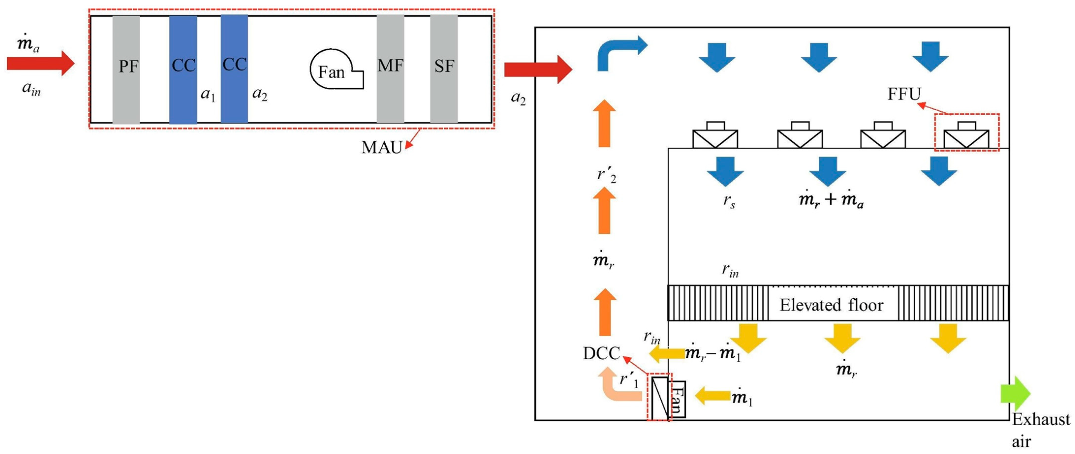
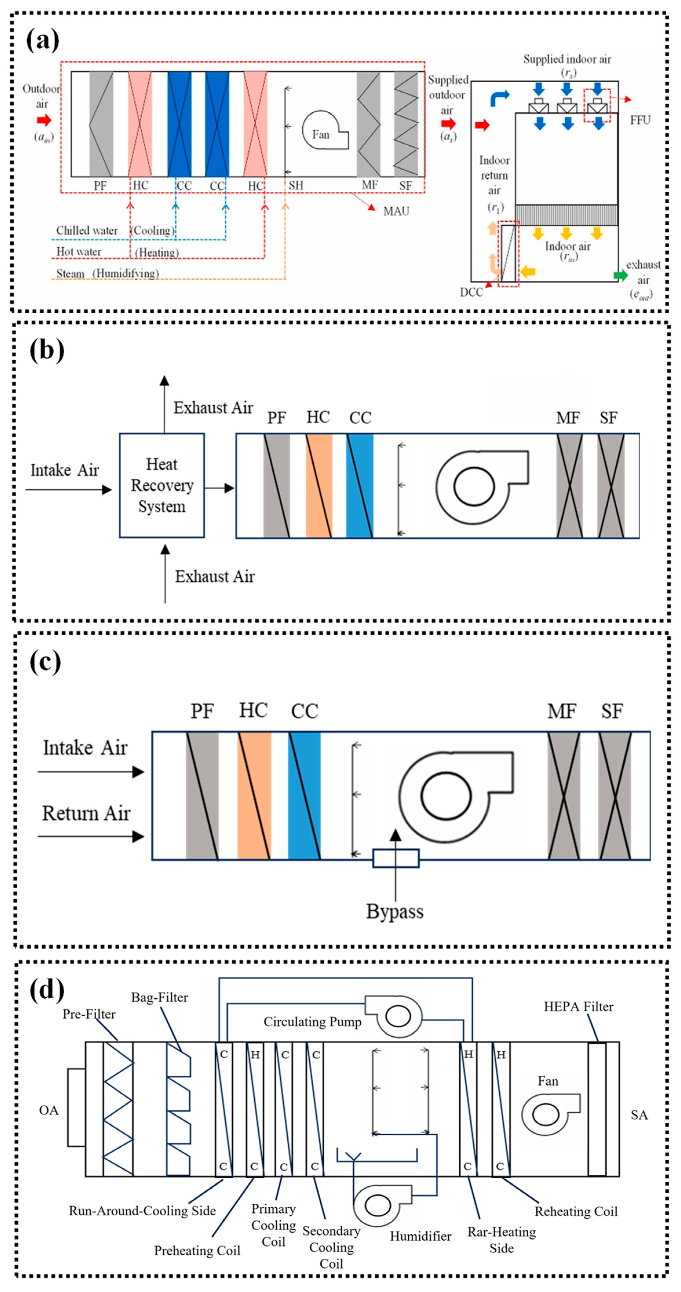
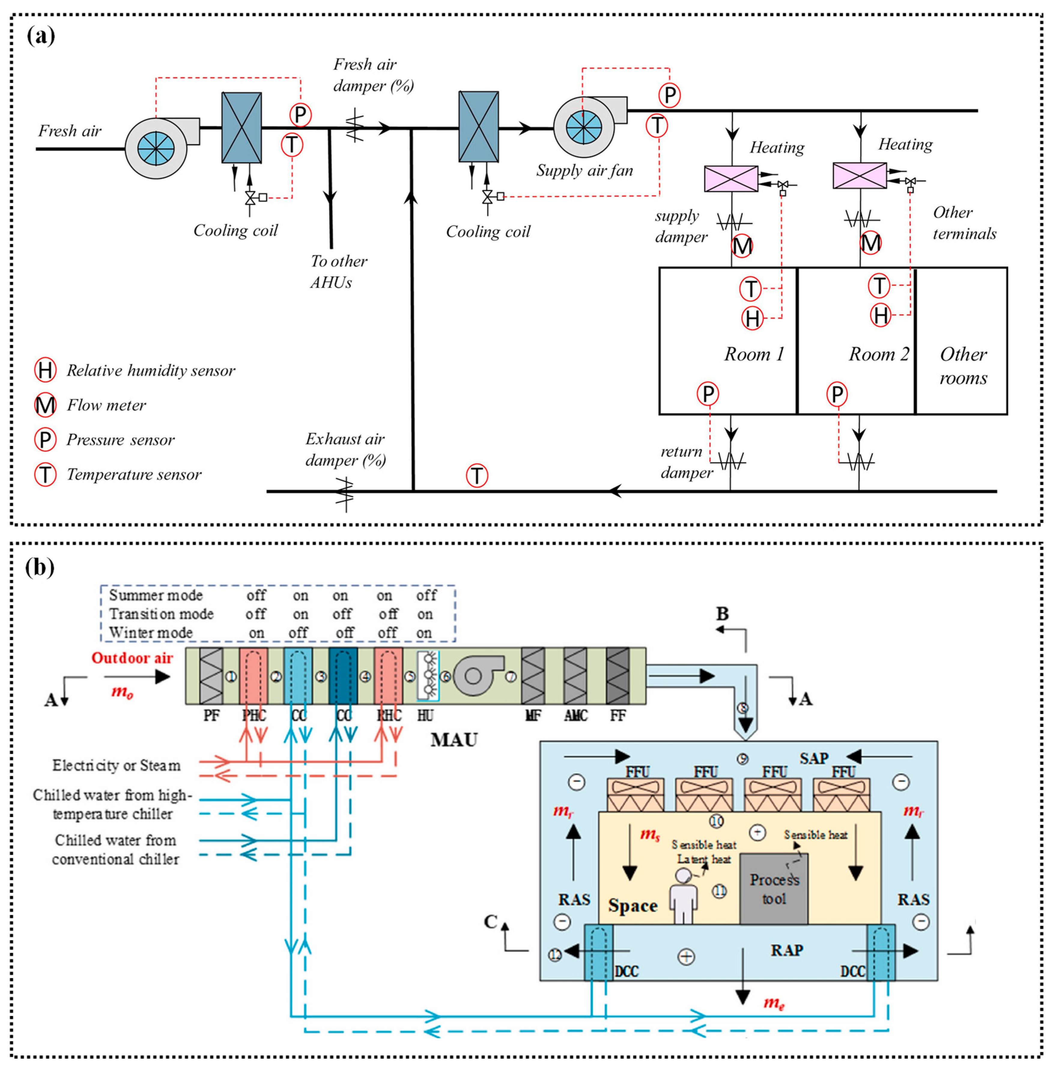
2.1. System Structures
2.2. Cleanroom Standards

| Standard | Limitations | Country | |||||||
|---|---|---|---|---|---|---|---|---|---|
| d = 0.5 μm (Unit: pcs/m3) | China | USA | Japan | Britain | German | Australian | ISO | ||
| GBJ 73-1984 [30] | GB 50073-2013 [27] | FS 209E: 1992 [31] | JIS B 9920: 2019 [28] | BS 5295: 1989 [32] | VDI 2083: 2003 [33] | AS 1386: 1989 [34] | ISO 14644-1: 2015 [26] | ||
| Class | - | 1 | 1 | ISO 1 | |||||
| 4(0) | 2 | 2 | 0 | ISO 2 | |||||
| 10 | M1 | ||||||||
| 35 | 3 | M1.5 | 3 | C | 1 | 0.035 | ISO 3 | ||
| 100 | M2 | ||||||||
| 352 | 4 | M2.5 | 4 | D | 2 | 0.35 | ISO 4 | ||
| 1000 | M3 | ||||||||
| 3520 | 100 | 5 | M3.5 | 5 | E, F | 3 | 3.5 | ISO 5 | |
| 10,000 | M4 | ||||||||
| 35,200 | 1000 | 6 | M4.5 | 6 | G, H | 4 | 35 | ISO 6 | |
| 100,000 | M5 | ||||||||
| 352,000 | 10,000 | 7 | M5.5 | 7 | R | 5 | 350 | ISO 7 | |
| 1,000,000 | M6 | ||||||||
| 3,520,000 | 100,000 | 8 | M6.5 | 8 | K | 6 | 3500 | ISO 8 | |
| 10,000,000 | M7 | ||||||||
| 35,200,000 | 9 | 9 | L | 7 | ISO 9 | ||||
2.3. System Characteristics
3. Optimization Strategies Based on System Air Delivery
3.1. Air Supply Parameter Optimization
3.1.1. Design Value Reduction
3.1.2. Actual Demand Consideration
3.1.3. Air Distribution Improvement
3.1.4. Comparison of the Advantages and Limitations
3.2. Fan Design Parameter Optimization
4. Optimization Strategies Based on Air Handling Process
4.1. Demand Reduction
4.2. Heat Recovery Adoption
4.3. Temperature–Humidity Decoupled Strategies
| Method | Type 1 | Class 2 | Power Consumption Reduction | Ref. |
|---|---|---|---|---|
| PD | B | ISO Class 7/8 | 69.6% of cooling (48.4 kW) and 87.8% of heating (50.9 kW) | [88] |
| PD | A | ISO Class 4/5 | 39.2–79.6% (Different climatic conditions) | [8] |
| FD | B | - | 15.04% (Annual energy consumptions compared to PD) | [89] |
| ADV | B | - | 21.64% (Annual energy consumptions compared to PD) | [89] |
| Adiabatic humidification | A | ISO Class 5/6 | Saved 6311 kW | [91] |
| Adiabatic humidification | A | - | 8% and 23% (Two cases) | [90] |
4.4. Comparison of the Advantages and Limitations
5. Optimization Strategies Based on Air Filters
5.1. Material Optimization
| Type | Specific Materials | Air Flow Rate | Resistance | Filtration Efficiency | Particle Size (μm) | Ref. |
|---|---|---|---|---|---|---|
| Synthetic polymer fibers | Nylon 6 nanofibers | 5 cm/s | 150 Pa | 99.993% | 0.3 | [106] |
| PTFE + Poly (vinyl pyrrolidone) (PVP) | - | 89.9 Pa | 99.72% | - | [100] | |
| Polyvinyl Chloride (PVC) + Polyurethane (PU) | 5.3 cm/s | 144 Pa | 99.5% | 0.3–0.5 | [107] | |
| Polyacrylonitrile (PAN) + Polycaprolactone (PCL) | 0.3 m/s | 121 Pa | 99.95% | PM2.5 | [108] | |
| PAN + Poly (acrylic acid) (PAA) | 5.3 cm/s | 160 Pa | 99.994% | 0.3–0.5 | [101] | |
| PAN + Poly (ethylene oxide) (PEO) + Polysulfone (PSU) | 32 L/min | 95 Pa | 99.992% | 0.3–0.5 | [109] | |
| PAN + PA-6 | 5.3 cm/s | 117.5 Pa | 99.9998% | 0.3 | [102] | |
| PSU + PAN + PA-6 | - | 118 Pa | 99.992% | 0.3 | [110] | |
| PVDF + FPU | - | 67 Pa | 99.98% | 0.3 | [111] | |
| PVDF + HFP | 5.3 cm/s | 71.4 Pa | 99.50% | PM0.3 | [112] | |
| PSU + TiO2 nanoparticles | 30 L/min | 45.3 Pa | 99.997% | 0.3–0.5 | [113] | |
| PVDF + Negative Ions Powder (NIP) | - | 40.5 Pa | 99.99% | PM2.5 | [114] | |
| PVDF + SiO2 + Ag | 0.049 m/s | 101.2 Pa | 99.94% | 0.3 | [115] | |
| PAN + Ag | 0.05 m/s | 68.13 Pa | >98% | 0.3 | [103] | |
| PAN + TiO2 | 0.05 m/s | 183.47 Pa | ~100% | 0.3 | [103] | |
| PAN + TiO2 | 4 cm/s | - | 99% | 0.3 | [104] | |
| Polylactic Acid (PLA) + TiO2 | - | 128.7 Pa | 99.996% | - | [105] | |
| Natural polymer fibers | Zein | 8 L/min | 15.18 Pa | 97.36% | PM2.5 | [116] |
| Gelatin | 0.06 m/s | 148 Pa | 97–99% | 0.3–5 | [117] | |
| Sericin | 145 m3/h | - | ~100% | PM2.5 | [118] | |
| Porous materials | Metal foams | 0.1 m/s | ~58 Pa | 96.6% | 0.1–0.4 | [119] |
| Metal foams | 0.5 m/s | 10.8 Pa | 78.9% | 0.3 | [120] | |
| Carbon foam | - | 112 Pa | >99% | PM2.5 | [121] |
5.2. Structural Optimization
| Specific Materials | Type | Air Flow Rate | Resistance | Filtration Efficiency | Particle Size (μm) | Ref. |
|---|---|---|---|---|---|---|
| PLA nanofibers | Porous structure | 32 L/min | 90.35 Pa | 99.9989% | PM0.3 | [131] |
| PLA fiber composite | Porous structure | 5.3 cm/s | 93.3 Pa | 99.999% | 0.26 | [132] |
| BaTiO3/PES | Protrusion structure | - | 67 Pa | 99.99% | - | [122] |
| SiO2 nanofilament-based Poly (m-phenylene isophthalamide) (PMIA) | Protrusion structure | - | 170 Pa | 97.33% | PM2.5 | [123] |
| Chitosan/ PEO@MOF- | Protrusion structure | 3.4 m3/h | 44 Pa | 99.95% | PM2.5 | [133] |
| PLA | Bead-on-string structure | 5.8 cm/s | 165.3 Pa | 99.997% | 0.26 | [126] |
| Graphene oxide-in-PAN composite | Bead-on-string structure | 5.31 cm/s | 8 Pa | 99.97% | PM2.5 | [127] |
| PVDF/SiO2 hollow fibers | Hollow structure | - | 100 Pa | 99.9999% | 0.01–0.42 | [134] |
| PVDF-PEG hollow fibers | Hollow structure | 9.2 cm/s | - | 99.999% | 0.03 | [135] |
| PVDF/TLNMs | Branched structure | 32 L/min | 124.2 Pa | 99.999% | 0.26 | [105] |
| PS/BTA | Branched structure | - | 22 Pa | 99.8% | 0.3–10 | [124] |
| Polyamide-66 (PA-66)/BaCl2/ Polypropylene (PP) | Net structure | 60 ± 2 L/min | ~245 Pa | 99.9% | - | [136] |
| PMIA | Net structure | 32 L/min | 92 Pa | 99.999% | 0.3–0.5 | [137] |
| PVDF | Net structure | 32 L/min | 66.7 Pa | 99.985% | - | [138] |
| PSU/PAN/PA-6 | Net structure | 32 L/min | 118 Pa | 99.992% | PM0.3 | [110] |
| N-6 PAN NNF | Net structure | 90 L/min | ~75 Pa | 99.99% | PM0.3 | [139] |

5.3. Electrostatic Force Combination
5.3.1. Electret Filters
5.3.2. Electrostatic Precipitators
| ESP Type | Air Flow Rate/Exchange Rate | Filtration Efficiency | Particle Size | Ref. |
|---|---|---|---|---|
| Flat plate (FP) ESP | 0.5 m/s | >96% | PM2.5 | [170] |
| FP ESP | 0.7 m/s | 76.7% | PM0.2 | [171] |
| FP ESP | 944 L/s | 70% | PM0.19–0.52 | [172] |
| FP ESP | 1.62 h−1 | 88% | PM0.3–0.4 | [159] |
| FP ESP | 1.62 h−1 | 99% | PM1–2 | [159] |
| Bipolar ESP | 0.8 m/s | 99.1% | PM0.3–90 | [173] |
| Non-metallic collection plates ESP | 2 m/s | 95% | PM0.1–0.3 | [160] |
| Polymer-arrayed ESP | 1 m/s | 90% | PM0.3 | [174] |
| ESP with dielectric coatings | 1.6 m/s | 92% | PM0.3–0.5 | [161] |
| ESP with dielectric coatings | 1.04 m/s | 95% | PM0.3 | [175] |
| Crenelated plate ESP | - | 88% | PM0.05 | [162] |
| Wavy Plate (WP) ESP | 1 m/s | 96% | PM0.5–2.5 | [176] |
| WP ESP | 1 m/s | ~96% (24% higher than FP) | PM1 | [177] |
| Cylindrical ESP | 200 m3/h | 94.6% | PM0.3 | [178] |
| IFD | 6 m3/min | 90.7% (48.5% higher than ESP) | PM0.5–1 | [179] |
| IFD | 1 m/s | 99.8% | PM2.5 | [166] |
| IFD | 2.5 m/s | 78.6% (12.4–38% higher than ESP) | PM0.3–0.5 | [168] |
| IFD | 1.13 m/s | 98% | PM2.5 | [169] |
6. Optimization Strategies Based on Intelligent Algorithms
7. Discussion and Future Perspectives
7.1. Discussion
7.2. Future Perspectives
7.2.1. Optimization of Non-Consumable Filtration Technology and Its System Construction
7.2.2. The Intelligent Evolution of Control Strategies
7.2.3. The Introduction of Renewable Energy
7.2.4. Integration and Collaborative Optimization of Multiple Energy-Saving Strategies
8. Conclusions
Author Contributions
Funding
Data Availability Statement
Acknowledgments
Conflicts of Interest
References
- Lian, J.Z.; Siebler, F.; Steubing, B.R.P.; Jesorka, A.; Barbarossa, V.; Wang, R.; Leo, K.; Sen, I.; Cucurachi, S. Quantifying the present and future environmental sustainability of cleanrooms. Cell Rep. Sustain. 2024, 1, 100219. [Google Scholar]
- Zhao, W.; Li, H.; Wang, S. Energy performance and energy conservation technologies for high-tech cleanrooms: State of the art and future perspectives. Renew. Sust. Energ. Rev. 2023, 183, 113532. [Google Scholar] [CrossRef]
- Ohring, M. Chapter 3—Defects, Contaminants and Yield. In Reliability and Failure of Electronic Materials and Devices; Ohring, M., Ed.; Academic Press: San Diego, CA, USA, 1998; pp. 105–173. [Google Scholar]
- U.S. and Europe Cleanrooms Market Size, Share & Trends Analysis Report By End-Use (Hospitals, Compounding Pharmacies). 2022. Available online: https://www.grandviewresearch.com/industry-analysis/us-europe-cleanrooms-market (accessed on 23 March 2025).
- Mills, E.; Shamshoian, G.; Blazek, M.; Naughton, P.; Seese, R.S.; Tschudi, W.; Sartor, D. The business case for energy management in high-tech industries. Energy Effic. 2008, 1, 5–20. [Google Scholar] [CrossRef]
- Kong, D.; Hong, Y.; Yang, Y.; Gu, T.; Fu, Y.; Ye, Y.; Xi, W.; Zhang, Z. A parametric, control-integrated and machine learning-enhanced modeling method of demand-side HVAC systems in industrial buildings: A practical validation study. Appl. Energy 2025, 379, 124971. [Google Scholar] [CrossRef]
- Kircher, K.; Shi, X.; Patil, S.; Zhang, K.M. Cleanroom energy efficiency strategies: Modeling and simulation. Energy Build. 2010, 42, 282–289. [Google Scholar] [CrossRef]
- Zhao, W.; Li, H.; Wang, S. A comparative analysis on alternative air-conditioning systems for high-tech cleanrooms and their performance in different climate zones. Energy 2022, 261, 125284. [Google Scholar] [CrossRef]
- Chen, Z.; Hu, Y.; Ma, Z.; Yang, H.; Shang, L.; Skibniewski, M.J. Selecting optimal honeycomb structural materials for electronics clean rooms using a Bayesian best-worst method and ELECTRE III. J. Build. Eng. 2024, 85, 108703. [Google Scholar] [CrossRef]
- Den, W.; Bai, H.; Kang, Y. Organic Airborne Molecular Contamination in Semiconductor Fabrication Clean Rooms: A Review. J. Electrochem. Soc. 2006, 153, G149. [Google Scholar] [CrossRef]
- Lu, Y.; Cao, G.; Feng, X.; Wu, Y. Review on the adsorption of airborne molecular contaminants in electronic industry cleanrooms. Int. J. Low-Carbon Technol. 2022, 17, 1095–1103. [Google Scholar] [CrossRef]
- Matsuki, M.; Tanaka, N. Energy Saving System for Air Conditioning of Clean Room for Semiconductor Factory (Estimation of FMU System). Eng. Environ. Sci. 1998, 63, 49–52. [Google Scholar]
- Tschudi, W.; Mills, E.; Xu, T.; Rumsey, P. Measuring and Managing Cleanroom Energy Use. HPAC Eng. 2005, 77, 917796. [Google Scholar]
- Ma, Z.; Guan, B.; Liu, X.; Zhang, T. Performance analysis and improvement of air filtration and ventilation process in semiconductor clean air-conditioning system. Energy Build. 2020, 228, 110489. [Google Scholar] [CrossRef]
- Hu, S.C.; Lin, T.; Huang, S.H.; Fu, B.R.; Hu, M.H. Energy savings approaches for high-tech manufacturing factories. Case Stud. Therm. Eng. 2020, 17, 100569. [Google Scholar] [CrossRef]
- Chang, C.K.; Lin, T.; Hu, S.C.; Fu, B.R.; Hsu, J.S. Various Energy-Saving Approaches to a TFT-LCD Panel Fab. Sustainability 2016, 8, 907. [Google Scholar] [CrossRef]
- Ma, Z.; Liu, X.; Zhang, T. Measurement and optimization on the energy consumption of fans in semiconductor cleanrooms. Build. Environ. 2021, 197, 107842. [Google Scholar] [CrossRef]
- Yu, K.T.; Su, C.L.; Kuo, J.L. Variable Recycled Air Controls of HVAC Systems for Energy Savings in High-Tech Industries. In Proceedings of the 2016 IEEE International Conference on Industrial Technology (ICIT), Taipei, Taiwan, 14–17 March 2016; pp. 215–220. [Google Scholar]
- Lin, T.; Zargar, O.A.; Wang, Z.; Hu, S.C.; Shih, Y.C.; Leggett, G. Energy saving for an air conditioning system applied in a thin-film-transistor liquid-crystal display (TFT LCD) high-tech fabrication plant (Fab). Int. J. Thermofluids 2022, 16, 100210. [Google Scholar] [CrossRef]
- Zaatari, M.; Novoselac, A.; Siegel, J. The relationship between filter pressure drop, indoor air quality, and energy consumption in rooftop HVAC units. Build. Environ. 2014, 73, 151–161. [Google Scholar] [CrossRef]
- Wang, S.; Zhao, X.; Yin, X.; Yu, J.; Ding, B. Electret Polyvinylidene Fluoride Nanofibers Hybridized by Polytetrafluoroethylene Nanoparticles for High-Efficiency Air Filtration. ACS Appl. Mater. Interfaces 2016, 8, 23985–23994. [Google Scholar] [CrossRef]
- Li, X.; Wang, N.; Fan, G.; Yu, J.; Gao, J.; Sun, G.; Ding, B. Electreted polyetherimide–silica fibrous membranes for enhanced filtration of fine particles. J. Colloid Interface Sci. 2015, 439, 12–20. [Google Scholar] [CrossRef]
- Shi, J.; Yu, N.; Yao, W. Energy Efficient Building HVAC Control Algorithm with Real-time Occupancy Prediction. Energy Procedia 2017, 111, 267–276. [Google Scholar] [CrossRef]
- Azuatalam, D.; Lee, W.L.; de Nijs, F.; Liebman, A. Reinforcement learning for whole-building HVAC control and demand response. Energy AI 2020, 2, 100020. [Google Scholar] [CrossRef]
- Zhuang, C.; Shan, K.; Wang, S. Coordinated demand-controlled ventilation strategy for energy-efficient operation in multi-zone cleanroom air-conditioning systems. Build. Environ. 2021, 191, 107588. [Google Scholar] [CrossRef]
- International Organization for Standardization. Cleanrooms and Associated Controlled Environments—Part 1: Classification of Air Cleanliness by Particle Concentration; International Organization for Standardization: Geneva, Switzerland, 2015. [Google Scholar]
- Ministry of Housing and Urban-Rural Development of the People’s Republic of China. Code for Design of Clean Room; China Standard Press: Beijing, China, 2013.
- Japanese Standards Association. Cleanrooms and Associated Controlled Environments—Part 1: Classification of Air Cleanliness by Particle Concentration; Japanese Standards Association: Tokyo, Japan, 2019. [Google Scholar]
- Liu, J. Optimization of Purification Air-Conditioning System in Electronic Clean Workshop; Chongqing University: Chongqing, China, 2022. (In Chinese) [Google Scholar]
- Standardization Administration of the People’s Republic of China. Specifications for the Design of Clean Factory Buildings; China Standard Press: Beijing, China, 1984.
- Institute of Environmental Sciences. Federal Standard 209E: Airborne Particulate Cleanliness Classes in Cleanrooms and Clean Zones; United States General Services Administration: Washington, DC, USA, 1992.
- British Standards Institution. Environmental Cleanliness in Enclosed Spaces Part 1: Specification for Clean Rooms and Clean Air Devices; British Standards Institution: London, UK, 1989. [Google Scholar]
- Technische Gebäudeausrüstung. Cleanroom Technology—Particulate Air Cleanliness Classes; Verein Deutscher Ingenieure: Düsseldorf, Germany, 2003. [Google Scholar]
- Committee ME/60. Controlled Environments, Cleanrooms and Clean Workstations; Council of Standards Australia: Sydney, Australia, 1989. [Google Scholar]
- Ministry of Housing and Urban-Rural Development of the People’s Republic of China. Standard for Design of Pharmaceutical Industry Clean Room; China Standard Press: Beijing, China, 2019.
- Yin, J.; Liu, X.; Guan, B.; Ma, Z.; Zhang, T. Performance analysis and energy saving potential of air conditioning system in semiconductor cleanrooms. J. Build. Eng. 2021, 37, 102158. [Google Scholar] [CrossRef]
- Dixon, A.M. Environmental Monitoring for Cleanrooms and Controlled Environments, 1st ed.; CRC Press: Boca Raton, FL, USA, 2016; pp. 1–230. [Google Scholar]
- Faulkner, D.; DiBartolomeo, D.; Wang, D. Demand Controlled Filtration in an Industrial Cleanroom; Lawrence Berkeley National Laboratory: Berkeley, CA, USA, 2007.
- Tong, X. Layered Air Conditioning System Design of Large-space clean Facility. Contam. Control. Air-Cond. Technol. 2017, 36–38. (In Chinese) [Google Scholar]
- Loomans, M.G.L.C.; Molenaar, P.C.A.; Kort, H.S.M.; Joosten, P.H.J. Energy demand reduction in pharmaceutical cleanrooms through optimization of ventilation. Energy Build. 2019, 202, 109346. [Google Scholar] [CrossRef]
- National Medical Products Administration. Good Manufacturing Practice of Medical Products; China Standard Press: Beijing, China, 2010.
- Sun, W. Cleanroom Fan Energy Reduction—Airflow Control Retrofit Based on Continuous, Real-time Particle Sensing. J. IEST 2019, 62, 11–25. [Google Scholar] [CrossRef]
- Faulkner, D.; Fisk, W.; Walton, J. Energy Savings in Cleanrooms from Demand-Controlled Filtration. J. IES 1996, 39, 21–27. Available online: https://eta-publications.lbl.gov/sites/default/files/lbnl-38869.pdf (accessed on 20 March 2025). [CrossRef]
- Hu, S.C.; Shiue, A. Validation and application of the personnel factor for the garment used in cleanrooms. Build. Environ. 2016, 97, 88–95. [Google Scholar] [CrossRef]
- Strauss, L.; Larkin, J.; Zhang, K.M. The use of occupancy as a surrogate for particle concentrations in recirculating, zoned cleanrooms. Energy Build. 2011, 43, 3258–3262. [Google Scholar] [CrossRef]
- Loomans, M.G.L.C.; Ludlage, T.B.J.; van den Oever, H.; Molenaar, P.C.A.; Kort, H.S.M.; Joosten, P.H.J. Experimental investigation into cleanroom contamination build-up when applying reduced ventilation and pressure hierarchy conditions as part of demand controlled filtration. Build. Environ. 2020, 176, 106861. [Google Scholar] [CrossRef]
- Liu, J.; Zhang, L.; Yang, J.; Chen, Y.; Zhang, X. Study on pressure control and energy saving of cleanroom in purification air conditioning system. Energy Build. 2021, 253, 111502. [Google Scholar] [CrossRef]
- Tschudi, W.; Faulkner, D.; Hebert, A. Energy efficiency strategies for cleanrooms without compromising environmental conditions. ASHRAE Symp. 2005, 3, 637–645. [Google Scholar]
- Wang, Y.; Li, Y.; Zhou, L. Pressure Gradient Control and Energy-saving Operation Strategy Study on a Multi-zone Cleanroom. Procedia Eng. 2015, 121, 1998–2005. [Google Scholar] [CrossRef]
- Yang, J.; Zhang, L.; Liu, J.; Chen, Y. Adjustment strategy for supply air volume balance and algorithm for multi-room differential pressure gradient in an air conditioning purifier system. Build. Environ. 2023, 243, 110647. [Google Scholar] [CrossRef]
- Jing, G.; Cai, W.; Zhang, X.; Cui, C.; Yin, X.; Xian, H. An energy-saving oriented air balancing strategy for multi-zone demand-controlled ventilation system. Energy 2019, 172, 1053–1065. [Google Scholar] [CrossRef]
- Cheng, F.; Cui, C.; Cai, W.; Zhang, X.; Ge, Y.; Li, B. A novel data-driven air balancing method with energy-saving constraint strategy to minimize the energy consumption of ventilation system. Energy 2022, 239, 122146. [Google Scholar] [CrossRef]
- Fan, K.; Chen, Y.; Lai, C.; Cai, Q.; Wu, X. Energy-saving control of multi-zone purification ventilation system based on a novel multi-task learning framework. Energy 2025, 317, 134744. [Google Scholar] [CrossRef]
- Villafruela, J.M.; Castro, F.; San José, J.F.; Saint-Martin, J. Comparison of air change efficiency, contaminant removal effectiveness and infection risk as IAQ indices in isolation rooms. Energy Build. 2013, 57, 210–219. [Google Scholar] [CrossRef]
- Shi, J. Research on Energy-Saving of HVAC System in Semiconductor Plant; Xi’an University of Science and Technology: Xi’an, China, 2014. (In Chinese) [Google Scholar]
- Saidi, M.H.; Sajadi, B.; Molaeimanesh, G.R. The effect of source motion on contaminant distribution in the cleanrooms. Energy Build. 2011, 43, 966–970. [Google Scholar] [CrossRef]
- Lin, T.; Tung, Y.; Hu, S.; Lin, C. Effects of the Removal of 0.1 μm Particles in Industrial Cleanrooms with a Fan Dry Coil Unit (FDCU) Return System. Aerosol Air Qual. Res. 2010, 10, 571–580. [Google Scholar] [CrossRef]
- Du, J.S.; Lin, T.; Hu, S.C. Research of Energy Consumption by Outdoor Infiltration Quantity and Negative Pressure in Cleanroom Supply Air Plenum. In Proceedings of the ACRA 2016—8th Asian Conference on Refrigeration and Air-Conditioning, Taipei, Taiwan, 15–17 May 2016. [Google Scholar]
- Lin, T.; Hu, S.C.; Xu, T. Developing an innovative fan dry coil unit (FDCU) return system to improve energy efficiency of environmental control for mission critical cleanrooms. Energy Build. 2015, 90, 94–105. [Google Scholar] [CrossRef]
- Gholamian, M.; Rao, G.K.M.; Panitapu, B. Effect of axial gap between inlet nozzle and impeller on efficiency and flow pattern in centrifugal fans, numerical and experimental analysis. Case Stud. Therm. Eng. 2013, 1, 26–37. [Google Scholar] [CrossRef]
- Meng, F.; Xie, G.; Wang, L.; Dong, Q.; Yang, Z.; Zhao, F. Optimization of centrifugal fan blade profile based on Kriging model and GA-PSO simultaneous algorithm. J. Mach. Des. 2018, 35, 84–91. (In Chinese) [Google Scholar]
- Zhou, S.; Zhou, H.; Yang, K.; Dong, H.; Gao, Z. Research on blade design method of multi-blade centrifugal fan for building efficient ventilation based on Hicks-Henne function. Sustain. Energy Technol. Assess. 2021, 43, 100971. [Google Scholar] [CrossRef]
- Varun Ch, S.; Anantharaman, K.; Rajasekaran, G. Effect of blade number on the performance of centrifugal fan. Mater. Today Proc. 2023, 72, 1143–1152. [Google Scholar] [CrossRef]
- Yu, Z.; Li, S.; He, W.; Wang, W.; Huang, D.; Zhu, Z. Numerical Simulation of Flow Field for a Whole Centrifugal Fan and Analysis of the Effects of Blade Inlet Angle and Impeller Gap. HVAC&R Res. 2005, 11, 263–283. [Google Scholar]
- Meng, F.; Dong, Q.; Wang, Y.; Wang, P.; Zhang, C. Numerical Optimization of Impeller for Backward-Curved Centrifugal Fan by Response Surface Methodology (RSM). Res. J. Appl. Sci. Eng. Technol. 2013, 6, 2436–2442. [Google Scholar] [CrossRef]
- Zhou, S.; Yang, K.; Zhang, W.; Zhang, K.; Wang, C.; Jin, W. Optimization of Multi-Blade Centrifugal Fan Blade Design for Ventilation and Air-Conditioning System Based on Disturbance CST Function. Appl. Sci. 2021, 11, 7784. [Google Scholar] [CrossRef]
- Ding, H.; Chang, T.; Lin, F. The Influence of the Blade Outlet Angle on the Flow Field and Pressure Pulsation in a Centrifugal Fan. Processes 2020, 8, 1422. [Google Scholar] [CrossRef]
- Meng, F.; Wang, L.; Ming, W.; Zhang, H. Aerodynamics Optimization of Multi-Blade Centrifugal Fan Based on Extreme Learning Machine Surrogate Model and Particle Swarm Optimization Algorithm. Metals 2023, 13, 1222. [Google Scholar] [CrossRef]
- Zhang, L.; Wang, S.; Hu, C.; Zhang, Q. Multi-objective optimization design and experimental investigation of centrifugal fan performance. Chin. J. Mech. Eng. 2013, 26, 1267–1276. [Google Scholar] [CrossRef]
- Selvaraj, T.; Hariharasakthisudhan, P.; Pandiaraj, S.; Sathickbasha, K.; Noorani, A. Optimizing the Design Parameters of Radial Tip Centrifugal Blower for Dust Test Chamber Application Through Numerical and Statistical Analysis. FME Trans. 2020, 48, 236–245. [Google Scholar] [CrossRef]
- Zhou, S.; Dong, H.; Zhang, K.; Zhou, H.; Jin, W.; Wang, C. Optimal design of multi-blade centrifugal fan based on partial coherence analysis. Proc. Inst. Mech. Eng. Part C J. Mech. Eng. Sci. 2022, 236, 894–907. [Google Scholar] [CrossRef]
- Meng, F.; Zhang, Z.; Wang, L. Volute Optimization Based on Self-Adaption Kriging Surrogate Model. Int. J. Chem. Eng. 2022, 2022, 6799201. [Google Scholar] [CrossRef]
- Jiang, W.; Zhang, P.; Yang, Z.; Pei, Q. Aerodynamic Optimization of Centrifugal Fan for Volute by Response Sureface Methodology. Compress. Blower Fan Technol. 2019, 61, 23–28. (In Chinese) [Google Scholar]
- Benchikh Le Hocine, A.E.; Poncet, S.; Fellouah, H. CFD modeling and optimization by metamodels of a squirrel cage fan using OpenFoam and Dakota: Ventilation applications. Build. Environ. 2021, 205, 108145. [Google Scholar] [CrossRef]
- Wang, K.; Ju, Y.; Zhang, C. Design of Multi-blade Centrifugal Fan Based on Grouping Model and Bionic Volute Tongue. J. Eng. Thermophys. 2017, 38, 1671–1675. (In Chinese) [Google Scholar]
- Zhao, W.; Li, H.; Wang, S. A generic design optimization framework for semiconductor cleanroom air-conditioning systems integrating heat recovery and free cooling for enhanced energy performance. Energy 2024, 286, 129600. [Google Scholar] [CrossRef]
- Yin, J.; Zhang, T.; Ma, Z.; Liu, X. Feasibility analysis of canceling reheating after condensation dehumidification in semiconductor cleanrooms. J. Build. Eng. 2021, 43, 102589. [Google Scholar] [CrossRef]
- Yin, J.; Liu, X.; Guan, B.; Zhang, T. Performance and improvement of cleanroom environment control system related to cold-heat offset in clean semiconductor fabs. Energy Build. 2020, 224, 110294. [Google Scholar] [CrossRef]
- Hu, S.C.; Lin, T.; Fu, B.R.; Chang, C.K.; Cheng, I.Y. Analysis of energy efficiency improvement of high-tech fabrication plants. Int. J. Low-Carbon Technol. 2019, 14, 508–515. [Google Scholar] [CrossRef]
- Liao, P.Y.; Lin, T.; Zargar, O.A.; Hsu, C.J.; Chou, C.H.; Shih, Y.C.; Hu, S.C.; Leggett, G. Energy Consumption and Carbon Emission Reduction in HVAC System of a Dynamic Random Access Memory (DRAM) Semiconductor Fabrication Plant (fab). IEEE Trans. Semicond. Manuf. 2024, 37, 174–184. [Google Scholar] [CrossRef]
- Roulet, C.A.; Heidt, F.D.; Foradini, F.; Pibiri, M.C. Real heat recovery with air handling units. Energy Build. 2001, 33, 495–502. [Google Scholar] [CrossRef]
- Tsao, J.M.; Hu, S.C.; Xu, T.; Chan, D.Y.L. Capturing energy-saving opportunities in make-up air systems for cleanrooms of high-technology fabrication plant in subtropical climate. Energy Build. 2010, 42, 2005–2013. [Google Scholar] [CrossRef]
- Liu, C.; Ma, H.; Liu, S.; Zhang, H.; Ma, D. Heat recovery technology and energy-saving effect analysis apply to cleanroom exhaust waste heat characteristics. Energy Build. 2024, 306, 113935. [Google Scholar] [CrossRef]
- Tsao, J.J.M.; Hu, S.C.; Kao, W.C.; Chien, L.H. Clean Room Exhaust Energy Recovery Optimization Design. In Proceedings of the 2010 ASHRAE Winter Conference, Orlando, Florida, 23–27 January 2010; Volume 116, pp. 81–86. [Google Scholar]
- Kim, M.H.; Kim, J.; Kwon, O.; Choi, A.; Jeong, J.W. Energy conservation potential of an indirect and direct evaporative cooling assisted 100% outdoor air system. Build. Serv. Eng. Res. Technol. 2011, 32, 345–360. [Google Scholar] [CrossRef]
- Tsao, J.M.; Hu, S.C.; Chan, D.Y.L.; Hsu, R.T.C.; Lee, J.C.C. Saving energy in the make-up air unit (MAU) for semiconductor clean rooms in subtropical areas. Energy Build. 2008, 40, 1387–1393. [Google Scholar] [CrossRef]
- Luo, W.J.; Wu, Y.L.; Lin, C.M.; Cheng, S.F.; Chen, C.N. A case study on energy saving of the facility systems for 12-inch semiconductor wafer fabs in Taiwan. Int. J. Phys. Sci. 2011, 6, 3597–3607. [Google Scholar]
- Shan, K.; Wang, S. Energy efficient design and control of cleanroom environment control systems in subtropical regions—A comparative analysis and on-site validation. Appl. Energy 2017, 204, 582–595. [Google Scholar] [CrossRef]
- Zhuang, C.; Wang, S.; Shan, K. Adaptive full-range decoupled ventilation strategy and air-conditioning systems for cleanrooms and buildings requiring strict humidity control and their performance evaluation. Energy 2019, 168, 883–896. [Google Scholar] [CrossRef]
- Jo, M.S.; Shin, J.H.; Kim, W.J.; Jeong, J.W. Energy-Saving Benefits of Adiabatic Humidification in the Air Conditioning Systems of Semiconductor Cleanrooms. Energies 2017, 10, 1774. [Google Scholar] [CrossRef]
- Chen, J.; Hu, S.C.; Chien, L.H.; Tsao, J.; Lin, T. Humidification of Large-Scale Cleanrooms by Adiabatic Humidification Method in Subtropical Areas: An Industrial Case Study. ASHRAE Trans. 2009, 115, 299–305. [Google Scholar]
- Li, C.; Yang, B.; Zhao, A.; Wu, J.; Zeng, X.; Li, Z. Sterilization potential of Gas-Water Mixed Ion (GWMI) technology and its device for microorganisms in the built environment. J. Build. Eng. 2024, 94, 109756. [Google Scholar] [CrossRef]
- Li, C.; Wang, H.; Zeng, X.; Li, X.; Jin, R.; Chi, Y.; Liu, Q.; Bai, L.; Li, Z.; Tham, K.W. Strategies for enhancing performance sustainability of air filters: Challenges and future directions. Sep. Purif. Technol. 2025, 133912. [Google Scholar] [CrossRef]
- Sun, Z.; Liang, Y.; He, W.; Jiang, F.; Song, Q.; Tang, M.; Wang, J. Filtration performance and loading capacity of nano-structured composite filter media for applications with high soot concentrations. Sep. Purif. Technol. 2019, 221, 175–182. [Google Scholar] [CrossRef]
- Zhang, W.; Deng, S.; Zhang, S.; Yang, Z.; Lin, Z. Energy consumption performance optimization of PTFE HEPA filter media during dust loading through compositing them with the efficient filter medium. Sustain. Cities Soc. 2022, 78, 103657. [Google Scholar] [CrossRef]
- Zeng, X.; Li, C.; Li, Z.; Tao, Z.; Li, M. Review of research advances in microbial sterilization technologies and applications in the built environment. J. Environ. Sci. 2025, 154, 314–348. [Google Scholar] [CrossRef]
- Wang, J.; Tronville, P. Toward standardized test methods to determine the effectiveness of filtration media against airborne nanoparticles. J. Nanopart. Res. 2014, 16, 2417. [Google Scholar] [CrossRef]
- Wang, C.; Otani, Y. Removal of Nanoparticles from Gas Streams by Fibrous Filters: A Review. Ind. Eng. Chem. Res. 2013, 52, 5–17. [Google Scholar] [CrossRef]
- Lv, D.; Wang, R.; Tang, G.; Mou, Z.; Lei, J.; Han, J.; De Smedt, S.; Xiong, R.; Huang, C. Ecofriendly Electrospun Membranes Loaded with Visible-Light-Responding Nanoparticles for Multifunctional Usages: Highly Efficient Air Filtration, Dye Scavenging, and Bactericidal Activity. ACS Appl. Mater. Interfaces 2019, 11, 12880–12889. [Google Scholar] [CrossRef]
- Wang, A.; Li, X.; Hou, T.; Lu, Y.; Zhou, J.; Zhang, X.; Yang, B. High efficiency, low resistance and high temperature resistance PTFE porous fibrous membrane for air filtration. Mater. Lett. 2021, 295, 129831. [Google Scholar] [CrossRef]
- Liu, Y.; Park, M.; Ding, B.; Kim, J.; El-Newehy, M.; Al-Deyab, S.S.; Kim, H.-Y. Facile electrospun Polyacrylonitrile/poly(acrylic acid) nanofibrous membranes for high efficiency particulate air filtration. Fibers Polym. 2015, 16, 629–633. [Google Scholar] [CrossRef]
- Yang, Y.; Zhang, S.; Zhao, X.; Yu, J.; Ding, B. Sandwich structured polyamide-6/polyacrylonitrile nanonets/bead-on-string composite membrane for effective air filtration. Sep. Purif. Technol. 2015, 152, 14–22. [Google Scholar] [CrossRef]
- Canalli Bortolassi, A.C.; Guerra, V.G.; Aguiar, M.L.; Soussan, L.; Cornu, D.; Miele, P.; Bechelany, M. Composites Based on Nanoparticle and Pan Electrospun Nanofiber Membranes for Air Filtration and Bacterial Removal. Nanomaterials 2019, 9, 1740. [Google Scholar] [CrossRef]
- Cho, D.; Naydich, A.; Frey, M.W.; Joo, Y.L. Further improvement of air filtration efficiency of cellulose filters coated with nanofibers via inclusion of electrostatically active nanoparticles. Polymer 2013, 54, 2364–2372. [Google Scholar] [CrossRef]
- Li, Z.; Kang, W.; Zhao, H.; Hu, M.; Ju, J.; Deng, N.; Cheng, B. Fabrication of a polyvinylidene fluoride tree-like nanofiber web for ultra high performance air filtration. RSC Adv. 2016, 6, 91243–91249. [Google Scholar] [CrossRef]
- Ahn, Y.C.; Park, S.K.; Kim, G.T.; Hwang, Y.J.; Lee, C.G.; Shin, H.S.; Lee, J.K. Development of high efficiency nanofilters made of nanofibers. Curr. Appl. Phys. 2006, 6, 1030–1035. [Google Scholar] [CrossRef]
- Wang, N.; Raza, A.; Si, Y.; Yu, J.; Sun, G.; Ding, B. Tortuously structured polyvinyl chloride/polyurethane fibrous membranes for high-efficiency fine particulate filtration. J. Colloid Interface Sci. 2013, 398, 240–246. [Google Scholar] [CrossRef]
- Jo, G.; Kwon, J.; Kang, H.S. Engineering electrospun PAN/PCL blend for high-performance and eco-friendly particulate matter filtration. React. Funct. Polym. 2024, 204, 106026. [Google Scholar] [CrossRef]
- Zhang, S.; Liu, H.; Yin, X.; Yu, J.; Ding, B. Anti-deformed Polyacrylonitrile/Polysulfone Composite Membrane with Binary Structures for Effective Air Filtration. ACS Appl. Mater. Interfaces 2016, 8, 8086–8095. [Google Scholar] [CrossRef]
- Zhang, S.; Tang, N.; Cao, L.; Yin, X.; Yu, J.; Ding, B. Highly Integrated Polysulfone/Polyacrylonitrile/Polyamide-6 Air Filter for Multilevel Physical Sieving Airborne Particles. ACS Appl. Mater. Interfaces 2016, 8, 29062–29072. [Google Scholar] [CrossRef] [PubMed]
- Shao, W.; Zhu, S.; Zhu, L.; Han, W.; Xu, H.; Nie, G.; Liang, S.; Wang, R.; Liu, F. Stable manufacturing of electrospun PVDF/FPU multiscale nanofiber membranes and application of high efficiency protective mask filter elements. Sep. Purif. Technol. 2025, 359, 130511. [Google Scholar] [CrossRef]
- Wang, X.; Wang, Q.; Zhang, W.; Cao, R.; Chen, M.; Xiao, C. Polyvinylidene Fluoride-co-hexafluoropropyle Electrospun Nanofiber Membranes for PM0.3 Filtration. ACS Appl. Nano Mater. 2024, 7, 10216–10225. [Google Scholar] [CrossRef]
- Wan, H.; Wang, N.; Yang, J.; Si, Y.; Chen, K.; Ding, B.; Sun, G.; El-Newehy, M.; Al-Deyab, S.S.; Yu, J. Hierarchically structured polysulfone/titania fibrous membranes with enhanced air filtration performance. J. Colloid Interface Sci. 2014, 417, 18–26. [Google Scholar] [CrossRef]
- Zhao, X.; Li, Y.; Hua, T.; Jiang, P.; Yin, X.; Yu, J.; Ding, B. Low-Resistance Dual-Purpose Air Filter Releasing Negative Ions and Effectively Capturing PM2.5. ACS Appl. Mater. Interfaces 2017, 9, 12054–12063. [Google Scholar] [CrossRef]
- Wu, Y.; Li, X.; Zhong, Q.; Wang, F.; Yang, B. Preparation and filtration performance of antibacterial PVDF/SiO2/Ag composite nanofiber membrane. J. Build. Eng. 2023, 74, 106864. [Google Scholar] [CrossRef]
- Lin, S.; Liu, W.; Ren, L.; Luo, M.; Zhong, W. Building a Tailored Frame-Channel Structure for High-Performance Protein Air Filters. ACS Appl. Bio Mater. 2024, 7, 6229–6238. [Google Scholar] [CrossRef] [PubMed]
- Kadam, V.; Truong, Y.B.; Schutz, J.; Kyratzis, I.L.; Padhye, R.; Wang, L. Gelatin/β–Cyclodextrin Bio–Nanofibers as respiratory filter media for filtration of aerosols and volatile organic compounds at low air resistance. J. Hazard. Mater. 2021, 403, 123841. [Google Scholar] [CrossRef]
- Verma, V.K.; Subbiah, S.; Kota, S.H. Sericin-coated polyester based air-filter for removal of particulate matter and volatile organic compounds (BTEX) from indoor air. Chemosphere 2019, 237, 124462. [Google Scholar] [CrossRef]
- Malloy, J.; Quintana, A.; Jensen, C.J.; Liu, K. Efficient and Robust Metallic Nanowire Foams for Deep Submicrometer Particulate Filtration. Nano Lett. 2021, 21, 2968–2974. [Google Scholar] [CrossRef]
- Tian, E.; Mo, J.; Li, X. Electrostatically assisted metal foam coarse filter with small pressure drop for efficient removal of fine particles: Effect of filter medium. Build. Environ. 2018, 144, 419–426. [Google Scholar] [CrossRef]
- Li, Z.; Xu, J.; Sun, D.; Lin, T.; Huang, F. Nanoporous Carbon Foam for Water and Air Purification. ACS Appl. Nano Mater. 2020, 3, 1564–1570. [Google Scholar] [CrossRef]
- Wang, N.; Cai, M.; Yang, X.; Yang, Y. Electret nanofibrous membrane with enhanced filtration performance and wearing comfortability for face mask. J. Colloid Interface Sci. 2018, 530, 695–703. [Google Scholar] [CrossRef]
- Zhong, L.; Wang, T.; Liu, L.; Du, W.; Wang, S. Ultra-fine SiO2 nanofilament-based PMIA: A double network membrane for efficient filtration of PM particles. Sep. Purif. Technol. 2018, 202, 357–364. [Google Scholar] [CrossRef]
- Tian, H.; Fu, X.; Zheng, M.; Wang, Y.; Li, Y.; Xiang, A.; Zhong, W.H. Natural polypeptides treat pollution complex: Moisture-resistant multi-functional protein nanofabrics for sustainable air filtration. Nano Res. 2018, 11, 4265–4277. [Google Scholar] [CrossRef]
- Zhang, K.; Li, Z.; Kang, W.; Deng, N.; Yan, J.; Ju, J.; Liu, Y.; Cheng, B. Preparation and characterization of tree-like cellulose nanofiber membranes via the electrospinning method. Carbohydr. Polym. 2018, 183, 62–69. [Google Scholar] [CrossRef]
- Wang, Z.; Zhao, C.; Pan, Z. Porous bead-on-string poly(lactic acid) fibrous membranes for air filtration. J. Colloid Interface Sci. 2015, 441, 121–129. [Google Scholar] [CrossRef]
- Li, J.; Zhang, D.; Yang, T.; Yang, S.; Yang, X.; Zhu, H. Nanofibrous membrane of graphene oxide-in-polyacrylonitrile composite with low filtration resistance for the effective capture of PM2.5. J. Membr. Sci. 2018, 551, 85–92. [Google Scholar] [CrossRef]
- Zhu, Q.; Tang, X.; Feng, S.; Zhong, Z.; Yao, J.; Yao, Z. ZIF-8@SiO2 composite nanofiber membrane with bioinspired spider web-like structure for efficient air pollution control. J. Membr. Sci. 2019, 581, 252–261. [Google Scholar] [CrossRef]
- Yu, Z.; Fan, T.; Liu, Y.; Li, L.; Liu, J.; Yang, B.; Ramakrishna, S.; Long, Y.-Z. Efficient air filtration through advanced electrospinning techniques in nanofibrous Materials: A review. Sep. Purif. Technol. 2024, 349, 127773. [Google Scholar] [CrossRef]
- Su, J.; Yang, G.; Cheng, C.; Huang, C.; Xu, H.; Ke, Q. Hierarchically structured TiO2/PAN nanofibrous membranes for high-efficiency air filtration and toluene degradation. J. Colloid Interface Sci. 2017, 507, 386–396. [Google Scholar] [CrossRef] [PubMed]
- Xing, J.; Zhang, W.; Sun, S.; Liu, Z. Preparation of porous polylactic acid nanofibers and application in non-electret high-efficiency filtration composites. RSC Adv. 2024, 14, 14857–14867. [Google Scholar] [CrossRef] [PubMed]
- Wang, Z.; Pan, Z. Preparation of hierarchical structured nano-sized/porous poly(lactic acid) composite fibrous membranes for air filtration. Appl. Surf. Sci. 2015, 356, 1168–1179. [Google Scholar] [CrossRef]
- Pan, W.; Wang, J.; Sun, X.; Wang, X.; Jiang, J.; Zhang, Z.; Li, P.; Qu, C.; Long, Y.; Yu, G. Ultra uniform metal−organic framework-5 loading along electrospun chitosan/polyethylene oxide membrane fibers for efficient PM2.5 removal. J. Clean. Prod. 2020, 291, 125270. [Google Scholar] [CrossRef]
- Wang, L.Y.; Yu, L.E.; Lai, J.Y.; Chung, T.S. Developing ultra-high gas permeance PVDF hollow fibers for air filtration applications. Sep. Purif. Technol. 2018, 205, 184–195. [Google Scholar] [CrossRef]
- Wang, L.Y.; Yong, W.F.; Yu, L.E.; Chung, T.S. Design of high efficiency PVDF-PEG hollow fibers for air filtration of ultrafine particles. J. Membr. Sci. 2017, 535, 342–349. [Google Scholar] [CrossRef]
- Wang, N.; Wang, X.; Ding, B.; Yu, J.; Sun, G. Tunable fabrication of three-dimensional polyamide-66 nano-fiber/nets for high efficiency fine particulate filtration. J. Mater. Chem. 2012, 22, 1445–1452. [Google Scholar] [CrossRef]
- Zhang, S.; Liu, H.; Yin, X.; Li, Z.; Yu, J.; Ding, B. Tailoring Mechanically Robust Poly(m-phenylene isophthalamide) Nanofiber/nets for Ultrathin High-Efficiency Air Filter. Sci. Rep. 2017, 7, 40550. [Google Scholar] [CrossRef]
- Li, X.; Wang, C.; Huang, X.; Zhang, T.; Wang, X.; Min, M.; Wang, L.; Huang, H.; Hsiao, B.S. Anionic Surfactant-Triggered Steiner Geometrical Poly(vinylidene fluoride) Nanofiber/Nanonet Air Filter for Efficient Particulate Matter Removal. ACS Appl. Mater. Interfaces 2018, 10, 42891–42904. [Google Scholar] [CrossRef]
- Wang, N.; Yang, Y.; Al-Deyab, S.S.; El-Newehy, M.; Yu, J.; Ding, B. Ultra-light 3D nanofibre-nets binary structured nylon 6–polyacrylonitrile membranes for efficient filtration of fine particulate matter. J. Mater. Chem. 2015, 3, 23946–23954. [Google Scholar] [CrossRef]
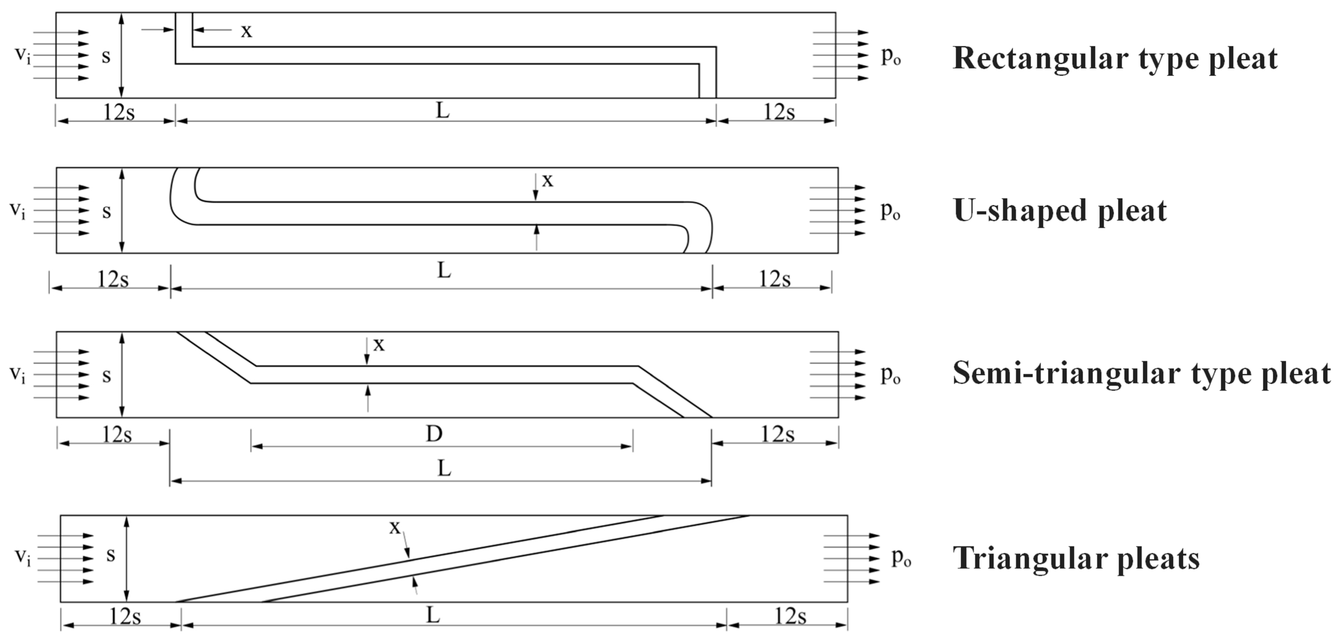
- Shukla, A.K.; Kumar, A.; Kumar, R.; Ranjan, P. Investigation of pleated air filters: Effects of various shapes and design parameters on flow patterns and pressure drop. Int. J. Interact. Des. Manuf. 2023, 18, 5057–5075. [Google Scholar] [CrossRef]
- Xue, J.; Xie, J.; Liu, W.; Xia, Y. Electrospun Nanofibers: New Concepts, Materials, and Applications. Acc. Chem. Res. 2017, 50, 1976–1987. [Google Scholar] [CrossRef]
- Zhang, S.; Liu, H.; Tang, N.; Zhou, S.; Yu, J.; Ding, B. Spider-Web-Inspired PM0.3 Filters Based on Self-Sustained Electrostatic Nanostructured Networks. Adv. Mater. 2020, 32, 2002361. [Google Scholar] [CrossRef] [PubMed]
- Tian, E.; Mo, J.; Long, Z.; Luo, H.; Zhang, Y. Experimental study of a compact electrostatically assisted air coarse filter for efficient particle removal: Synergistic particle charging and filter polarizing. Build. Environ. 2018, 135, 153–161. [Google Scholar] [CrossRef]
- Xiao, J.; Liang, J.; Zhang, C.; Tao, Y.; Ling, G.W.; Yang, Q.H. Advanced Materials for Capturing Particulate Matter: Progress and Perspectives. Small Methods 2018, 2, 1800012. [Google Scholar] [CrossRef]
- Liu, C.; Dai, Z.; He, B.; Ke, Q. The Effect of Temperature and Humidity on the Filtration Performance of Electret Melt-Blown Nonwovens. Materials 2020, 13, 4774. [Google Scholar] [CrossRef] [PubMed]
- Sun, Q.; Leung, W.W.F. Charged PVDF multi-layer filters with enhanced filtration performance for filtering nano-aerosols. Sep. Purif. Technol. 2019, 212, 854–876. [Google Scholar] [CrossRef]
- Leung, W.W.F.; Sun, Q. Electrostatic charged nanofiber filter for filtering airborne novel coronavirus (COVID-19) and nano-aerosols. Sep. Purif. Technol. 2020, 250, 116886. [Google Scholar] [CrossRef]
- Cai, R.-R.; Li, S.-Z.; Zhang, L.-Z.; Lei, Y. Fabrication and performance of a stable micro/nano composite electret filter for effective PM2.5 capture. Sci. Total Environ. 2020, 725, 138297. [Google Scholar] [CrossRef]
- Liu, H.; Zhang, S.; Liu, L.; Yu, J.; Ding, B. High-Performance PM0.3 Air Filters Using Self-Polarized Electret Nanofiber/Nets. Adv. Funct. Mater. 2020, 30, 1909554. [Google Scholar] [CrossRef]
- Bai, Y.; Han, C.B.; He, C.; Gu, G.Q.; Nie, J.H.; Shao, J.J.; Xiao, T.X.; Deng, C.R.; Wang, Z.L. Washable Multilayer Triboelectric Air Filter for Efficient Particulate Matter PM2.5 Removal. Adv. Funct. Mater. 2018, 28, 1706680. [Google Scholar] [CrossRef]
- Han, K.S.; Lee, S.; Kim, M.; Park, P.; Lee, M.H.; Nah, J. Electrically Activated Ultrathin PVDF-TrFE Air Filter for High-Efficiency PM1.0 Filtration. Adv. Funct. Mater. 2019, 29, 1903633. [Google Scholar] [CrossRef]
- Hu, Q.; Zhang, W.; Ma, W.; Wang, X. Research progress of electrospinning nanofiber electret air filtration material. Cotton Text. Technol. 2023, 51, 79–84. (In Chinese) [Google Scholar]
- Zhang, X.; Wang, Y.; Liu, W.; Jin, X. Needle-punched electret air filters (NEAFs) with high filtration efficiency, low filtration resistance, and superior dust holding capacity. Sep. Purif. Technol. 2022, 282, 120146. [Google Scholar] [CrossRef]
- Kilic, A.; Shim, E.; Pourdeyhimi, B. Electrostatic Capture Efficiency Enhancement of Polypropylene Electret Filters with Barium Titanate. Aerosol Sci. Technol. 2015, 49, 666–673. [Google Scholar] [CrossRef]
- Jiang, P.; Zhao, X.; Li, Y.; Liao, Y.; Hua, T.; Yin, X.; Yu, J.; Ding, B. Moisture and oily molecules stable nanofibrous electret membranes for effectively capturing PM2.5. Compos. Commun. 2017, 6, 34–40. [Google Scholar] [CrossRef]
- Liu, C.; Hsu, P.C.; Lee, H.W.; Ye, M.; Zheng, G.; Liu, N.; Li, W.; Cui, Y. Transparent air filter for high-efficiency PM2.5 capture. Nat. Commun. 2015, 6, 6205. [Google Scholar] [CrossRef]
- Mizuno, A. Electrostatic precipitation. IEEE Trans. Dielectr. Electr. Insul. 2000, 7, 615–624. [Google Scholar] [CrossRef]
- Zuraimi, M.S.; Vuotari, M.; Nilsson, G.; Magee, R.; Kemery, B.; Alliston, C. Impact of dust loading on long term portable air cleaner performance. Build. Environ. 2017, 112, 261–269. [Google Scholar] [CrossRef]
- Zuraimi, M.S.; Tham, K.W. Reducing particle exposures in a tropical office building using electrostatic precipitators. Build. Environ. 2009, 44, 2475–2485. [Google Scholar] [CrossRef]
- Kim, H.J.; Han, B.; Kim, Y.J.; Yoa, S.J. Characteristics of an electrostatic precipitator for submicron particles using non-metallic electrodes and collection plates. J. Aerosol Sci. 2010, 41, 987–997. [Google Scholar] [CrossRef]
- Mo, J.; Tian, E.; Pan, J. New electrostatic precipitator with dielectric coatings to efficiently and safely remove sub-micro particles in the building environment. Sustain. Cities Soc. 2020, 55, 102063. [Google Scholar] [CrossRef]
- Fayyad, M.B.; González, A.A.; Iváncsy, T. Numerical study of the influence of using crenelated collecting plates on the electrostatic precipitators. J. Electrostat. 2023, 123, 103811. [Google Scholar] [CrossRef]
- Li, J.; Duan, L.; Chen, J.; Li, D.; Bao, S.; Wang, Z.; Wang, J.; Liao, J. Research of the effect of different corrugated dust collection plates on particle removal in electrostatic precipitators. Chem. Eng. Res. Des. 2023, 197, 323–333. [Google Scholar] [CrossRef]
- Afshari, A.; Ekberg, L.; Forejt, L.; Mo, J.; Rahimi, S.; Siegel, J.; Chen, W.; Wargocki, P.; Zurami, S.; Zhang, J. Electrostatic Precipitators as an Indoor Air Cleaner—A Literature Review. Sustainability 2020, 12, 8774. [Google Scholar] [CrossRef]
- Fan, J.N.; Yang, Y.; Wang, Y.; Chen, H.; Qian, B. Intense field dielectric purification of oil droplets in machining buildings. J. Build. Eng. 2024, 84, 108543. [Google Scholar] [CrossRef]
- Xiong, W.; Lin, Z.; Zhang, W.; Chen, T.; Zhao, C. Experimental and simulation studies on dust loading performance of a novel electrostatic precipitator with dielectric barrier electrodes. Build. Environ. 2018, 144, 119–128. [Google Scholar] [CrossRef]
- Bai, C. Household air conditioning removal of PM2.5 by IFD device. J. Appl. Sci. Technol. 2014, 58–60. (In Chinese) [Google Scholar]
- Wang, P.; Liu, J.; Wang, C.; Zhang, Z.; Li, J. A holistic performance assessment of duct-type electrostatic precipitators. J. Clean. Prod. 2022, 357, 131997. [Google Scholar] [CrossRef]
- Ren, J.; Liu, J. Fine particulate matter control performance of a new kind of suspended fan filter unit for use in office buildings. Build. Environ. 2019, 149, 468–476. [Google Scholar] [CrossRef]
- Jaworek, A.; Marchewicz, A.; Sobczyk, A.T.; Krupa, A.; Czech, T. Two-stage electrostatic precipitator with dual-corona particle precharger for PM2.5 particles removal. J. Clean. Prod. 2017, 164, 1645–1664. [Google Scholar] [CrossRef]
- Zhuang, Y.; Kim, Y.j.; Lee, T.G.; Biswas, P. Experimental and theoretical studies of ultra-fine particle behavior in electrostatic precipitators. J. Electrostat. 2000, 48, 245–260. [Google Scholar] [CrossRef]
- Morawska, L.; Agranovski, V.; Ristovski, Z.; Jamriska, M. Effect of face velocity and the nature of aerosol on the collection of submicrometer particles by electrostatic precipitatorAbstract. Indoor Air 2002, 12, 129–137. [Google Scholar] [CrossRef] [PubMed]
- Chang, Y.; Jia, P.; Shi, L.; Xiang, X. Corona discharging and particle collection of bipolar transverse plate ESP. J. Electrost. 2018, 96, 104–110. [Google Scholar] [CrossRef]
- Yun, S.J.; Min, B.R.; Seo, Y. A novel polymer-arrayed electrostatic precipitator with electrical resistance material for the removal of fine particles. J. Aerosol Sci. 2013, 57, 88–95. [Google Scholar] [CrossRef]
- Kim, H.J.; Han, B.; Kim, Y.J.; Oda, T.; Won, H. Submicrometer particle removal indoors by a novel electrostatic precipitator with high clean air delivery rate, low ozone emissions, and carbon fiber ionizer. Indoor Air 2013, 23, 369–378. [Google Scholar] [CrossRef]
- Asipuela, A.; Fayyad, M.B.; Iváncsy, T. Study and Numerical Simulation of a Duct-Type ESP with Wavy Collecting Electrodes and Different Circular Corona Electrodes Radius. In Proceedings of the 2022 IEEE 4th International Conference on Dielectrics (ICD), Palermo, Italy, 3–7 July 2022; pp. 234–238. [Google Scholar]
- Zhu, Y.; Gao, M.; Chen, M.; Shi, J.; Shangguan, W. Numerical simulation of capture process of fine particles in electrostatic precipitators under consideration of electrohydrodynamics flow. Powder Technol. 2019, 354, 653–675. [Google Scholar] [CrossRef]
- Wang, C.; Jiang, J.; Wang, P.; Kong, L.; Liu, J. Exploring the potential of a novel electrostatic precipitator as an alternative to air filters in air purifiers. Build. Environ. 2025, 270, 112535. [Google Scholar] [CrossRef]
- Macintosh, D.L.; Myatt, T.A.; Ludwig, J.F.; Baker, B.J.; Suh, H.H.; Spengler, J.D. Whole house particle removal and clean air delivery rates for in-duct and portable ventilation systems. J. Air Waste Manag. Assoc. 2008, 58, 1474–1482. [Google Scholar] [CrossRef]
- Ni, H.P.; Liu, C.Y.; Li, Y.; Chong, W.O.; Chou, J.S. Enhancing HVAC energy efficiency modeling in semiconductor manufacturing facilities using tree-structured parzen estimator-optimized deep learning. Build. Environ. 2025, 271, 112589. [Google Scholar] [CrossRef]
- Nasruddin; Sholahudin; Satrio, P.; Mahlia, T.M.I.; Giannetti, N.; Saito, K. Optimization of HVAC system energy consumption in a building using artificial neural network and multi-objective genetic algorithm. Sustain. Energy Technol. Assess. 2019, 35, 48–57. [Google Scholar] [CrossRef]
- Agouzoul, A.; Simeu, E. Predictive Control Method for Comfort and Thermal Energy Enhancement in Buildings. In Proceedings of the 2024 International Conference on Control, Automation and Diagnosis (ICCAD), Paris, France, 15–17 May 2024; pp. 1–6. [Google Scholar]
- Mawson, V.J.; Hughes, B.R. Optimisation of HVAC control and manufacturing schedules for the reduction of peak energy demand in the manufacturing sector. Energy 2021, 227, 120436. [Google Scholar] [CrossRef]
- Liu, G.; Gao, J.; Han, Z.; Yuan, Y. Hybrid model-based predictive HVAC control through fast prediction of transient indoor temperature fields. Build. Environ. 2025, 267, 112253. [Google Scholar] [CrossRef]
- Gao, G.; Li, J.; Wen, Y. DeepComfort: Energy-Efficient Thermal Comfort Control in Buildings Via Reinforcement Learning. IEEE Internet Things J. 2020, 7, 8472–8484. [Google Scholar] [CrossRef]
- Li, W.; Zhao, Y.; Zhang, J.; Jiang, C.; Chen, S.; Lin, L.; Wang, Y. Indoor temperature preference setting control method for thermal comfort and energy saving based on reinforcement learning. J. Build. Eng. 2023, 73, 106805. [Google Scholar] [CrossRef]
- Yuan, X.; Pan, Y.; Yang, J.; Wang, W.; Huang, Z. Study on the application of reinforcement learning in the operation optimization of HVAC system. Build. Simul. 2021, 14, 75–87. [Google Scholar] [CrossRef]
- Valladares, W.; Galindo, M.; Gutiérrez, J.; Wu, W.C.; Liao, K.K.; Liao, J.C.; Lu, K.C.; Wang, C.C. Energy optimization associated with thermal comfort and indoor air control via a deep reinforcement learning algorithm. Build. Environ. 2019, 155, 105–117. [Google Scholar] [CrossRef]
- Gupta, A.; Badr, Y.; Negahban, A.; Qiu, R.G. Energy-efficient heating control for smart buildings with deep reinforcement learning. J. Build. Eng. 2021, 34, 101739. [Google Scholar] [CrossRef]
- Du, Y.; Zandi, H.; Kotevska, O.; Kurte, K.; Munk, J.; Amasyali, K.; McKee, E.; Li, F. Intelligent multi-zone residential HVAC control strategy based on deep reinforcement learning. Appl. Energy 2021, 281, 116117. [Google Scholar] [CrossRef]
- Zou, Z.; Yu, X.; Ergan, S. Towards optimal control of air handling units using deep reinforcement learning and recurrent neural network. Build. Environ. 2020, 168, 106535. [Google Scholar] [CrossRef]
- Deng, X.; Zhang, Y.; Zhang, Y.; Qi, H. Towards optimal HVAC control in non-stationary building environments combining active change detection and deep reinforcement learning. Build. Environ. 2022, 211, 108680. [Google Scholar] [CrossRef]
- Zhao, H.; Zhao, J.; Shu, T.; Pan, Z. Hybrid-Model-Based Deep Reinforcement Learning for Heating, Ventilation, and Air-Conditioning Control. Front. Energy Res. 2021, 8, 610518. [Google Scholar] [CrossRef]
- Bai, L.; Tan, Z. Optimizing energy efficiency, thermal comfort, and indoor air quality in HVAC systems using a robust DRL algorithm. J. Build. Eng. 2024, 98, 111493. [Google Scholar] [CrossRef]
- Xue, W.; Jia, N.; Zhao, M. Multi-agent deep reinforcement learning based HVAC control for multi-zone buildings considering zone-energy-allocation optimization. Energy Build. 2025, 329, 115241. [Google Scholar] [CrossRef]
- Biemann, M.; Scheller, F.; Liu, X.; Huang, L. Experimental evaluation of model-free reinforcement learning algorithms for continuous HVAC control. Appl. Energy 2021, 298, 117164. [Google Scholar] [CrossRef]
- Lu, S.; Zhou, S.; Ding, Y.; Kim, M.K.; Yang, B.; Tian, Z.; Liu, J. Exploring the comprehensive integration of artificial intelligence in optimizing HVAC system operations: A review and future outlook. Results Eng. 2025, 25, 103765. [Google Scholar] [CrossRef]
- Hu, J.; Wang, W.; Li, W. Electrospun polyurethane nanofiber-coated air filter paper with high interfacial adhesion strength. Sep. Purif. Technol. 2025, 371, 133371. [Google Scholar] [CrossRef]
- Zhang, X.; Xu, J.; Liu, J. Nanoscale architecture: Enhancing the performance of nanofiber air filters with bead-on-string structures. Sep. Purif. Technol. 2025, 360, 131004. [Google Scholar] [CrossRef]
- Zhao, W.; Li, H.; Wang, S. An ANN-based generic energy model of cleanroom air-conditioning systems for high-tech fabrication location and technology assessments. Appl. Therm. Eng. 2022, 216, 119099. [Google Scholar] [CrossRef]
- Zhao, W.; Li, H.; Wang, S. Energy differential-based optimal outdoor air ventilation strategy for high-tech cleanrooms concerning free cooling and its performance evaluation. Build. Environ. 2023, 231, 110025. [Google Scholar] [CrossRef]
- Hu, S.C.; Shiue, A.; Chuang, H.C.; Xu, T. Life cycle assessment of high-technology buildings: Energy consumption and associated environmental impacts of wafer fabrication plants. Energy Build. 2013, 56, 126–133. [Google Scholar] [CrossRef]
- Li, T.; Yue, X.-G.; Qin, M.; Norena-Chavez, D. Towards Paris Climate Agreement goals: The essential role of green finance and green technology. Energy Econ. 2024, 129, 107273. [Google Scholar] [CrossRef]
- Ismail, M.; Kandeal, A.W.; Sharshir, S.W.; El-Gawaad, N.S.A.; Bahir, A.A.; Nasser, M. Green hydrogen-powered air conditioning system for hot climates: Performance and economic analysis. Energy Build. 2025, 337, 115697. [Google Scholar] [CrossRef]
- Li, C.; Li, Z.; Wang, H. Characterization and risk assessment of polycyclic aromatic hydrocarbons (PAHs) pollution in particulate matter in rural residential environments in China-A review. Sustain. Cities Soc. 2023, 96, 104690. [Google Scholar] [CrossRef]
- Prasartkaew, B.; Kumar, S. Design of a renewable energy based air-conditioning system. Energy Build. 2014, 68, 156–164. [Google Scholar] [CrossRef]
- Ye, A.; Zhao, Z.; Liu, S.; Liu, X.; Zhang, T.; Liu, X.; Wang, J. Flexible energy utilization potential of demand response oriented photovoltaic direct-driven air-conditioning system with energy storage. Energy Build. 2024, 323, 114818. [Google Scholar] [CrossRef]
- Huang, B.J.; Hou, T.F.; Hsu, P.C.; Lin, T.H.; Chen, Y.T.; Chen, C.W.; Li, K.; Lee, K.Y. Design of direct solar PV driven air conditioner. Renew. Energy 2016, 88, 95–101. [Google Scholar] [CrossRef]
- Chen, Y.; Liu, Y.; Wang, Y.; Wang, D.; Dong, Y. The Research on Solar Photovoltaic Direct-driven Air Conditioning System in Hot-humid Regions. Procedia Eng. 2017, 205, 1523–1528. [Google Scholar] [CrossRef]
- Wang, B.; Liu, Y.; Wang, D.; Song, C.; Fu, Z.; Zhang, C. A review of the photothermal-photovoltaic energy supply system for building in solar energy enrichment zones. Renew. Sust. Energ. Rev. 2024, 191, 114100. [Google Scholar] [CrossRef]
- Guan, J.; Huang, K.; Xu, J.; Feng, G.; Song, J. Performance of a collector-storage solar air heating system for building mechanical ventilation preheating in the cold area. Energ. Built Environ. 2023, 4, 639–652. [Google Scholar] [CrossRef]
- Zhang, C.; Li, G.; Hu, Z.; Jiang, W.; Yan, K.; Li, Y.; Jiao, C. Study on solar combined refrigerant radiant air conditioning system. J. Build. Eng. 2025, 103, 112165. [Google Scholar] [CrossRef]


| Class | Maximum Allowable Particle Concentration (pcs/m3) | Maximum Allowable Microorganism Concentration | ||||||
|---|---|---|---|---|---|---|---|---|
| At Rest | In Operation | Airborne Viable Particles cfu/m3 | Sedimental Viable Particles (Ф90 mm) cfu/4 h | Surface Microorganisms | ||||
| ≥0.5 µm | ≥5 µm | ≥0.5 µm | ≥5 µm | Contact (Ф55 mm) cfu/Dish | 5 Finger Gloves cfu/Glove | |||
| A | 3520 | 20 | 3520 | 20 | <1 | <1 | <1 | <1 |
| B | 3520 | 29 | 352,000 | 2900 | 10 | 5 | 5 | 5 |
| C | 352,000 | 2900 | 3,520,000 | 29,000 | 100 | 50 | 25 | |
| D | 3,520,000 | 29,000 | - | - | 200 | 100 | 50 | |
| Type 1 | Origin ACR/ Air Flow Rate | Strategy | Class 2 | Power Consumption Reduction | Ref. |
|---|---|---|---|---|---|
| A | - | 30% reduction in ACR | ISO Class 5 | 66% | [13] |
| A | - | 39% reduction in fan speed | ISO Class 7 | 54% (from 151 kWh per week to 70 kWh) | [38] |
| A | 15 h−1 | Reduces to 12 h−1 | - | 20% | [39] |
| B | 20 h−1 | Reduces to 6 h−1 | GMP C | 97.3% | [40] |
| A | 150,000 m3/h | 5% reduction in flow velocity | - | 3.9% (133 MWh) | [15] |
| A | 150,000 m3/h | 10% reduction in flow velocity | - | 7.8% (266 MWh) | [15] |
| A | 1,260,000 m3/h | Reduces to 1,200,000 m3/h | ISO Class 5 and 6 | 0.34% (729,568 kWh, annual energy saving) | [16] |
| A | 32,000 m3/h | 39.4% reduction in return air rate | ISO Class 5 | 22.6% | [14] |
| A | 713,000 m3/h | 58.3% reduction in return air rate | ISO Class 5 | 35.1% | [14] |
| B | 21.3 h−1 | 31% reduction in air flow rate | ISO Class 8 | 31.2% (fan power) | [25] |
| Type 1 | Strategy | Class 2 | Power Consumption Reduction | Ref. |
|---|---|---|---|---|
| A | Night and weekend setback | ISO Class 7 | 28% (from 151 kWh per week to 109 kWh) | [38] |
| A | DCF (particle counter) | ISO Class 7 | 40% (from 151 kWh per week to less than 91 kWh) | [38] |
| A | DCF (particle counter) | ISO Class 5 | 60–80% | [43] |
| A | Closes the supplementary air device for non-working hours | - | 70–75% | [48] |
| A | DCF (occupancy sensor) | ISO Class 7 | 36% (from 151 kWh per week to less than 96 kWh) | [38] |
| A | DCF (occupancy sensor) | ISO Class 7 | 37–40% | [7] |
| B | DCF (occupancy sensor) | GMP C | 68.6% | [40] |
| B | DCF (occupancy sensor) | GMP C | Over 70% | [46] |
| B | Multi-zone airflow network model | ISO Class 5 and 6 | 24.5% | [49] |
| B | Pressure gradient control | ISO Class 7 and 8 | 39.8% (for energy consumption in non-working mode) | [47] |
| A | Pressure gradient control | - | 18.58% | [50] |
| - | Air balancing strategy | - | 14.3% for fan frequency | [51] |
| - | Air balancing method with energy-saving constraint strategy | - | 37.1% | [52] |
| - | Steady-state prediction model | - | 20.9% | [53] |
| Method | Advantages | Limitations | Refs. |
|---|---|---|---|
| Design value reduction | Low cost Easy to deploy | Pressure difference reduction between adjacent cleanrooms Risks in special situations Limited energy-saving potential | [38,39] |
| Actual demand consideration | Great energy conservation potential Flexible Effectively reduces redundancy | High initial investment cost Long investment payback period High maintenance frequency Fixed pattern Response lag possibility | [42,43] |
| Air distribution improvement | Effectively reduces the ACR | Limited applicability | [54,55] |
| Optimization Parameter | Method | Total Pressure Improvement | Efficiency Improvement | Ref. |
|---|---|---|---|---|
| Impeller (single-impeller structural parameter) | ||||
| Blade shape | Kriging model and Genetic Algorithm-Particle Swarm Optimization (GA-PSO) algorithm | 34 Pa | 3.7% | [61] |
| Blade shape (for single-arc blades) | Class shape transformation function (CST) parameterization, numerical simulation using CFD | - (only shown as a figure) | 3.1% | [66] |
| Blade shape (for multi-arc blades) | Hicks–Henne function parameterization, numerical simulation using CFD | - (only shown as a figure) | 4.21% | [62] |
| Blade inlet angle | Numerical simulation using CFD | 54 Pa | 2.7% | [64] |
| Blade outlet angle | Numerical simulation using CFD | - (only shown as a figure) | Increased to 84.85% | [67] |
| Blade number | Numerical simulation using CFD | 497.9 Pa | 8.08% | [63] |
| Impeller (muti-impeller structural parameter) | ||||
| Blade shape and position | Extreme Learning Machine (ELM) model and PSO algorithm | 10.4 Pa | - | [68] |
| Blade number, and inlet and outlet blade angle | Response Surface Methodology (RSM), Numerical simulation using CFD | - | 1.63% | [65] |
| Blade number, outlet blade angle, and impeller outlet width | Orthogonal design and BP neural network | Increased by 6.91% | 0.5% | [69] |
| Inlet blade angle and impeller diameter | Numerical simulation using CFD | 179.6 Pa | - | [70] |
| Volute | ||||
| Volute tongue parameter | Partial coherence analysis, numerical simulation using CFD | 27 Pa | 3% | [71] |
| Volute geometric parameter | Self-adaption kriging surrogate model | - | 1% | [72] |
| Volute geometric parameter | Numerical simulation using CFD | 5.3% | 4.6% | [73] |
| Efficient Global Optimization | ||||
| Parameters for impellers, blades, and volutes | Numerical simulation using CFD | - | 8.46% | [74] |
| Impeller and volute | Numerical simulation using CFD and physical testing | - | 4.33% | [75] |
| Method | Type 1 | Specific Description | Power Consumption Reduction | Ref. |
|---|---|---|---|---|
| Reduce MAU outlet temperature | A | From 16.5 °C to 14.5 °C | 0.22% of fab (annual) | [16] |
| A | From 14 °C to 11 °C | 8.63% of MAU (annual) | [79] | |
| A | From 16.7 °C to 12.2 °C | 1,113,995 kWh (annual) | [80] | |
| A | From 19 °C to 14 °C | 2.09% of fab (annual) | [15] | |
| Cancel reheating | A | No heating required in summer | 160 W/m2 heating source | [36] |
| A | No heating required in summer | 10.4–38.3% | [77] | |
| A | No heating required in summer | 151–236 W/m2 | [78] | |
| A | No heating required in summer and transitional seasons | 10.7–17.2% of fan power | [17] | |
| Other | A | Increases temperature by 1 °C (cleanroom) | 0.1% of fab (annual) | [16] |
| A | Increases humidity by 3% (cleanroom) | 0.65% of fab (annual) | [16] |
| Heat Recovery Method | Type 1 | Power Consumption Reduction | Ref. |
|---|---|---|---|
| From DCC to MAU | A | 33.7% of MAU and DCC (Transition season) 64.3% of MAU and DCC (Winter) | [36] |
| From DCC to MAU | A | From 310.1 W/m2–1963.9 W/m2 to 305.9 W/m2–1180.3 W/m2 (includes all weather conditions) | [76] |
| From DCC to MAU | A | 54.3% of MAU and DCC | [82] |
| From exhaust gas | B | 7.1%, 13.5% 16.6%, 40.2% (four climate zones) | [83] |
| From exhaust gas | A | 11.4% | [7] |
| From exhaust gas | A | 12% of MAU pre-heating | [84] |
| From exhaust gas | - | 21–51% | [85] |
| From return air (variable-frequency control) | A | 3.58% of HVAC | [18] |
| From return air | A | 40–52% of DCC for cooling | [78] |
| From MAU (Chillers) | A | 17.26%, 20.77%, 17.93%, 20.50% (four cases) | [86] |
| From MAU (Run-around system) | A | 7.62% of MAU | [87] |
| From MAU (Run-around system) | A | 22.1%, 28.1% (Two cases) | [82] |
| Category | Method | Advantages | Limitations | Note | Refs. |
|---|---|---|---|---|---|
| Demand reduction | Reduce MAU outlet temperature | Low cost Easy to deploy | Cold–heat offsets still exist Risks in special situations Limited energy-saving potential | - | [16,79] |
| Cancel reheating | Effectively avoids cold–heat offsets Significantly improves energy efficiency | Available for limited seasons | Applicable in summer | [77,78] | |
| Adopt heat recovery | Great energy-saving potential Available for all seasons Various forms | High initial investment cost Increases complexity of system Increases maintenance cost | Heat recovery from returning air is applicable in summer | [36,78,87] | |
| Decoupled strategy | PD and FD | Simple operational modes Lower investment cost Shorter investment payback period | Available for limited situations Large space for supply and return air ducts | Better in hot/mild regions than cold regions Better in buildings with low internal latent loads | [8,88,89] |
| ADV | Available for various situations Great energy-saving potential | Complex control logic Higher investment cost | - | [89] | |
| Material | Charging Type | Air Flow Rate | Resistance | Filtration Efficiency | Particle Size | Ref. |
|---|---|---|---|---|---|---|
| PP resins | Corona charging | 14.16 cm/s | 22.45 Pa | 98.6% | PM0.1–2 | [145] |
| PVDF | Corona charging | 5.3 cm/s | ~25 Pa | >96% | PM0.15 | [146] |
| PVDF | Corona charging | 5.3 cm/s | <30 Pa | >94% | PM0.1 | [147] |
| PP-BaTiO3 | Corona charging | 5.3 cm/s | 95 Pa | 99.97% | PM0.3 | [154] |
| PVB/Si3N4-FPU | Induction charging | 32 L/min | 55 Pa | 99.95% | PM2.5 | [155] |
| PEI-SiO2 | Induction charging | 32 L/min | 61 Pa | 99.992% | PM0.3 | [22] |
| PS/PAN/PS | Induction charging | 5.3 cm/s | 54 Pa | 99.96% | PM0.3 | [148] |
| PVDF/PTFE | Induction charging | - | 57 Pa | 99.972% | - | [21] |
| PVDF | Induction charging | 30 L/min | 66.7 Pa | 99.985% | PM0.26 | [138] |
| PVDF | Induction charging | 5.33 cm/s | 93 Pa | 99.998% | PM0.3 | [149] |
| PAN | Induction charging | 0.21 m/s | - | >99.97% | PM2.5 | [156] |
| PTFE/nylon | Triboelectric Charging | 6 L/min | <125 Pa | 96% | PM2.5 | [150] |
| PVDF-TrFE | Triboelectric Charging | 0.35 m/s | - | 94% | PM1.0 | [151] |
| Classification | Modeling Method | Algorithm | Energy-Saving Efficiency | Ref. |
|---|---|---|---|---|
| Model based | ANN | MPC | 37.8% and 40.8% (cooling and heating) | [182] |
| ANN | Multi-objective Genetic Algorithm (MOGA) | 18.2% | [181] | |
| Random forests | Not mentioned | 15.1% | [183] | |
| Occupancy prediction model | MPC | 8% | [23] | |
| Convolutional Neural Network (CNN) + Single-step Prediction Response Coefficient (SPRC) | Hybrid Model Predictive Control (HMPC) | - | [184] | |
| Feedforward Neural Network (FNN) | Deep Deterministic Policy Gradient (DDPG) | 4.31% | [185] | |
| Classification | Algorithm | Specification | Energy-Saving Efficiency | Ref |
| Model-free | Reinforcement Learning (RL) | Q-learning | 26.48% (per day) | [186] |
| RL | Q-Learning | 7.7% (compared to rule-based control controller) | [187] | |
| RL | Proximal Policy Optimization (PPO)-Clip | 22% (per week) | [24] | |
| RL | Deep Reinforcement Learning (DRL)-(Deep Q-network) DQN | 4–5% | [188] | |
| RL | DRL-DQN | 5–12% | [189] | |
| RL | DRL-DDPG | 15% | [190] | |
| RL | DRL-DDPG | 27–30% | [191] | |
| RL | DRL-DQN | 13% | [192] | |
| RL | Hybrid-model-based DRL | 26.99% | [193] | |
| RL | DRL-Decoupled Adversarial Long Short-Term Memory (DAL)-PPO | 8% (compared to traditional RL) | [194] | |
| RL | Multi-task Learning (MTL) | 20.9% (fan) | [53] | |
| GA + RL | GA + Multi-agent Deep Deterministic Policy Gradient (MADDPG) | 6.7% | [195] |
Disclaimer/Publisher’s Note: The statements, opinions and data contained in all publications are solely those of the individual author(s) and contributor(s) and not of MDPI and/or the editor(s). MDPI and/or the editor(s) disclaim responsibility for any injury to people or property resulting from any ideas, methods, instructions or products referred to in the content. |
© 2025 by the authors. Licensee MDPI, Basel, Switzerland. This article is an open access article distributed under the terms and conditions of the Creative Commons Attribution (CC BY) license (https://creativecommons.org/licenses/by/4.0/).
Share and Cite
Zeng, X.; Li, C.; Li, X.; Mao, C.; Li, Z.; Li, Z. Energy Efficiency Optimization of Air Conditioning Systems Towards Low-Carbon Cleanrooms: Review and Future Perspectives. Energies 2025, 18, 3538. https://doi.org/10.3390/en18133538
Zeng X, Li C, Li X, Mao C, Li Z, Li Z. Energy Efficiency Optimization of Air Conditioning Systems Towards Low-Carbon Cleanrooms: Review and Future Perspectives. Energies. 2025; 18(13):3538. https://doi.org/10.3390/en18133538
Chicago/Turabian StyleZeng, Xinran, Chunhui Li, Xiaoying Li, Chennan Mao, Zhengwei Li, and Zhenhai Li. 2025. "Energy Efficiency Optimization of Air Conditioning Systems Towards Low-Carbon Cleanrooms: Review and Future Perspectives" Energies 18, no. 13: 3538. https://doi.org/10.3390/en18133538
APA StyleZeng, X., Li, C., Li, X., Mao, C., Li, Z., & Li, Z. (2025). Energy Efficiency Optimization of Air Conditioning Systems Towards Low-Carbon Cleanrooms: Review and Future Perspectives. Energies, 18(13), 3538. https://doi.org/10.3390/en18133538