Abstract
Heavy industry is a significant contributor to CO2 global emissions, accounting for approximately 25% of the total. In Europe, the continent’s largest emitting industries, including steel, cement, and power generation, face significant decarbonization challenges due to multiple interrelated factors. Heavy industry must achieve carbon neutrality by 2050, as outlined in the 13th United Nations Sustainable Goals. One strategy to achieve this goal involves Carbon Capture Utilization and Storage (CCUS) with post-combustion carbon capture (PCC) technologies playing a critical role. Key methods include absorption, which uses chemical solvents like amines; adsorption, employing solid sorbents; cyclic CO2 capture, such as calcium looping methods; cryogenic separation, which involves chilling flue gas to liquefy CO2; and membrane separation, leveraging polymeric materials. Each technology offers unique advantages and challenges, necessitating hybrid approaches and policy support for widespread adoption. In this sense, this review provides a comprehensive overview of the existing European pilot and demonstration units and projects, funded by the EU across several industries. It specifically focuses on PCC. This study examines 111 industrial facilities across Europe, documenting the PCC technologies deployed at plants of varying capacities, geographic locations, and operational stakeholders. The review further evaluates the techno-economic performance of these systems, assessing their potential to advance carbon neutrality in heavy industries.
1. Introduction
The urgency of mitigating climate change has intensified the focus on reducing carbon dioxide (CO2) emissions, particularly from the largest industrial sources [1,2,3]. The industrial sector consumes approximately 40% of global energy. This high level of energy consumption means that transitioning to renewable energy sources and improving energy efficiency within this sector can lead to substantial reductions in emissions. The industrial sector’s critical role in this challenge is also evidenced by its responsibility for about 25% of global greenhouse gas emissions [4]. Carbon capture, utilization, and storage (CCUS) is a promising technology for reducing CO2 emissions from industrial processes. While it offers significant potential benefits in terms of mitigating climate change, it also comes with environmental impacts that need to be carefully managed. One of the primary positive impacts of CCUS is its ability to significantly reduce CO2 emissions from industries such as cement, steel, and chemicals [5,6,7,8]. By capturing CO2 at its source and either utilizing it in various applications or storing it underground, CCUS helps to prevent the release of this greenhouse gas into the atmosphere. However, the implementation of CCUS needs to be planned, studied, and implemented in such a way that in the end the several potential negative environmental impacts that could happen are really mitigated. One of the main concerns is the significant energy consumption required for CCUS [9,10]. If the energy used in these processes comes from fossil fuels, this can offset some of the emissions reductions achieved by CCUS [11,12,13]. Therefore, integrating renewable energy sources into CCUS operations is essential to maximize environmental benefits [14,15]. The integration of CCUS systems with renewable energy sources [16,17], hydrogen production [18,19,20,21,22], and direct air capture (DAC) [23,24,25] technologies represents a strategic for advancing deep decarbonization efforts across various industries. Renewable sources such as solar and wind provide low-carbon electricity, which can be used to power carbon capture processes, particularly DAC, which is energy-intensive. This synergy reduces the carbon intensity of capture operations and avoids the paradox of using fossil-derived energy to remove CO2 [16,17]. When applied to hydrogen (H2) production, particularly the generation of green H2 via electrolysis powered by renewables, carbon capture can be used in hybrid systems that include blue H2 (produced from natural gas with CO2 capture). This dual approach allows for a more flexible and scalable H2 economy, leveraging existing infrastructure while transitioning to fully renewable pathways. Moreover, captured CO2 can be utilized in synthetic fuel production, enhancing the circularity of carbon use [18,19]. Integrating DAC with renewables also supports negative emissions strategies. DAC systems can be strategically deployed in regions with abundant renewable resources, enabling continuous CO2 removal without contributing to emissions. This is critical for offsetting residual emissions from hard-to-abate sectors and for achieving net-zero or net-negative targets [23,24]. However, these integrations require the careful consideration of energy demand, infrastructure compatibility, and lifecycle emissions. The deployment must ensure that the energy used for capture does not compromise decarbonization goals. Additionally, economic viability remains a challenge, necessitating policy support, technological innovation, and market incentives. Despite the potential benefits of integrating CCUS with renewable energy sources and other emerging technologies, it is equally important to consider the risks and challenges associated with its implementation, particularly regarding the geological storage of CO2. If stored CO2 were to leak, this could lead to environmental contamination and undermine the effectiveness of CCUS in reducing atmospheric CO2 levels. In the event of an accidental release, CO2, being a dense gas, can displace oxygen and pose asphyxiation hazards. To mitigate this risk, it is crucial to have robust regulatory frameworks and advanced monitoring systems in place to ensure the safe and effective operation of storage sites [26,27,28]. In some cases, captured CO2 is used for enhanced oil recovery, a process that involves injecting CO2 into oil reservoirs to increase oil production. While this can provide a use for captured CO2, it also raises concerns about the environmental impact of increased oil production and the subsequent CO2 emissions when the oil is burned [29]. Additionally, the construction and maintenance of pipelines and storage facilities required for CCUS can have environmental impacts, such as habitat disruption and the risk of spills [30,31,32].
In Europe, post-combustion CO2 capture (see Figure 1) has emerged as a critical strategy to mitigate emissions from the largest CO2-emitting industries, such as power plants, cement manufacturing, and steel production. This technology involves capturing CO2 from the flue gases of industrial processes after combustion has occurred. This method is particularly advantageous as it can be retrofitted to existing plants, making it a flexible and immediate solution for reducing emissions. Currently, several technologies are at the forefront of post-combustion CO2 capture in Europe. These include absorption using solvents like amines, adsorption, adsorption–desorption, cryogenic techniques, and membranes (see Figure 2). Out of the 49 industrial facilities reviewed, chemical absorption is utilized in 39% of cases, making it the most frequently applied CO2 capture method. Adsorption–desorption systems are implemented in 24% of the facilities, while chemical adsorption are used in 14%. Cryogenic techniques are used in 12% of the cases, and membrane technologies are employed in the remaining 10%. A comparison between them is provided in Table S1 (see Supplementary Material).
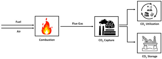
Figure 1.
CO2 post-combustion strategy in largest CO2-emitting industries.
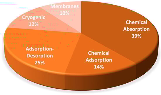
Figure 2.
Distribution of CO2 post-combustion capture technologies in Europe.
Absorption is the most robust and efficient technique for CO2 removal under moderate conditions, especially when using amines, particularly monoethanolamine (MEA). Absorption delivers high removal efficiency and flexibility for various CO2 concentrations, though it requires significant energy for solvent regeneration and is considered the benchmark for large flow rates and standard industrial settings [33,34,35,36,37,38,39]. Adsorption technology is also highly efficient at moderate to high pressures and is best suited for small to medium scales; it is modular, compact, and easy to operate, but has lower continuous capacity and needs frequent regeneration cycles, working well with gases of variable CO2 content. Solid sorbents, including materials like mesoporous silicas [40,41,42,43,44], zeolites [45,46,47,48], microporous carbon [49,50,51,52,53,54], mesoporous carbon [55,56,57,58,59], and metal–organic frameworks (MOFs) [60,61,62,63,64], offer advantages such as high CO2 capacity and lower regeneration energy [65,66]. For instance, structured adsorbent beds have been developed using MOFs to rapidly capture and release CO2. Each of these technologies presents unique advantages and challenges, with ongoing research aimed at improving efficiency, reducing costs, and scaling up for industrial applications. Absorption–desorption [a common technology is Calcium Looping (CaL)] is fundamentally incompatible with moderate temperature and pressure conditions, as it requires extremely high temperatures (600–950 °C) for efficient operation, making it unviable in typical industrial scenarios unless high-temperature processes are already in place. Note that, CO2 capture using adsorption–desorption cycles relies on the ability of certain solid materials (adsorbents) to selectively bind CO2 molecules from a gas mixture (such as air or flue gas) onto their surfaces during an adsorption phase. Once the adsorbent is saturated, a desorption phase is initiated to release the captured CO2, regenerating the adsorbent for reuse in subsequent cycles [5,67,68,69,70]. Cryogenic separation requires extremely low temperatures (below −100 °C), even under moderate to high pressures, only making it suitable for large volumes and high purities. Without intensive refrigeration, it is not effective and therefore cannot be applied under the typical conditions of absorption, adsorption, or membrane technologies. Cryogenic carbon capture cools flue gases to such low temperatures that CO2 desublimates directly from a gas into a solid, offering high capture rates with potentially lower energy consumption [71,72,73,74,75]. Membrane separation is very efficient at moderate to high pressures and ambient temperatures, especially for gases with high CO2 partial pressure; it offers a smaller footprint, modularity, and easy scalability, but may have lower selectivity and yield compared to chemical absorption when CO2 concentrations are low [76,77,78,79,80,81]. As a conclusion, under typical industrial operational conditions, chemical absorption is the most robust and efficient method for CO2 removal at large scales, adsorption is the best technique for modular or lower-flow applications, membrane separation is advantageous for gases with high CO2 partial pressure and compact installations, while CaL and cryogenic separation are not viable unless extreme temperatures are available. By implementing such technologies, Europe aims to achieve its climate goals and transition towards a more sustainable and low-carbon economy. However, each technology has its own set of advantages and challenges, ranging from energy efficiency and cost to scalability and environmental impact.
Quantitative analysis of the environmental impacts of post-combustion carbon capture (PCC) technology using amine-based absorption for CO2 capture reveals several critical aspects. The primary environmental benefit is the significant reduction in CO2 emissions, as these systems can capture more than 90% of CO2 from flue gases in the largest CO2-emitting industries [28]. However, the broader adoption of this technology is limited by its substantial energy requirements, especially for solvent regeneration, which can increase the overall plant energy consumption by 15–30%. This additional energy demand often results in higher indirect emissions, unless renewable energy is used for these auxiliary processes [82]. From a quantitative perspective, the life cycle assessment (LCA) of post-combustion amine-based capture typically indicates that the technology can reduce net CO2 emissions by approximately 75–84% per unit of electricity generated, depending on plant efficiency and capture rate. However, the process also generates environmental burdens such as solvent degradation and disposal, increased water consumption, and the potential emissions of volatile organic compounds and nitrosamines, which are harmful to human health and the environment. Corrosion and equipment degradation are additional operational challenges that can lead to increased maintenance and material replacement, further contributing to the environmental footprint [83]. Adsorption is recognized for its high capture efficiency (typically exceeding 85%) and the potential for sorbent regeneration through pressure or temperature swing cycles. Compared to solvent-based absorption, adsorption avoids issues related to solvent degradation and secondary emissions, thereby offering a cleaner environmental profile. However, the process can be energy-intensive, particularly during thermal regeneration phases [28]. LCA indicates that adsorption-based carbon capture can also significantly reduce greenhouse gas emissions, reducing them by approximately 75–84%, when integrated into fossil fuel-based power systems. Nonetheless, trade-offs with other environmental indicators, such as acidification and eutrophication potential, must be considered in comprehensive sustainability evaluations [83]. Absorption–desorption (CaL) is a technology that is mainly used for capturing CO2 from industrial processes, especially in cement and power plants. Its environmental impact is considered moderate to favorable compared to traditional CO2 capture methods like amine scrubbing. It is observed that, when applied to cement production, CaL technology can significantly reduce greenhouse gas emissions, with potential reductions of up to 74% when used as a tail-end approach (where it captures CO2 from the plant’s exhaust gases) or up to 71% when fully integrated into the cement manufacturing process itself [84]. The main reason for this is that CaL uses abundant and cheap limestone as a sorbent, which is widely available and non-hazardous. The mining of limestone for CaL only has minor environmental effects, similar to those of other mining operations. A key advantage is that the waste sorbent from CaL can be reused in cement manufacturing, which not only reduces waste but also cuts down CO2 emissions from the cement industry. An LCA study reported by Golelli et al. [85] shows that CaL has a moderate environmental impact but clear advantages over many alternative capture technologies. For example, in thermochemical energy storage, CaL emits about 24 kg CO2/MWh, which is lower than the volume emitted by molten salt solar systems (40 kg CO2/MWh). Although building CaL-integrated plants requires more energy, the operational phase is less burdensome due to low limestone impact and reduced water use. From an environmental perspective, cryogenic separation has both strengths and drawbacks. One of its main advantages is the ability to produce high-purity CO2, which is essential for efficient transport and long-term geological storage. However, the process is highly energy-intensive. It requires between 600 and 660 kWh of energy per ton of CO2 recovered in liquid form. This high energy demand can lead to significant indirect greenhouse gas emissions, especially if the electricity used is generated from fossil fuels. Additionally, the infrastructure needed to maintain cryogenic conditions, such as insulated pipelines and specialized compressors, adds to the environmental footprint through material use and construction impacts [28]. In terms of LCA, cryogenic separation generally performs worse than other CO2 capture technologies like chemical absorption or membrane separation. Leung et al. [28] indicate that while cryogenic systems can achieve CO2 recovery rates of 90–95%, their overall environmental burden is higher due to the energy required for cooling and compression. For example, an LCA comparing various capture and storage combinations found that cryogenic separation, when paired with geological storage, resulted in greater environmental impacts than absorption-based systems. Nonetheless, it remains a viable option in scenarios where CO2 concentrations are high and where renewable energy can be used to power the separation process, thereby mitigating some of the associated emissions. Membrane technology is a promising CO2 capture method that avoids the use of chemical solvents, offering a simpler and more compact alternative to traditional absorption. It selectively separates CO2 from flue gases and is well-suited for integration into existing industrial systems. Under optimal conditions, high CO2 concentrations and capture efficiencies above 80% are achievable [28]. However, membranes face challenges such as low gas flux, fouling, and high energy demand for gas compression, which can reduce efficiency and increase emissions. These issues are more pronounced in PCC, where CO2 levels and pressures are lower. From an LCA perspective, membranes show strong potential. According to Leung et al. [28], when combined with geological storage (e.g., saline aquifers), they offer lower environmental impacts than other methods. Although they are still under development and less cost-effective than mature options like amine absorption, membrane systems are attractive for future deployment due to their low environmental footprint and operational simplicity. Ongoing improvements in materials and design are expected in order to enhance their performance and cost-efficiency, supporting their role in sustainable PCC strategies.
Looking ahead, the future strategies for CO2 capture in Europe involve enhancing efficiency and reducing the costs of these technologies. Innovations in materials science, process optimization, and integration with renewable energy sources are key areas of focus. Equally important is the utilization of captured CO2, which is transformed from a waste product into a valuable resource. By converting CO2 into fuels, chemicals, and construction materials, CO2 utilization supports the development of a circular carbon economy and adds economic incentives to carbon capture efforts [86,87,88,89,90]. The most prominent utilization routes currently include the production of renewable methane (e-methane) [91,92,93,94] and methanol (e-methanol) [15,92,95,96], Fischer–Tropsch synthetic fuels [97,98,99,100], olefins [101,102,103], CO2-cured concrete [104,105,106], and the mineralization of industrial waste streams [107,108,109]. Each pathway offers distinct technical and economic advantages and is being explored for integration into various industrial sectors. From a market perspective, CO2 utilization is still in the early stages of commercialization, with most projects operating at pilot or demonstration scales. However, significant growth is anticipated: by 2030, several European projects are expected to produce hundreds of thousands of tons of products annually, supported by public funding mechanisms like the EU Innovation Fund. However, the market is driven by regulatory incentives, evolving carbon pricing, and increasing demand for low-carbon products in sectors such as transportation, chemicals, and construction. Scalability and process integration are key challenges and opportunities. For hard-to-abate sectors like cement production, CO2 utilization can be integrated within existing processes, for example, through mineralization or concrete curing, offering a dual benefit of emission reduction and product enhancement [104,110,111]. In chemical and geothermal applications, modular PCC systems enable flexible deployment and process optimization, allowing CO2 to be utilized close to the emission source or transported via pipeline or ship to centralized hubs for further processing [17]. The establishment of CO2 capture hubs, along with the associated transport infrastructure, promotes economies of scale and reduces investment risks, thereby enabling the implementation of regionally coordinated and interconnected carbon management strategies. Furthermore, the modularization of PCC technologies enhances operational flexibility, facilitating the retrofitting of existing industrial facilities and the integration of CO2 utilization pathways across diverse industrial value chains. In this context, the development of robust regulatory frameworks and the provision of financial incentives will be crucial to accelerating the adoption of these technologies at a continental scale [112,113,114,115].
This review presents an extensive overview of pilot and demonstration units worldwide that were involved in implementing post-combustion CO2 capture strategies in major emitting industries. It also critically assesses the efficiency and environmental implications of the latest technologies used for post-combustion CO2 capture. Additionally, it explores future strategies and innovations aimed at enhancing the capture process, reducing operational costs, and integrating CO2 utilization methods to create value-added products. By examining the advancements and challenges in this field, the review aims to offer insights into the potential pathways for achieving significant reductions in CO2 emissions and contributing to Europe’s climate goals.
2. Pilot and Demonstration Units of CO2 Post-Combustion Capture in Europe
Pilot and demonstration units of CO2 post-combustion capture technologies play crucial roles in advancing carbon capture technology [116,117,118,119], particularly in Europe’s largest CO2-emitting industries [120,121,122,123]. These units serve as essential intermediaries between laboratory research and full-scale commercial deployment, offering several advantages. Firstly, pilot and demonstration units provide a controlled environment to test and optimize CO2 capture technologies. This allows researchers to identify and address potential issues that may not be apparent in smaller-scale experiments. Secondly, these units help in validating the scalability of CO2 capture technologies. By operating at a larger scale than laboratory setups, pilot and demonstration plants can provide critical data on the performance, energy requirements, and operational costs of the technology. This information is essential for conducting techno-economic assessments, which evaluate the feasibility and cost-effectiveness of implementing CO2 capture on a commercial scale. For example, the pilot plant studies often reveal the energy demand and incremental fuel requirements associated with CO2 capture, which are crucial for assessing overall economic impact. Moreover, pilot and demonstration units facilitate the development of regulatory frameworks and industry standards. Regulatory frameworks play a critical role in the successful deployment and long-term effectiveness of CCUS technologies. The establishment of clear legal and regulatory structures is essential to ensure the safe and secure storage of CO2, the protection of public health and the environment, and the overall integrity of CCUS operations. These frameworks provide clarity regarding the rights and responsibilities of all stakeholders, including governmental authorities, operators, investors, and the public, thereby reducing uncertainty and fostering the confidence necessary for investment and project development [124,125]. A robust regulatory environment addresses the entire CCUS value chain, but places particular emphasis on CO2 storage due to its novel and complex legal, technical, and environmental challenges. Key aspects include the definition of property rights and long-term liability for stored CO2, the establishment of criteria for site selection and operational safety, and the management of risks throughout the lifecycle of storage sites, from development to closure [126]. Regulatory frameworks must also ensure that environmental safeguards are in place and that mechanisms for public engagement and consultation are established, which are fundamental for building societal trust and acceptance of CCUS projects. Moreover, comprehensive regulatory reviews are necessary to identify and address gaps or barriers in existing legal systems that could hinder CCUS deployment. This includes adapting or amending existing laws, such as those governing hazardous waste, property rights, and environmental protection, to accommodate the specific requirements of CCUS technologies [116,124]. In some cases, the development of dedicated CCUS legislation may be required to provide a coherent and supportive legal basis for commercial-scale activities. Within the European context, regulatory efforts are advancing through initiatives such as the EU Green Deal and the Net-Zero Industry Act, which aim to simplify and harmonize regulations and support the scale-up of CCUS. Policymakers are focusing on developing integrated value chains for CCUS, addressing technical, financial, and social dimensions [127]. Also, by providing empirical data on the environmental and economic performance of CO2 capture technologies, these units support policymakers in creating regulations that promote the adoption of CCUS solutions. This, in turn, encourages investment in CCUS technologies and helps industries comply with stringent emission reduction targets. From a broader perspective, the successful operation of pilot and demonstration units can boost public and stakeholder confidence in CO2 capture technologies. Demonstrating the viability and benefits of these technologies in real-world settings helps to build trust and support for their widespread adoption. This is particularly important in industries with high CO2 emissions, where the transition to low-carbon technologies is critical for achieving climate goals [128,129,130].
Currently, there are nineteen active CO2 post-combustion capture technology units in Europe that use the absorption technique (CO2_absorption). Figure 3 shows the development of small-scale units (≤1 kton/year) in various European countries, including Sweden, Poland, Denmark, Greece and Romania, each with one pilot-scale facility. There are also five medium-scale (1–100 ktons/year) CO2_absorption facilities located in France (two units), Spain, Norway, and the Netherlands (one unit each). However, the number of large-scale (>100 ktons/year) CO2_absorption installations is low, with six units in total: there are three in Germany, and one each in Poland, Norway, and Latvia. Additionally, there are three CO2_absorption installations in Greece, Norway, and Ireland of an undisclosed scale, with each also possessing one pilot-scale plant.
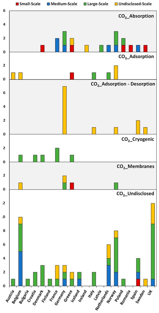
Figure 3.
Distribution of active CO2 post-combustion capture technology units across European countries: CO2_absorption, CO2_adsorption, CO2_adsorption–desorption, CO2_cryogenic, CO2_membranes, and CO2_undisclosed (from bottom to top). Units are categorized by scale: small-scale (red), medium-scale (blue), large-scale (green), and undisclosed-scale (yellow).
Regarding CO2 post-combustion capture technology units based on the adsorption technique (CO2_adsorption), seven units were identified across different scales: one small-scale unit, two large-scale units, and four undisclosed-scale units. Figure 3 indicates that Norway leads in the development of CO2_adsorption units with two units, while Greece, the Netherlands, Belgium, and Austria each have one unit.
In the case of CO2 post-combustion capture technology units based on the adsorption–desorption technique (CO2_adsorption–desorption), twelve units were identified in Europe. Figure 3 shows that Germany leads with seven undisclosed-scale units, Spain has two undisclosed-scale units, Italy has one small-scale unit, Norway has one large-scale and one undisclosed-scale unit, and Sweden has one undisclosed-scale unit.
Regarding CO2 post-combustion capture technology units based on the cryogenic technique (CO2_cryogenic), six large-scale demonstration units have been identified. Figure 3 shows that France, Croatia, Denmark, Greece, and Belgium each have one unit. For CO2 post-combustion capture technology units based on the membrane technique (CO2_membranes), five units have been identified in Europe. Figure 3 shows that Germany (one large-scale and one undisclosed-scale unit) leads in the development of CO2_membranes units. Greece (small-scale), Norway (large-scale), and Belgium (undisclosed-scale) each have one unit.
Currently, there are sixty-two active CO2 post-combustion capture technology units in Europe based on undisclosed techniques (CO2_undisclosed), and comparison between them can be found in Table S2 (see Supplementary Material). Figure 3 illustrates the existence of a single small-scale unit located in Spain. There are thirteen medium-scale CO2 facilities with undisclosed technology in various countries, including Belgium (four units), the Netherlands (three units), Norway (two units), Spain, Germany, Iceland, and the UK (one unit each). The number of large-scale CO2 facilities with undisclosed installations is significantly higher, with thirty-four units globally. Figure 3 shows that large-scale CO2_undisclosed units have been established in Spain, Italy and Croatia, (two units each), Denmark (three units), Belgium (four units), Norway (five units), and other countries like the Germany, the Netherlands, Iceland, Finland, Greece, Poland, Bulgaria and France (one unit each). The UK leads with eight large-scale units. Additionally, there are thirteen undisclosed-scale CO2 facilities, with undisclosed installations in the Netherlands and France (two units each), UK (three units), Germany, Belgium, Norway, Sweden, Greece and Ireland (one unit each). Note that, Germany is emerging as the leading country in the development of CO2 post-combustion capture technology units across various techniques. Other countries like Spain, Belgium, the Netherlands, Norway, the UK, France, and Denmark have made considerable contributions, especially in the undisclosed technique category. Overall, the development of CO2 capture technology units is widespread across Europe, with various countries contributing to different scales and techniques.
The distribution and prevalence of different CO2 PCC technologies across Europe can be attributed to a mix of technological, industrial, economic, and policy-driven factors [131]. First, the choice of technology often depends on the characteristics of local industries and the types of emission sources. For example, CO2_absorption capture is well-established and widely adopted in regions with large-scale power plants or industrial facilities, as it is robust and suitable for high volumes of flue gas. This explains the presence of several large-scale absorption units in countries like Germany, Norway, and Poland, which have significant industrial or energy sectors. In contrast, CO2_adsorption and CO2_adsorption–desorption technologies may be more prevalent where there is a focus on innovation or where pilot and demonstration projects are being pursued. Norway, for example, leads in the development of adsorption units, possibly due to its strong commitment to carbon capture research and its use of natural gas for both domestic energy and export, which creates opportunities for piloting new technologies. Similarly, Germany’s dominance in adsorption–desorption units could reflect both its industrial base and its investment in research and development. CO2_cryogenic and CO2_membranes capture technologies are less widespread, but their presence in specific countries, such as France, Croatia, Denmark, Greece, and Belgium for cryogenic applications, and Germany, Greece, Norway, and Belgium for membrane applications, indicates targeted deployment in industries where these technologies offer particular advantages, such as in niche industrial processes or areas where specific separation requirements exist. On the other hand, the prevalence of CO2_undisclosed technology installations suggests that a significant portion of CO2 capture projects are either proprietary or still in the early stages, making their technical details unavailable. The United Kingdom, for instance, has a large number of large-scale undisclosed units, which may reflect both a strong policy push for CCUS and the presence of diverse industrial sectors.
All the mentioned units involve capturing CO2, but the specific sources differ among them (see Figure 4). It is important to note the various sources of CO2 emissions and the methodologies employed for their capture across different scales. It highlights the diversity of industrial sources, including heat and power plants, cement plants, and waste plants, among others. Each method of CO2_absorption, CO2_adsorption, CO2_adsorption–desorption, CO2_cryogenic, CO2_membranes, and CO2_undisclosed, targets specific sources and scales, ranging from small to large and undisclosed. This comprehensive approach ensures that CO2 emissions from a wide array of industrial activities are effectively captured, contributing to the overall goal of reducing greenhouse gas emissions.
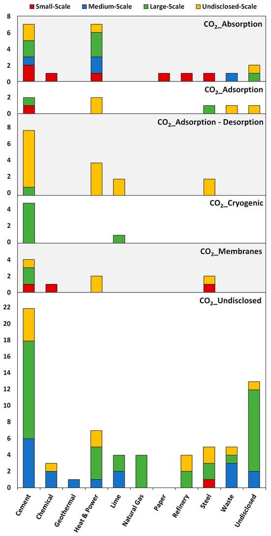
Figure 4.
Distribution of active CO2 post-combustion capture technology units across various industrial sectors in Europe: CO2_absorption, CO2_adsorption, CO2_adsorption–desorption, CO2_cryogenic, CO2_membranes, and CO2_undisclosed. Units are categorized by scale: small-scale (red), medium-scale (blue), large-scale (green), and undisclosed-scale (yellow).
Considering the technology being used, CO2_absorption (Figure 4), devices are installed in the cement industry to assess CO2 emissions at the small scale (two units) and in heat and power plants, paper plants, chemical plants, refinery plants, and steel plants, each with one small-scale unit. At a medium scale, CO2 capture units are installed in paper production facilities, cement plants, and waste-processing installations, each with one unit. At the large scale, CO2 emissions are captured from heat and power plants (three units), cement plants (two units), and undisclosed sources (one unit). Additionally, at an unspecified scale, CO2 sources include heat and power plants (one unit), cement plants (two units), and one unidentified source.
In CO2_adsorption (Figure 4), CO2 emissions from cement plants are captured in one unit at a small scale. At a large scale, CO2 emissions from steel and cement plants are considered within one unit (per plant). At an undisclosed scale, CO2 capture devices are installed in two heat and power plants, in one waste plant, and at one undisclosed source.
In CO2_adsorption–desorption (Figure 4), CO2 emissions from heat and power plants (four units), cement plants (seven units), lime (two units), and steel plants (two units) are considered at an undisclosed scale. Two cement plants have CO2_adsorption–desorption capture technology installed at small and large scales.
In CO2_cryogenic (Figure 4), CO2 emissions from lime plant (one unit) and cement plants (five units) are considered at a large scale.
In CO2_membranes (Figure 4), CO2 emissions from heat and power plants (two units), cement plants (one unit), and waste plants (one unit) are considered at an undisclosed scale. Additionally, CO2 emissions from cement plants (two unit) are considered at a large scale. Three small-scale units are installed, with one in each industry: cement, chemicals and stell.
Figure 4 illustrates the distribution of undisclosed CO2 capture technology across various scales and industries. At a small scale, only one unit is reported in the steel industry [132]. Medium-scale units are predominantly found in cement (five units), waste (three units), lime (two units), and chemical industries (two units), with additional units in heat and power (one unit) and undisclosed sources (two units) [133,134,135,136,137,138,139,140,141,142,143,144,145]. Large-scale applications are most common in cement (twelve units), followed by undisclosed sources (ten units), heat and power (four units), and natural gas (four units), with fewer units in other sectors [146,147,148,149,150,151,152,153,154,155,156,157,158,159,160,161,162,163,164,165,166,167,168,169,170,171,172,173,174,175,176,177,178]. Units of an undisclosed scale are distributed across several industries, with cement (four units) having the highest representation, followed by heat and power, refinery, and steel (two units each). Industries with only one unit are chemicals and waste [160,179,180,181,182,183,184,185,186,187,188,189]. All the installations and projects are presented in Figure 5, Figure 6, Figure 7 and Figure 8; it is possible to observe the distribution of scale, countries, avoided CO2, and the Technology Readiness Level (TRL).

Figure 5.
The small-scale (≤1 ktons/year) post-combustion capture facilities: CO2_absorption:  ; CO2_adsorption:
  ; CO2_membrane:
  ; CO2_undisclosed:
  ; paper pulp:
  ; steel:
  ; magnesite:
  ; cement:
  ; chemical:
  ; oil:
  ; greater color intensity: greater number of units.
; CO2_adsorption: ; CO2_membrane: ; CO2_undisclosed: ; paper pulp: ; steel: ; magnesite: ; cement: ; chemical: ; oil: ; greater color intensity: greater number of units.
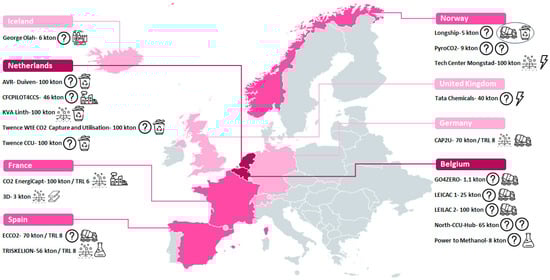
Figure 6.
The medium-scale (1–100 ktons/year) post-combustion capture facilities: CO2_absorption:  ; CO2_undisclosed:
  ; power:
  ; waste:
  ; industry:
  ; cement:
  ; chemical:
  ; geothermal:
  ; greater color intensity: greater number of units.
; CO2_undisclosed: ; power: ; waste: ; industry: ; cement: ; chemical: ; geothermal: ; greater color intensity: greater number of units.
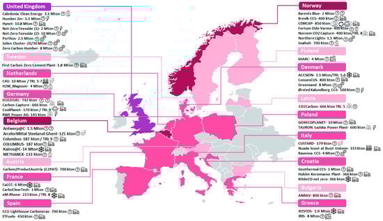
Figure 7.
The large-scale (>100 ktons/year) post-combustion capture facilities: CO2_absorption:  ; CO2_adsorption:
  ; CO2_adsorption–desorption:
  ; CO2_membrane:
  ; CO2_cryogenic:
  ; CO2_undisclosed: ; power:
  ; oil:
  ; waste:
  ; natural gas:
  ; cement/lime:
  ; various:
  ; iron/steel:
  ; greater color intensity: greater number of units.
; CO2_adsorption: ; CO2_adsorption–desorption: ; CO2_membrane: ; CO2_cryogenic: ; CO2_undisclosed: ; power: ; oil: ; waste: ; natural gas: ; cement/lime: ; various: ; iron/steel: ; greater color intensity: greater number of units.
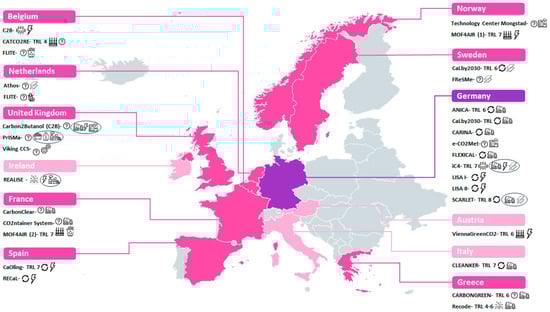
Figure 8.
The undisclosed-scale post-combustion capture facilities: CO2_absorption:  ; CO2_adsorption:
  ; CO2_adsorption–desorption:
  ; CO2_membrane:
  ; CO2_undisclosed:
  ; power:
  ; oil:
  ; waste:
  ; industry:
  ; natural gas:
  ; cement/lime:
  ; ethanol:
  ; various:
  ; iron/steel:
  ; coal:
  ; greater color intensity: greater number of units.
; CO2_adsorption: ; CO2_adsorption–desorption: ; CO2_membrane: ; CO2_undisclosed: ; power: ; oil: ; waste: ; industry: ; natural gas: ; cement/lime: ; ethanol: ; various: ; iron/steel: ; coal: ; greater color intensity: greater number of units.
The application of PCC in these high-emissions industries differs in several key aspects [190,191]. (i) Scale: Large-scale implementation in major industrial facilities requires significant infrastructure and poses greater technical and economic challenges compared to smaller demonstration projects. (ii) Process integration: Integrating CCUS systems into existing industrial processes without disrupting production is crucial for these industries, which often operate continuously and at high capacities. (iii) The integration of renewable energy sources: This integration with PCC technologies is widely recognized as an important strategy for maximizing environmental benefits and advancing the decarbonization of heavy industry. While several demonstration projects have explored such integration, its implementation remains limited in current practice. This is mainly due to a combination of technological, economic, and infrastructural challenges. Key barriers include the high energy demands of PCC processes, which require reliable and continuous power supply, and the variable, intermittent nature of most renewable energy sources. Additionally, many industrial sites lack access to sufficient renewable energy infrastructure or face economic constraints that make additional investments in renewables difficult. Policy support and financial incentives are still evolving and have not yet reached the needed level to encourage widespread adoption. These factors collectively explain why only a small portion of existing PCC technologies have so far been able to integrate renewable energy sources. (iv) Energy penalty: The energy-intensive nature of PCC can significantly impact the efficiency of power plants and industrial processes, requiring careful consideration of the overall energy balance. (v) Impurities: Industrial flue gases often contain various impurities, such as sulfur oxides (SOx), nitrogen oxides (NOx), hydrogen sulfide (H2S), ammonia (NH3), carbon monoxide (CO), mercury (Hg), particulates, and various hydrocarbons, that can interfere with the capture process [68,69,192,193]. These impurities may reduce the efficiency of absorption or adsorption, cause the corrosion or fouling of equipment, dilute the CO2 stream, increase the risk of toxic or explosive hazards, and complicate downstream purification. As a result, specialized treatment and purification steps are necessary to ensure the quality and safety of the captured CO2 stream. (vi) Economic feasibility: The high capital and operational costs of CCUS systems are particularly challenging for industries operating with thin profit margins, requiring innovative financing and incentive structures. (vii) Risk management: Large-scale CCUS projects in these industries involve complex risk factors, including potential impacts on the main process plant, technical uncertainties, and performance assumptions that require thorough due diligence [128,194]. Despite these challenges, the potential for significant CO2 emission reductions makes the implementation of post-combustion CCUS in major emitting industries a critical area for further research, development, and demonstration. Addressing these industry-specific issues will be crucial for the wider adoption of CCUS technologies and achieving global climate goals [125,195].
2.1. Absorption Technology
Absorption is the most widely used, and usually the most cost-effective, commercial technology for CO2 capture, relying on chemical solvents such as monoethanolamine (MEA) to selectively absorb CO2 from flue gas streams, forming a rich solution [196]. This solution is then heated in a regenerator to release the pure CO2 captured, regenerating the absorbent for reuse. The key advantage of absorption is its high CO2 capture efficiency, with some systems achieving over 90% removal. It is a well-developed technology with commercial applications in power plants and industrial processes [197]. The main disadvantages include high energy requirements for solvent regeneration, leading to increased operational costs. Furthermore, solvent degradation and corrosion issues necessitate ongoing maintenance and solvent replacement, contributing to environmental and economic concerns [198]. The literature review identified nineteen units employing chemical absorption technologies. A detailed description of each unit is provided in Section S3 (see Supplementary Material), and a comparison between them can be found in Table S3 (see Supplementary Material).
2.1.1. Small-Scale Units of Absorption Technology
The literature review identified five small-scale units employing chemical absorption CO2 capture technology (see Figure 5). These projects demonstrate the feasibility of chemical absorption in diverse industrial settings, such as paper pulp mills, cement production, magnesite production, and oil refining, with capture capacities of 1 kton/year or less.
One such initiative is the ACCSESS (“Providing access to cost-efficient, replicable, safe and flexible CCUS”) project (2021–2025), coordinated by SINTEF ENERGI AS; this involves CO2 capture from industrial sources, including Stora Enso’s pulp and paper mill in Skutskär, Sweden, and Heidelberg Materials’ cement plant in Górażdże, Poland. Each site aims to avoid 0.666 ktons/year of CO2 using advanced solvent technology from Saipem, combined with a rotating packed bed absorber developed by Prospin and Proceler [199].
Another notable project is ConsenCUS (“CarbOn Neutral cluSters through Electricity-based iNnovations in Capture, Utilization and Storage”), also running from 2021 to 2025. Coordinated by the Technical University of Denmark, it focuses on electrochemical CO2 capture and conversion at industrial sites including Aalborg Portland’s cement factory in Denmark and OMV Petrom’s Petrobrazi refinery in Romania. Each site aims to avoid approximately 0.800 ktons of CO2 per year. The technology enables high-purity CO2 capture and conversion into chemicals such as formic acid and potassium formate, supporting decarbonization efforts in Europe [200].
2.1.2. Medium-Scale Units of Absorption Technology
The literature review identified six medium-scale units (see Figure 6), employing chemical absorption CO2 capture technology. These projects demonstrate the scalability of solvent-based capture methods in industrial applications, with capacities ranging from 1 to 100 ktons/year.
One such project was the CO2 EnergiCapt initiative, led by Leroux et Lotz Technologies in France, which ran from 2011 to 2016. The aim was to capture CO2 from industrial boilers using a solvent-based system with 90% efficiency. It reached TRL 6 and targeted medium-scale emitters like district heating and agri-food industries [201].
Another notable effort is the 3D project (“DMX Demonstration Dunkirk”), which was conducted at ArcelorMittal’s steelworks in Dunkirk, France, from 2019 to 2024. It captured CO2 from blast furnace gases, avoiding 3 ktons of CO2 per year [202].
Currently, the KVA Linth Carbon Capture and Storage (CCS) project, coordinated by the KVA Linth waste-to-energy plant, is located in Switzerland and is running from 2019 to 2025. It captures CO2 from waste incineration emissions, aiming to avoid 100 ktons of CO2 per year [203].
In Germany, the CAP2U (“Capture-to-Use”) project, coordinated by Heidelberg Materials, BASF, and Linde, is located at the Lengfurt cement plant in Germany and is running from 2022 to 2025. It captures CO2 from cement kiln exhaust gases, aiming to avoid 70 ktons of CO2 per year [204].
The TRISKELION project, coordinated by Forestal del Atlántico S.A., is located in Mugardos, Galicia, Spain, and is running from 2023 to 2028. It captures CO2 from a cogeneration plant, aiming to avoid 56 ktons of CO2 per year [205].
In addition to these, the Technology Centre Mongstad (TCM) in Norway stands out as the world’s largest and most advanced facility for testing and improving CO2 capture technologies. Operational since 2012, TCM captures CO2 from industrial flue gases, with a capacity of up to 118 ktons of CO2 per year [206].
2.1.3. Large-Scale Units of Absorption Technology
The literature review identified six large-scale units (see Figure 7) employing chemical absorption CO2 capture technology. These projects highlight the potential of large-scale solvent-based CO2 capture in heavy industries, particularly in the cement and power sectors, with capacities exceeding 100 ktons/year.
The CEMCAP (“CO2 capture from cement production”) project (2015 to 2018), coordinated by SINTEF, focused on evaluating and optimizing four different capture methods, aiming to integrate them into existing cement plants to improve efficiency and reduce costs, with a target capture capacity of 800 ktons of CO2 per year [207].
The CO2Carbon project, coordinated by UP Catalyst OÜ, was conducted from 2022 to 2024 in Latvia and aimed to scale up electrochemical technology. The CO2 source was in cement plants operated by SCHWENK Latvija in Latvia and Akmenės cementas in Lithuania; researchers used Capsol Technologies’ hot potassium carbonate absorption process. The project targeted an annual CO2 avoidance of up to 800 ktons by 2030 [208].
Currently, the Norcem CO2 Capture project (2013 to 2025), led by Norcem AS, is building a full-scale carbon capture facility at its Brevik cement plant in Norway, aiming to capture around 400 ktons of CO2 per year by 2025 (TRL 8–9). The project uses Aker Solutions’ amine-based technology and a heat recovery system to improve efficiency. Captured CO2 will be liquefied and shipped for underground storage [209]. Similarly, the carbon capture project (2022 to 2025) at Rohrdorfer aims to capture 666 tons of CO2 per year at its cement plant in Rohrdorfer, Germany [210].
Beyond cement production, similar efforts have been observed in the power generation sector, where large-scale facilities are also adopting CO2 capture solutions. Presently, the TAURON Łaziska Power Plant is operational on a large scale as a coal-fired power station located in Łaziska Górne, Poland [211]. Another example is RWE Power AG, a major subsidiary of the RWE Group, headquartered in Essen, Germany [212].
2.1.4. Undisclosed-Scale Units of Absorption Technology
This review identified two projects, employing chemical absorption CO2 capture technology, that fall under the category of undisclosed-scale units (see Figure 8). These initiatives showcase the adaptability of chemical absorption in various industrial applications, including power generation, cement production, and heavy industrial processes, despite lacking publicly available data regarding their specific capture capacities.
These include RECODE (“Recycling carbon dioxide in the cement industry to produce added-value additives: a step towards a CO2 circular economy”), an EU-funded initiative that ran from 2017 to 2022 [213], and REALISE (“Demonstrating a Refinery-Adapted Cluster-Integrated Strategy to Enable Full-Chain CCUS Implementation”), coordinated by SINTEF and conducted between 2020 and 2023 [214].
2.2. Adsorption Technology
Adsorption for CO2 capture utilizes solid sorbents to capture CO2 from flue gas streams. These sorbents include zeolites, metal–organic frameworks (MOFs), and activated carbon. Adsorption can occur via physical interactions (physisorption) or chemical bonding (chemisorption), with CO2 being released through temperature or pressure changes in a process known as temperature swing adsorption (TSA) or pressure swing adsorption (PSA/VSA) [215]. Adsorption technology has advantages in terms of lower energy consumption compared to solvent-based absorption. It also offers modularity and flexibility, making it suitable for various industrial applications. However, the cost of high-performance sorbents, sorbent degradation over time, and limited CO2 loading capacity are significant challenges. Moreover, the need for periodic regeneration cycles can lead to process inefficiencies [216]. The literature review identified seven units employing chemical adsorption technologies. Comprehensive descriptions of each unit are available in Section S4 of the Supplementary Material, while a comparative overview is presented in Table S4.
2.2.1. Small-Scale Unit of Adsorption Technology
The literature review identified one small-scale unit (see Figure 5), employing chemical adsorption CO2 capture technology. This initiative demonstrated the feasibility of using advanced solid sorbents in PCC applications at a capacity of less than 1 kton/year.
An example was the CARMOF (“Tailor-Made 3D Printed Structures based on CNS and MOFS Materials for Efficient CO2 Capture”), which was conducted in Greece from 2018 to 2022. It focused on PCC from the cement, steel, and chemical industries, aiming to prevent significant annual CO2 emissions through advanced adsorption technologies [217].
2.2.2. Large-Scale Units of Adsorption Technology
The literature review identified two large-scale units (see Figure 7) employing chemical adsorption CO2 capture technologies. These initiatives showcase the potential of chemical adsorption methods for industrial-scale decarbonization, demonstrating their feasibility in high-emission sectors such as iron and steel.
One of the key initiatives is the C4U (“Advanced Carbon Capture for Steel Industries Integrated in CCUS Clusters”) project (2020–2025), coordinated by University College London; this sees the advancement of two CO2 capture technologies (DISPLACE & CASOH) from TRL 5 to 7 for steel mills. Targeting up to 94% CO2 reduction, it focuses on integration with existing processes, economic and environmental assessment, and deployment in the North Sea Port cluster with ArcelorMittal [218].
Another significant effort is the Nuada Scout project in Italy, developed in collaboration with Buzzi Unicem. The project uses Vacuum Pressure Swing Adsorption (VPSA) with MOFs to capture 1 ton of CO2/day from cement flue gas. Powered by electricity, it separates CO2 using pressure instead of heat, offering a more energy-efficient and cost-effective alternative to traditional methods [219].
2.2.3. Undisclosed-Scale Units of Adsorption Technology
The literature review identified four units employing chemical adsorption CO2 capture technologies that fall under the category of undisclosed-scale units (see Figure 8). These initiatives demonstrate the adaptability of chemical adsorption across diverse industrial applications, including heat and power generation, and waste incineration.
The ViennaGreenCO2 project (operated from June 2018 to 2019) was a pilot initiative focused on developing and demonstrating CCU technologies at the Wien Energie biomass combined heat and power plant in Simmering, Vienna, Austria [220].
An additional project is the CATCO2RE (“Catalytic CO2 Reduction to Solar Fuels and Chemicals”), led by Ghent University and conducted from 2018 to 2023. Focused on developing technologies to convert CO2 into solar fuels such as methane and methanol, it achieved a TRL of 4 [221].
A third initiative, MOF4AIR (“Metal Organic Frameworks Clean Carbon Dioxide from Our Atmosphere”), coordinated by the Université de Mons and running from 2019 to 2025, aimed to develop and demonstrate the performance of MOF-based CO2 capture technologies in power plants and energy-intensive industries. This project includes two European demonstration sites: Site 1 in Norway, which targets CO2 capture from a combined heat and power (CHP) plant to validate the cost-efficiency and reliability of MOF-based carbon capture in the power sector, and Site 2 in France, which focuses on capturing CO2 emissions from a waste incineration plant [222].
2.3. Adsorption–Desorption Technology
Adsorption–desorption CO2 capture is an effective and versatile approach for reducing industrial emissions, utilizing solid sorbents to selectively capture and release CO2 through pressure or temperature changes. This method is particularly suited for flue gases with low to moderate CO2 concentrations and offers advantages such as lower energy consumption and the potential for regeneration and the reuse of sorbents.
A common technology is CaL. CaL is a cyclic CO2 capture technology based on the reversible reaction of calcium oxide (CaO) and calcium carbonate (CaCO3). The process occurs in two main steps: carbonation, where CO2 reacts with CaO to form CaCO3, and calcination, where CaCO3 is decomposed back into CaO and CO2 at high temperatures [68,69]. One of the main advantages of CaL is its high capture efficiency and relatively low cost compared to other methods. The process utilizes abundant and inexpensive limestone, making it economically attractive. Additionally, it has potential integration with cement and steel industries, offering an avenue for utilizing the spent sorbent material integrated into the produced materials [68,69,223]. Notable challenges to this technique include sorbent deactivation over multiple cycles, leading to reduced capture capacity and increased operational costs [224]. The high-temperature requirements for calcination (above 900 °C) result in significant energy consumption, reducing overall process efficiency. The literature review identified eleven units employing adsorption–desorption technologies. Detailed descriptions of each unit can be found in Section S5 of the Supplementary Material, while a comparative summary is provided in Table S5. Note that, the CEMCAP project also implements this technology at a large scale, as previously outlined in Section 2.1.3, targeting a 90% CO2 capture efficiency through retrofittable solutions for cement plants.
Undisclosed-Scale Units of Adsorption–Desorption Technology
The literature review identified eleven facilities (CEMCAP included) employing adsorption–desorption CO2 capture technologies, all categorized as undisclosed-scale units (see Figure 8). These initiatives represent a wide range of applications across multiple industrial sectors, including cement, lime, heat and power, and steel.
The LISA (“Limestone based Absorption of CO2”) I (2008–2013) and LISA II (2013–2017) projects, coordinated by the Institute for Energy Systems and Technology at Technische Universität Darmstadt, were dedicated to exploring CO2 capture using the CaL process [225,226].
In Spain, the CaOling (“Development of postcombustion CO2 capture with CaO in a large testing facility”) project (2009–2013), coordinated by ENDESA Generación SA, aimed to scale up CaL technology to capture CO2 emissions from coal-fired power plants [227].
In Germany, the CARINA (“Carbon Capture by means of an Indirectly heated Carbonate Looping Process”) project (2010–2017), coordinated by the Institute for Energy Systems and Technology at Technische Universität Darmstadt, concentrated on the development of an indirectly heated carbonate looping process to enhance the efficiency of CO2 capture from industrial flue gas streams [228].
In Germany, the ANICA (“Advanced Indirectly Heated Carbonate Looping Process”) project (2019–2022), coordinated by Technische Universität Darmstadt, focused on the development of an advanced indirectly heated carbonate looping technology for efficient CO2 capture in lime and cement manufacturing processes [229].
In Spain, the RECaL (“Novel calcium looping CO2 capture process incorporating sorbent reactivation by recarbonation”), carried out between 2012 and 2015, focused on validating an innovative sorbent regeneration method for CO2 capture systems using CaL. Its goal was to improve the efficiency and cost-effectiveness of CaL technology by integrating sorbent reactivation through recarbonation [230].
In Germany, the SCARLET (“Scale-up of Calcium Carbonate Looping Technology for Efficient CO2 Capture from Power and Industrial Plants”), conducted between 2014 and 2017 and funded by Horizon 2020, was coordinated by the Technology Department at Technische Universität Darmstadt. The project focused on scaling up CaL technology for CO2 capture in the cement industry [231].
In Germany, the FlexiCaL project (“Development of flexible coal power plants with CO2 capture by Calcium Looping”), running from 2016 to 2019 and funded by the European Union’s Research Fund for Coal and Steel, focused on the design of an innovative CCS plant incorporating CaL technology. Key objectives included analyzing the dynamic behavior and controllability of the CaL process, developing a comprehensive control strategy for cement plant integration, and evaluating the plant’s capability to respond to load variations and deliver ancillary grid services [232].
In Italy, the CLEANKER project (“CLEAN clinKER production by Calcium looping process”) project (2017–2023), coordinated by the Laboratory of Energy and Environment in Piacenza, also aimed to demonstrate the application of the CaL process for CO2 capture in the cement sector. Its central focus was the design, construction, and operation of a CaL demonstration unit at the Buzzi Unicem cement plant [233].
Currently, in Germany and Sweden, the CaLby2030 (“Calcium Looping to Capture CO2 from Industrial Process by 2030”) project is underway. Coordinated by the Agencia Estatal Consejo Superior de Investigaciones Científicas, CaLby2030 is a European project funded under the Horizon Europe programme. Its goal is to pave the way for the commercial deployment of CaL technology using circulating fluidized bed reactors by 2030 [234].
2.4. Cryogenic Technology
Cryogenic CO2 capture represents an innovative and energy-intensive approach to reducing industrial emissions by leveraging low temperatures to separate and liquefy CO2 from flue gases. This method is particularly effective for streams with high CO2 concentrations, achieving high purity and recovery rates. Cryogenic CO2 capture involves cooling flue gases to very low temperatures, condensing CO2 into a liquid phase for separation. This method is particularly suitable for processes requiring high-purity CO2, such as enhanced oil recovery and industrial gas supply. The main advantage of cryogenic separation is its ability to produce high-purity CO2 without requiring chemical sorbents or complex regeneration cycles [235]. Despite this, this method is highly energy-intensive due to the extreme cooling requirements, usually making it less economically feasible for large-scale applications. The capital investment needed for cryogenic infrastructure and the challenges of handling dry ice formation further complicate implementation [236]. The literature review identified six units employing cryogenic technologies, all categorized as large-scale units (see Figure 7). Section S6 of the Supplementary Material provides detailed descriptions of each unit, while Table S6 offers a comparative overview.
Large-Scale Units of Cryogenic Technology
Several innovative projects are utilizing Air Liquide’s Cryocap™ technology to capture CO2 emissions and contribute to decarbonization goals across different industries. Cryocap™ is an innovative carbon capture technology developed by Air Liquide that utilizes cryogenic processes to separate and purify CO2 from industrial gas streams. The process leverages extremely low temperatures to condense CO2 into a liquid or solid form, enabling efficient separation from other gases. It is particularly suited for industries such as cement production, refineries, and hydrogen production.
Currently, the Kairos@C project, coordinated by Air Liquide and BASF, is located at the Port of Antwerp in Belgium. It captures CO2 emissions from industrial sources such as hydrogen, ethylene oxide, and ammonia production. The project began in 2020 and is set to conclude in 2025. It is expected to avoid approximately 1.5 Mtons of CO2 emissions per year [237].
Presently, the eM-Rhône project, led by Elyse Energy, is located in Salaise-sur-Sanne, France, and is running from 2023 to 2027. It captures CO2 from a cement plant using Cryocap™ FG technology, avoiding approximately 100 ktons of CO2 emissions per year [238].
Similarly, the CaLCC (“First industrial-scale carbon capture for lime production integrated with transport of CO2 to coastal hub and shipping to geological storage in the North Sea”) project, coordinated by Chaux et Dolomies du Boulonnais, aims to decarbonize lime production at the Réty site in France. Running from 2023 to 2027, it targets the capture of approximately 600 ktons of CO2 per year using Air Liquide’s Cryocap™ FG technology. The captured CO2 will be transported to the Port of Dunkirk and shipped for geological storage in the North Sea [239].
Another project utilizing Air Liquide’s Cryocap™ FG technology is the KOdeCO net-zero project (2023–2028), led by Holcim. It aims to transform the Koro-mačno plant in Croatia into the first net-zero cement facility in the Mediterranean, with a planned annual CO2 capture of approximately 366 ktons using the same advanced process [240].
Another notable initiative is the IFESTOS (“TITAN’s pioneering carbon capture project towards zero carbon cement and concrete”) project, led by TITAN Cement Group, which captures CO2 from cement kilns at the Kamari plant near Athens, Greece. It aims to avoid 1.9 Mtons of CO2 annually by retrofitting kilns with cryogenic capture technology. The project is running from its initial phase to final operation between 2025 and 2029 [241].
Furthermore, a notable initiative is the ACCSION project, coordinated by Air Liquide and Cementir Holding Group (via Aalborg Portland), which captures CO2 from the Aalborg cement plant in Denmark. It aims to avoid 1.5 Mtons of CO2 annually, with operations running from 2024 to 2029 [242].
2.5. Membranes Technology
Membrane-based post-combustion CO2 capture relies on the selective permeation of CO2 through polymeric or inorganic membranes. Gas separation occurs due to differences in diffusion rates, enabling CO2 to be concentrated on one side of the membrane while the remaining flue gases are expelled. Membrane technology is appealing due to its compact design, scalability, and lower energy requirements compared to absorption-based technology [215]. It also eliminates the need for chemical solvents, reducing environmental concerns. Despite this, membranes suffer from limitations such as lower selectivity and permeability, which impact efficiency and economic viability [243]. Membrane degradation over time, susceptibility to flue gas impurities, and the need for high-pressure operations further add to the challenges of widespread adoption [244]. The literature review identified four facilities employing membrane-based CO2 capture technologies, demonstrating varying scales of implementation, from small to large units. The literature review identified four units employing cryogenic technologies. Comprehensive unit descriptions are available in Section S7 of the Supplementary Material, with a comparative summary presented in Table S7. It should be noted that the CEMCAP project, as referenced in Section 2.1.3, implements this technology at commercial scale with 90% CO2 capture efficiency through retrofittable cement plant applications.
2.5.1. Small-Scale Unit of Membrane Technology
The literature review identified one small-scale unit (see Figure 5) utilizing membrane-based CO2 capture technology, the CARMOF (“New process for efficient CO2 capture by innovative adsorbents based on modified carbon nanotubes and MOF materials”), coordinated by TITAN Cement. This unit sourced CO2 from cement production and achieved an annual avoidance of 0.350 ktons of CO2. Located in Athens, Greece, the project ran from 2018 to 2021 [245].
2.5.2. Large-Scale Unit of Membrane Technology
The literature review identified one large-scale unit (see Figure 7), employing membrane-based CO2 capture technology. This was the one produced by CoolPlanet Technologies. Operating in Germany, CoolPlanet Technologies applies membrane technology for CO2 capture in the cement sector. This large-scale unit, with a capacity exceeding 10 ktons per year, utilizes the PolyActive™ membrane and achieves a TRL of 9 [246].
2.5.3. Undisclosed-Scale Units of Membrane Technology
The literature review identified two facilities (see Figure 8), utilizing membrane-based CO2 capture technologies, under the category of undisclosed-scale units.
An example was the iC4 (“Integrated Carbon Capture, Conversion, and Cycling”) project, led by Wacker Chemie AG; this focused on transforming excess renewable electricity into synthetic methane using captured CO2. Running from 2012 to 2015, the initiative aimed to enhance the methanation process by evaluating around 250 catalyst systems, with particular attention paid to reaction mechanisms and surface interactions. As part of the project, Wacker Chemie AG also developed specialized membranes for CO2 separation from waste gas streams, which were tested in collaboration with partners like Linde AG [247].
Another example was the C2B (“CO2 capture and utilization based on a membrane process”) project, coordinated by Solvay Carbonate France. The project aimed to capture CO2 from post-combustion flue gases using membrane contactor technology and convert it into sodium bicarbonate. The CO2 source was flue gas, and the emissions avoided amounted to several kilotons per year. The project took place in France from December 2013 to mid-2017 [248].
3. Techno-Economical Assessment Studies on Post Combustion Carbon Capture
PCC technologies are essential for mitigating CO2 emissions from existing fossil fuel power plants and industrial sources. As an overview, absorption remains the dominant commercial technology, but its high energy demand motivates research into alternative methods [249,250]. CaL offers promising cost reductions but requires advancements in sorbent stability to improve viability compared to amine-based systems [68,69]. Adsorption and membrane technologies present opportunities for energy savings but need improvements in advanced materials, with lower degradation rates allowing for cost reductions in equipment and enhancing performance [251,252,253]. Cryogenic separation, despite its challenges, remains relevant for specific high-purity CO2 applications, being a promising candidate for post-combustion CO2 mitigation, especially in scenarios where cold energy sources are available [254]. Future research is currently focused on hybrid approaches that integrate multiple PCC technologies to optimize efficiency and cost-effectiveness [255,256]. Additionally, advancements in materials science, process optimization, and integration with renewable energy sources can enhance the feasibility of PCC on a global scale.
Some techno-economic analysis (TEA) studies were reviewed. They focused mostly on the use of the five strategies, explored above, in European countries. These studies highlight the complexities and trade-offs involved in selecting and implementing PCC technologies. Key factors considered include economic, process, energy, and environmental data. The research spans diverse industries such as pulp mills, power plants, aluminium production, and cement manufacturing, demonstrating the wide-ranging applicability of PCC technologies. The findings reveal that while some technologies show promise in specific applications, there is no one-size-fits-all solution. Each method has its strengths and limitations, often presenting a trade-off between efficiency and cost. The studies also emphasize the importance of continuing research and development to improve the economic viability and energy efficiency of these technologies, as well as the need for supportive policies and investments to accelerate their adoption in industrial settings.
It is important to note that the values of Capital Expenditures (CAPEX) and Operational Expenditures (OPEX) cost update for 2024 were performed using the appropriate Chemical Engineering Plant Cost Index (CEPCI) [257], where Current CAPEX = Historical CAPEX * (2024 CEPCI/Historical CEPCI). Other costs, such as the cost of electricity, raw materials, utilities, and capturing materials, were updated using inflation values available from the US Department of Labor, while dollar to euro conversions were set at USD 1.00 = EUR 0.97.
Absorption remains the dominant commercial technology, particularly when using MEA and the Chilled Ammonia Process (CAP). The Östrand Pulp Mill in Sweden, which illustrates the trade-offs between different methods, was reported by Subramani [258]. MEA, a widely used solvent, has a capture cost of 40–45 EUR/ton of CO2 and energy consumption of 3.50–3.95 GJ/ton of CO2, for a carbon capture rate of 2030.64 kton/year. In contrast, CAP, which operates at lower temperatures and has lower solvent degradation, incurs a capture cost of 79–88 EUR/ton of CO2 but benefits from a reduction in energy consumption (2.18–2.30 GJ/ton of CO2). The absorption process in CAP captures up to 99% of CO2, whereas MEA reaches a maximum efficiency of 94%. Despite its lower CAPEX and OPEX, MEA suffers from solvent degradation, requiring a make-up rate of 1.0–1.6 kg/ton of CO2 captured, whereas CAP’s solvent is more stable. It should be noted that CAPEX was determined using a detailed, bottom-up method, factoring in equipment, engineering, contingencies, and owner’s costs, with results then annualized over 30 years at a 10% interest rate. OPEX included fixed costs like labour and maintenance, plus variable costs such as steam, electricity, water, and solvent replacement. Additionally, CAP’s higher CO2 loading reduces solvent recirculation rates, cutting energy demand. The choice between these methods could depend on site-specific energy integration and cost considerations, with MEA requiring significant low-pressure steam, while CAP is more energy-efficient but requires additional refrigeration and the handling of solid precipitates, with the ability to operate with excess waste heat [258].
PCC, using MEA absorption, is another method adopted for reducing CO2 emissions in natural gas combined cycle (NGCC) power plants. In Uzbekistan, Kamolov et al. [259] conducted a feasibility study on a 450 MW NGCC plant. Their research shows that integrating MEA-based PCC can capture 1048 kton/year of CO2 at a 90% capture efficiency. However, this process reduces plant efficiency from 55.8% to 46.8% due to the energy demand of solvent regeneration, which requires 3.97 GJ/ton of CO2. The economic indicators of this study were evaluated using specific criteria related to CAPEX and OPEX, as well as levelized cost metrics [levelized cost of electricity (LCOE)]. For CAPEX, the analysis considered the total capital cost, which includes both direct costs (such as equipment and installation) and indirect costs (such as engineering and contingency). This total was then annualized using the Capital Recovery Factor, which accounts for the plant’s economic lifetime and the assumed interest rate, yielding the annualized capital cost. Additionally, the costs of CO2 compression units and pipeline infrastructure were included in the CAPEX evaluation. OPEX was divided into fixed and variable components. Fixed OPEX was estimated as 3% of the total capital cost. Variable OPEX included the cost of electricity consumption (used for the reboiler, compressors, and blowers), solvent makeup (MEA), cooling water, and fuel. The steam used for solvent regeneration was converted into an equivalent electricity cost to reflect its impact on operational energy demand. To assess overall economic viability, LCOE data was calculated. The total cost of CO2 capture, compression, and transport is approximately 59 EUR/ton, leading to a 45% increase in the LCOE, which ascends from 50 EUR/MWh to 72 EUR/MWh. To achieve these cost outcomes, several operational steps are implemented in the process. The flue gas treatment involves pre-cooling to 40–50 °C, compression, and CO2 absorption in an MEA-based solvent, followed by multi-stage compression up to 12 MPa. A six-stage compression system with intercooling reduces energy demand, while a triethylene glycol dehydration unit ensures pipeline-quality CO2. This is then heated in a regenerator to release pure CO2, which is compressed and transported via pipelines for enhanced oil recovery or underground storage [259].
A study of a biomass-fired power plant in the UK using piperazine (PZ)-based absorption revealed substantial energy savings and cost reductions compared to conventional MEA-based systems, as reported by Ren et al. [196]. The study evaluated different process configurations, with the most efficient setup achieving a CO2 capture efficiency of 90% and solvent energy consumption of 3.97 GJ/ton of CO2 using 40 wt% PZ. This represents an energy saving of 1.01 GJ/ton of CO2 compared to conventional 30 wt% MEA-based capture. The lowest CO2 capture cost of 55.8 EUR/ton of CO2 was achieved using a combination of absorber intercoolers, advanced flash strippers, side stream extraction, and a supercritical CO2 compression unit. This configuration led to a 19.5% cost reduction compared to the standard PZ-based PCC process. For economic evaluation, CAPEX was estimated using a software application (Aspen Process Economic Analyzer V15 (2025)), which provided detailed cost breakdowns of major equipment such as absorbers, strippers, compressors, and heat exchangers. The OPEX was divided into fixed and variable components. Fixed operation and maintenance (O&M) costs were assumed to be 5% of the total CAPEX, while variable O&M costs included electricity, cooling water, make-up water, and solvent replacement costs, being calculated using utility consumption data and market prices. The results show that OPEX was significantly influenced by electricity and solvent consumption, with electricity costs constituting over 80% of total OPEX. The study concluded that optimizing stripper pressure to 7 bar and solvent concentration to 37.5 wt% for standard PCC and 32.5 wt% for advanced flash stripper configurations could further reduce capture costs by 32.4% [196].
Adsorption technologies, evaluated in a steam reforming plant in Norway, present opportunities for cost-effective CO2 capture, as reported by Subraveti et al. [260]. This study evaluates the techno-economic performance of a four-step vacuum swing adsorption (VSA) process for PCC from steam–methane reformer (SMR) flue gas. Note that it uses key economic indicators such as CAPEX and OPEX. CAPEX includes equipment, installation, and adsorbent costs, while OPEX covers maintenance, labour, electricity, and adsorbent replacement. The analysis also considers CO2 purity, recovery, energy use, and productivity. The performances of three adsorbents (Zeolite 13X, UTSA-16, and IISERP MOF2) are compared against a baseline MEA absorption process. The baseline comparison reveals that the MEA-based absorption process costs 66.6 EUR/ton of CO2 avoided. In contrast, the VSA process using Zeolite 13X costs 90.9 EUR/ton, UTSA-16 costs 104.9 EUR/ton, and IISERP MOF2 costs 73.0 EUR/ton. The higher costs for VSA are primarily due to the high costs of UTSA-16 and IISERP MOF2 adsorbents, the significant energy consumption required for vacuum pumps, and the increased CAPEX resulting from the need for multiple columns and vacuum pumps. A major factor influencing the TEA of VSA systems is the regeneration of adsorbents. This process is highly dependent on the efficiency of vacuum pumps, which tends to decline significantly at the deep vacuum levels required to achieve high CO2 purity and recovery. As a result, energy consumption increases, along with CAPEX and OPEX. Additionally, the cost and long-term stability of the adsorbents, particularly MOFs, are critical considerations. While MOFs offer excellent separation performance, their high production costs and uncertain scalability may hinder practical application. To enhance the cost-effectiveness of VSA technology, it is essential to develop more affordable and efficient adsorbents and to optimize process design. Improving vacuum pump efficiency and refining the overall system could help reduce both energy use and capital investment. Overall, although VSA shows promise as a CO2 capture technology, further advancements in materials and process engineering are needed to make it a competitive alternative to MEA-based absorption [260].
CaL was explored in power plants in Norway by Fu et al. [261], offering high capture rates but at a higher cost compared to MEA-based systems. Two configurations were studied at the SINTEF Energy Research in Norway: a simpler Case 1A (natural calcite) with a net efficiency of 44.5% and a more advanced Case 3A (synthetic CaO) achieving 50.9% efficiency. The CO2 capture efficiency for both cases exceeds 92%, which is slightly higher than MEA’s 90.5%. In the study, the techno-economic performance of CaL processes for CO2 capture from NGCC power plants was assessed using several key indicators. CAPEX was estimated using equipment sizing and cost models, especially for key units like the carbonator and calciner, based on CEMCAP data. OPEX was split into fixed (labour, maintenance) and variable (fuel, water, sorbents) factors, with sorbent cost determined based on CaO prices. Two main metrics were used: LCOE and CO2 avoided cost. LCOE was calculated by dividing total annual costs (CAPEX, OPEX) by net power output, using an 8% discount rate over 25 years. This metric reflects the EUR/MWh cost of electricity, enabling comparison between CaL, MEA, and a reference plant without capture. A critical factor influencing these economic indicators is the sorbent regeneration process. In CaL systems for CO2 capture, sorbent regeneration refers to the process of restoring CaO from CaCO3 in the calciner. This step is essential to maintain the sorbent’s reactivity and ensure continuous operation. However, sorbent regeneration presents several challenges that impact the techno-economic performance of the system. One major limitation is the degradation of the sorbent over multiple cycles, which reduces its CO2 capture capacity. This degradation necessitates frequent replacement (make-up) of the sorbent, increasing OPEX. Additionally, the calcination process requires high temperatures and significant energy input, often supplied through oxy-combustion, which adds complexity and cost to the system. From a techno-economic perspective, these factors contribute to higher CAPEX and OPEX. The need for large and specialized equipment (like calciners and solid–solid heat exchangers), combined with the energy penalty from regeneration, results in a higher value of CO2 avoided compared to more mature technologies like MEA-based capture. Therefore, improving sorbent stability and regeneration efficiency is critical to making CaL systems economically competitive. These technical limitations are directly reflected in the economic and performance metrics obtained in this study. The CO2 avoided cost for CaL ranges from 102 to 113 EUR/ton of CO2, significantly higher than the 45–59 EUR/ton of CO2 for MEA-based capture, making it less competitive [261]. Case 3A, using synthetic CaO sorbent and solid–solid heat exchange, improves energy efficiency but at the cost of high capital investment. CO2 capture efficiency exceeds 92%, being slightly higher than the MEA benchmark at 90.5%. However, CO2 purity is lower for CaL (94.8–96.6%) compared to MEA’s 99.9%, which may increase transport and purification costs. OPEX for CaL are also substantial, mainly due to higher sorbent make-up costs and energy demand, leading to a LCOE of 86–90 EUR/MWh, compared to the value of 71 EUR/MWh for MEA [261].
Cryogenic carbon capture processes are evaluated in coal-fired power plants in the Netherlands and cement plants in Italy by Rubinaccio [262]. These methods demonstrate high CO2 removal efficiency and competitive costs, particularly when integrated with liquefied natural gas regasification to utilize cold energy. In the Netherlands, the cryogenic CO2 capture process was evaluated using dynamically operated packed beds, achieving over 99.9% CO2 removal when the initial bed temperature was set at −150 °C. When applied to a 600 MW coal-fired power plant in a way that produces 6520 kton of CO2, this process results in CO2 avoidance costs of approximately 69.26 EUR/ton of CO2. The capture efficiency is highly dependent on flue gas CO2 concentration, with lower concentrations significantly increasing costs. Costs reach up to 134 EUR/ton of CO2 at a 5% CO2 content. The system’s pressure drop also plays a crucial role, as increased resistance raises operational expenses. Compared to alternative technologies, amine scrubbing presents similar costs (~75 EUR/ton), but it is heavily dependent on the availability of low-cost steam [262]. In Italy, research assessed the use of a cryogenic carbon capture TEA in cement production to evaluate its feasibility as an alternative to conventional methods such as amine absorption. The process, simulated in Aspen Plus, achieved 90% CO2 capture efficiency with a purity exceeding 99.99%. The core technology relies on desublimation at −115 °C, where CO2 is separated from flue gas in a cryogenic column. The cost of avoided CO2 was estimated using key performance indicators, showing competitive economics when compared to amine-based absorption or CaL, ranging between 65 EUR/ton of CO2 and 124 EUR/ton of CO2 depending on the cost of electricity. Unlike solvent-based methods, cryogenic carbon capture does not require chemical handling or significant steam input, making it a promising option for industries seeking solvent-free capture solutions. However, high capital costs with compressors, blowers, and pumps accounting for 69% of the CAPEX cost, high energy demand for refrigerant compression, and the low TRL remain barriers to widespread adoption. Note that CAPEX was estimated through detailed equipment cost correlations based on size and type. The total capital investment included installed equipment costs, process contingencies (30%), engineering, procurement and construction (14%), and project contingencies (20%), yielding the Total Overnight Cost. OPEX was divided into fixed and variable components. Fixed costs included labour, maintenance, and insurance, while variable costs were based on process simulation results and included electricity, steam, refrigerated water, and CO2 transport and storage. Electricity consumption, driven by the refrigeration loops, was the dominant contributor to OPEX. Future improvements in equipment design and refrigerant efficiency could further enhance its economic feasibility, making cryogenic carbon capture a better solution for cement plants, particularly where electricity-driven capture is preferred over heat-based methods [262].
Membrane carbon capture in Switzerland using nanoporous single-layer graphene membranes shows competitive energy efficiency and scalability, as reported by Micari et al. [263]. This study evaluated the economic performance of a carbon capture process using advanced graphene membranes. To achieve this, the researchers looked at two main types of costs: CAPEX, which includes the price of equipment like membranes and pumps, and OPEX, which includes electricity and maintenance. The optimized two-stage process with retentate recycling achieved a 90% CO2 capture efficiency, with a capture cost ranging from 36.6 to 47.4 EUR/ton of CO2 for flue gases containing 13.5% and 10% CO2, respectively. The energy penalty was 1.53 GJ/ton of CO2 for lower CO2 concentrations and 1.24 GJ/ton of CO2 for higher concentrations, making membranes highly competitive with absorption-based systems. For steel and cement industries, where CO2 concentrations reach 25%, capture costs ranged from 32.8 to 53.9 EUR/ton of CO2, depending on electricity prices (0.08–0.17 EUR/kWh). Unlike solvent-based capture, membranes eliminate chemical handling and regeneration energy losses, potentially making them more cost-effective and low-energy CO2 capture solutions for decentralized applications and industrial retrofitting. However, challenges remain in membrane fabrication costs (570 EUR/m2) and large-scale industrial deployment [263].
The hybrid approach combining membrane and amine-based PCC technologies offer a promising solution to enhance CO2 capture efficiency while reducing energy consumption and operational costs, as reported by Wang et al. [197]. This method leverages the strengths of both technologies to optimize the overall capture process. In Germany, a comparative analysis of three CO2 capture methods was applied in an iron and steel plant, with an annual CO2 capture capacity of approximately 3500 kton/year. The economic indicators were conducted using several key criteria and metrics. CAPEX and OPEX were estimated following established methodologies, such as those proposed by Peters and Timmerhaus, and further refined in projects like CAESAR and CEMCAP. CAPEX was typically broken down into direct and indirect costs, while OPEX was divided into variable and fixed components. The economic performance was primarily assessed using two indicators: the cost of CO2 captured, and the LCOE. These metrics were calculated using a discounted cash flow approach, ensuring consistency and comparability across different capture technologies and deployment scenarios. The first method, using membrane-based separation, demonstrates the highest CO2 avoidance rate (represents the proportion of CO2 emissions that are avoided compared to a reference or baseline scenario) of 60.4%, costing 54.26 EUR/ton of CO2 due to its efficient energy integration. However, its CAPEX remains significant, with an equipment cost of 92.3 MEUR. It is important to note that, despite its strong performance, membrane-based separation technologies still face significant technical and economic limitations. The intrinsic properties of membrane materials impose a trade-off between permeability and selectivity, which restricts the efficiency of CO2 separation. To achieve industrial-scale performance, very large membrane surface areas are required, significantly increasing capital costs. Moreover, the need for compressors and vacuum pumps to maintain sufficient driving force for gas separation can lead to a substantial increase in electricity consumption. These factors must be carefully considered when evaluating the long-term viability of membrane-based CCUS systems. The second approach, using MEA absorption, achieves a CO2 avoidance rate of 39%, costing 43.92 EUR/ton of CO2 but suffers from high energy regeneration solvent, requiring 3.60–4.00 GJ/ton of CO2 for solvent regeneration. Despite its maturity, the MEA system’s additional CO2 emissions from steam generation lower its net efficiency. The third alternative, a hybrid system combining MEA and membrane technologies, balances the advantages of both methods, reaching an intermediate CO2 avoidance rate of 47.3% while optimizing energy and operational costs. The economic assessment highlights that the hybrid approach reduces overall capture costs to around 8.57 EUR/MWh, slightly outperforming MEA at 8.59 EUR/MWh, while the membrane system reaches 9.59 EUR/MWh [197].
Overall, the studies underscore the importance of ongoing research and development, process optimization, and supportive policies to enhance the economic viability and adoption of PCC technologies across different industrial applications. Each technology presents unique advantages and limitations, necessitating the adoption of a tailored approach based on specific site conditions and integration opportunities. Note that the economic analysis of PCC technologies reveals significant variations in costs across different studies.
Based on this analysis, we can present the main findings from the economic analysis of different PCC studies in Europe (see Table 1). The findings are as follows. (i) Economic Data: The economic analysis reveals significant variability in CAPEX and OPEX costs across different CO2 capture technologies. CAPEX ranges from approximately 7.93 (Ren et al. [196]) to 55.74 (Subraveti et al. [260]) EUR/ton, while OPEX spans from 7.06 (Rubinaccio [262]) to over 65.74 (Fu et al. [261]) EUR/ton. Electricity, raw material, utilities, capture equipment and LCOE costs also vary widely, indicating that economic feasibility is highly dependent on the specific technology and scale of implementation. (ii) Process Data: Most studies employ absorption-based technologies, particularly MEA, with capture rates typically around 90%. Other methods such as adsorption, cryogenic, membrane, and CaL are also represented, with CaL showing the highest capture capacity. This diversity reflects ongoing innovation and optimization in CO2 capture processes. (iii) Energy Data: Energy consumption (based on solvent regeneration) for CO2 capture ranges from approximately 1.37 (Micari et al. [263]) to 4.00 (Wang [197]) GJ/ton. Although global data on energy efficiency is limited, existing studies suggest that the integration of CCUS technologies allows for a reduction in the energy penalty. (iv) Environment Data: Carbon tax values can reach up to 120 EUR/ton (Subramani [258]), and CO2 capture prices vary significantly, from around 36.56 (Micari et al. [263]) to 112.63 (Fu et al. [261]) EUR/ton. Carbon emissions per MWh are generally low, especially for membrane and absorption technologies, indicating their potential for reducing environmental impact. Overall, these studies highlight the economic complexity of implementing technologies, which require substantial investments in both CAPEX and OPEX expenses. While CO2 capture is a vital step toward reducing emissions, the economic viability and efficiency of these technologies remain key challenges for widespread adoption.

Table 1.
Review of economic analysis results of several PCC studies.
For the industries responsible for the highest CO2 emissions, future strategies include the development of advanced PCC technologies using next-generation solvents, the exploration of solid sorbents [264], and the investigation of CaL technologies [69]. In the cement industry, for example, waste heat recovery from kilns can be used to power carbon capture systems, helping to reduce additional energy demands. Other important strategies involve integrating CCUS solutions, designing net-zero cement plants, and developing low-carbon cement alternatives. Similarly, the steel sector, which accounts for approximately 7–9% of global CO2 emissions, is pursuing a variety of strategies to reduce its environmental impact. These include transitioning from coal-based blast furnaces to hydrogen-based direct reduction processes and retrofitting existing blast furnaces with PCC technologies, both of which are key steps [265]. In parallel, the refining industry is addressing its emissions through a different set of technological solutions. Refineries, which contribute around 4% of global anthropogenic CO2 emissions, are implementing measures such as retrofitting with carbon capture systems, process integration, the use of advanced solvents and membranes, and the production of low-carbon hydrogen. A major focus is on upgrading existing units with more efficient capture systems and developing integrated solutions that share equipment across multiple units [266].
As these industrial sectors innovate and align their actions with Europe’s climate goals, CCUS technologies will play a crucial role in reducing emissions while maintaining economic competitiveness. Integrating these strategies into long-term planning will enable heavy industries to make significant progress toward carbon neutrality by the mid-century. The success of these initiatives will depend on strong investments in research and development, supportive public policies, and technological infrastructure.
4. Conclusions and Outlook
PCC has been identified as a pivotal technology in the decarbonization of heavy industry and energy production, offering a practical pathway to significantly reduce CO2 emissions from sectors that are otherwise difficult to mitigate. By enabling the separation of CO2 from flue gases after fossil fuel combustion, PCC allows existing industrial and power generation facilities, such as those in steel, cement, and chemicals, to lower their emissions without the need for complete infrastructure overhaul or plant closure. This retrofit capability is particularly valuable in Europe, where legacy assets and the urgency of climate targets necessitate solutions that can be rapidly deployed at scale.
The variety of pilot and demonstration initiatives throughout Europe reflects substantial ongoing innovation in alternative PCC technologies, such as CO2_adsorption, CO2_adsorption–desorption processes (namely CaL), CO2_cryogenic separation, and membrane-based CO2 systems (CO2_membrane). Each technology offers trade-offs between capture efficiency, energy use, and environmental impact. CO2_absorption, while mature and effective, imposes significant energy penalties and generates hazardous waste. CO2_adsorption and CO2_membrane technologies show promise in terms of lower energy use and reduced waste, but face challenges in scalability and material durability. CaL provides a balance between efficiency and energy penalty, but requires management of solid waste. CO2_cryogenic separation is the most energy-intensive method and is less suitable for large-scale deployment at present. Overall, the choice of technology depends on site-specific conditions, the CO2 concentration in the flue gas, and the availability of resources for capture and storage. Quantitative analysis highlights that, while all technologies reduce direct CO2 emissions, the associated increases in energy use, resource consumption, and waste generation must be carefully managed to maximize net environmental benefits.
Techno-economic assessments reveal that while absorption remains dominant, its high energy penalty and associated costs are driving research into more efficient materials, process intensification, and the integration of renewable energy sources. The review of 111 European industrial facilities deploying PCC demonstrates not only the breadth of technological experimentation but also the importance of policy frameworks, such as the EU Emissions Trading System and targeted funding, in driving adoption and scaling up deployment. The emergence of carbon border adjustment mechanisms further incentivizes cleaner production and levels the playing field for European industry.
Despite the notable progress made, the pace of industrial decarbonization remains insufficient to meet net-zero targets by 2050, as emission reductions in industry lag behind those achieved in the power sector. Persistent barriers include high capital and operational costs, energy intensity, and the need for robust CO2 transport and storage infrastructure. Nonetheless, advancements in materials science, process optimization, and cross-sector integration are steadily improving the feasibility and cost-effectiveness of PCC.
In conclusion, PCC is an indispensable tool in the portfolio of solutions required to achieve the deep decarbonization of heavy industry. Its ability to be retrofitted, combined with ongoing technological innovation and supportive policy measures, positions it as a cornerstone technology for Europe’s industrial transition. Continued investment, accelerated demonstration, and coordinated policy support are essential to overcome remaining challenges and realize the full potential of PCC in meeting global climate objectives.
Supplementary Materials
The following supporting information can be downloaded at: https://www.mdpi.com/article/10.3390/en18133539/s1, Table S1: Overview of PCC technologies and their development stages; Table S2: Comparison of pilot and demonstration units of PCC at undisclosed technology; Section S3: Absorption Technology; Table S3: Comparison of pilot and demonstration units of CO2_Absorption; Section S4: Adsorption Technology; Table S4: Comparison of pilot and demonstration units of CO2_Adsorption; Section S5: Adsorption-Desorption Technology; Table S5: Comparison of pilot and demonstration units of CO2_Adsorption-Desorption; Section S6: Cryogenic Technology; Table S6. Comparison of pilot and demonstration units of CO2_Cryogenic; Section S7. Membranes Technology; Table S7. Comparison of pilot and demonstration units of CO2_Membranes.
Author Contributions
Conceptualization, L.M.; methodology, L.M.; investigation, L.M. and M.M. (Miguel Monteiro); writing—original draft preparation, L.M., M.M. (Miguel Monteiro) and C.C.; writing—review and editing, M.M. (Maria Mateus) and J.C.; supervision, M.M. (Maria Mateus) and J.C.; funding acquisition, M.M. (Maria Mateus). All authors have read and agreed to the published version of the manuscript.
Funding
Research was funded by Missão Interface (01/C05-i02/2022).
Data Availability Statement
No data was created within this article.
Acknowledgments
The authors thanks funding received by c5Lab—Sustainable Construction Materials’ Association from Missão Interface (01/C05-i02/2022).
Conflicts of Interest
The authors declare no conflicts of interest.
References
- Desport, L.; Andrade, C.; Corral, D.; Selosse, S. Feasibility, Conditions, and Opportunities for Achieving Net-Negative Emissions in the Global Cement Industry. Int. J. Greenh. Gas Control 2025, 141, 104280. [Google Scholar] [CrossRef]
- Lima, A.T.; Kirkelund, G.M.; Lu, Z.; Mao, R.; Kunther, W.; Rode, C.; Slabik, S.; Hafner, A.; Sameer, H.; Dürr, H.H.; et al. Mapping Circular Economy Practices for Steel, Cement, Glass, Brick, Insulation, and Wood—A Review for Climate Mitigation Modeling. Renew. Sustain. Energy Rev. 2024, 202, 114697. [Google Scholar] [CrossRef]
- Ye, H.; Liao, H.; Zheng, G.; Peng, Y. Industrialization, Environmental Externality, and Climate Mitigation Strategies. Econ. Model. 2024, 139, 106826. [Google Scholar] [CrossRef]
- Available online: https://www.ramboll.com/industrial/energy-intensive-industries (accessed on 4 April 2025).
- Hanson, E.; Nwakile, C.; Hammed, V.O. Carbon Capture, Utilization, and Storage (CCUS) Technologies: Evaluating the Effectiveness of Advanced CCUS Solutions for Reducing CO2 Emissions. Results Surf. Interfaces 2025, 18, 100381. [Google Scholar] [CrossRef]
- Moreaux, M.; Amigues, J.P.; van der Meijden, G.; Withagen, C. Carbon Capture: Storage vs. Utilization. J. Environ. Econ. Manag. 2024, 125, 102976. [Google Scholar] [CrossRef]
- Zhai, Y.; Huang, X. Bridging the Valley of Death for Early-Stage Climate Technology: A Holistic Approach in Carbon Capture, Utilization, and Storage. Nexus 2024, 1, 100032. [Google Scholar] [CrossRef]
- Storrs, K.; Lyhne, I.; Drustrup, R. A Comprehensive Framework for Feasibility of CCUS Deployment: A Meta-Review of Literature on Factors Impacting CCUS Deployment. Int. J. Greenh. Gas Control 2023, 125, 103878. [Google Scholar] [CrossRef]
- Bang, A.; Moreno, D.; Lund, H.; Nielsen, S. Regional CCUS Strategies in the Context of a Fully Decarbonized Society. J. Clean. Prod. 2024, 477, 143882. [Google Scholar] [CrossRef]
- Sheikhtajian, S.; Bagherinejad, J.; Mohammadi, E. Investment in CCUS under Technical Uncertainty Considering Investor’s Risk Aversion: An Exotic Compound Real-Options Approach. Int. J. Greenh. Gas Control 2024, 138, 104241. [Google Scholar] [CrossRef]
- Li, R.; Chen, Q.; Wang, Q. Emerging Topic Identification in Carbon Capture Utilization and Storage (CCUS) for Advancing Climate Action (SDG 13). Renew. Sustain. Energy Rev. 2025, 222, 115969. [Google Scholar] [CrossRef]
- Davoodi, S.; Al-Shargabi, M.; Wood, D.A.; Rukavishnikov, V.S.; Minaev, K.M. Review of Technological Progress in Carbon Dioxide Capture, Storage, and Utilization. Gas Sci. Eng. 2023, 117, 205070. [Google Scholar] [CrossRef]
- Greig, C.; Uden, S. The Value of CCUS in Transitions to Net-Zero Emissions. Electr. J. 2021, 34, 107004. [Google Scholar] [CrossRef]
- Marques, L.; Vieira, M.; Condeço, J.; Sousa, H.; Henriques, C.; Mateus, M. Review of Power-to-Liquid (PtL) Technology for Renewable Methanol (e-MeOH): Recent Developments, Emerging Trends and Prospects for the Cement Plant Industry. Energies 2024, 17, 5589. [Google Scholar] [CrossRef]
- Marques, L.; Vieira, M.; Condeço, J.; Henriques, C.; Mateus, M. A Mini-Review on Recent Developments and Improvements in CO2 Catalytic Conversion to Methanol: Prospects for the Cement Plant Industry. Energies 2024, 17, 5285. [Google Scholar] [CrossRef]
- Quang, D.V.; Milani, D.; Abu Zahra, M. A Review of Potential Routes to Zero and Negative Emission Technologies via the Integration of Renewable Energies with CO2 Capture Processes. Int. J. Greenh. Gas Control 2023, 124, 103862. [Google Scholar] [CrossRef]
- Wang, N.; Zhou, J.; Ren, J. Recent Advances in CO2 Capture and Utilization: From the Perspective of Process Integration and Optimization. Renew. Sustain. Energy Rev. 2025, 216, 115688. [Google Scholar] [CrossRef]
- Nakkeeran, K.; Victor, K. Grey and Blue Hydrogen: Insights into Production Technologies and Outlook on CO2-Free Alternatives. Sustain. Energy Technol. Assess. 2025, 75, 104222. [Google Scholar] [CrossRef]
- Singh, H.; Li, C.; Cheng, P.; Wang, X.; Liu, Q. A Critical Review of Technologies, Costs, and Projects for Production of Carbon-Neutral Liquid e-Fuels from Hydrogen and Captured CO2. Energy Adv. 2022, 1, 580–605. [Google Scholar] [CrossRef]
- Tasleem, S.; Bongu, C.S.; Krishnan, M.R.; Alsharaeh, E.H. Navigating the Hydrogen Prospect: A Comprehensive Review of Sustainable Source-Based Production Technologies, Transport Solutions, Advanced Storage Mechanisms, and CCUS Integration. J. Energy Chem. 2024, 97, 166–215. [Google Scholar] [CrossRef]
- Lu, H.; Xi, D.; Cheng, Y.F. Hydrogen Production in Integration with CCUS: A Realistic Strategy towards Net Zero. Energy 2025, 315, 134398. [Google Scholar] [CrossRef]
- Lagioia, G.; Spinelli, M.P.; Amicarelli, V. Blue and Green Hydrogen Energy to Meet European Union Decarbonisation Objectives. An Overview of Perspectives and the Current State of Affairs. Int. J. Hydrogen Energy 2023, 48, 1304–1322. [Google Scholar] [CrossRef]
- Xu, H.; Yu, L.; Chong, C.; Wang, F. A Comprehensive Review on Direct Air Carbon Capture (DAC) Technology by Adsorption: From Fundamentals to Applications. Energy Convers. Manag. 2024, 322, 119119. [Google Scholar] [CrossRef]
- Hou, R.; Yu, J.; Xie, J.; Gu, Y.; Wang, L.; Zhao, B.; Pan, Y. Membrane Technology for Carbon Capture Sequestration and Direct Air Capture—Current Status and Perspective. Sep. Purif. Technol. 2025, 360, 131077. [Google Scholar] [CrossRef]
- Béres, R.; Junginger, M.; Broek, M. van den Assessing the Feasibility of CO2 Removal Strategies in Achieving Climate-Neutral Power Systems: Insights from Biomass, CO2 Capture, and Direct Air Capture in Europe. Adv. Appl. Energy 2024, 14, 100166. [Google Scholar] [CrossRef]
- Mortezaei, K.; Amirlatifi, A.; Ghazanfari, E.; Vahedifard, F. Potential CO2 Leakage from Geological Storage Sites: Advances and Challenges. Environ. Geotech. 2019, 8, 3–27. [Google Scholar] [CrossRef]
- Rashid, M.I.; Yaqoob, Z.; Mujtaba, M.A.; Kalam, M.A.; Fayaz, H.; Qazi, A. Carbon Capture, Utilization and Storage Opportunities to Mitigate Greenhouse Gases. Heliyon 2024, 10, e25419. [Google Scholar] [CrossRef]
- Leung, D.Y.C.; Caramanna, G.; Maroto-Valer, M.M. An Overview of Current Status of Carbon Dioxide Capture and Storage Technologies. Renew. Sustain. Energy Rev. 2014, 39, 426–443. [Google Scholar] [CrossRef]
- El-Kady, A.H.; Amin, M.T.; Khan, F.; El-Halwagi, M.M. Analysis of CO2 Pipeline Regulations from a Safety Perspective for Offshore Carbon Capture, Utilization, and Storage (CCUS). J. Clean. Prod. 2024, 439, 140734. [Google Scholar] [CrossRef]
- Santos, R.; Sgouridis, S.; Alhajaj, A. Potential of CO2-Enhanced Oil Recovery Coupled with Carbon Capture and Storage in Mitigating Greenhouse Gas Emissions in the UAE. Int. J. Greenh. Gas Control 2021, 111, 103485. [Google Scholar] [CrossRef]
- Su, X.; Liu, P.; Mei, Y.; Qiu, J. The Impact of Carbon Capture, Utilization, and Storage (CCUS) Projects on Environmental Protection, Economic Development, and Social Equity. J. Clean. Prod. 2024, 482, 144218. [Google Scholar] [CrossRef]
- Rui, Z.; Zeng, L.; Dindoruk, B. Challenges in the Large-Scale Deployment of CCUS. Engineering 2025, 44, 17–20. [Google Scholar] [CrossRef]
- Li, C.; Yi, N.; Fang, M.; Yu, X.; Gao, J.; Gu, Y.; Lu, S.; Wang, T.; Wang, Q. Solvent Emissions Control in Large Scale Chemical Absorption CO2 Capture Plant. Int. J. Greenh. Gas Control 2021, 111, 103444. [Google Scholar] [CrossRef]
- Ferrara, G.; Lanzini, A.; Leone, P.; Ho, M.T.; Wiley, D.E. Exergetic and Exergoeconomic Analysis of Post-Combustion CO2 Capture Using MEA-Solvent Chemical Absorption. Energy 2017, 130, 113–128. [Google Scholar] [CrossRef]
- Sahraei, M.H.; Ricardez-Sandoval, L.A. Simultaneous Design and Control of the MEA Absorption Process of a CO2 Capture Plant. Energy Procedia 2014, 63, 1601–1607. [Google Scholar] [CrossRef]
- Nittaya, T.; Douglas, P.L.; Croiset, E.; Ricardez-Sandoval, L.A. Dynamic Modelling and Controllability Studies of a Commercial-Scale MEA Absorption Processes for CO2 Capture from Coal-Fired Power Plants. Energy Procedia 2014, 63, 1595–1600. [Google Scholar] [CrossRef]
- Cheng, S.; Zheng, Y.; Li, G.; Gao, J.; Li, R.; Yue, T. Research Progress on Phase Change Absorbents for CO2 Capture in Industrial Flue Gas: Principles and Application Prospects. Sep. Purif. Technol. 2025, 354, 129296. [Google Scholar] [CrossRef]
- Marques, L.M.; Carrott, P.J.M.; Ribeiro Carrott, M.M.L. Amine-Modified Carbon Aerogels for CO2 Capture. Adsorpt. Sci. Technol. 2013, 31, 223–232. [Google Scholar] [CrossRef]
- Soo, X.Y.D.; Lee, J.J.C.; Wu, W.Y.; Tao, L.; Wang, C.; Zhu, Q.; Bu, J. Advancements in CO2 Capture by Absorption and Adsorption: A Comprehensive Review. J. CO2 Util. 2024, 81, 102727. [Google Scholar] [CrossRef]
- Lin, L.; Han, S.; Meng, F.; Li, J.; Chen, K.; Hu, E.; Jiang, J. The Influence of Pore Size and Pore Structure of Silica-Based Material on the Amine-Modified Adsorbent for CO2 Capture. Sep. Purif. Technol. 2024, 340, 126735. [Google Scholar] [CrossRef]
- Song, T.; Zhao, H.; Hu, Y.; Sun, N.; Zhang, H. Facile Assembly of Mesoporous Silica Nanoparticles with Hierarchical Pore Structure for CO2 Capture. Chin. Chem. Lett. 2019, 30, 2347–2350. [Google Scholar] [CrossRef]
- Aziz, M.A.A.; Hitam, C.N.C. Mesoporous Silica Nanoparticles for CO2 Capture and Conversion. Nanomater. Carbon. Dioxide Capture Convers. Technol. 2023, 333–359. [Google Scholar] [CrossRef]
- Wang, H.C.; Lu, C.; Bai, H.; Hwang, J.F.; Lee, H.H.; Chen, W.; Kang, Y.; Chen, S.T.; Su, F.; Kuo, S.C.; et al. Pilot-Scale Production of Mesoporous Silica-Based Adsorbent for CO2 Capture. Appl. Surf. Sci. 2012, 258, 6943–6951. [Google Scholar] [CrossRef]
- Lin, L.Y.; Bai, H. Facile and Surfactant-Free Route to Mesoporous Silica-Based Adsorbents from TFT-LCD Industrial Waste Powder for CO2 Capture. Microporous Mesoporous Mater. 2013, 170, 266–273. [Google Scholar] [CrossRef]
- Whaieb, A.H.; Jasim, F.T.; Abdulrahman, A.A.; Gheni, S.A.; Rizwanul Fattah, I.M.; Karakullukcu, N.T. Tailoring Zeolites for Enhanced Post-Combustion CO2 Capture: A Critical Review. Curr. Res. Green Sustain. Chem. 2025, 10, 100451. [Google Scholar] [CrossRef]
- Hu, P.; Oishi, R.; Ya, H.; Yonezawa, Y.; Matsukura, M.; Iyoki, K.; Okubo, T.; Wakihara, T. Development of Zeolite Adsorbent with Low Water Sensitivity for CO2 Capture. Chem. Eng. J. 2025, 508, 161054. [Google Scholar] [CrossRef]
- Henrotin, A.; Heymans, N.; Duprez, M.E.; Mouchaham, G.; Serre, C.; Wong, D.; Robinson, R.; Mulrooney, D.; Casaban, J.; De Weireld, G. Lab-Scale Pilot for CO2 Capture Vacuum Pressure Swing Adsorption: MIL-160(Al) vs Zeolite 13X. Carbon Capture Sci. Technol. 2024, 12, 100224. [Google Scholar] [CrossRef]
- Bahmanzadegan, F.; Ghaemi, A. Exploring the Effect of Zeolite’s Structural Parameters on the CO2 Capture Efficiency Using RSM and ANN Methodologies. Case Stud. Chem. Environ. Eng. 2024, 9, 100595. [Google Scholar] [CrossRef]
- Shao, J.; Wang, Y.; Liu, C.; Xiao, Q.; Demir, M.; Al Mesfer, M.K.; Danish, M.; Wang, L.; Hu, X. Advanced Microporous Carbon Adsorbents for Selective CO2 Capture: Insights into Heteroatom Doping and Pore Structure Optimization. J. Anal. Appl. Pyrolysis 2025, 186, 106946. [Google Scholar] [CrossRef]
- Ba, Y.Q.; Wang, Y.S.; Li, T.Y.; Zheng, Z.; Hao, G.P.; Lu, A.H. Fine Tuning CO2 Adsorption and Diffusion Behaviors in Ultra-Microporous Carbons for Favorable CO2 Capture at Moderate Temperature. Sustain. Chem. Clim. Action 2023, 2, 100015. [Google Scholar] [CrossRef]
- Cheng, Z.; Liu, X.; Diao, R.; Qi, F.; Ma, P. Structural Regulation of Ultra-Microporous Biomass-Derived Carbon Materials Induced by Molten Salt Synergistic Activation and Its Application in CO2 Capture. Chem. Eng. J. 2024, 486, 150227. [Google Scholar] [CrossRef]
- Zhang, Z.; Zhang, L.; Gao, Q.; Sun, N.; Wei, W. Robust Nitrogen-Doped Microporous Hollow Carbon Spheres for Energy-Efficient CO2 Capture from Flue Gas. J. CO2 Util. 2023, 75, 102570. [Google Scholar] [CrossRef]
- Duran-Jimenez, G.; Rodriguez, J.; Stevens, L.; Altarawneh, S.; Batchelor, A.; Jiang, L.; Dodds, C. Single-Step Preparation of Activated Carbons from Pine Wood, Olive Stones and Nutshells by KOH and Microwaves: Influence of Ultra-Microporous for High CO2 Capture. Chem. Eng. J. 2024, 499, 156135. [Google Scholar] [CrossRef]
- Marques, L.M.; Carrott, P.J.M.; Carrott, R. Carbon Aerogel Used in CO2 Capture. Bol. Grupo Esp. Carbon. 2016, 40, 9–12. Available online: https://www.gecarbon.org/boletines/articulos/BoletinGEC_040-art2.pdf (accessed on 4 April 2025).
- Shen, Y.; Wu, Y. Review on Synthesis of Carbon Aerogels for CO2 Capture. Fuel 2025, 387, 134370. [Google Scholar] [CrossRef]
- Khan, M.A.; Javed, A.H.; Qammar, M.; Hafeez, M.; Arshad, M.; Zafar, M.I.; Aldawsari, A.M.; Shah, A.; Rehman, Z.U.; Iqbal, N. Nitrogen-Rich Mesoporous Carbon for High Temperature Reversible CO2 Capture. J. CO2 Util. 2021, 43, 101375. [Google Scholar] [CrossRef]
- Ekanayake, U.G.M.; Rahmati, S.; Zhou, R.; Zhou, R.; Cullen, P.J.; O’Mullane, A.P.; MacLeod, J.; Ostrikov, K. Power-to-Decarbonization: Mesoporous Carbon-MgO Nanohybrid Derived from Plasma-Activated Seawater Salt-Loaded Biomass for Efficient CO2 Capture. J. CO2 Util. 2021, 53, 101711. [Google Scholar] [CrossRef]
- Zhao, P.; Yin, Y.; Cheng, W.; Xu, X.; Yang, D.; Yuan, W. Development of Facile Synthesized Mesoporous Carbon Composite Adsorbent for Efficient CO2 Capture. J. CO2 Util. 2021, 50, 101612. [Google Scholar] [CrossRef]
- Sani, S.; Liu, X.; Li, M.; Stevens, L.; Sun, C. Synthesis and Characterization of Three-Dimensional Interconnected Large-Pore Mesoporous Cellular Lignin Carbon Materials and Their Potential for CO2 Capture. Microporous Mesoporous Mater. 2023, 347, 112334. [Google Scholar] [CrossRef]
- Shi, Z.; Li, X.; Yao, X.; Zhang, Y.B. MOF Adsorbents Capture CO2 on an Industrial Scale. Sci. Bull. 2022, 67, 885–887. [Google Scholar] [CrossRef]
- Xuan, K.; Zhong, L.; Othman, R.M.; Lithoxoos, G.P.; Almansour, F.; Shakhs, A.N.; Liu, Y.; Zhu, X.; Duan, N.; Sun, X.; et al. On CO2 Capture Capacity and Mechanisms for Zeolite Templated Carbon, MOF-199, and 13X Zeolite in Dry and Humid Conditions. Sep. Purif. Technol. 2025, 363, 132080. [Google Scholar] [CrossRef]
- Chen, X.; Quan, H.; Zhou, Z.; Zhang, X.; Hu, Y.; Huang, Z. Defect-Controlled Confined Growth of Nano-MOFs to Prepare Materials with Hierarchical Micro/Mesoporous Structures for Efficient CO2 Capture. J. Environ. Chem. Eng. 2024, 12, 114634. [Google Scholar] [CrossRef]
- Kazemi, A.; Pordsari, M.A.; Tamtaji, M.; Manteghi, F.; Ghaemi, A.; Rohani, S.; Goddard, W.A. Environmentally Friendly Synthesis and Morphology Engineering of Mixed-Metal MOF for Outstanding CO2 Capture Efficiency. Chem. Eng. J. 2025, 505, 158951. [Google Scholar] [CrossRef]
- Peh, S.B.; Zhao, D.; Jiang, J.; Farooq, S.; Zhao, D. Direct Contact TSA Cycle Based on a Hydrophobic MOF Sorbent for Post-Combustion CO2 Capture from Wet Flue Gas. Chem. Eng. Sci. 2025, 301, 120744. [Google Scholar] [CrossRef]
- Ji, Y.; Xu, W.; Chen, A.; Du, J.; Hou, S. Porous Carbon Materials for Enhanced Carbon Dioxide Capture toward Post-Combustion: Innovative Application and Future Prospects. Mater. Today Energy 2025, 47, 101746. [Google Scholar] [CrossRef]
- Kong, M.; Song, L.; Liao, H.; Zhang, S.; Wang, Y.; Deng, X.; Feng, W. A Review on Development of Post-Combustion CO2 Capture Technologies: Performance of Carbon-Based, Zeolites and MOFs Adsorbents. Fuel 2024, 371, 132103. [Google Scholar] [CrossRef]
- Mota, S.M.; Marques, L.M.; Teixeira, P.; Pinheiro, C.I.C.; Matos, H.A. Ca-Looping for CO2 Capture with CaO-Based Extrudates Using a Real Flue Gas from a Cement Industry. In Proceedings of the 16th Greenhouse Gas Control Technologies Conference (GHGT-16), Lyon, France, 23–27 October 2022. [Google Scholar] [CrossRef]
- Marques, L.M.; Mota, S.M.; Teixeira, P.; Pinheiro, C.I.C.; Matos, H.A. Ca-Looping Process Using Wastes of Marble Powders and Limestones for CO2 Capture from Real Flue Gas in the Cement Industry. J. CO2 Util. 2023, 71, 102450. [Google Scholar] [CrossRef]
- Marques, L.M.; Mota, S.M.; Teixeira, P.; Mateus, M.; Pinheiro, C.I.C. Decarbonisation of Cement Industry: Calcium Looping with White Mud and Limestone as CaO-Based Sorbents for Industrial Flue Gas Treatment. Chem. Eng. Process.-Process Intensif. 2025, 213, 110290. [Google Scholar] [CrossRef]
- Dieter, H.; Bidwe, A.R.; Varela-Duelli, G.; Charitos, A.; Hawthorne, C.; Scheffknecht, G. Development of the Calcium Looping CO2 Capture Technology from Lab to Pilot Scale at IFK, University of Stuttgart. Fuel 2014, 127, 23–37. [Google Scholar] [CrossRef]
- Shen, M.; Tong, L.; Yin, S.; Liu, C.; Wang, L.; Feng, W.; Ding, Y. Cryogenic Technology Progress for CO2 Capture under Carbon Neutrality Goals: A Review. Sep. Purif. Technol. 2022, 299, 121734. [Google Scholar] [CrossRef]
- Asgharian, H.; Iov, F.; Araya, S.S.; Pedersen, T.H.; Nielsen, M.P.; Baniasadi, E.; Liso, V. A Review on Process Modeling and Simulation of Cryogenic Carbon Capture for Post-Combustion Treatment. Energies 2023, 16, 1855. [Google Scholar] [CrossRef]
- Kim, Y.; Moon, I.; Kim, J.; Lee, J. Renewable Natural Gas Value Chain Based on Cryogenic Carbon Capture, Utilization and Storage, and Power-to-Gas for a Net-Zero CO2 Economy. Renew. Sustain. Energy Rev. 2025, 212, 115425. [Google Scholar] [CrossRef]
- Wanison, R.; Hadi Syahputra, W.N.; Kammuang-lue, N.; Sakulchangsatjatai, P.; Terdtoon, P.; Tippayawong, N.; Suttakul, P.; Mona, Y. A Review of Cryogenic Carbon Capture Research: Experimental Studies, Simulations, and Application Potential. Therm. Sci. Eng. Prog. 2025, 61, 103562. [Google Scholar] [CrossRef]
- Du, S.; Qiu, G.; Li, Q.; Jiang, L.; Cai, W. Cryogenic Desublimation Carbon Capture Technology: Mechanisms and Applications. Sep Purif Technol 2025, 375, 133677. [Google Scholar] [CrossRef]
- Dai, Z.; Deng, L. Membranes for CO2 Capture and Separation: Progress in Research and Development for Industrial Applications. Sep. Purif. Technol. 2024, 335, 126022. [Google Scholar] [CrossRef]
- Kárászová, M.; Zach, B.; Petrusová, Z.; Červenka, V.; Bobák, M.; Šyc, M.; Izák, P. Post-Combustion Carbon Capture by Membrane Separation, Review. Sep. Purif. Technol. 2020, 238, 116448. [Google Scholar] [CrossRef]
- Chang, P.T.; Ng, Q.H.; Oh, P.C.; Low, S.C. Advanced Dual-Wetting Membrane for Enhanced CO2 Capture: Asymmetric Hydrophobic and CO2-Philic Thin Film in Membrane Gas Absorption. J. Ind. Eng. Chem. 2025, 149, 355–365. [Google Scholar] [CrossRef]
- Bharatee, R.K.; Quaff, A.R.; Jaiswal, S.K. Advances in Perovskite Membranes for Carbon Capture & Utilization: A Sustainable Approach to CO2 Emissions Reduction—A Review. J. Environ. Manag. 2025, 380, 124924. [Google Scholar] [CrossRef]
- Zhao, B.; Liang, C.; Wang, W.; Li, S.; Zhang, S. Coating and Thermal Polymerization of Polyethylene Oxide-Based Polymers on Hollow Fiber Membranes for Post-Combustion CO2 Capture. Sep. Purif. Technol. 2025, 364, 132358. [Google Scholar] [CrossRef]
- Scholes, C.A.; Stevens, G.W.; Kentish, S.E. Membrane Gas Separation Applications in Natural Gas Processing. Fuel 2012, 96, 15–28. [Google Scholar] [CrossRef]
- Zhang, W.; Xu, Y.; Wang, Q. Coupled CO2 Absorption and Mineralization with Low-Concentration Monoethanolamine. Energy 2022, 241, 122524. [Google Scholar] [CrossRef]
- Wang, P.; Liu, Z.; Pan, Z.; González-Arias, J.; Shang, L.; Wang, Y.; Zhang, Z. Advances in Life Cycle Assessment of Chemical Absorption-Based Carbon Capture Technologies. Sep. Purif. Technol. 2024, 346, 127252. [Google Scholar] [CrossRef]
- Carbone, C.; Ferrario, D.; Lanzini, A.; Stendardo, S.; Agostini, A. Evaluating the Carbon Footprint of Cement Plants Integrated With the Calcium Looping CO2 Capture Process. Front. Sustain. 2022, 3, 809231. [Google Scholar] [CrossRef]
- Colelli, G.; Chacartegui, R.; Ortiz, C.; Carro, A.; Arena, A.P.; Verda, V. Life Cycle and Environmental Assessment of Calcium Looping (CaL) in Solar Thermochemical Energy Storage. Energy Convers. Manag. 2022, 257, 115428. [Google Scholar] [CrossRef]
- Ghiat, I.; Banu, A.; Bicer, Y.; Amhamed, A.I.; Al-Ansari, T. Circularity within Carbon Capture Networks: A Review of Capture and Utilization Technologies. J. CO2 Util. 2025, 95, 103075. [Google Scholar] [CrossRef]
- Silva Junior, G.B.; Castro-Gomes, J.; Magrinho, M. Carbon Capture and Utilisation Technologies: A Systematic Analysis of Innovative Applications and Supercritical CO2 Viability Strategies. J. CO2 Util. 2025, 97, 103115. [Google Scholar] [CrossRef]
- Malehmirchegini, L.; Chapman, A.J. Strategies for Achieving Carbon Neutrality within the Chemical Industry. Renew. Sustain. Energy Rev. 2025, 217, 115762. [Google Scholar] [CrossRef]
- Danieli, S.; Neto, J.S.A.; Soares, E.G.; Oliveira, T.F.; Brito, B.L.F.; Kirchheim, A.P. Shaping a Sustainable Path: Exploring Opportunities and Challenges in Carbon Capture and Utilization in Cement and Concrete Industry. CEMENT 2025, 19, 100135. [Google Scholar] [CrossRef]
- Baskaran, D.; Saravanan, P.; Nagarajan, L.; Byun, H.S. An Overview of Technologies for Capturing, Storing, and Utilizing Carbon Dioxide: Technology Readiness, Large-Scale Demonstration, and Cost. Chem. Eng. J. 2024, 491, 151998. [Google Scholar] [CrossRef]
- Litheko, A.; Oboirien, B.; Patel, B. Life Cycle Assessment of Power-to-Gas (PtG) Technology—Evaluation of System Configurations of Renewable Hydrogen and Methane Production. Sustain. Energy Technol. Assess. 2023, 60, 103527. [Google Scholar] [CrossRef]
- Nemmour, A.; Inayat, A.; Janajreh, I.; Ghenai, C. Green Hydrogen-Based E-Fuels (E-Methane, E-Methanol, E-Ammonia) to Support Clean Energy Transition: A Literature Review. Int. J. Hydrogen Energy 2023, 48, 29011–29033. [Google Scholar] [CrossRef]
- Choe, C.; Cheon, S.; Kim, H.; Lim, H. Mitigating Climate Change for Negative CO2 Emission via Syngas Methanation: Techno-Economic and Life-Cycle Assessments of Renewable Methane Production. Renew. Sustain. Energy Rev. 2023, 185, 113628. [Google Scholar] [CrossRef]
- Kiani, A.; Dubois, L.; Chauvy, R.; Lippi, R.; Daiyan, R. Renewable Methane Production. Encycl. Sustain. Technol. 2024, 3, 313–330. [Google Scholar] [CrossRef]
- Bos, M.J.; Kersten, S.R.A.; Brilman, D.W.F. Wind Power to Methanol: Renewable Methanol Production Using Electricity, Electrolysis of Water and CO2 Air Capture. Appl. Energy 2020, 264, 114672. [Google Scholar] [CrossRef]
- Galindo Cifre, P.; Badr, O. Renewable Hydrogen Utilisation for the Production of Methanol. Energy Convers. Manag. 2007, 48, 519–527. [Google Scholar] [CrossRef]
- Panzone, C.; Philippe, R.; Chappaz, A.; Fongarland, P.; Bengaouer, A. Power-to-Liquid Catalytic CO2 Valorization into Fuels and Chemicals: Focus on the Fischer-Tropsch Route. J. CO2 Util. 2020, 38, 314–347. [Google Scholar] [CrossRef]
- Blay-Roger, R.; Nawaz, M.A.; Baena-Moreno, F.M.; Bobadilla, L.F.; Reina, T.R.; Odriozola, J.A. Tandem Catalytic Approaches for CO2 Enriched Fischer-Tropsch Synthesis. Prog. Energy Combust. Sci. 2024, 103, 101159. [Google Scholar] [CrossRef]
- Sadhukhan, J.; Fisher, O.J.; Cummings, B.; Xuan, J. Novel Comprehensive Life Cycle Assessment (LCA) of Sustainable Flue Gas Carbon Capture and Utilization (CCU) for Surfactant and Fuel via Fischer-Tropsch Synthesis. J. CO2 Util. 2025, 92, 103013. [Google Scholar] [CrossRef]
- Chen, J.; Zhang, L.; Park, H.G.; Min, J.E.; Min, H.K.; Kim, J.R.; Zhang, C.; Jun, K.W.; Kim, S.K. Valorizing Tail Gas for Superior Hydrocarbon Output in CO2-Based Fischer-Tropsch Synthesis. Chem. Eng. J. 2025, 503, 158531. [Google Scholar] [CrossRef]
- Aleaziz, F.; Tahouni, N.; Panjeshahi, M.H. Design and Analysis of a CO2-to-Olefins Process, Using Renewable Energy. Energy Convers. Manag. 2025, 324, 119277. [Google Scholar] [CrossRef]
- Okoye-Chine, C.G.; Mbuya, C.O.L.; Shiba, N.C.; Otun, K.O. Effective Catalysts for Hydrogenation of CO2 into Lower Olefins: A Review. Carbon. Capture Sci. Technol. 2024, 13, 100251. [Google Scholar] [CrossRef]
- Cuevas-Castillo, G.A.; Michailos, S.; Akram, M.; Hughes, K.; Ingham, D.; Pourkashanian, M. Techno Economic and Life Cycle Assessment of Olefin Production through CO2 Hydrogenation within the Power-to-X Concept. J. Clean. Prod. 2024, 469, 143143. [Google Scholar] [CrossRef]
- Han, S.; Kim, J.H.; Singh, R.K.; Shah, S.P. CO2 Utilization for Cementitious Materials—A Review. KSCE J. Civ. Eng. 2025, 29, 100227. [Google Scholar] [CrossRef]
- Zhang, D.; Feng, B.; Jaworska, B.; Ellis, B.R.; Fancy, S.; Sick, V.; Li, V.C. Pilot-Scale Validation of CO2 Utilization for Greener and Tougher Infrastructure through Carbonation Curing of Bendable Concrete. J. Clean. Prod. 2025, 491, 144845. [Google Scholar] [CrossRef]
- Wang, L.; Fan, Y. Carbon Sequestration Technology in Concrete: A Review of Mechanism, Application and Optimization Strategy. J. Build. Eng. 2025, 102, 111862. [Google Scholar] [CrossRef]
- Wang, C.; Jiang, H.; Miao, E.; Wang, Y.; Zhang, T.; Xiao, Y.; Liu, Z.; Ma, J.; Xiong, Z.; Zhao, Y.; et al. Accelerated CO2 Mineralization Technology Using Fly Ash as Raw Material: Recent Research Advances. Chem. Eng. J. 2024, 488, 150676. [Google Scholar] [CrossRef]
- Liu, W.; Teng, L.; Rohani, S.; Qin, Z.; Zhao, B.; Xu, C.C.; Ren, S.; Liu, Q.; Liang, B. CO2 Mineral Carbonation Using Industrial Solid Wastes: A Review of Recent Developments. Chem. Eng. J. 2021, 416, 129093. [Google Scholar] [CrossRef]
- Ostovari, H.; Kuhrmann, L.; Mayer, F.; Minten, H.; Bardow, A. Towards a European Supply Chain for CO2 Capture, Utilization, and Storage by Mineralization: Insights from Cost-Optimal Design. J. CO2 Util. 2023, 72, 102496. [Google Scholar] [CrossRef]
- Guo, Y.; Luo, L.; Liu, T.; Hao, L.; Li, Y.; Liu, P.; Zhu, T. A Review of Low-Carbon Technologies and Projects for the Global Cement Industry. J. Environ. Sci. 2024, 136, 682–697. [Google Scholar] [CrossRef]
- Barbhuiya, S.; Bhusan Das, B.; Adak, D. Roadmap to a Net-Zero Carbon Cement Sector: Strategies, Innovations and Policy Imperatives. J. Environ. Manag. 2024, 359, 121052. [Google Scholar] [CrossRef]
- Obobisa, E.S.; Ahakwa, I. Stimulating the Adoption of Green Technology Innovation, Clean Energy Resources, Green Finance, and Environmental Taxes: The Way to Achieve Net Zero CO2 Emissions in Europe? Technol. Forecast. Soc. Change 2024, 205, 123489. [Google Scholar] [CrossRef]
- Wulf, C.; Zapp, P.; Schreiber, A. Review of Power-to-X Demonstration Projects in Europe. Front. Energy Res. 2020, 8, 191. [Google Scholar] [CrossRef]
- Wulf, C.; Linßen, J.; Zapp, P. Review of Power-to-Gas Projects in Europe. Energy Procedia 2018, 155, 367–378. [Google Scholar] [CrossRef]
- Wang, R. Status and Perspectives on CCUS Clusters and Hubs. Unconv. Resour. 2024, 4, 100065. [Google Scholar] [CrossRef]
- Zhou, J.; Wu, S.; Chen, Z.; Liu, D.; Wang, Y.; Zhong, Z.; Wu, Y. Promoting the Sustainable Development of CCUS Projects: A Multi-Source Data-Driven Location Decision Optimization Framework. Sustain. Cities Soc. 2024, 114, 105754. [Google Scholar] [CrossRef]
- Nessi, E.; Papadopoulos, A.I.; Seferlis, P. A Review of Research Facilities, Pilot and Commercial Plants for Solvent-Based Post-Combustion CO2 Capture: Packed Bed, Phase-Change and Rotating Processes. Int. J. Greenh. Gas Control 2021, 111, 103474. [Google Scholar] [CrossRef]
- Tatarczuk, A.; Szega, M.; Billig, T.; Więcław-Solny, L.; Zdeb, J. Techno-Economic Analysis of Heat Integrated Stripper Application in Chemical Absorption Process for CO2 Capture: Insights from Pilot Plant Studies. Energy 2025, 319, 134995. [Google Scholar] [CrossRef]
- Liu, L.; Fang, M.; Xu, S.; Wang, J.; Guo, D. Development and Testing of a New Post-Combustion CO2 Capture Solvent in Pilot and Demonstration Plant. Int. J. Greenh. Gas Control 2022, 113, 103513. [Google Scholar] [CrossRef]
- Holz, F.; Scherwath, T.; Crespo del Granado, P.; Skar, C.; Olmos, L.; Ploussard, Q.; Ramos, A.; Herbst, A. A 2050 Perspective on the Role for Carbon Capture and Storage in the European Power System and Industry Sector. Energy Econ. 2021, 104, 105631. [Google Scholar] [CrossRef]
- Hanifa, M.; Agarwal, R.; Sharma, U.; Thapliyal, P.C.; Singh, L.P. A Review on CO2 Capture and Sequestration in the Construction Industry: Emerging Approaches and Commercialised Technologies. J. CO2 Util. 2023, 67, 102292. [Google Scholar] [CrossRef]
- Supriya; Chaudhury, R.; Sharma, U.; Thapliyal, P.C.; Singh, L.P. Low-CO2 Emission Strategies to Achieve Net Zero Target in Cement Sector. J. Clean. Prod. 2023, 417, 137466. [Google Scholar] [CrossRef]
- Kumar, A.; Tiwari, A.K.; Milani, D. Decarbonizing Hard-to-Abate Heavy Industries: Current Status and Pathways towards Net-Zero Future. Process Saf. Environ. Prot. 2024, 187, 408–430. [Google Scholar] [CrossRef]
- Frattini, L.; Becattini, V.; Mazzotti, M. Main Current Legal and Regulatory Frameworks for Carbon Dioxide Capture, Transport, and Storage in the European Economic Area. Int. J. Greenh. Gas Control 2024, 136, 104172. [Google Scholar] [CrossRef]
- Nath, F.; Mahmood, M.N.; Yousuf, N. Recent Advances in CCUS: A Critical Review on Technologies, Regulatory Aspects and Economics. Geoenergy Sci. Eng. 2024, 238, 212726. [Google Scholar] [CrossRef]
- Ali Awan, M.M.; Din Kirmani, F.U. Achieving Low-Carbon Future through CO2 Storage: A Comprehensive Review of Global Projects and Policies. Pet. Res. 2025, in press. [Google Scholar] [CrossRef]
- Popielak, P.; Majchrzak-Kucęba, I.; Wawrzyńczak, D. Climate Change Mitigation with CCUS—A Case Study with Benchmarking for Selected Countries in Adapting the European Union’s Green Deal. Int. J. Greenh. Gas Control 2024, 132, 104057. [Google Scholar] [CrossRef]
- Chang, S.F.; Chiu, H.H.; Jao, H.S.; Shang, J.; Lin, Y.J.; Yu, B.Y. Comprehensive Evaluation of Various CO2 Capture Technologies through Rigorous Simulation: Economic, Equipment Footprint, and Environmental Analysis. Carbon. Capture Sci. Technol. 2025, 14, 100342. [Google Scholar] [CrossRef]
- Bilgili, M.; Tokmakci, M. Climate Change and Trends in Europe and Globally over the Period 1970–2023. Phys. Chem. Earth Parts A/B/C 2025, 139, 103928. [Google Scholar] [CrossRef]
- Adun, H.; Ampah, J.D.; Bamisile, O.; Ozsahin, D.U.; Staffell, I. Sustainability Implications of Different Carbon Dioxide Removal Technologies in the Context of Europe’s Climate Neutrality Goal. Sustain. Prod. Consum. 2024, 47, 598–616. [Google Scholar] [CrossRef]
- Gowd, S.C.; Ganeshan, P.; Vigneswaran, V.S.; Hossain, M.S.; Kumar, D.; Rajendran, K.; Ngo, H.H.; Pugazhendhi, A. Economic Perspectives and Policy Insights on Carbon Capture, Storage, and Utilization for Sustainable Development. Sci. Total Environ. 2023, 883, 163656. [Google Scholar] [CrossRef]
- Available online: https://life-datahub.eismea.eu/?p=83706 (accessed on 16 April 2025).
- Available online: https://www.go4zero.com/fr (accessed on 16 April 2025).
- Available online: https://network.bellona.org/content/uploads/sites/3/2020/10/Longship-Briefing_Bellona-1.pdf (accessed on 16 April 2025).
- Available online: https://www.carbonrecycling.is/projects#project-goplant (accessed on 16 April 2025).
- Available online: https://www.ineos.com/news/shared-news/inovyn-to-play-vital-role-in-ambitious-power-to-methanol-project-to-produce-sustainable-methanol-and-reduce-co2-in-antwerp/ (accessed on 16 April 2025).
- Available online: https://www.pyroco2.eu/ (accessed on 16 April 2025).
- Available online: https://www.leilac.com/project-leilac-1/ (accessed on 16 April 2025).
- Available online: https://tatachemicalseurope.com/carbon-capture-and-utilisation/ (accessed on 16 April 2025).
- Available online: https://ec.europa.eu/assets/cinea/project_fiches/innovation_fund/101132998.pdf (accessed on 16 April 2025).
- Available online: https://database.co2value.eu/projects/282 (accessed on 16 April 2025).
- Available online: https://database.co2value.eu/projects/218 (accessed on 16 April 2025).
- Available online: https://www.leilac.com/project-leilac-2/ (accessed on 16 April 2025).
- Available online: https://www.avr.nl/en/first-tons-of-co2-captured-from-residual-waste-supplied-to-greenhouse-horticulture/ (accessed on 16 April 2025).
- Available online: https://capturi.slb.com/projects/twence-ccu (accessed on 16 April 2025).
- Available online: http://www.steelanol.eu/en (accessed on 16 April 2025).
- Available online: https://www.methanex.com/about-us/global-locations/ (accessed on 16 April 2025).
- Available online: https://ec.europa.eu/assets/cinea/project_fiches/innovation_fund/101133015.pdf (accessed on 16 April 2025).
- Available online: https://database.co2value.eu/projects/145 (accessed on 16 April 2025).
- Available online: https://www.globalcement.com/news/item/13070-holcim-croatia-to-upgrade-koromacno-cement-plant-for-low-carbon-cement-production (accessed on 16 April 2025).
- Available online: https://www.brevikccs.com/en (accessed on 16 April 2025).
- Available online: https://www.fortum.com/no/media/2021/03/norways-fortum-oslo-varme-ccs-project-makes-shortlist-eu-innovation-funding (accessed on 16 April 2025).
- Available online: https://www.cemexventures.com/deep-dive-etfuels/ (accessed on 16 April 2025).
- Available online: https://capturi.slb.com/projects/ (accessed on 16 April 2025).
- Available online: https://database.co2value.eu/projects/244 (accessed on 16 April 2025).
- Available online: https://www.equinor.com/news/archive/2008/04/23/CarbonStorageStartedOnSnhvit (accessed on 16 April 2025).
- Available online: https://www.carbonclean.com/en/press-releases/lafargeholcim-and-carbon-clean-to-develop-large-scale-ccus-plant (accessed on 16 April 2025).
- Available online: https://aalborgportlandholding.com/en/media/whats-new/consencus-innovation-and-collaboration-carbon-capture-utilisation-and-storage (accessed on 16 April 2025).
- Available online: https://www.cemnet.com/News/story/173076/heidelbergcement-s-anrav-project-wins-eu-innovation-funding.html (accessed on 16 April 2025).
- Available online: https://iogpeurope.org/wp-content/uploads/2024/03/Map-CO2-Storage-Projects-in-Europe.pdf (accessed on 16 April 2025).
- Available online: https://www.holcim.com/what-we-do/green-operations/ccus (accessed on 16 April 2025).
- Available online: https://totalenergies.com/projects/carbon-capture-and-storage/northern-lights-first-major-carbon-capture-and-storage-project (accessed on 16 April 2025).
- Available online: https://newsroom.portofantwerpbruges.com/en (accessed on 16 April 2025).
- Available online: https://www.heidelbergmaterials.com/en/pr-02-06-2021 (accessed on 16 April 2025).
- Available online: https://www.netzeroteesside.co.uk/ (accessed on 16 April 2025).
- Available online: https://horisontenergi.no/projects/barents-blue/ (accessed on 16 April 2025).
- Available online: https://www.porthosco2.nl/en/ (accessed on 16 April 2025).
- Available online: https://ukccsrc.ac.uk/sites/default/files/documents/event/Stephen-kerr-calendonia.pdf (accessed on 16 April 2025).
- Available online: https://humberzero.co.uk/ (accessed on 16 April 2025).
- Available online: https://ravennaccs.com/en-IT/home (accessed on 16 April 2025).
- Available online: https://ifrf.net/ifrf-blog/vattenfall-investigates-sale-of-magnum-power-plant-in-the-netherlands/ (accessed on 16 April 2025).
- Available online: https://climate.ec.europa.eu/document/download/5c3a41d2-5c3b-40f6-92c4-712a04cdffc4_en?filename=if_pf_2022_go4_en_0.pdf (accessed on 16 April 2025).
- Available online: https://www.ineos.com/news/ineos-group/ineos-led-consortium-announces-breakthrough-in-carbon-capture-and-storage/ (accessed on 16 April 2025).
- Available online: https://hynet.co.uk/ (accessed on 16 April 2025).
- Available online: https://www.heidelbergmaterials.co.uk/en/news-and-events/hanson-joins-hynet-north-west-consortium (accessed on 16 April 2025).
- Available online: https://www.thesolentcluster.com/about/ (accessed on 16 April 2025).
- Available online: https://climate.ec.europa.eu/document/download/0b0c09d5-4b1d-4ad3-abe7-57e68a53a0c2_en?filename=if_pf_2022_sharc_en.pdf (accessed on 16 April 2025).
- Available online: https://eco2fuel-project.eu/ (accessed on 2 May 2025).
- Available online: https://www.carbongreenproject.com/ (accessed on 16 April 2025).
- Available online: https://www.holcim.com/media/media-releases/eu-innovation-fund-cleantech-france (accessed on 16 April 2025).
- Available online: https://www.vicat.com/news/vicat-accelerates-its-circular-economy-drive-co2ntainer-system (accessed on 16 April 2025).
- Available online: https://belgium.arcelormittal.com/en/arcelormittal-and-lanzatech-break-ground-on-e150million-project-to-revolutionise-blast-furnace-carbon-emissions-capture/ (accessed on 16 April 2025).
- Available online: https://www.ebn.nl/en/news/athos-project-ends-after-tata-steel-decision/ (accessed on 16 April 2025).
- Available online: https://prisma.hw.ac.uk/ (accessed on 16 April 2025).
- Available online: https://cinea.ec.europa.eu/featured-projects/fresme_en (accessed on 16 April 2025).
- Available online: https://database.co2value.eu/projects/11 (accessed on 16 April 2025).
- Available online: https://capturi.slb.com/projects/technology-centre-mongstad (accessed on 16 April 2025).
- Available online: https://flite.eu/about/ (accessed on 16 April 2025).
- Available online: https://database.co2value.eu/projects/135 (accessed on 16 April 2025).
- Nema, A.; Kumar, A.; Warudkar, V. An In-Depth Critical Review of Different Carbon Capture Techniques: Assessing Their Effectiveness and Role in Reducing Climate Change Emissions. Energy Convers. Manag. 2025, 323, 119244. [Google Scholar] [CrossRef]
- Rezaei, S.; Liu, A.; Hovington, P. Emerging Technologies in Post-Combustion Carbon Dioxide Capture & Removal. Catal. Today 2023, 423, 114286. [Google Scholar] [CrossRef]
- Elehinafe, F.B.; Aondoakaa, E.A.; Akinyemi, A.F.; Agboola, O.; Okedere, O.B. Separation Processes for the Treatment of Industrial Flue Gases—Effective Methods for Global Industrial Air Pollution Control. Heliyon 2024, 10, e32428. [Google Scholar] [CrossRef]
- Lin, F.; Wang, Z.; Zhang, Z.; He, Y.; Zhu, Y.; Shao, J.; Yuan, D.; Chen, G.; Cen, K. Flue Gas Treatment with Ozone Oxidation: An Overview on NOx, Organic Pollutants, and Mercury. Chem. Eng. J. 2020, 382, 123030. [Google Scholar] [CrossRef]
- Ampomah, W.; Morgan, A.; Koranteng, D.O.; Nyamekye, W.I. CCUS Perspectives: Assessing Historical Contexts, Current Realities, and Future Prospects. Energies 2024, 17, 4248. [Google Scholar] [CrossRef]
- Zhang, S.; Cai, W.; Zheng, X.; Lv, X.; An, K.; Cao, Y.; Cheng, H.S.; Dai, J.; Dong, X.; Fan, S.; et al. Global Readiness for Carbon Neutrality: From Targets to Action. Environ. Sci. Ecotechnol. 2025, 25, 100546. [Google Scholar] [CrossRef] [PubMed]
- Ren, J.; Otitoju, O.; Gao, H.; Liang, Z.; Wang, M. Techno-Economic Analysis and Optimisation of Piperazine-Based Post-Combustion Carbon Capture and CO2 Compression Process for Large-Scale Biomass-Fired Power Plants through Simulation. Fuel 2025, 381, 133340. [Google Scholar] [CrossRef]
- Wang, Y. Techno-Economic Assessment of Hybrid Post-Combustion Carbon Capture Systems in Coal-Fired Power Plants and Steel Plants. Ph.D Thesis, RWTH Aachen University, Aachen, Germany, 2020. [Google Scholar]
- Adam, R.; Ozarisoy, B. Techno-Economic Analysis of State-of-the-Art Carbon Capture Technologies and Their Applications: Scient Metric Review. Encyclopedia 2023, 3, 1270–1305. [Google Scholar] [CrossRef]
- Available online: https://cordis.europa.eu/project/id/101022487 (accessed on 3 April 2025).
- Available online: https://cordis.europa.eu/project/id/101022484 (accessed on 3 April 2025).
- Available online: https://database.co2value.eu/projects/185 (accessed on 3 April 2025).
- Available online: https://cordis.europa.eu/project/id/838031 (accessed on 3 April 2025).
- Available online: https://www.kva-linth.ch/ (accessed on 3 April 2025).
- Available online: https://decarbconnect.com/project/capture-to-use-cap2u/ (accessed on 3 April 2025).
- Available online: https://www.tklmethanol.es/ (accessed on 3 April 2025).
- Available online: https://tcmda.com/ (accessed on 3 April 2025).
- Available online: https://cordis.europa.eu/project/id/641185 (accessed on 3 April 2025).
- Available online: https://upcatalyst.com/projects/ (accessed on 3 April 2025).
- Available online: https://www.rpsgroup.com/projects/norcem-carbon-capture-and-storage-project-brevik-norway/ (accessed on 3 April 2025).
- Available online: https://www.rohrdorfer.eu/pilot-plant-direct-co2-electrolysis-to-formic-acid/ (accessed on 3 April 2025).
- Wiecław-Solny, L.; Tatarczuk, A.; Stec, M.; Krótki, A. Advanced CO2 Capture Pilot Plant at Tauron’s Coal-Fired Power Plant: Initial Results and Further Opportunities. Energy Procedia 2014, 63, 6318–6322. [Google Scholar] [CrossRef]
- Available online: https://www.rwe.com/en/research-and-development/rwe-innovation-centre/co2-utilisation-and-integrated-energy/carbon-capture/ (accessed on 3 April 2025).
- Available online: https://cordis.europa.eu/project/id/768583 (accessed on 3 April 2025).
- Available online: https://cordis.europa.eu/project/id/884266/es (accessed on 3 April 2025).
- Zanco, S.E.; Pérez-Calvo, J.-F.; Gasós, A.; Cordiano, B.; Becattini, V.; Mazzotti, M. Postcombustion CO2 Capture: A Comparative Techno-Economic Assessment of Three Technologies Using a Solvent, an Adsorbent, and a Membrane. ACS Eng. Au 2021, 1, 50–72. [Google Scholar] [CrossRef]
- Peh, S.B.; Farooq, S.; Zhao, D. Techno-Economic Analysis of MOF-Based Adsorption Cycles for Postcombustion CO2 Capture from Wet Flue Gas. Chem. Eng. Sci. 2023, 268, 118390. [Google Scholar] [CrossRef]
- Available online: https://carmof.eu/ (accessed on 4 April 2025).
- Available online: https://c4u-project.eu/ (accessed on 4 April 2025).
- Available online: https://nuadaco2.com/ (accessed on 4 April 2025).
- Available online: https://database.co2value.eu/projects/210 (accessed on 4 April 2025).
- Available online: https://capture-resources.be/projects/catco2re (accessed on 4 April 2025).
- Available online: https://cordis.europa.eu/project/id/837975 (accessed on 4 April 2025).
- Amorim, A.; Filipe, R.M.; Matos, H.A. Analysis of Integrated Calcium Looping Alternatives in a Cement Plant. Chem. Eng. Sci. 2025, 313, 121709. [Google Scholar] [CrossRef]
- Daniel, T.; Masini, A.; Milne, C.; Nourshagh, N.; Iranpour, C.; Xuan, J. Techno-Economic Analysis of Direct Air Carbon Capture with CO2 Utilisation. Carbon. Capture Sci. Technol. 2022, 2, 100025. [Google Scholar] [CrossRef]
- Available online: https://www.est.tu-darmstadt.de/forschung_est/projekte_est/abgeschlossene_projekte_rd_est/cooretec___lisa_rd_est.en.jsp (accessed on 7 April 2025).
- Available online: https://www.est.tu-darmstadt.de/forschung_est/projekte_est/abgeschlossene_projekte_rd_est/cooretec___lisa_ii_rd_est.en.jsp (accessed on 7 April 2025).
- Available online: https://cordis.europa.eu/project/id/241302 (accessed on 7 April 2025).
- Available online: https://www.est.tu-darmstadt.de/forschung_est/projekte_est/abgeschlossene_projekte_rd_est/eu_rfcs___carina_rd_est.en.jsp (accessed on 7 April 2025).
- Available online: https://act-anica.eu/ (accessed on 7 April 2025).
- Available online: https://op.europa.eu/en/publication-detail/-/publication/f24545b2-9c46-11e8-a408-01aa75ed71a1 (accessed on 7 April 2025).
- Available online: https://cordis.europa.eu/project/id/608578 (accessed on 7 April 2025).
- Available online: https://www.sintef.no/globalassets/project/tccs-10/dokumenter/b2/abanadesflexicalfinal.pptx.pdf (accessed on 7 April 2025).
- Available online: https://cordis.europa.eu/project/id/764816 (accessed on 7 April 2025).
- Available online: https://cordis.europa.eu/project/id/101075416 (accessed on 7 April 2025).
- Hoeger, C.; Burt, S.; Baxter, L. Cryogenic Carbon CaptureTM Technoeconomic Analysis; Elsevier: Amsterdam, The Netherlands, 2021. [Google Scholar]
- Luberti, M.; Ballini, E.; Capocelli, M. Unveiling the Potential of Cryogenic Post-Combustion Carbon Capture: From Fundamentals to Innovative Processes. Energies 2024, 17, 2673. [Google Scholar] [CrossRef]
- Available online: https://kairosatc.eu/ (accessed on 8 April 2025).
- Available online: https://elyse.energy/en/our-projects/em-rhone (accessed on 8 April 2025).
- Available online: https://www.lhoist.com/en/calcc (accessed on 8 April 2025).
- Available online: https://www.holcim.com/what-we-do/green-operations/ccus/kodeco (accessed on 8 April 2025).
- Available online: https://ifestos.eu/ (accessed on 8 April 2025).
- Available online: https://www.airliquide.com/group/press-releases-news/2024-10-24/air-liquide-and-cementir-holding-group-receive-support-european-innovation-fund-carbon-capture-and (accessed on 8 April 2025).
- Gkotsis, P.; Peleka, E.; Zouboulis, A. Membrane-Based Technologies for Post-Combustion CO2 Capture from Flue Gases: Recent Progress in Commonly Employed Membrane Materials. Membranes 2023, 13, 898. [Google Scholar] [CrossRef]
- Montañés, R.M.; Riboldi, L.; Roussanaly, S.; Ouassou, A.; Subraveti, S.G.; Anantharaman, R. Techno-Economic Assessment of the Hybrid Adsorption-Membrane Concept for Post-Combustion CO2 Capture from Industry Flue Gases. In Proceedings of the 16th Greenhouse Gas Control Technologies Conference (GHGT-16), Lyon, France, 23–27 October 2022. [Google Scholar]
- Available online: https://cordis.europa.eu/project/id/760884 (accessed on 9 April 2025).
- Available online: https://coolplanettech.com/ (accessed on 9 April 2025).
- Available online: https://database.co2value.eu/projects/32 (accessed on 9 April 2025).
- Available online: https://anr.fr/Project-ANR-13-SEED-0003 (accessed on 9 April 2025).
- Shyam, A.; Ahmed, K.R.A.; Kumar, J.P.N.; Iniyan, S.; Goic, R. Path of Carbon Dioxide Capture Technologies: An Overview. Next Sustain. 2025, 6, 100118. [Google Scholar] [CrossRef]
- Zhang, Y.; Xu, H.; Xu, J.; Zhang, X. Advancements and Challenges in Chemical Absorption Technologies for Shipborne Carbon Capture Applications: Absorbent Development, Improvement of Absorption Towers, and System Integration. J. Energy Chem. 2025, 106, 880–910. [Google Scholar] [CrossRef]
- Wang, J.; Huang, L.; Yang, R.; Zhang, Z.; Wu, J.; Gao, Y.; Wang, Q.; O’Hare, D.; Zhong, Z. Recent Advances in Solid Sorbents for CO2 Capture and New Development Trends. Energy Environ. Sci. 2014, 7, 3478–3518. [Google Scholar] [CrossRef]
- Christensen, C.S.Q.; Hansen, N.; Motadayen, M.; Lock, N.; Henriksen, M.L.; Quinson, J. A Review of Metal-Organic Frameworks and Polymers in Mixed Matrix Membranes for CO2 Capture. Beilstein J. Nanotechnol. 2025, 16, 155–186. [Google Scholar] [CrossRef]
- Yin, Y.; Liu, Q.; Xiao, M.; Gao, H.; Jin, B.; Liang, Z. Enhancing CO2 Capture Performance by Changing Membrane Fiber Arrangement in Multi-Fiber Membrane Contactors. J. Environ. Chem. Eng. 2025, 13, 115562. [Google Scholar] [CrossRef]
- Shu, G.; Liu, B.; Tian, H.; Li, L.; Sun, R.; Wang, X. A Cryogenic CO2 Capture System Coupled with Boil-off Gas Re-Liquefaction for LNG Carriers. Sep. Purif. Technol. 2025, 362, 131783. [Google Scholar] [CrossRef]
- Zhao, L.; Primabudi, E.; Stolten, D. Investigation of a Hybrid System for Post-Combustion Capture. Energy Procedia 2014, 63, 1756–1772. [Google Scholar] [CrossRef]
- Ilea, F.M.; Cormos, A.M.; Cristea, V.M.; Cormos, C.C. Hybrid Advanced Control Strategy for Post-Combustion Carbon Capture Plant by Integrating PI and Model-Based Approaches. Energies 2024, 17, 2886. [Google Scholar] [CrossRef]
- Available online: https://toweringskills.com/financial-analysis/cost-indices/ (accessed on 29 January 2025).
- Subramani, A. Techno-Economic Assessment of a Post-Combustion CO2 Capture Unit in SCA Östrand Pulp Mill. Master’s Thesis, KTH Royal Institute of Technology, Stockholm, Sweden, 2022. [Google Scholar]
- Kamolov, A.; Turakulov, Z.; Furda, P.; Variny, M.; Norkobilov, A.; Fallanza, M. Techno-Economic Feasibility Analysis of Post-Combustion Carbon Capture in an NGCC Power Plant in Uzbekistan. Clean. Technol. 2024, 6, 1357–1388. [Google Scholar] [CrossRef]
- Subraveti, S.G.; Roussanaly, S.; Anantharaman, R.; Riboldi, L.; Rajendran, A. Techno-Economic Assessment of Optimised Vacuum Swing Adsorption for Post-Combustion CO2 Capture from Steam-Methane Reformer Flue Gas. Sep. Purif. Technol. 2021, 256, 117832. [Google Scholar] [CrossRef]
- Fu, C.; Roussanaly, S.; Jordal, K.; Anantharaman, R. Techno-Economic Analyses of the CaO/CaCO3 Post-Combustion CO2 Capture From NGCC Power Plants. Front. Chem. Eng. 2020, 2, 596417. [Google Scholar] [CrossRef]
- Rubinaccio, D. Techno-Economic Analysis of a Cryogenic Carbon Capture Plant Applied to Cement Production. Master’s Thesis, University of Padua, Padua, Italy, 2024. [Google Scholar]
- Micari, M.; Dakhchoune, M.; Agrawal, K.V. Techno-Economic Assessment of Postcombustion Carbon Capture Using High-Performance Nanoporous Single-Layer Graphene Membranes. J. Membr. Sci. 2021, 624, 119103. [Google Scholar] [CrossRef]
- Zentou, H.; Hoque, B.; Abdalla, M.A.; Saber, A.F.; Abdelaziz, O.Y.; Aliyu, M.; Alkhedhair, A.M.; Alabduly, A.J.; Abdelnaby, M.M. Recent Advances and Challenges in Solid Sorbents for CO2 Capture. Carbon. Capture Sci. Technol. 2025, 15, 100386. [Google Scholar] [CrossRef]
- Trinca, A.; Vilardi, G.; Verdone, N. Hybrid Hydro-Pyrometallurgy Route for Green Steel: Design and Cost Analysis of Innovative and Negative Carbon Dioxide Emissions Industrial-Scale Plants with Different Iron Ore Grades. Energy Convers. Manag. 2025, 332, 119776. [Google Scholar] [CrossRef]
- Sunny, N.; Bernardi, A.; Danaci, D.; Bui, M.; Gonzalez-Garay, A.; Chachuat, B. A Pathway Towards Net-Zero Emissions in Oil Refineries. Front. Chem. Eng. 2022, 4, 804163. [Google Scholar] [CrossRef]
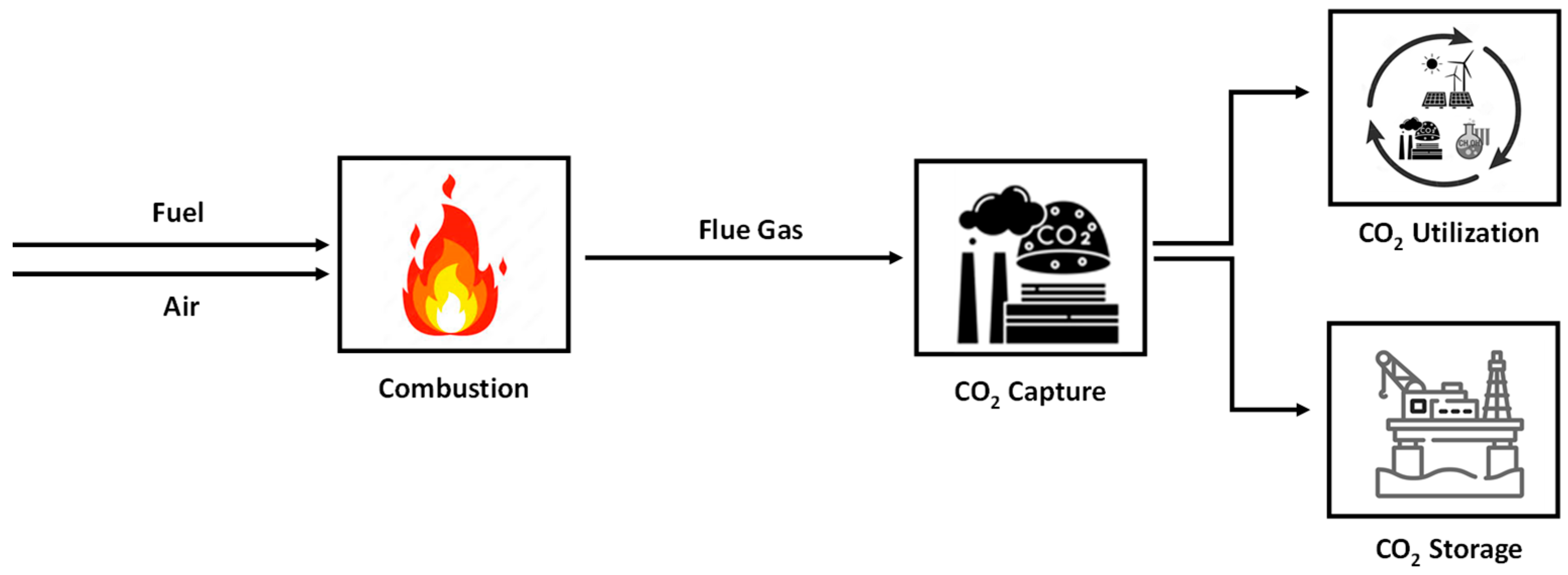
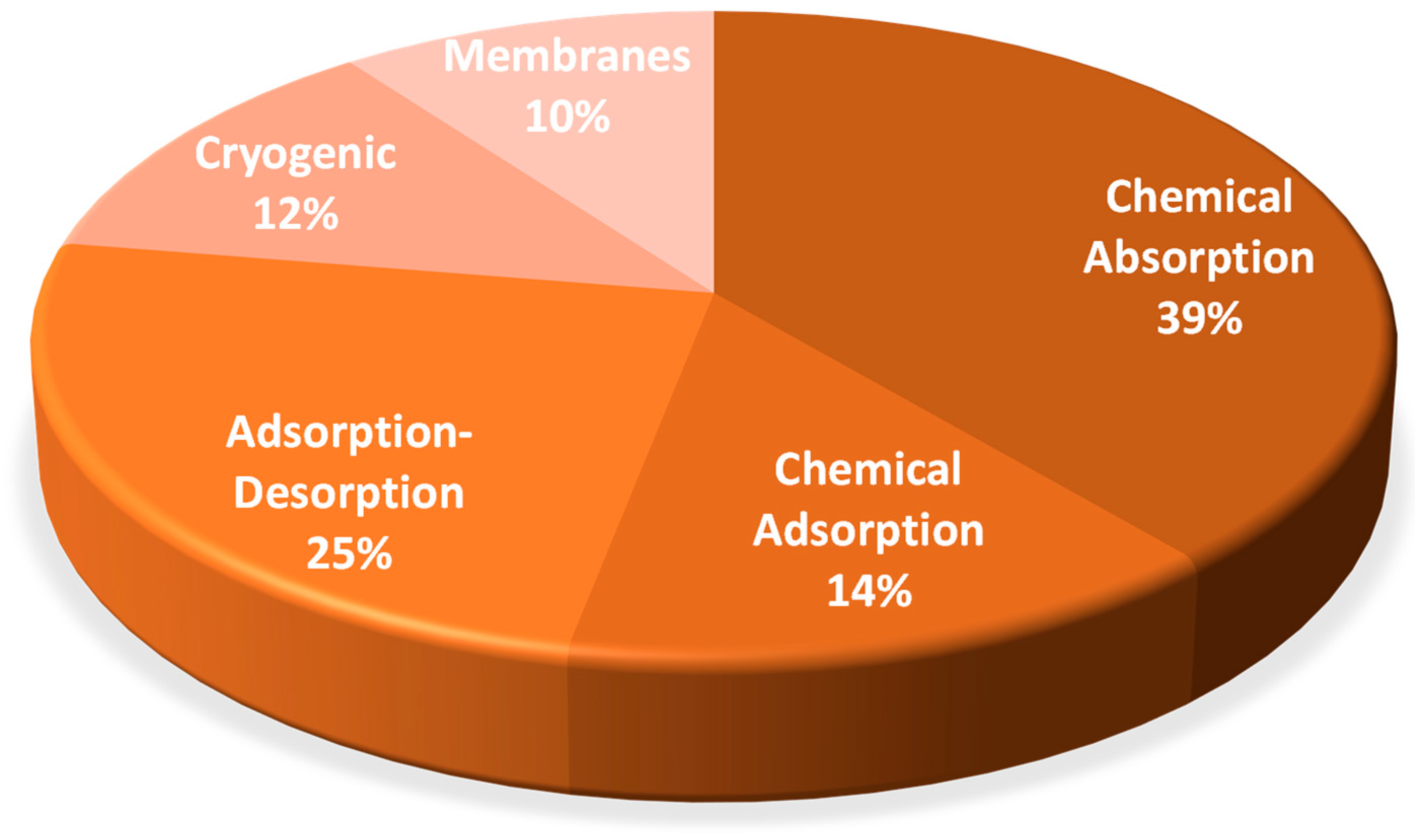
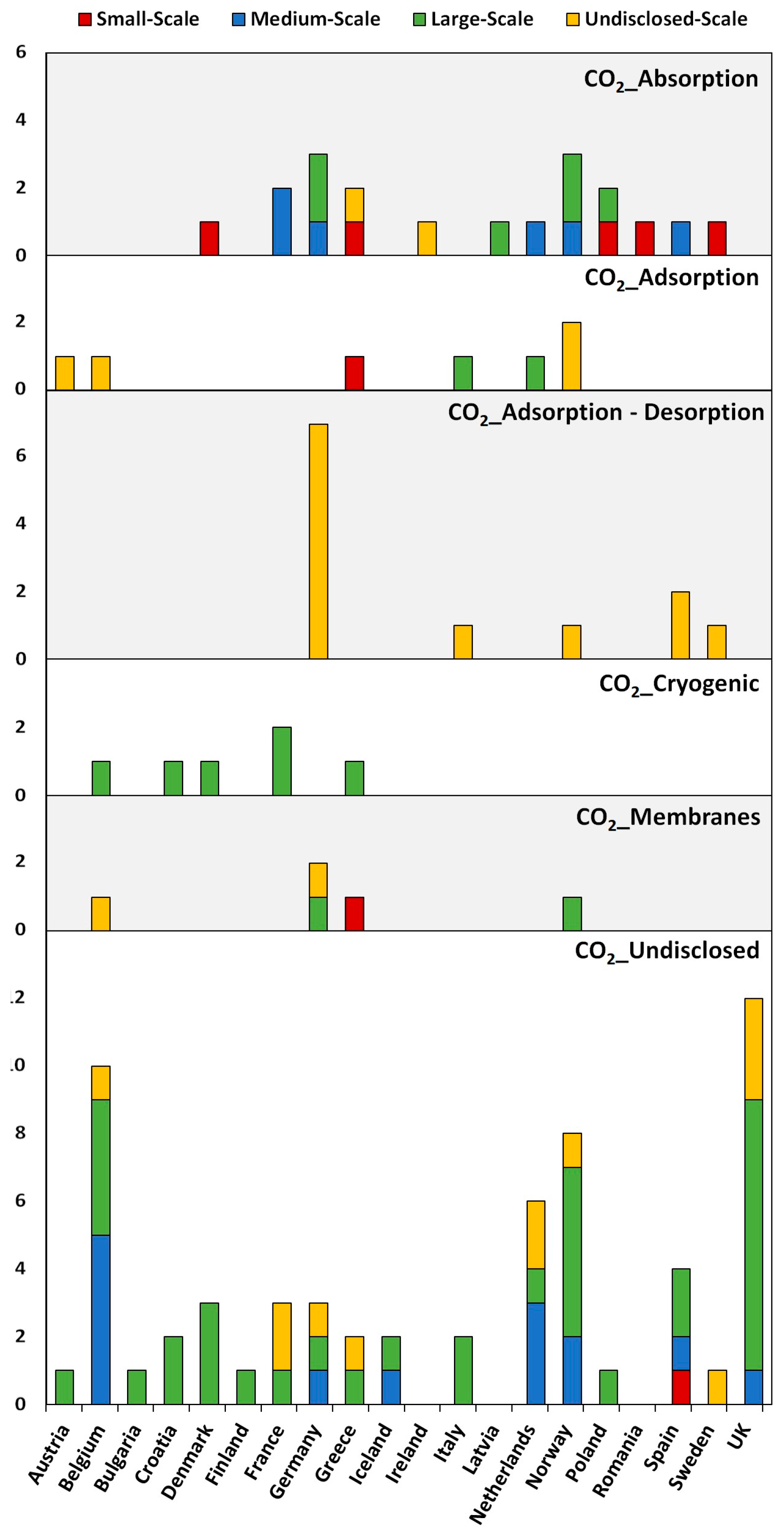

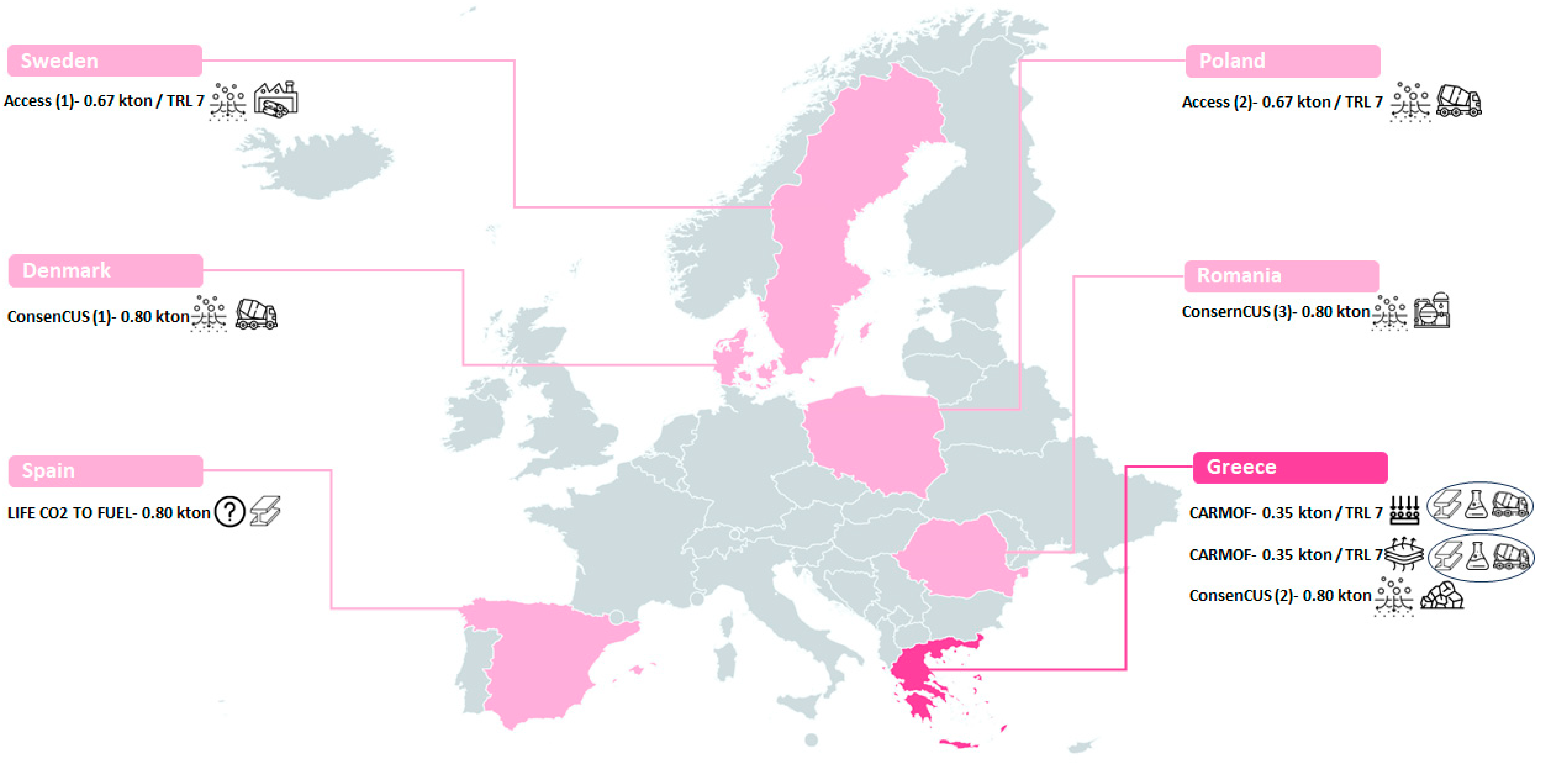

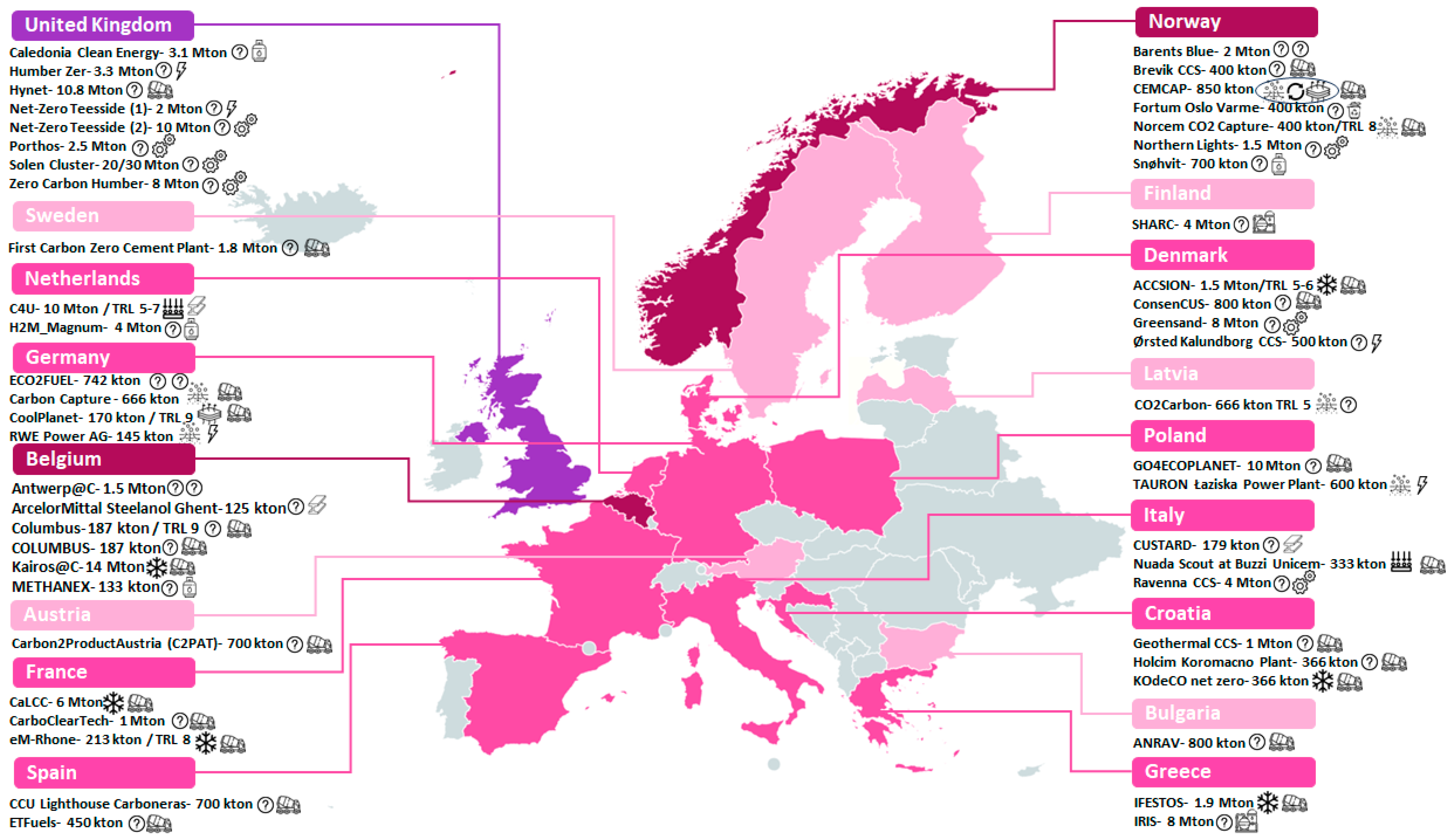

Disclaimer/Publisher’s Note: The statements, opinions and data contained in all publications are solely those of the individual author(s) and contributor(s) and not of MDPI and/or the editor(s). MDPI and/or the editor(s) disclaim responsibility for any injury to people or property resulting from any ideas, methods, instructions or products referred to in the content. |
© 2025 by the authors. Licensee MDPI, Basel, Switzerland. This article is an open access article distributed under the terms and conditions of the Creative Commons Attribution (CC BY) license (https://creativecommons.org/licenses/by/4.0/).