Abstract
The YZ-ZJ DC transmission project addresses significant power transmission challenges in a specific region’s power grid, which faces unique pressures due to overlapping “growth” and “transition” periods in energy demand. This study focuses on the integration of Controllable-Line-Commutated Converters (CLCCs) into the YZ-ZJ DC transmission project at the receiving end, replacing the traditional LCCs to mitigate commutation failures during AC system faults. The main innovation lies in the development of a hybrid electromechanical–electromagnetic simulation model based on actual engineering parameters that provides a comprehensive analysis of the CLCC’s electromagnetic characteristics and system-level behavior under fault conditions. This is a significant advancement over previous research, which mainly focused on discrete electromagnetic modeling in ideal or simplified scenarios without considering the full complexity of real-world regional power grids. The research demonstrates that integrating CLCCs into the regional power grid not only prevents commutation failures but also enhances the overall reliability of the transmission system. The results show that CLCCs significantly improve fault tolerance, stabilize power transmission during faults, reduce power fluctuations in neighboring transmission lines, and enhance grid stability. Furthermore, this study confirms that the CLCC-based YZ-ZJ DC project outperforms the traditional LCC system, maintaining stable power transmission even under fault conditions. In conclusion, this study validates the feasibility of CLCCs in resisting commutation failures when integrated into a large power grid and reveals their positive impact on the regional grid.
1. Introduction
The power grid in the studied region is undergoing concurrent “growth” and “transition” phases, resulting in considerable transmission pressure [1]. To alleviate grid congestion and improve energy flow from the resource-rich northern region (Jiangbei) to the high-load southern region (Jiangnan), the YZ-ZJ DC transmission project has been proposed. This project converts part of the existing AC infrastructure into a hybrid AC/DC system via an embedded DC transmission scheme.
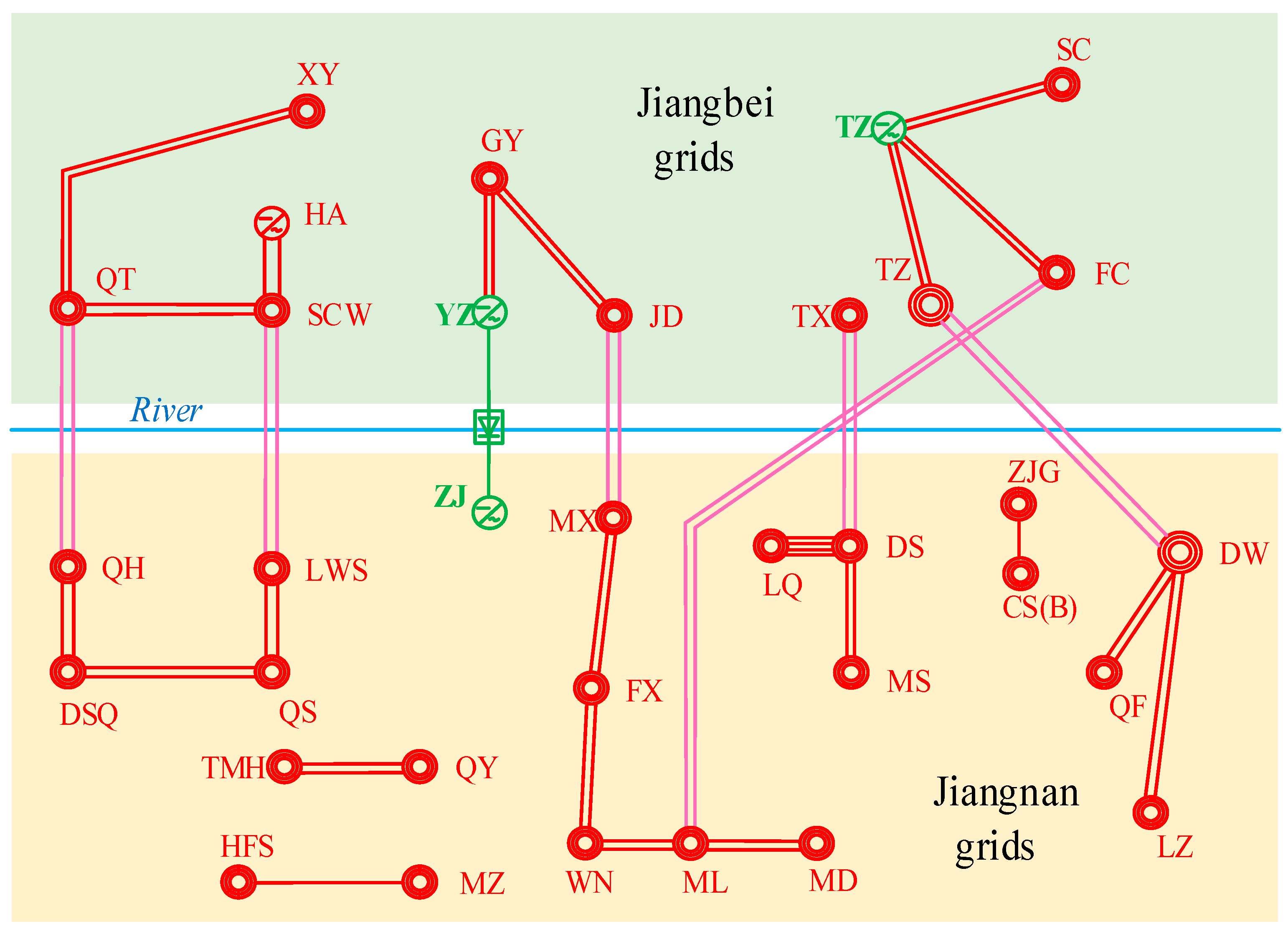
The cross-river section, a key power transmission route, is depicted in the schematic diagram of the region’s cross-river grid shown in Figure 1.

Figure 1.
Schematic diagram of the region’s cross-river section.
The red lines represent the direct current (DC) transmission lines between the respective converter stations in the Jiangnan and Jiangbei regions. The pink cross-river channels correspond to the existing transmission lines in the region, while the green cross-river channel represents the newly constructed YZ-ZJ DC project. The power flow discussed in this paper is directed from the Jiangbei region to the Jiangnan region, with the power flow being measured in the Jiangnan region.
The existing cross-river channel is composed of five main transmission sections: the west channel, which includes the QT-QH and SCW-LWS double-circuit lines; the central channel, which consists of the JD-MX double-circuit line; and the east channel, which consists of the TX-DS and FC-ML double-circuit lines. The UHV channel is formed by the 1000 kV TZ-SZ double-circuit line. The central channel, having only one AC transmission line, faces heavy transmission pressure, and the bottleneck issue is prominent.
DC transmission technology has provided a new approach to enhance the power transmission capacity of the cross-river section [2]. To make full use of the existing cross-river transmission resources, one of the existing double-circuit AC lines will be transformed into a three-circuit bipolar DC line. The use of AC-to-DC conversion technology can significantly increase the transmission capacity of the line, alleviating the overload issue of the central channel. As the sending and receiving ends are situated within the region’s AC grid and span across both sides of the river, the DC transmission system at each end is “embedded” within the AC grid, creating a hybrid AC-DC operational configuration. Therefore, this DC system is termed “embedded” DC.
The commissioning of the YZ-ZJ DC transmission line can enhance the overall transmission capacity of the AC-DC cross-river channels by approximately 800 MW during the winter peak periods and by about 1000 MW during the summer peak periods. Overall, the operation of the YZ-ZJ DC project can meet the renewable energy integration, absorption, and delivery needs in the 220 kV grid sections of renewable energy-rich areas such as YZ and TZ. It also improves the receiving capacity of the 220 kV grid in the Jiangnan region, which is characterized by high load density, and enhances the overall transmission capability of the north-to-south power transmission corridor in the region’s grid.
However, since the YZ-ZJ DC project still uses traditional LCCs (Line-Commutated Converters) [3,4] and this project is an “embedded” DC system, the rectifier and inverter sides are electrically close, leading to tight electrical coupling between the two ends. Not only will commutation failure [5,6,7,8,9] occur under faults in the receiving end’s AC grid, but if a short-circuit fault in the rectifier-side AC system causes voltage dips, commutation failure may occur on the inverter side, interrupting power transmission and failing to alleviate the transmission issue of the cross-river channel. Additionally, when commutation failure occurs in the YZ-ZJ DC system, the other cross-river channels may experience power limit violations, affecting the stable operation of the power grid.
In recent studies, advanced fault detection methods have been proposed for improving HVDC system stability. For example, reference [10] introduced an improved relay algorithm for detecting and classifying transmission line faults in monopolar HVDC systems. This method, using the Signum function of transient energy, has shown potential for enhancing fault management strategies and can be applied in HVDC projects such as the YZ-ZJ DC project to refine fault detection systems.
Current methods for addressing commutation failure can be classified into two main approaches: improving control strategies and improving the topology. Regarding control strategy improvements, reference [11] introduced rapid prediction and detection techniques for commutation failure using detection algorithms and mathematical models, allowing for the early triggering of thyristor valves and increasing the turn-off angle. However, this method can only reduce the probability of commutation failure to some extent. References [12,13,14] suggested using voltage-dependent current order limitation (VDCOL) control to limit DC current during AC system faults to reduce active and reactive power fluctuations and improve VDCOL control methods to suppress the risk of subsequent commutation failures. However, due to the characteristics of thyristor devices, existing control strategies cannot fully prevent commutation failure. A true solution to preventing commutation failure requires improvements in the topology.
References [15,16] propose a Capacitor Commutated Converter (CCC), which can help minimize the occurrence of commutation failure. However, when the system experiences severe AC faults, it is unable to effectively control the capacitor overvoltage, which may still lead to commutation failure. References [17,18] proposed the SLCC (SVG and Line-Commutated Converter) solution, where a large-capacity SVG with an active filtering function is directly connected in parallel at the AC side of the LCC. This solution uses a cascaded H-bridge structure to build a large-capacity SVG device, which is directly connected in parallel with the converter transformer’s valve side. It can simultaneously achieve reactive power control on the LCC AC side and harmonic current filtering while compensating for commutation current, significantly improving both AC system voltage stability and commutation failure suppression. However, this solution can only reduce the risk of commutation failure to some extent and cannot fully prevent commutation failure.
Building upon this, reference [19] introduced a novel topology known as the Controllable-Line-Commutated Converter (CLCC), which integrates Insulated Gate Bipolar Transistors (IGBTs) into the traditional LCC valve group. By incorporating fully controllable devices and introducing auxiliary branches capable of fault current transfer, the CLCC ensures the reliable turn-off of main branch thyristors and fundamentally eliminates the occurrence of commutation failure.
To validate the practical effectiveness of this topology, the present study applies the CLCC to the receiving end of the YZ-ZJ DC transmission project. An electromagnetic transient model is developed in ADPSS, coupled with an electromechanical transient model based on the actual topology and operating conditions of the regional power grid. A hybrid simulation framework combining both domains is constructed to comprehensively analyze the electrical behavior of the CLCC under AC fault conditions and assess its impact on system-level performance.
Specifically, the contributions of this study can be summarized as follows:
- Proposing the deployment of CLCCs at the receiving end of the YZ-ZJ DC project to eliminate commutation failures caused by AC system disturbances;
- Constructing a hybrid simulation model that combines electromagnetic and electromechanical transients for comparative performance evaluation between CLCCs and conventional LCCs;
- Analyzing the application of the CLCC in large-scale regional power grids by incorporating actual engineering parameters, providing insights into its behavior and impact on system performance under real-world conditions.
This study aims to fill a critical gap in the existing literature regarding the application of Controllable Line-Commutated Converters (CLCCs) in real-world regional power grids, particularly in their role in mitigating commutation failure and enhancing the fault tolerance of HVDC systems. Most of the existing research on CLCCs has primarily focused on discrete electromagnetic modeling and theoretical analysis, typically limited to ideal operating conditions or simplified system configurations. Such studies lack a comprehensive assessment of the CLCC’s engineering adaptability, its system-level dynamic behavior, and its impact on the stability of surrounding AC networks within complex regional grid environments.
To bridge this gap, this study builds a hybrid electromechanical–electromagnetic simulation model in ADPSS, based on actual engineering parameters and the topology of the regional power grid. By embedding the CLCC into the actual receiving-end AC network and analyzing its performance under fault conditions, this study provides a comprehensive system-level assessment. The results offer both theoretical insights and empirical evidence to support the practical deployment of CLCC technology in modern HVDC applications.
The remainder of this paper is organized as follows:
Section 2: Overview of the YZ-ZJ DC transmission project, its converter topology, and the proposed CLCC solution.
Section 3: Details on the control strategies and operating modes for CLCCs.
Section 4: Simulation setup, results, and analysis of the CLCC’s performance.
Section 5: Discussion of the results.
Section 6: Conclusion and suggestions for future research and improvements.
2. YZ-ZJ DC Transmission Project Converters and CLCCs
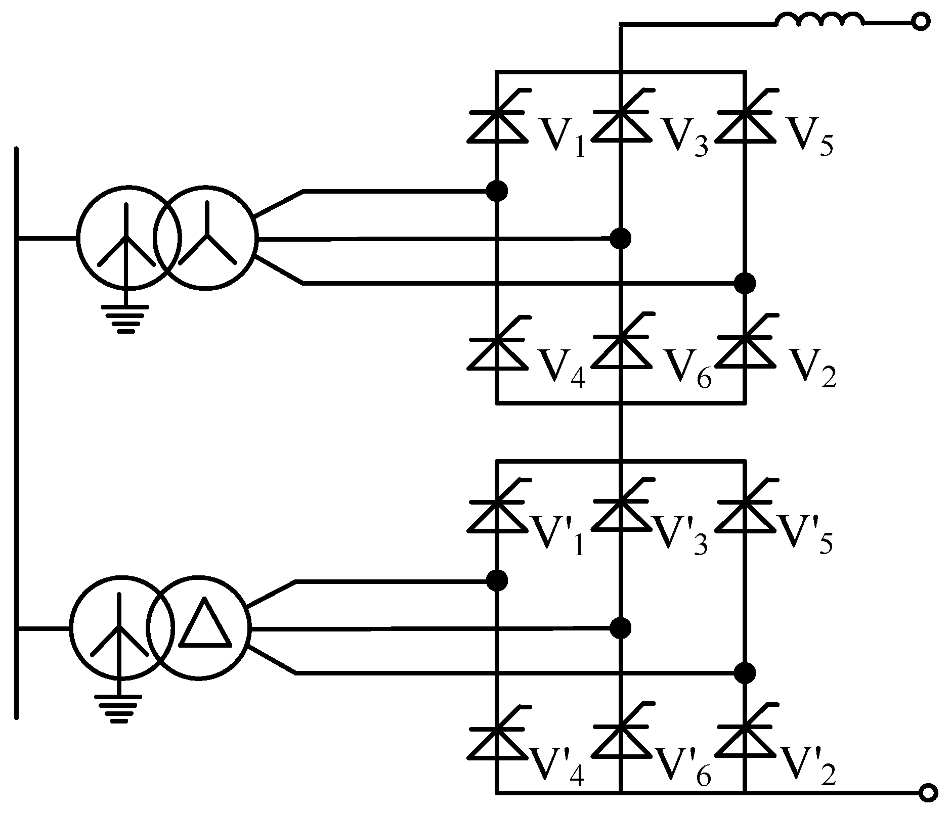
The YZ-ZJ DC project employs conventional 12-pulse LCCs (Line-Commutated Converters) at both ends. Figure 2 illustrates the converter’s basic configuration, where two six-pulse converters are connected in series on the DC side, while on the AC side, they are linked to the AC system in parallel via a converter transformer.

Figure 2.
Topology of the 12-pulse LCC valve.
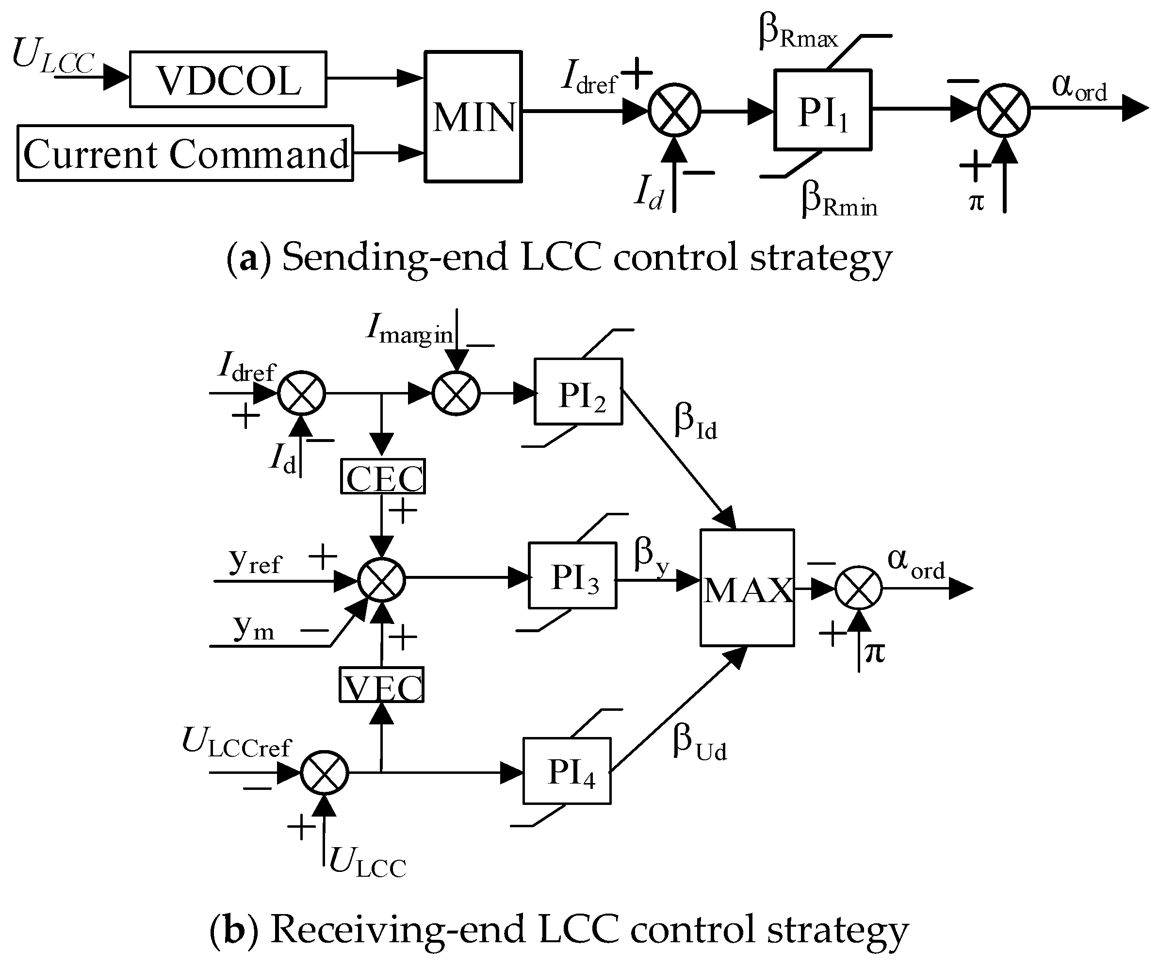
In this project, the control strategy of the LCC converter is shown in Figure 3. The sending-end LCC employs constant DC current control, with additional minimum triggering angle control and voltage-dependent current order limit (VDCOL) control. The receiving-end LCC uses constant DC voltage control, along with constant extinction angle control and constant current control [20,21]. Similar to the sending-end LCC, it also includes minimum triggering angle control and VDCOL control. Additionally, to prevent frequent switching between control modes, current error control (CEC) and voltage error control (VEC) are implemented. The VEC loop takes the deviation between the set and actual DC voltage of the receiving-end LCC as an input, and the output is added to the constant extinction angle control, allowing the LCC’s DC voltage to quickly decrease to the set value.

Figure 3.
YZ-ZJ DC project’s LCC station control strategy.
The topology of the Controllable-Line-Commutated Converter (CLCC), being unlike that of the LCC used in the YZ-ZJ DC project, is shown in Figure 4. This converter can be directly modified from the existing LCC topology, offering strong engineering adaptability.

Figure 4.
CLCC topology.
In this topology, each bridge arm of the six-pulse converter is made up of a main and an auxiliary branch connected in parallel, with both branches consisting of a thyristor valve and an IGBT valve in series.
Taking valve 4 as an example, the thyristor valve V41 and the fully controllable IGBT valve V42 form the main branch, which conducts under normal operation. A second set of thyristor valve V43 and IGBT valve V44 is connected in parallel with the main branch to form the auxiliary branch. During commutation, the IGBT valve in the main branch turns off actively, transferring the current to the auxiliary branch. The auxiliary branch temporarily carries the transferred current and, after a brief delay, switches off, ensuring the bridge arm completes the commutation process and shuts off reliably.
3. CLCC Control Strategy and Operating Mode
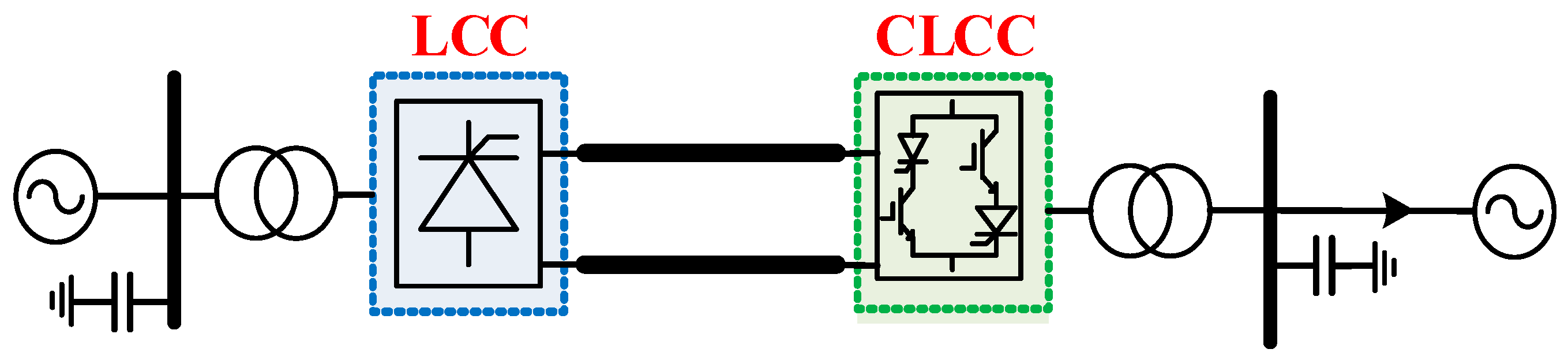
The LCC at the receiving end of the YZ-ZJ DC project is modified to a CLCC based on the existing infrastructure. The schematic diagram of the DC transmission project after the modification is shown in Figure 5.
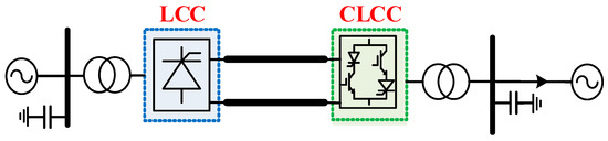
Figure 5.
YZ-ZJ DC project after the receiving-end converter station is modified to CLCC.
When the LCC valves at the receiving end of the YZ-ZJ DC project are replaced by the new Controllable-Line-Commutated Converters (CLCCs), there is no need to equip the CLCCs with commutation failure prediction controls [22,23,24], as they do not face the issue of commutation failure. Furthermore, their control logic is compatible with existing control strategies. The switching signals for the switches are triggered based on the current conduction signal of the main branch thyristor in each valve, and the triggering logic is illustrated in Figure 6, where Sg11 and Sg12 correspond to the switching signals for the main branch thyristor and IGBT, while Sg13 and Sg14 represent the switching signals for the auxiliary branch thyristor and IGBT.
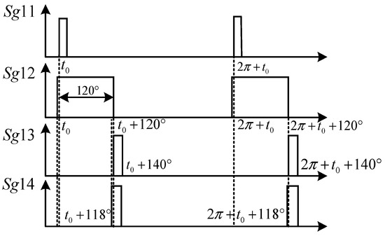
Figure 6.
Triggering logic of the CLCC.
Under normal operating conditions, the characteristics of the CLCC are consistent with those of the LCC. However, during AC faults in the receiving end system, the CLCC operates in fault operating mode. After the main branch is turned off, the fault current is transferred to the auxiliary branch and energy is dissipated through the auxiliary branch’s surge arresters, thereby suppressing overcurrent conditions during fault states.
3.1. Normal Operation Mode
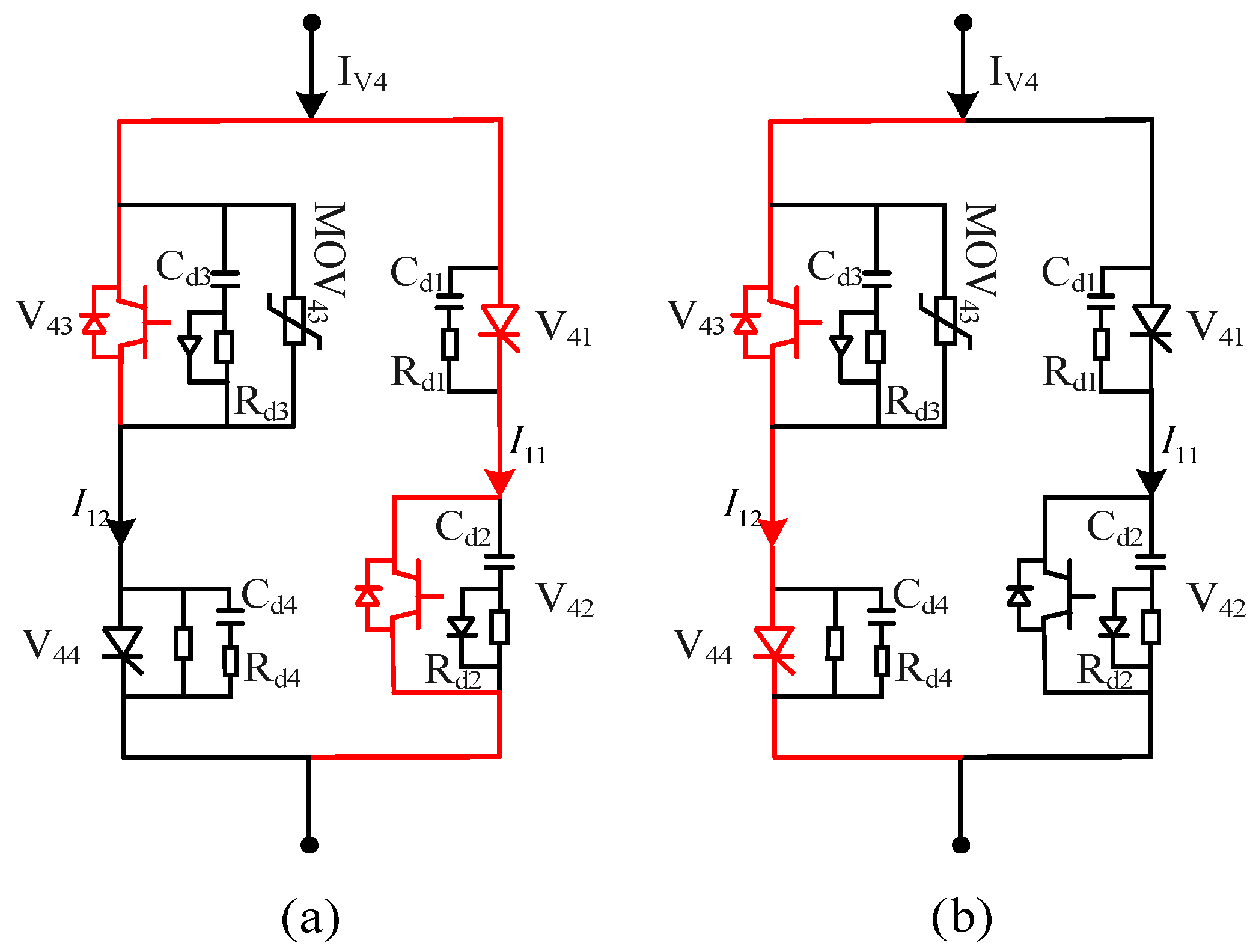
During normal operation of the CLCC, its electrical characteristics are identical to those of a traditional LCC. When the triggering signal is received by the corresponding bridge arm, the main branch is activated, allowing current to flow through it, as illustrated in Figure 7a. After natural commutation, the main branch IGBT V42 is deactivated and the auxiliary branch IGBT V44 is activated, redirecting the current to the auxiliary branch, as shown in Figure 7b. At this point, due to the presence of line and device parasitic inductance in the main branch, the residual current in the main branch charges the capacitor Cd2. The reverse voltage across the thyristor is considered to be the voltage across Cd2 and the reverse recovery charge effect, which accelerates the recovery of the main branch thyristor, ensuring its reliable turn-off.
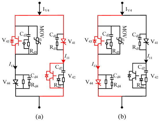
Figure 7.
Current path of the CLCC valve under normal operating mode. (a) Main branch conduction phase; (b) Auxiliary branch conduction phase.
3.2. Fault Operating Mode
For CLCCs, the control strategy under fault conditions is the same as during normal operation. The main reason CLCCs can withstand commutation failure is that the auxiliary branch can transfer the fault current under fault conditions, thereby ensuring that the main branch thyristor has sufficient time to recover its forward blocking capability.
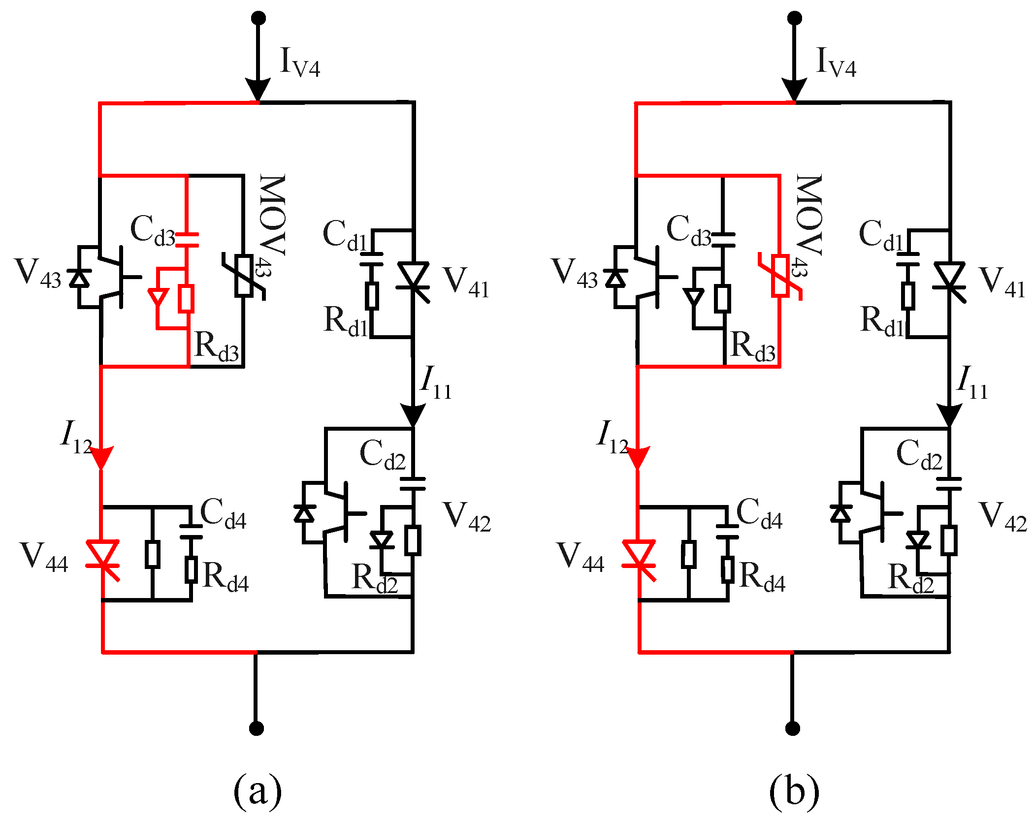
The auxiliary branch operates with the same logic for both normal and fault conditions. Unlike the normal operating mode, in the case of a fault, the auxiliary branch transfers the fault current from the main branch before it is switched off. When the IGBT V43 in the auxiliary branch actively turns off, the larger fault current is transferred to the capacitor Cd3 in parallel with the IGBT and charges it, as shown in Figure 8a. When the voltage built across the capacitor reaches the triggering voltage of the surge arrester MOV43, the arrester is triggered, and the fault current is transferred to the arrester, establishing a forward voltage across the arrester. This compensates for the voltage drop caused by the AC system fault, thereby ensuring the completion of the commutation process.

Figure 8.
Current path of the CLCC valve under fault operating mode. (a) Auxiliary branch turn-off current path; (b) Current path during arrester conduction.
The current path at this point is as shown in Figure 8b. During the process of transferring current to the auxiliary branch, the main branch thyristor has sufficient time to recover its forward blocking capability, thus enabling it to withstand the commutation failure fault.
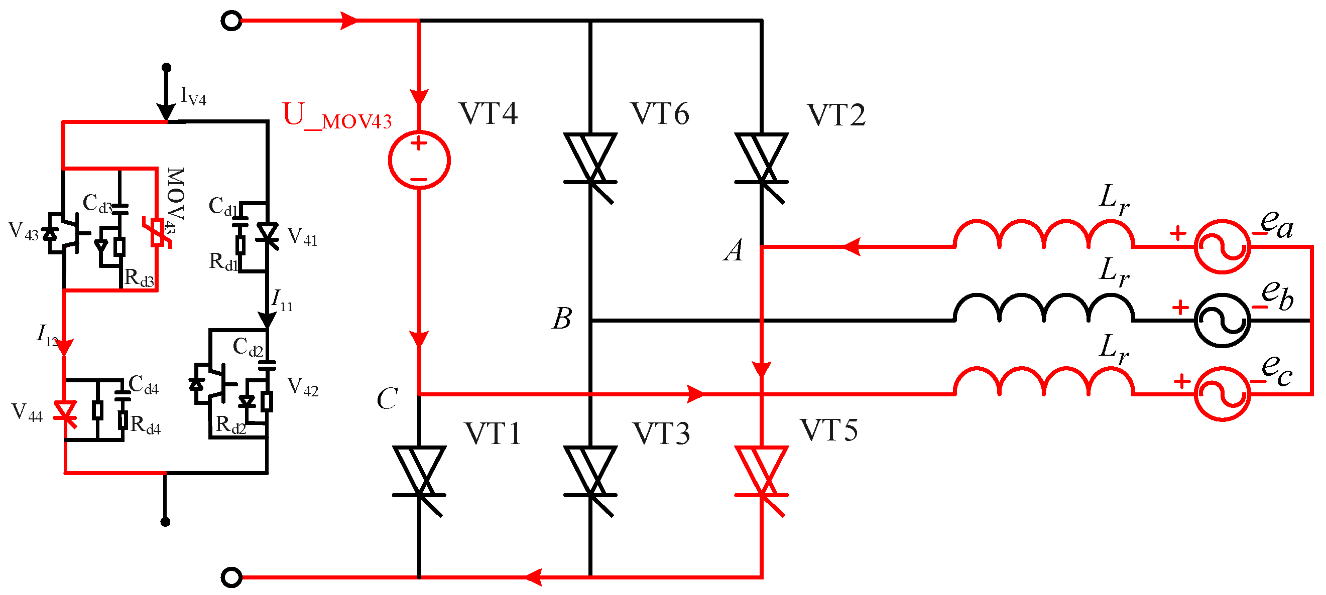
Under fault conditions, taking valve 4 as an example, the equivalent circuit at the moment of the turn-off of the auxiliary branch is shown in Figure 9. After the V43 IGBT turns off, the fault current rapidly charges the damping capacitor in the RC branch until the surge arrester is triggered. The U/I characteristics of the surge arrester ensure that when the DC current changes significantly, the voltage across the arrester remains approximately constant at U_MOV43. The commutation voltage is superimposed on the AC line voltage, adding the commutation voltage of the surge arrester, which further facilitates commutation. Using the parameters of the surge arrester already deployed in the Ge Nan project as a reference, by adjusting relevant parameters of the surge arrester, the energy dissipation power of a single valve surge arrester can fluctuate between 0–65 MW during faults. For the YZ-ZJ DC project, with 12 single valves in the bipolar configuration, the energy dissipation power provided by the surge arresters can fluctuate between 0–780 MW. Considering that the duration of a grounding fault generally does not exceed 100 ms, the energy margin of the valve surge arrester is sufficient to meet the energy dissipation requirements for grounding faults.
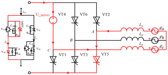
Figure 9.
Equivalent circuit at the moment of turn-off of the auxiliary branch of valve 4 under fault conditions.
By modifying the receiving-end converter station of the YZ-ZJ DC project to CLCCs, its electrical characteristics under normal operating conditions remain almost identical to those before the modification. However, under AC system faults at the receiving end, the modified system can withstand commutation failures, maintaining a certain level of power transmission during faults. This capability prevents the increased operational burden on other cross-river transmission channels due to faults at the receiving end.
4. Simulation
In the simulations of this paper, the AC power grid includes both the local grid and the neighboring provinces’ power systems, modeled for electromechanical transients using the Power System Analysis Software Package (PSASP). The model consists of generators, DC projects, transformers at voltage levels of 220 kV and above, transmission lines, etc., which are consistent with the actual project. The network below 220 kV is represented as a load model. In ADPSS, electromagnetic transient models based on LCCs and CLCCs have been established for the Yangzhen DC project, including the AC system interface, DC lines, converters at both ends, converter transformers, AC-DC filtering devices, and so on. The converter buses at both ends of the converter stations are connected to the AC system through electromechanical interfaces, and the impact on the regional power grid after replacing the receiving-end converter station of the Yangzhen DC project with a CLCC station is analyzed through electromechanical–electromagnetic hybrid simulation. After replacing the receiving-end converter station of the YZ-ZJ DC project with a CLCC station, the operating conditions of the project are considered under the 800 MW load during the winter peak period.
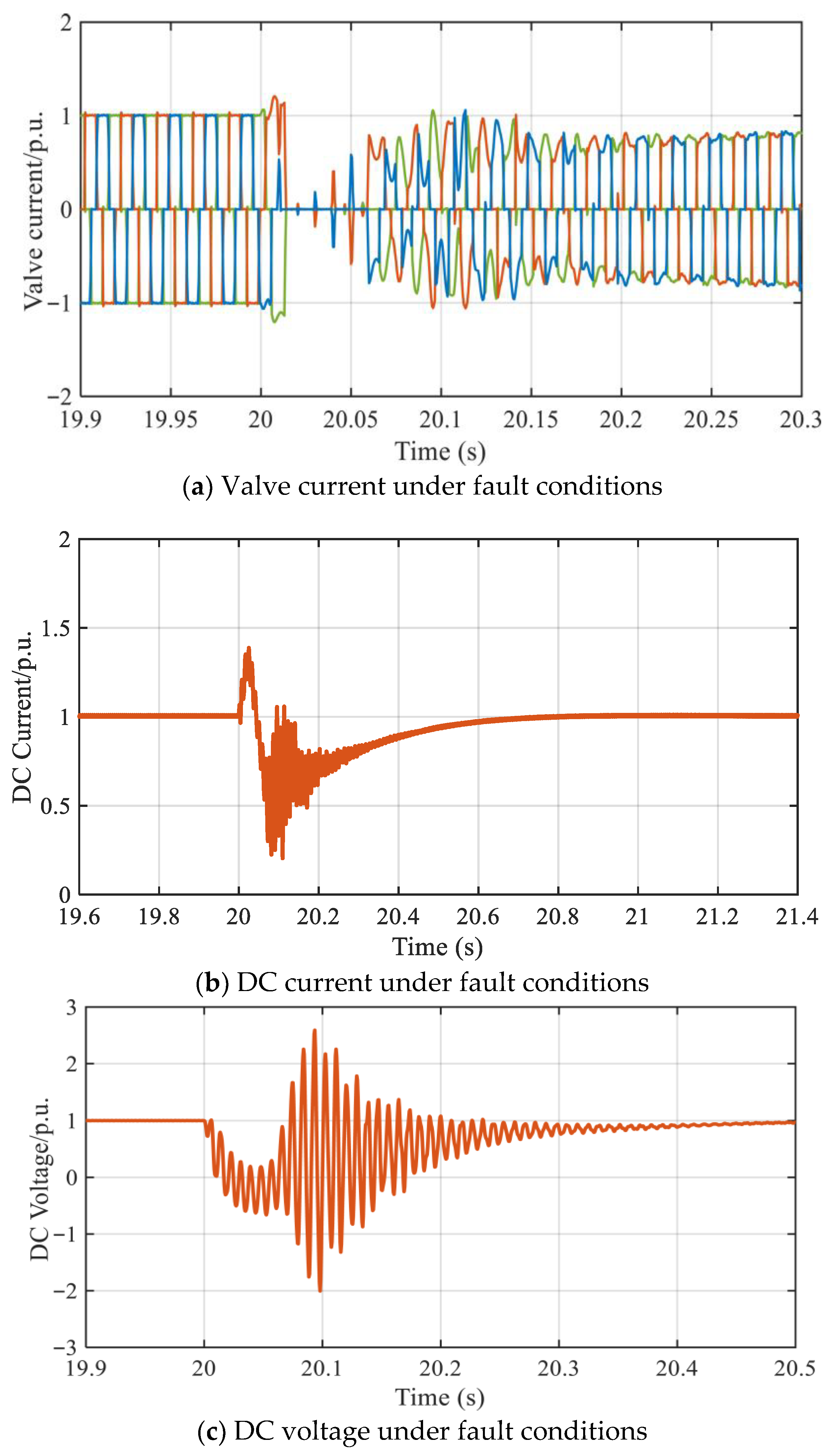
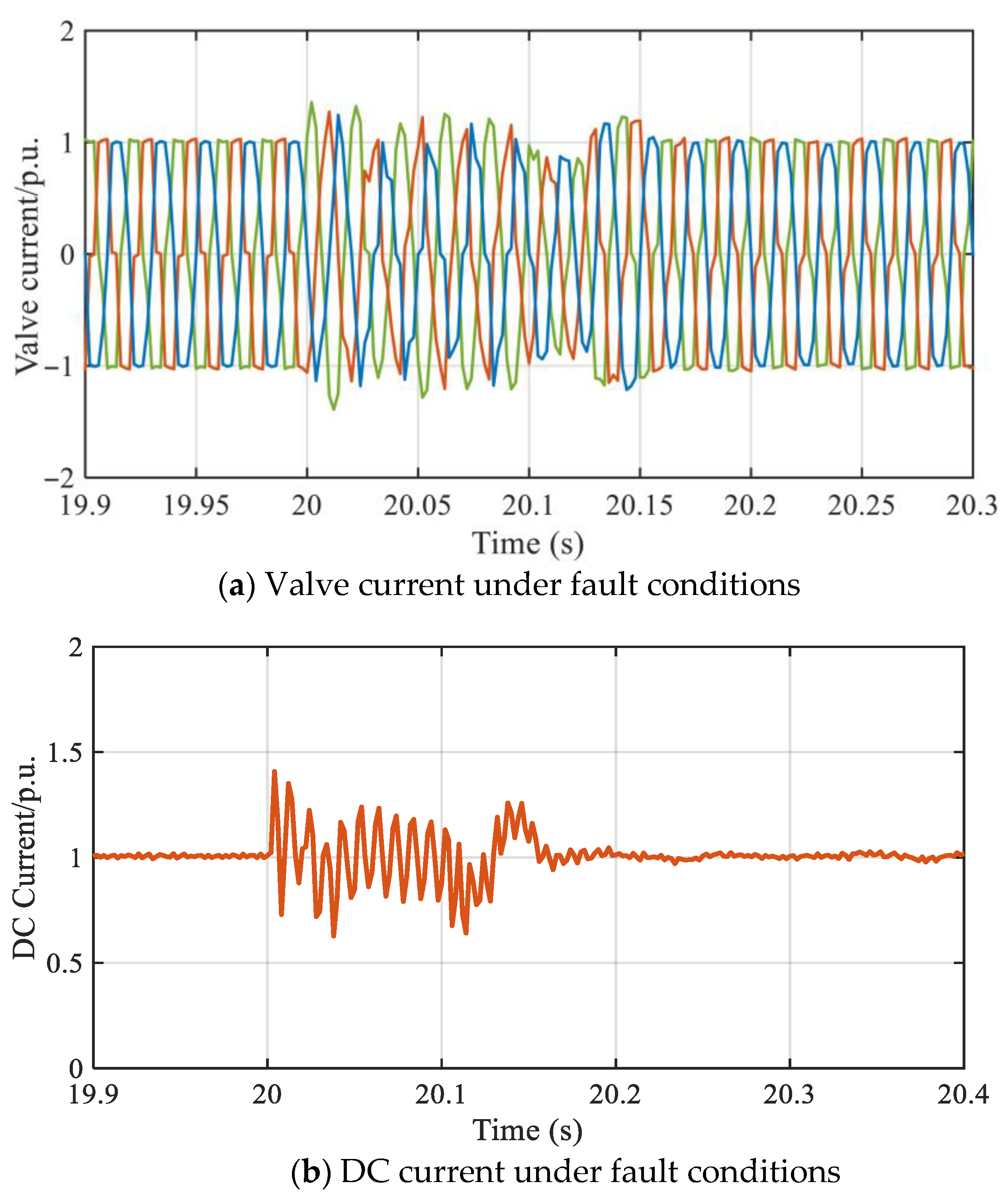
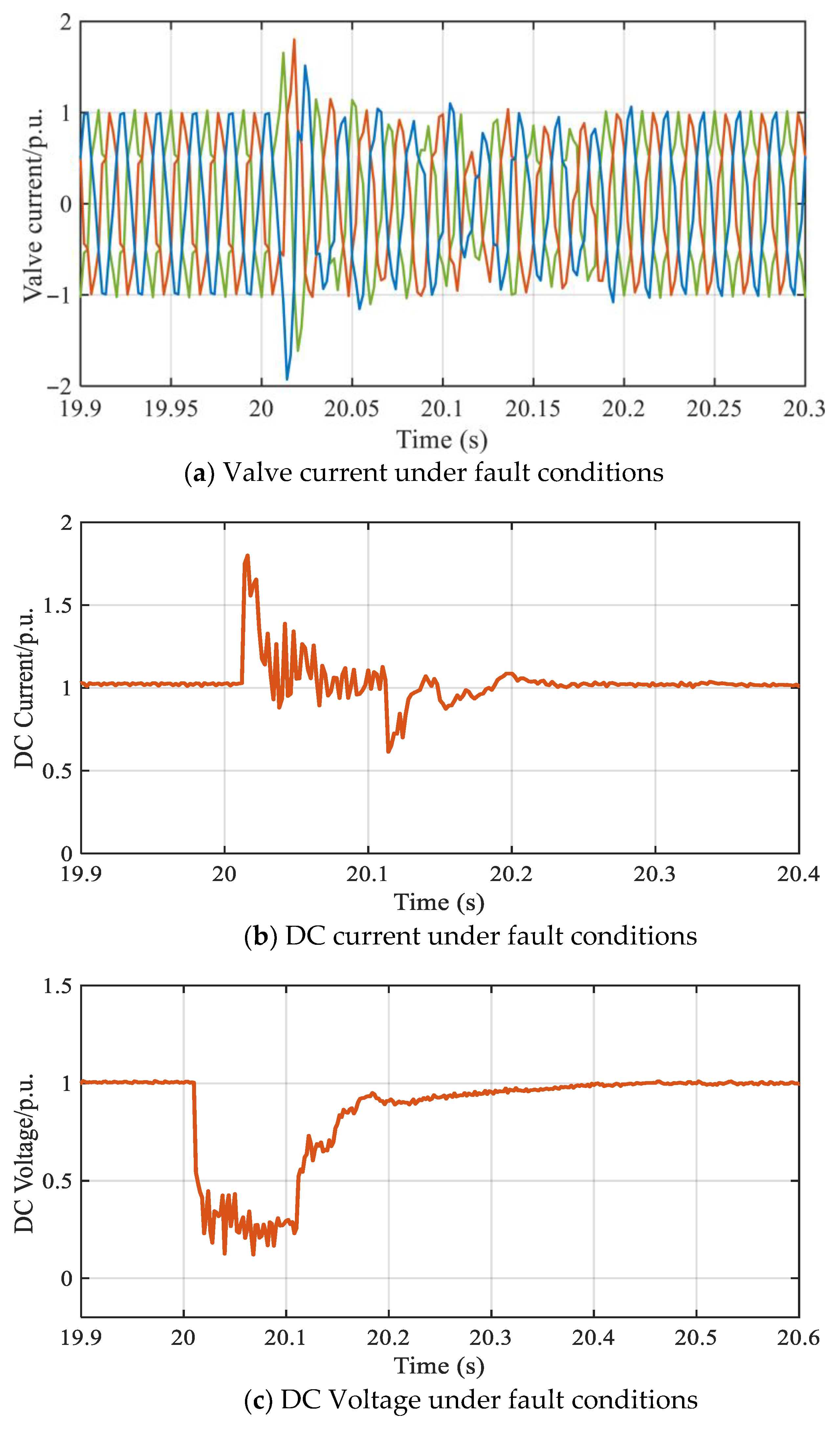
At 20 s, a single-phase ground fault is applied to the receiving-end AC power grid with a fault duration of 0.1 s. During this time, due to the voltage drop in the receiving-end AC grid, the LCC station experiences a commutation failure, causing its valve current to drop to zero. The DC current undergoes significant fluctuations and recovers to a stable value after approximately 0.7 s. Additionally, when the commutation failure occurs, the DC voltage drops below zero and experiences severe oscillations, which stabilize after about 0.5 s, as shown in Figure 10.
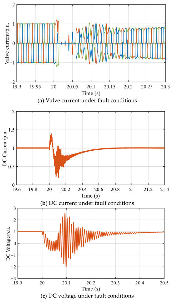
Figure 10.
Electrical characteristics of the original YZ-ZJ DC project under AC faults.
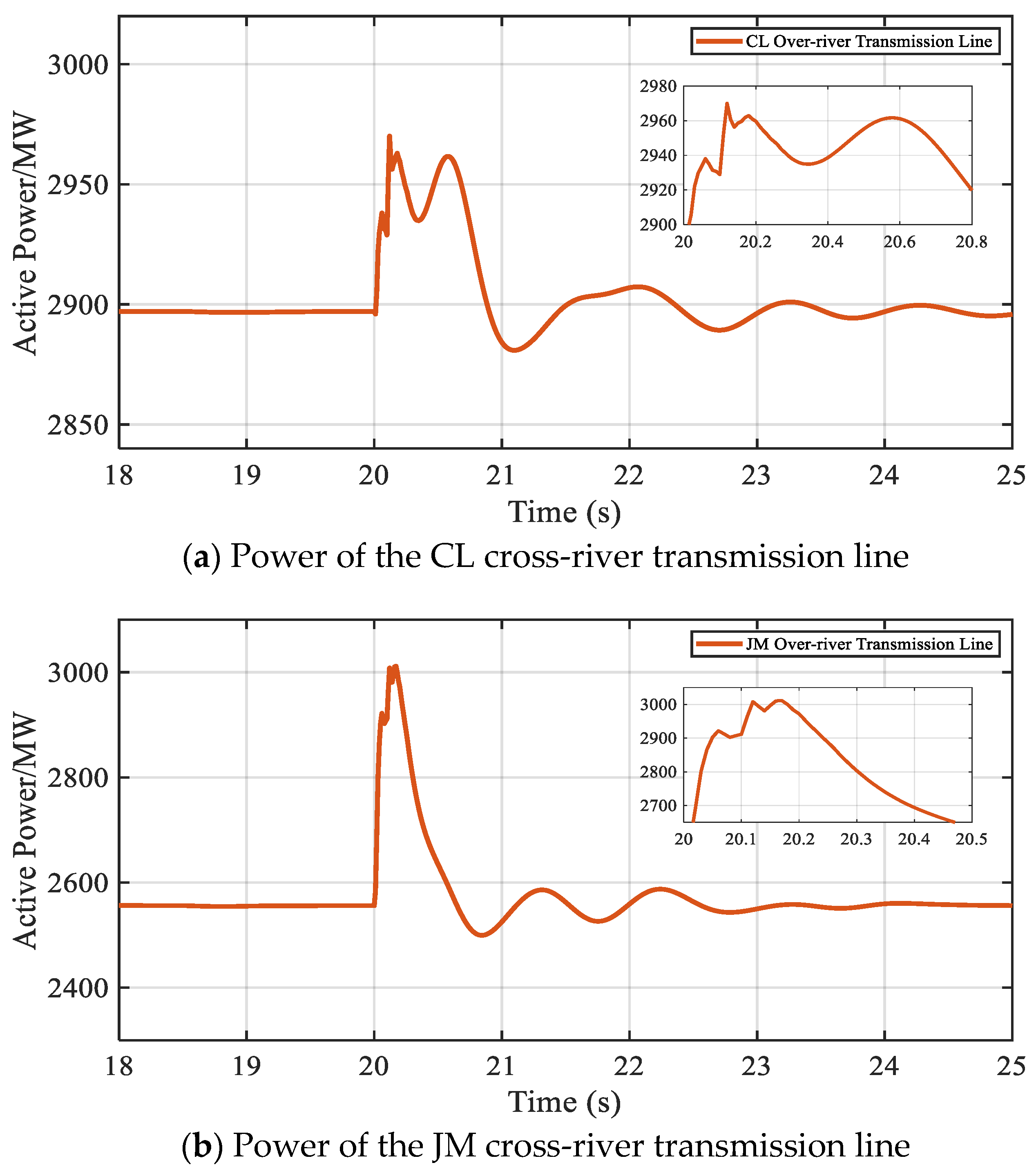
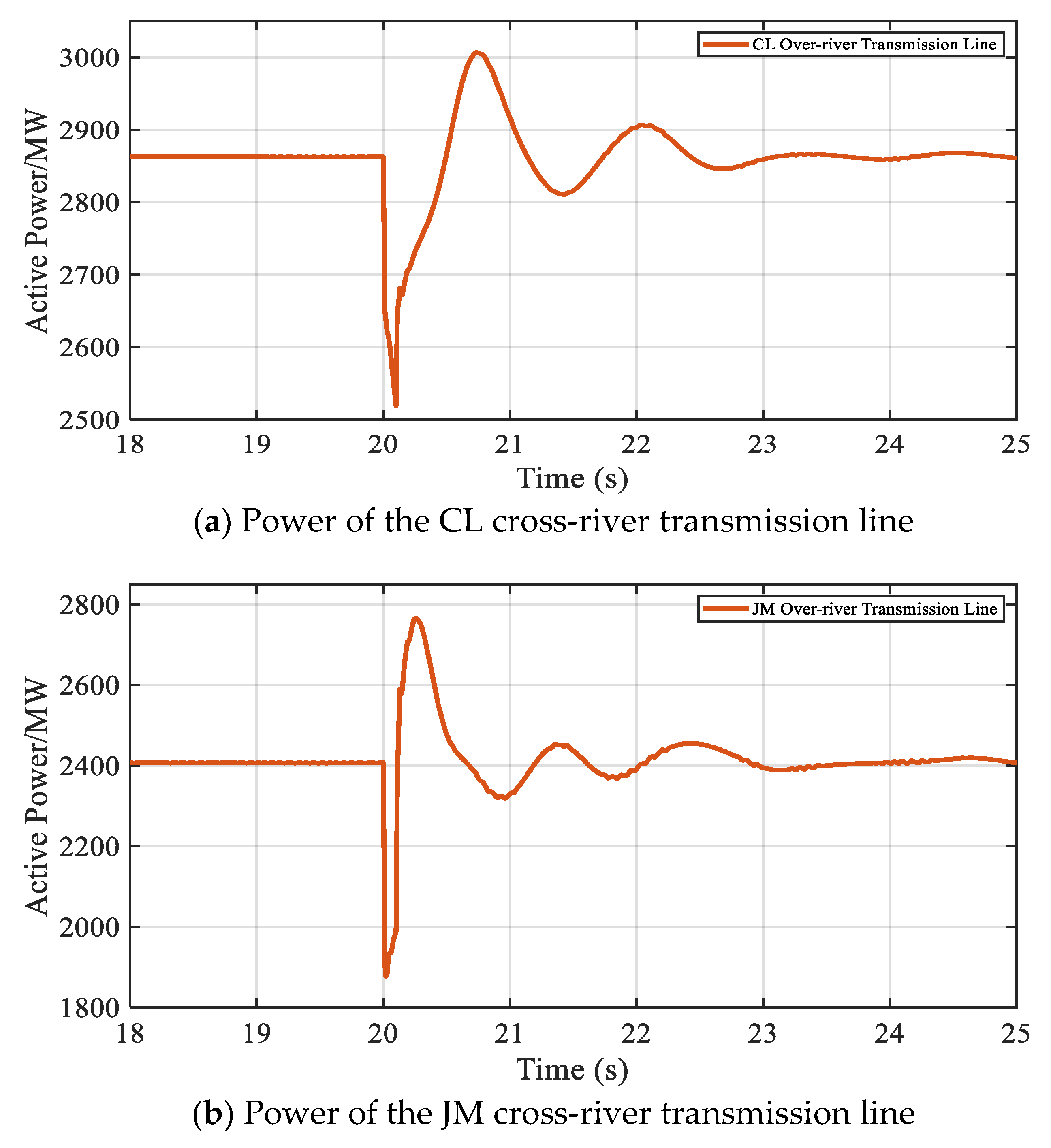
The power transmitted at this point through the JD-MX transmission line (referred to as JM) and the SCW-LWS transmission line (referred to as CL), which are strongly correlated with the YZ-ZJ DC project, is shown in Figure 11. Due to the commutation failure in the YZ-ZJ transmission line, it no longer has the capability to transmit power. Consequently, the power within the regional power grid is allocated to the JM and CL transmission channels, which are electrically closer, causing their transmitted power to increase dramatically.

Figure 11.
Power of the nearby cross-river transmission channels of the original YZ-ZJ DC project under AC system fault conditions.
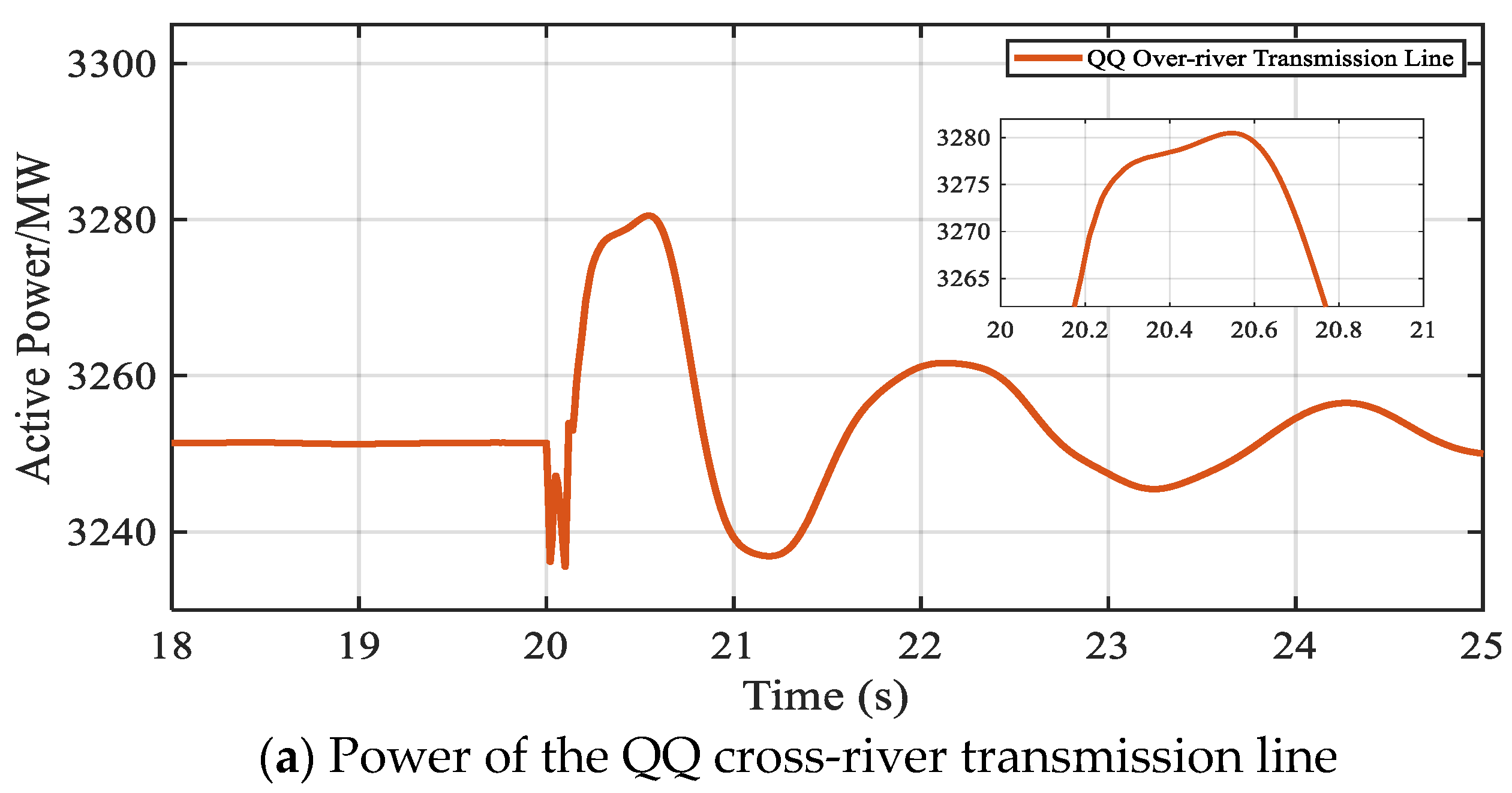
In addition, the QT-QH transmission line (referred to as QQ) and the TX-DS transmission line (referred to as TD), which are slightly farther from the YZ-ZJ DC project, also experience some degree of power fluctuations, as shown in Figure 12. Particularly for the TD transmission line, which has a smaller transmission capacity, the power increased by approximately 35% under the fault condition, raising the transmission pressure on the line and affecting the safe and stable operation of the regional power grid.

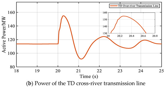
Figure 12.
Power of the distant cross-river transmission channels of the original YZ-ZJ DC project under AC system fault conditions.
However, for the CLCC, commutation failure can be resisted by operating in forced commutation mode. In this mode, the CLCC valve current remains continuous and the DC voltage and current experience small fluctuations. Moreover, it can recover to the steady-state value within 0.2 s after the fault occurs, demonstrating a stronger dynamic response capability compared to the LCC. This avoids prolonged current and voltage fluctuations, helping to reduce damage to electrical equipment. The waveforms of the CLCC at this time are shown in Figure 13.


Figure 13.
Electrical characteristics of the YZ-ZJ DC project with CLCCs at the receiving end under AC system fault conditions.
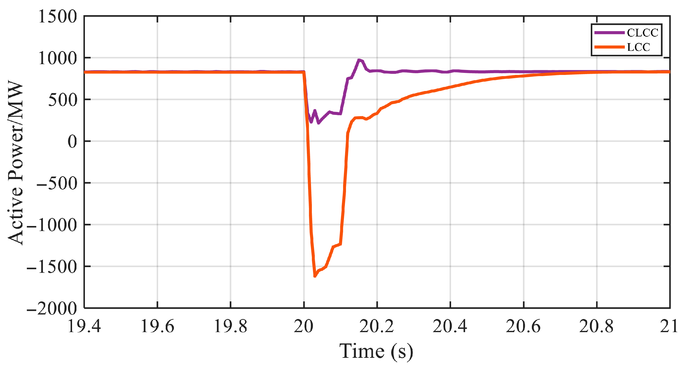
In the LCC-HVDC system, the converter relies on the receiving-end AC voltage for commutation, which means controlling the conduction and turn-off of the thyristors through natural commutation, enabling the transfer of DC power to the AC side. When a fault occurs in the receiving-end AC system, the AC voltage decreases, causing the thyristor to lose the required voltage for commutation. In this case, the thyristor, which should have been turned off, continues conducting and the new thyristor cannot be triggered, leading to commutation failure. The most severe consequence of commutation failure is that the receiving-end converter is unable to commutate properly, becoming an almost short-circuited voltage source connected to the system. The power, which should have been sent from the DC side to the AC system, is instead absorbed by the receiving end and fed back to the sending end due to control failure, resulting in the phenomenon of power reversal. Although the direction of the DC current remains unchanged, the polarity of the voltage changes, making the power P = V × I negative, leading to power reversal. The power transmitted by the receiving-end LCC station at this time is shown in Figure 14. Since the receiving-end CLCC station does not experience commutation failure, comparing the power transmitted by the YZ-ZJ DC project when using LCCs, it is evident that the YZ-ZJ DC project with CLCCs at the receiving end is still able to maintain a certain level of power transmission capability. By utilizing the forced commutation feature of the CLCC station, the system can avoid the negative effects of commutation failure, ensuring continuous power transmission and allowing the DC voltage and current to quickly return to steady-state values after a fault occurs.
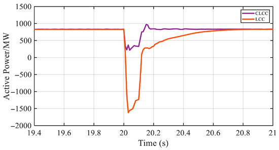
Figure 14.
Transmission power of the YZ-ZJ DC project with two types of converters at the receiving end under single-phase to ground fault conditions.
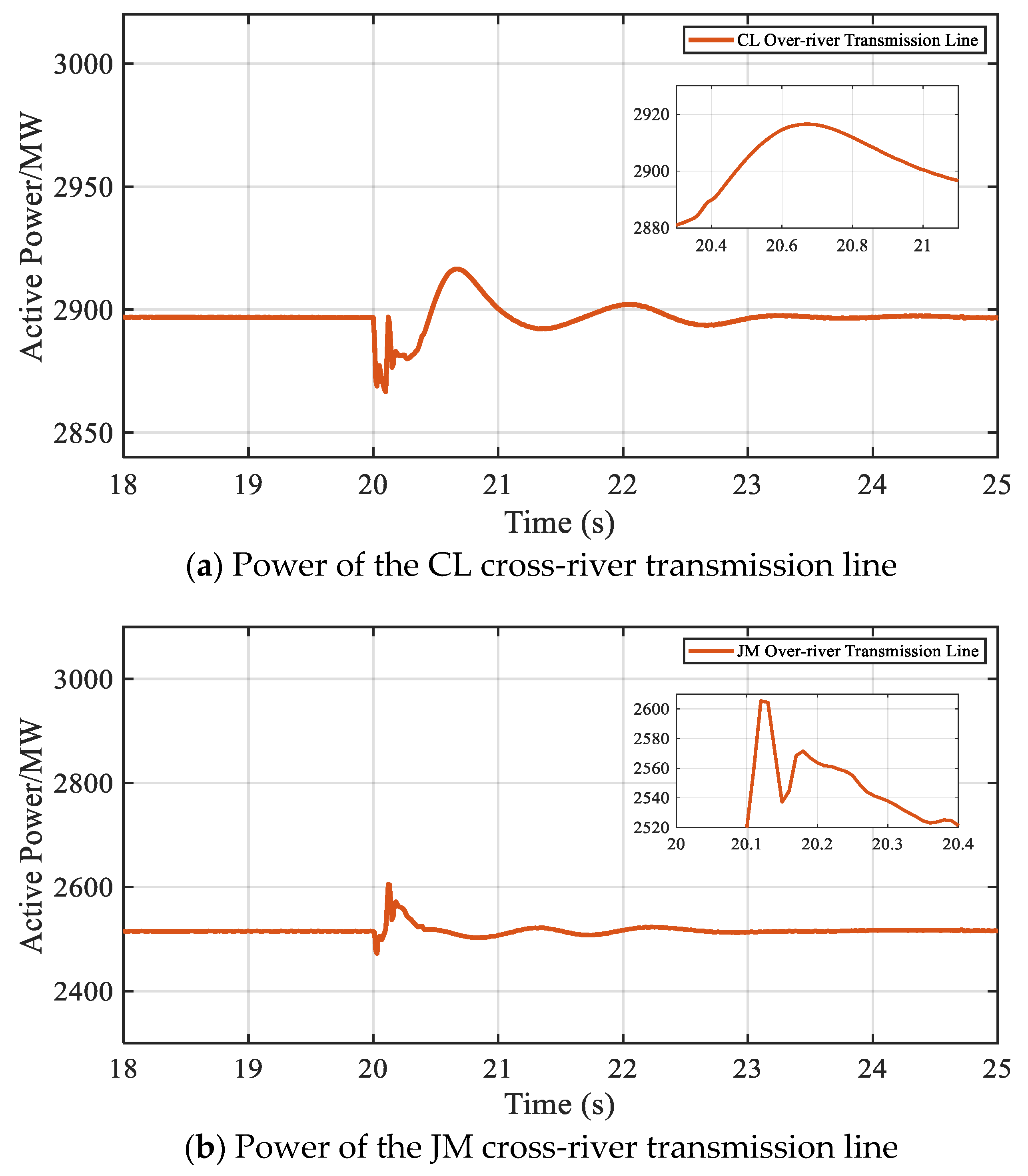
The power transmitted through the CL transmission line and the JM transmission line at this point is shown in Figure 15. After the fault occurs, the receiving-end CLCC station operates stably in forced commutation mode, preventing power interruptions caused by commutation failure. Compared to when using LCCs, CLCCs are more effective in maintaining the stability of power transmission. In this way, the power transmission in the CL and JM transmission lines becomes smoother, significantly enhancing the overall stability of the grid.

Figure 15.
Power of the nearby cross-river transmission channels of the YZ-ZJ DC project under AC fault conditions after replacing the receiving-end converters with CLCCs.
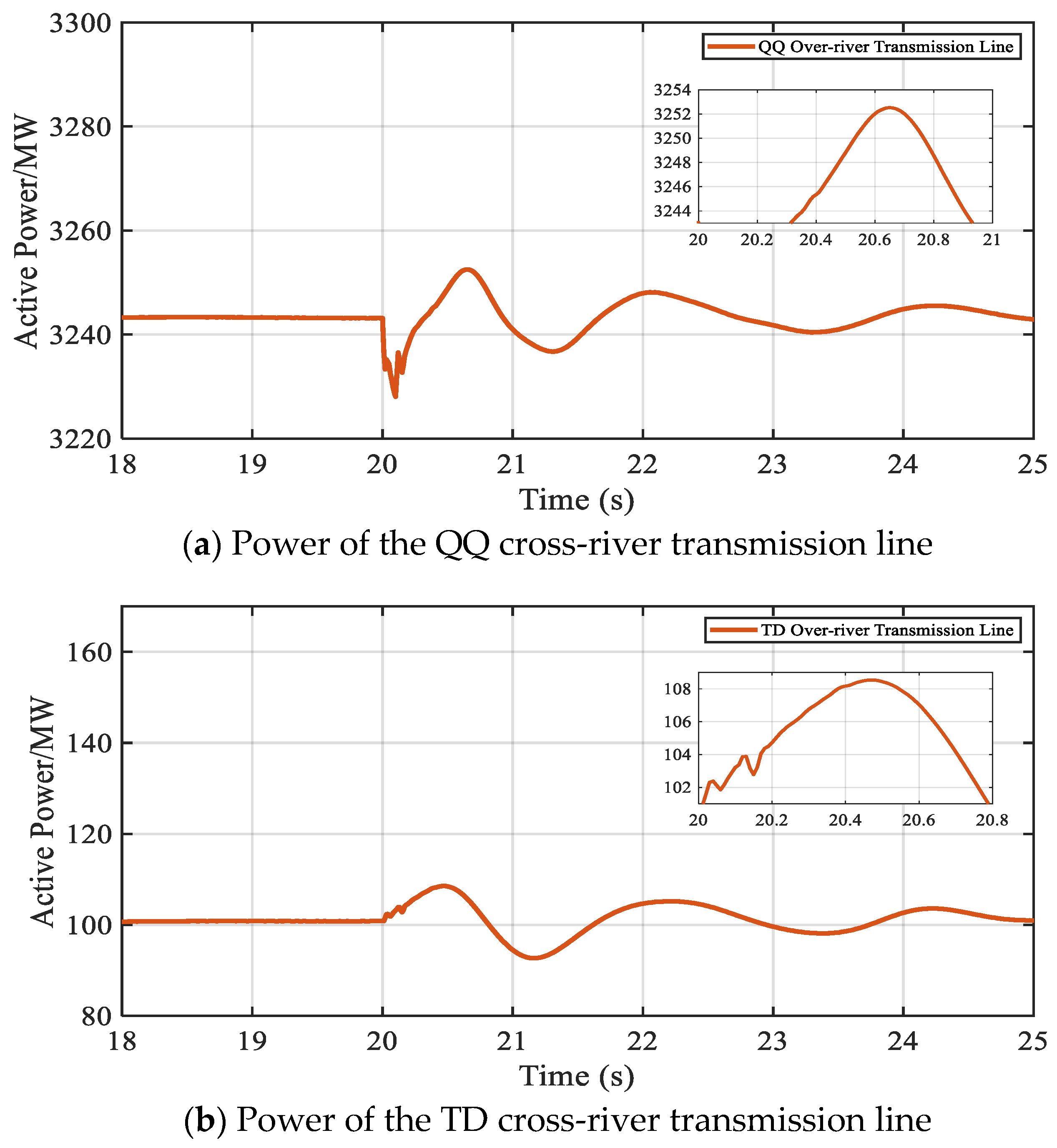
The QQ and TD transmission lines experience only minor power fluctuations, as shown in Figure 16. In the TD transmission line, the transmitted power increases by just 9%, indicating that, with the support of the CLCCs, the grid can effectively handle faults and restore stability. Specifically, in the TD transmission line, due to its smaller transmission capacity, the increase in power does not have a significant impact on the transmission stability of the channel, ensuring the normal operation of the regional power grid.
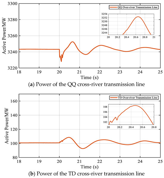
Figure 16.
Power of the distant cross-river transmission channels of the YZ-ZJ DC project under AC fault conditions after replacing the receiving-end converters with CLCCs.
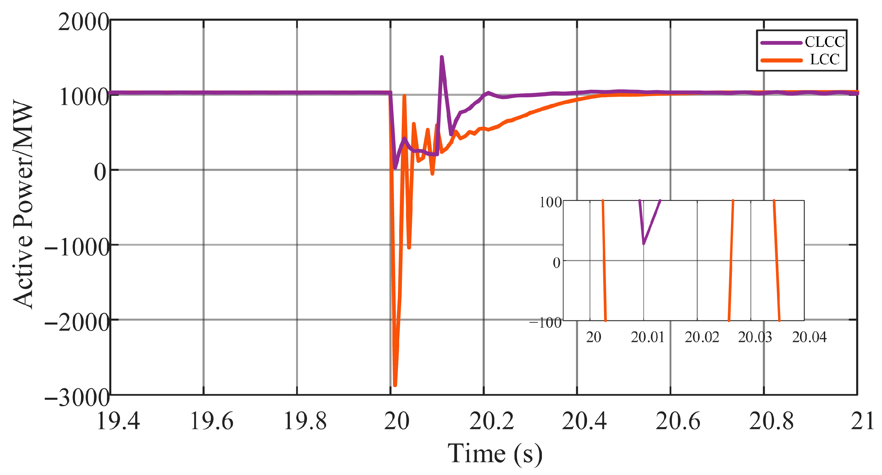
Consider the operating conditions of the YZ-ZJ DC project under a 1000 MW load during the summer peak period. At 20 s, a more severe three-phase to ground fault is applied to the receiving-end AC system, lasting for 0.1 s. At this point, the traditional LCC station still experiences commutation failure and the uncontrolled conduction of the converter valve leads to a more severe power reversal, seriously affecting the safe and stable operation of the system. In contrast, the modified CLCC station, even under these more severe conditions, does not experience commutation failure and can maintain a lower power transmission, as shown in Figure 17.

Figure 17.
Transmission power of the YZ-ZJ DC project at the receiving end with two types of converters under three-phase to ground fault conditions.
At this point, due to the energy dissipation effect of the surge arrester in the auxiliary branch, the CLCC does not experience commutation failure and the valve current remains continuous. Although the DC current fluctuates and the DC voltage drops more than in the case of a single-phase fault, it is still able to maintain a certain voltage level and does not fall to zero, as shown in Figure 18.

Figure 18.
Electrical characteristics of the YZ-ZJ DC project with CLCCs at the receiving end under three-phase to ground fault conditions.
At this point, for the two cross-river transmission channels in close proximity, which are most affected, the occurrence of a severe three-phase grounded fault in the receiving-end AC system of the YZ-ZJ project significantly impacts the power transmission of these two channels, leading to a reduction in transmitted power during the early stages of the fault. During the fault, as shown in Figure 19, the maximum transmission power of the JM channel reaches 2765 MW, while the maximum transmission power of the CL channel reaches 3006 MW, both of which are within the maximum transmission capacity limits of the respective channels, thus not imposing a significant burden on either channel.

Figure 19.
Power of the nearby cross-river transmission channels of the YZ-ZJ DC project under three-phase to ground fault conditions after replacing the receiving-end converters with CLCCs.
5. Discussions
This study demonstrates that CLCCs significantly improve the fault tolerance of HVDC systems. After integrating CLCCs into the YZ-ZJ DC project, the system’s ability to withstand commutation failures was enhanced, ensuring continuous power transmission even during faults. Compared to the integration of traditional LCC-HVDC systems into regional power grids, introducing CLCCs into the receiving-end converter station in this project allows the system to resist commutation failures during faults in the receiving-end AC system, maintaining power transmission without causing power reversal. This has a positive impact on the overall regional grid.
Regarding the power loss after the converter station modification, in practical engineering, the CLCC can disable its auxiliary branch when there are no faults, thus operating in LCC mode, making the operational characteristics and power loss of CLCCs almost identical to those of traditional LCCs. Since the main conducting branch of the CLCC is the primary branch, and this main branch has an added series-connected IGBT valve compared to the LCC, it leads to an increase in conduction losses. However, due to the relatively fewer series-connected IGBT valves, the increase in converter losses does not exceed 10%. Therefore, the total loss of the converter station will increase from the current 0.7% to 0.72%, slightly higher than the LCC station, but this increase is significantly lower than that of other commutation-failure-resistant converter stations (such as MMC) and remains within the acceptable range for engineering applications.
Furthermore, CLCCs not only retain the low loss and high capacity advantages of the original LCC-HVDC system but also provide the ability to resist commutation failures. Compared to existing commutation-failure-resistant converter stations (such as VSCs), CLCCs offers higher economic advantages when achieving the same commutation-failure resistance effect. Therefore, CLCCs not only maintain the benefits of the original system but also have superior economic feasibility.
However, despite the clear advantages of CLCCs, further research is needed to refine control strategies for extreme fault conditions. Additionally, a comprehensive evaluation of the cost-effectiveness of upgrading existing LCC systems to CLCC systems should be conducted, considering both technical and economic factors, to ensure the benefits outweigh the costs.
In conclusion, CLCC technology holds great potential in enhancing HVDC system stability and fault tolerance, but its practical implementation requires careful consideration of the balance between operational performance and cost-effectiveness.
6. Conclusions
This article examines the application of Controllable-Line-Commutated Converters (CLCCs) in the YZ-ZJ DC project at the receiving end, focusing on the electrical characteristics of the YZ-ZJ DC project under receiving-end AC system faults and their impact on the transmission capacity of the remaining cross-river channels within the regional power grid. From the analysis and simulation results, the following conclusions are derived:
- (1)
- The adoption of CLCCs in the YZ-ZJ DC project’s receiving section significantly improves the system’s ability to withstand commutation failures. Unlike traditional LCCs, which may experience commutation failures during faults in the AC system, CLCCs maintain stable power transmission by operating in forced commutation mode. This improvement ensures that the regional grid continues to operate during faults, reducing the risk of power outages.
- (2)
- CLCCs significantly reduce the power fluctuations in the remaining cross-river transmission channels under fault conditions, particularly in cross-river channels such as CL and JM, which are geographically close. The upgraded YZ-ZJ DC project, with the receiving-end CLCCs operating in forced commutation mode, effectively resists commutation failures and maintains certain levels of power transmission during faults, ensuring smoother system operation.
- (3)
- After replacing the LCCs with CLCCs in the YZ-ZJ DC project’s receiving section, the power distribution across cross-river transmission channels has been optimized under fault conditions. This alleviates the transmission pressure on smaller capacity cross-river channels, such as the TD channel, during faults, thereby improving grid stability.
- (4)
- Simulation results indicate that CLCCs outperform LCCs under fault conditions, maintaining continuous and stable power transmission. This ensures the stability of the YZ-ZJ DC project, as the system can continue to operate during grid faults, enhancing the long-term reliability of the regional power grid.
Despite its promising results, this study is limited to offline simulations based on a static fault scenario and specific grid configuration. Real-time dynamic interactions, hardware-in-the-loop validation, and the impact of large-scale renewable integration remain unaddressed. Future research should focus on the following:
- (1)
- Developing adaptive control strategies for CLCCs under varying grid conditions;
- (2)
- Assessing the long-term reliability and protection coordination of CLCCs in multi-terminal HVDC systems;
- (3)
- Investigating the long-term operational reliability of CLCCs in multi-infeed HVDC systems;
- (4)
- Enhancing the YZ-ZJ project’s ability to withstand commutation failure will increase the capacity for transmitting renewable energy from Jiangbei to Jiangnan. Future studies could explore risk-averse energy management and the Asymmetric Nash Bargaining Approach, as mentioned in references [25,26], to fully optimize the economic potential of power transmission.
Author Contributions
Conceptualization, K.L. and B.L.; methodology, K.L. and B.L.; software, K.L. and B.L.; validation, K.L. and B.L.; data curation, K.L. and B.L.; writing—original draft preparation, K.L.; writing—review and editing, K.L. and B.L.; supervision, B.L.; project administration, B.L. and Q.J. All authors have read and agreed to the published version of the manuscript.
Funding
This work is supported by Natural Science Foundation of Sichuan Province (No. 2025ZNSFSC0450) and also supported by Sichuan Science and Technology Program (2024NSFSC0865).
Data Availability Statement
Available upon reasonable request.
Conflicts of Interest
The authors declare no conflicts of interest.
References
- Tang, G.; Zhou, J.; Pang, H.; Lin, J.; Fan, Z.; Wu, Y.; He, Z.; Ma, S.; Xue, F.; Zhou, B. Development Strategy Framework of New Power Systems under the Energy Security Pattern. China Eng. Sci. 2023, 25, 79–88. [Google Scholar]
- Zhou, Y.X.; Chen, J.N.; Zhang, L.; Zhang, Y.X.; Teng, C.Y.; Huang, X. Development Opportunities for Ultra-High Voltage Transmission Technology under the Background of “Dual Carbon” and “New Infrastructure”. High Volt. Eng. 2021, 47, 2396–2408. [Google Scholar]
- Sellick, R.; Åkerberg, M. Comparison of HVDC light (VSC) and HVDC classic (LCC) site aspects for a 500MW 400kV HVDC transmission scheme. In Proceedings of the 10th IET International Conference on AC and DC Power Transmission (ACDC 2012), Birmingham, UK, 4–5 December 2012; pp. 1–6. [Google Scholar]
- Yamashita, K.-i.; Morioka, T.; Fukumoto, K.; Nishikata, S. A high-voltage direct current transmission system using a 12-pulse thyristor inverter without AC grids’ low-order harmonic distortions. In Proceedings of the 2016 19th International Conference on Electrical Machines and Systems (ICEMS), Chiba, Japan, 13–16 November 2016; pp. 1–5. [Google Scholar]
- Thio, C.V.; Davies, J.B.; Kent, K.L. Commutation failures in HVDC transmission systems. IEEE Trans. Power Deliv. 1996, 11, 946–957. [Google Scholar] [CrossRef]
- Wei, Z.; Yuan, Y.; Lei, X.; Wang, H.; Sun, G.; Sun, Y. Direct-Current Predictive Control Strategy for Inhibiting Commutation Failure in HVDC Converter. IEEE Trans. Power Syst. 2014, 29, 2409–2417. [Google Scholar] [CrossRef]
- Zhou, H.; Yao, W.; Ai, X.; Li, D.; Wen, J.; Li, C. Comprehensive review of commutation failure in HVDC transmission systems. Electric Power Syst. Res. 2022, 205, 107768. [Google Scholar] [CrossRef]
- Li, T.; Zhao, T.; Lv, M.; Zou, L.; Zhang, L. The mechanism and solution of the anomalous commutation failure of multi-infeed HVDC transmission systems. Int. J. Electr. Power Energy Syst. 2020, 114, 105400. [Google Scholar] [CrossRef]
- Jing, L.; Wang, B.; Dong, X.; Wang, H.G.; Yu, B.; Xie, M.; Chen, S. Review of consecutive commutation failure research for HVDC transmission system. Electric Power Autom. Equip. 2019, 39, 116–123. [Google Scholar]
- Deb, S.; Lata, S.; Bhadoria, V.S.; Tiwari, S.; Maris, T.I.; Vita, V.; Fotis, G. Improved Relay Algorithm for Detection and Classification of Transmission Line Faults in Monopolar HVDC Transmission System Using Signum Function of Transient Energy. IEEE Access 2024, 12, 15561–15571. [Google Scholar] [CrossRef]
- Zhang, L.; Dofnas, L. A novel method to mitigate commutation failures in HVDC systems. In Proceedings of the Proceedings. International Conference on Power System Technology, Kunming, China, 13–17 October 2002; Volume 1, pp. 51–56. [Google Scholar] [CrossRef]
- Xing, C.; Xi, X.; He, X.; Xu, Z.; Li, S.; Xiang, C. An Interactive Control Strategy of STATCOM and VDCOL for Suppressing Weak Receiving Commutation Failure of HVDC. In Proceedings of the 2021 IEEE 4th International Electrical and Energy Conference (CIEEC), Wuhan, China, 28–30 May 2021; pp. 1–6. [Google Scholar] [CrossRef]
- Zhou, H.; Yao, W.; Li, C.; Wen, J. A Predictive Voltage Dependent Current Order Limiter with the Ability to Reduce the Risk of First Commutation Failure of HVDC. High Volt. Eng. 2021, 48, 3179–3318. [Google Scholar]
- Guo, C.; Liu, Y.; Zhao, C.; Wei, X.; Xu, W. Power component fault detection method and improved current order limiter control for commutation failure mitigation in HVDC. IEEE Trans. Power Delivery 2015, 30, 1585–1593. [Google Scholar] [CrossRef]
- Xue, Y.; Zhang, X.-P.; Yang, C. Elimination of Commutation Failures of LCC HVDC System with Controllable Capacitors. IEEE Trans. Power Syst. 2016, 31, 3289–3299. [Google Scholar] [CrossRef]
- Xue, Y.; Zhang, X.-P.; Yang, C. Commutation Failure Elimination of LCC HVDC Systems Using Thyristor-Based Controllable Capacitors. IEEE Trans. Power Deliv. 2018, 33, 1448–1458. [Google Scholar] [CrossRef]
- Weimin, M.; Ling, W.; Ming, L. SLCC Converter Technology of UHVDC Transmission in New Power System. High Volt. Eng. 2022, 48, 4941–4948. [Google Scholar] [CrossRef]
- Xu, R.; Jiang, Q.; Kuang, W.; Zheng, J.; Li, B.; Peng, Q.; Nan, L. Analysis and control method of SLCC-HVDC system oriented to retrofit AC transmission lines. In Proceedings of the 2024 3rd International Conference on Power Systems and Electrical Technology (PSET), Tokyo, Japan, 5–8 August 2024; pp. 268–272. [Google Scholar] [CrossRef]
- Gao, C.; Yang, J.; He, Z.; Tang, G.; Zhang, J.; Li, T.; He, D. Novel Controllable-Line-Commutated Converter for Eliminating Commutation Failures of LCC-HVDC System. IEEE Trans. Power Deliv. 2023, 38, 255–267. [Google Scholar] [CrossRef]
- Povh, D.; Thepparat, P.; Westermann, D. Further development of HVDC control. In Proceedings of the 2011 IEEE Trondheim PowerTech, Trondheim, Norway, 19–23 June 2011; pp. 1–8. [Google Scholar] [CrossRef]
- Li, H.; Li, X.; Ge, B.; Sun, X. Enhanced constant extinction angle control for subsequent commutation failure in LCC-HVDC. IET Gener. Transm. Distrib. 2025, 19, e13356. [Google Scholar] [CrossRef]
- Zengping, W.; Xiyang, L.; Bowen, Z. The Research on Fast Prediction and Suppression Measures of Commutation Failure Based on Voltage Waveform Fitting. Trans. China Electrotech. Soc. 2020, 35, 1454–1463. [Google Scholar] [CrossRef]
- Zhu, R.; Zhou, X.; Luo, A.; Hong, L.; Xia, H.; Deng, L. Commutation Failure Mitigation Method Based on Voltage-Time Commutation Area Prediction. Autom. Electr. Power Syst. 2022, 46, 156–163. [Google Scholar]
- Xiao, H.; Li, Y.; Duan, X. Enhanced Commutation Failure Predictive Detection Method and Control Strategy in Multi-Infeed LCC-HVDC Systems Considering Voltage Harmonics. IEEE Trans. Power Syst. 2021, 36, 81–96. [Google Scholar] [CrossRef]
- Zhai, X.; Li, Z.; Li, Z.; Xue, Y.; Chang, X.; Su, J.; Jin, X.; Wang, P.; Sun, H. Risk-averse energy management for integrated electricity and heat systems considering building heating vertical imbalance: An asynchronous decentralized approach. Appl. Energy 2025, 383, 125271. [Google Scholar] [CrossRef]
- Ding, B.; Li, Z.; Li, Z.; Xue, Y.; Chang, X.; Su, J.; Sun, H. Cooperative operation for multi-agent energy systems integrated with wind, hydrogen, and buildings: An asymmetric Nash bargaining approach. IEEE Trans. Ind. Inform. 2025. [Google Scholar] [CrossRef]


Disclaimer/Publisher’s Note: The statements, opinions and data contained in all publications are solely those of the individual author(s) and contributor(s) and not of MDPI and/or the editor(s). MDPI and/or the editor(s) disclaim responsibility for any injury to people or property resulting from any ideas, methods, instructions or products referred to in the content. |
© 2025 by the authors. Licensee MDPI, Basel, Switzerland. This article is an open access article distributed under the terms and conditions of the Creative Commons Attribution (CC BY) license (https://creativecommons.org/licenses/by/4.0/).