Article

Experimental Validation and Optimization of a Hydrogen–Gasoline Dual-Fuel Combustion Model in a Spark Ignition Engine with a Moderate Hydrogen Ratio

1
Department of Innovative Vehicles and Materials, GAMF Faculty of Mechanical Engineering and Computer Science, John von Neumann University, H-6000 Kecskemét, Hungary
2
BDN Automotive Kft., H-9025 Győr, Hungary
3
Department of Propulsion Technology, Széchenyi István University, H-9026 Győr, Hungary
4
Department of Road and Rail Vehicles, Zalaegerszeg Innovation Park, Széchenyi István University, H-9026 Győr, Hungary
*
Author to whom correspondence should be addressed.
Energies 2025, 18(13), 3501; https://doi.org/10.3390/en18133501
Submission received: 26 May 2025 / Revised: 23 June 2025 / Accepted: 30 June 2025 / Published: 2 July 2025
(This article belongs to the Special Issue Performance and Emissions of Advanced Fuels in Combustion Engines)

Abstract

Hydrogen–gasoline dual-fuel spark ignition (SI) engines represent a promising transitional solution toward cleaner combustion and reduced carbon emissions. In a previous study, a predictive engine model was developed to simulate the performance and combustion characteristics of such systems; however, its accuracy was constrained by the use of estimated combustion parameters. This study presents an experimental validation based on high-resolution in-cylinder pressure measurements performed on a naturally aspirated SI engine operating with a 20% hydrogen energy share. The objectives are twofold: (1) to refine the combustion model using empirically derived combustion metrics, and (2) to evaluate the feasibility of moderate hydrogen enrichment in a stock engine configuration. To facilitate a more accurate understanding of how key combustion parameters evolve under different operating conditions, Vibe function was fitted to the ensemble-averaged heat release rate curves computed from 100 consecutive engine cycles at each static full-load operating point. This approach enabled the extraction of stable and representative metrics, including the mass fraction burned at 50% (MFB50) and combustion duration, which were then used to recalibrate the predictive combustion model. In addition, cycle-to-cycle variation and combustion duration were also investigated in the dual-fuel mode. The combustion duration exhibited a consistent and substantial reduction across all of the examined operating points when compared to pure gasoline operation. Furthermore, the cycle-to-cycle variation difference remained statistically insignificant, indicating that the introduction of 20% hydrogen did not adversely affect combustion stability. In addition to improving model accuracy, this work investigates the occurrence of abnormal combustion phenomena—including backfiring, auto-ignition, and knock—under enriched conditions. The results confirm that 20% hydrogen blends can be safely utilized in standard engine architectures, yielding faster combustion and reduced burn durations. The validated model offers a reliable foundation for further dual-fuel optimization and supports the broader integration of hydrogen into conventional internal combustion platforms.

1. Introduction

The pursuit of sustainable, low-carbon transportation has spurred intense interest in hydrogen as an alternative fuel for internal combustion engines. Hydrogen’s combustion is carbon-free, producing only water vapor as a byproduct, which offers the potential for drastically reducing greenhouse gas emissions compared to conventional fossil fuels [1,2]. It also has high specific energy content and can be produced from renewable or waste-based sources [3,4], positioning it as a key transitional energy vector. The integration of hydrogen into conventional spark-ignition (SI) engines—particularly in dual-fuel configurations—has gained attention as a practical near-term solution to lower carbon emissions [5]. Hydrogen’s beneficial combustion properties include a wide flammability range, low ignition energy, and a high laminar flame speed, which enable ultra-lean and faster combustion [6,7]. Studies have shown that even moderate hydrogen addition (~10–30% energy share) improves brake thermal efficiency, reduces unburnt hydrocarbons and carbon monoxide, and accelerates burn rates [8,9,10]. In particular, Qin et al. reported that dual-fuel hydrogen–diesel combustion improved thermal efficiency while maintaining combustion stability, and similar observations have been made for gasoline-based systems [4,11,12]. Hydrogen–gasoline dual-fuel engines also exhibit significant reductions in particulate emissions and CO2 output, as observed by several experimental campaigns [13,14].
Despite these advantages, hydrogen’s low ignition energy and high diffusivity increase the risk of abnormal combustion phenomena such as backfire, knock, and pre-ignition, especially at high hydrogen fractions or under elevated intake temperatures [15,16,17]. These issues are especially prevalent in port fuel injection (PFI) systems, where premixed hydrogen–air enters the cylinder via the intake manifold [18,19,20]. To mitigate these risks, strategies such as spark timing retardation, cooled exhaust gas recirculation (EGR), and flame arrestors have been proposed [21,22]. More recently, direct injection (DI) of hydrogen has shown promising potential to reduce volumetric efficiency penalties while avoiding backfire and improving power output [8,9,23]. Advanced control techniques are also critical in dual-fuel engines. Experimental studies have demonstrated that precise ignition phasing, optimized valve timing, and custom camshaft profiles can significantly influence knock resistance and thermal efficiency [24,25,26]. High-speed diagnostics combined with combustion modeling have improved understanding of cycle-to-cycle variability and auto-ignition trends under hydrogen-rich conditions [27,28]. Complementary studies have examined hydrogen blending with biodiesel, ethanol, and even pyrolysis oils to investigate multicomponent dual-fuel strategies [29,30]. These combinations introduce additional combustion complexity, but may offer synergistic benefits in emissions and engine performance [11,31,32]. For instance, studies on fatty acid esters and HVO blends demonstrated altered ignition delay and soot formation trends when hydrogen was added to the charge [33,34]. More broadly, research on biodiesel–hydrogen combinations has shown that biofuels can stabilize combustion while hydrogen enhances reactivity under lean conditions [35,36].
Computational models have become indispensable in analyzing dual-fuel combustion. Approaches ranging from zero-dimensional heat-release models to detailed CFD simulations have been developed to predict ignition delay, burn rate, knock, and emissions [37]. However, these models must be calibrated and validated using experimental pressure data to achieve acceptable prediction accuracy. In one notable study, simulation fidelity improved substantially when MFB50 and burn duration were fitted to real engine traces [5]. Moreover, simulation tools like AVL BOOST and GT-Power are commonly used for engine development, but even these require experimental input for boundary conditions and combustion descriptors. Supporting this view, Verhelst and Turner emphasize the importance of combined experimental–numerical workflows for low-carbon SI engine development [10]. Similarly, other works argue that reliance on empirical correlations or default parameterizations leads to large uncertainties under hydrogen-rich regimes [29]. In light of these findings, the present study aims to experimentally validate a simulation-based hydrogen–gasoline dual-fuel combustion model under realistic, moderate hydrogen enrichment conditions. A 20% hydrogen energy share was selected based on prior work, indicating that it offers a strong balance between efficiency gains and combustion stability [9]. In-cylinder pressure data were collected across a range of engine speeds and loads to extract key combustion parameters, including MFB50, burn duration, and peak pressure timing. These were then used to recalibrate a predictive Vibe-function-based combustion model implemented in AVL CRUISE M.
Unlike many prior models that assume constant combustion characteristics at fixed hydrogen ratios, the present work accounts for load- and speed-dependent burn trends, revealing that hydrogen addition does not produce a fixed-duration flame propagation profile. Instead, burn duration contracts at lower speeds and flattens at higher ones. Importantly, throughout testing, no signs of knock, pre-ignition, or backfire were detected. These results reinforce the feasibility of 20% hydrogen blending in conventional SI architectures, supporting the safe and effective integration of hydrogen into current engine technology platforms. In this study, we present the experimental validation of simulated combustion parameters in a hydrogen–gasoline dual-fuel SI engine. The engine was operated with 10% and 20% hydrogen energy share ratios, representing practical and conservative enrichment levels. In-cylinder pressure data were used to extract key combustion descriptors, refine the model’s Vibe parameter assumptions, and assess real-world behavior, including backfiring, auto-ignition, and knock tendency. Special attention was given to evaluating whether these hydrogen ratios are fully compatible with stock engine hardware without requiring significant design changes. The results aim to enhance the predictive capability of dual-fuel engine simulations and inform us of the practical limits for hydrogen co-firing under current ICE architectures. The validated model will serve as a reliable tool for further dual-fuel optimization and help to de-risk hydrogen integration pathways during the infrastructure build-up phase. The following sections describe the methodology, model formulation, experimental validation setup, and calibration strategy. Special attention is given to how hydrogen alters combustion timing, pressure-rise rate, and engine-out emissions under predefined full-load working points.
This study presents a comprehensive experimental validation of a hydrogen–gasoline dual-fuel combustion model using in-cylinder pressure data, with a particular focus on moderate hydrogen enrichment under stoichiometric conditions. Unlike previous works that rely on assumed or constant-duration heat-release characteristics, this study refines the combustion model based on pressure-derived descriptors, such as MFB50 and burn duration, across multiple load points. The novelty of this work lies in the use of high-resolution combustion data to recalibrate a two-zone Vibe-based simulation model, enabling more accurate prediction of dual-fuel combustion dynamics. Furthermore, this study assesses the operational feasibility of hydrogen enrichment in an unmodified stock engine platform, contributing both to model accuracy and to the practical evaluation of hydrogen integration pathways in existing SI engine architectures.

2. Materials and Methods

2.1. Materials

2.1.1. Engine

The simulation model and corresponding experimental investigations were carried out using a BMW M43B18 internal combustion engine. This engine was chosen for its extensively documented characteristics and proven reliability in both virtual modeling and practical testing environments. Prior to initiating the experimental phase, the engine underwent a comprehensive refurbishment to ensure precise and consistent measurement results. This process included a detailed inspection and restoration of all major engine components, namely, the cylinder head, pistons, connecting rods, and crankshaft. In the cylinder head, we replaced the valve guides and valves, re-machined the valve seats, and resurfaced the mating surface. Each cylinder of the engine block was re-honed, and the mating surface was ground flat. The crankshaft and camshaft were polished. All piston rings, bearings, and gaskets were replaced with new ones. As for the other mechanical components, after cleaning and visual inspection, we determined that they were in acceptable condition. Any worn or defective parts were replaced with new, OEM-standard components, thereby restoring the engine to its original factory condition.
Following the renovation, the engine was subjected to a carefully controlled run-in procedure, in accordance with the guidelines provided by MAHLE [37]. This break-in phase was critical to the stabilization of the engine’s mechanical behavior and to ensure smooth, efficient operation under load. The procedure spanned several hours, during which the engine was gradually brought up to operational speed and load levels, allowing for the newly installed components to properly seat and function under realistic conditions. The key technical specifications of the internal combustion engine used in this study are presented in Table 1. These parameters are not changed under the dual-fuel operation.

2.1.2. Engine Control Unit and Wiring

To facilitate the experimental setup, a custom wiring harness was designed and assembled to integrate a standalone, programmable engine control unit (ECU). This configuration provided the flexibility to monitor and dynamically adjust the engine’s operating parameters in real-time, including fuel injection and ignition timing. The selected ECU was chosen for its advanced capabilities and adaptability, offering essential features such as wideband oxygen sensor compatibility and real-time fuel and ignition mapping. These functions are particularly critical for fine-tuning performance in complex operating scenarios, such as gasoline–hydrogen dual-fuel modes. The custom harness ensured stable and accurate communication between the ECU and all relevant engine sensors and actuators, thereby enabling reliable and precise engine management throughout the testing process.

2.1.3. Combustion Analyzer

To ensure peak engine performance while remaining below the knock threshold, and to develop a highly accurate simulation model, a comprehensive series of combustion tests was conducted using a specialized diagnostic system from BDN Automotive. This system is specifically engineered to capture high-resolution, time-synchronized combustion data an essential requirement for understanding the complex thermodynamic behavior of internal combustion and for calibrating simulation models to accurately reflect real-world engine responses.
At the heart of the system is the CA-6 six-channel combustion analyzer, a state-of-the-art device capable of simultaneously recording combustion data from multiple sources (Table 2). This enables the detailed monitoring of critical parameters, such as in-cylinder pressure, rate of heat release, and combustion duration, across a broad spectrum of engine operating conditions. The analyzer is paired with an AVL indication spark plug, a precision instrument embedded with high-sensitivity sensors capable of withstanding the extreme thermal and pressure conditions typical within the combustion chamber. The spark plug is connected to an AVL charge amplifier, which amplifies the sensor signals to a level appropriate for accurate digitization and analysis, thereby ensuring that even subtle variations in combustion pressure are reliably captured. The system operates at a sampling rate of 1 MHz (one million samples per second), which is vital for capturing the rapid transients associated with combustion. This exceptionally high temporal resolution enables crank-angle-based analysis of key combustion metrics, including peak pressure, the location of peak pressure, and the mass fraction burned. These indicators are critical for assessing engine performance and refining the predictive capabilities of the simulation model. Accurate crank-angle synchronization is achieved using the engine’s existing 60-2 pattern crank trigger wheel. This toothed wheel, mounted on the crankshaft, features 60 teeth with 2 intentionally omitted to provide a reference signal, enabling the precise determination of the crankshaft position in real-time. By aligning the combustion data with this positional reference, all measurements are accurately phase-locked to the engine’s operating cycle. The resulting dataset offers a high-fidelity view of the combustion process across each cycle. This empirical data is then used to construct and calibrate a detailed simulation model, which serves as a powerful tool for predicting engine performance, diagnosing inefficiencies, and evaluating the impact of potential design changes, such as modifications to valve timing, ignition strategy, or fuel composition.

2.1.4. Fuel

For experimental investigations, the engine was operated in a dual-fuel mode utilizing both commercially available 95-octane gasoline and high-purity hydrogen. The gasoline, commonly referred to as Euro 95 or Regular Unleaded, was selected due to its widespread availability, balanced performance, and well-documented resistance to engine knock. Its use in this study provides a practical benchmark, ensuring that the results are directly translatable to real-world applications and consumer-grade fuel standards. To maintain the integrity and reproducibility of the measurements, both fuels were handled under stringent quality control conditions. The gasoline was sourced from a reputable supplier and stored in sealed, temperature-regulated containers to prevent contamination or degradation. Prior to each test cycle, the gasoline was conditioned to a uniform temperature to avoid density variations caused by thermal fluctuations, which could influence injection mass and combustion dynamics. Similarly, hydrogen was supplied from certified high-pressure cylinders and passed through a pressure regulation and flow control system to ensure accurate dosing during engine operation. The introduction of hydrogen was carefully calibrated to achieve the desired equivalence ratios while maintaining combustion stability and avoiding pre-ignition or abnormal combustion phenomena.

2.1.5. Environment

Throughout the measurement process, stringent control of environmental conditions was maintained to ensure the precision and reproducibility of the experimental results. Ambient temperature and atmospheric pressure are known to have a significant impact on internal combustion engine behavior, as they directly influence the density of the intake air and, consequently, the combustion process, power output, and overall engine efficiency. To mitigate the influence of these external variables and isolate the effects of the tested parameters, both ambient temperature and air pressure were stabilized and held constant for the duration of all test procedures. The specific environmental conditions under which the experiments were conducted are detailed in Table 3.

2.1.6. Hydrogen Supply and Safety System

To enable hydrogen co-firing, a secondary fuel delivery system was installed.
This included the following:
  • Hydrogen injectors mounted in the intake runners 50 mm from the intake valves;
  • A hydrogen mass flow meter for accurate fuel energy share control;
  • A pressure regulator, used to maintain steady delivery pressure across the operating range;
  • A high-pressure hydrogen storage tank, connected via certified high-pressure tubing.
The hydrogen injectors were synchronized with the standalone control unit to deliver precise quantities of hydrogen, in accordance with the desired energy ratio. The system allowed for stable operation without requiring hardware changes to the combustion chamber or ignition system. Given the high diffusivity, wide combustibility range, and low ignition energy of hydrogen, appropriate safety measures were implemented throughout the experimental setup.
These included the following:
  • Gas detection sensors in the test cell to monitor potential hydrogen leaks (Lower Explosion Limit Sensor);
  • Ventilation systems designed to prevent gas accumulation;
  • Pressure relief valves and burst disks on the hydrogen tank and supply lines;
  • Use of certified high-pressure components (tubing, fittings, valves);
  • Emergency stop systems and remote shutdown protocols in case of abnormal pressure or detected leakage.
The safety layout followed the established guidelines for laboratory-scale hydrogen combustion research, as described in [38,39,40].

2.2. Methods

2.2.1. Engine Dyno Test with Gasoline and Hydrogen in Dual-Fuel Operation

The dual-fuel validation tests were conducted using a mixture of hydrogen and gasoline, with hydrogen accounting for 20% of the total energy input. The engine was operated across a speed range of 1500–3500 RPM to represent mid-load steady-state conditions typical of real-world driving scenarios. The objective of these tests was to evaluate the effects of hydrogen enrichment on engine performance, combustion behavior, and emissions, using high-precision instrumentation and real-time data acquisition.
Throughout the experiment, a stoichiometric air–fuel mixture (λ = 1) was maintained by appropriately adjusting the gasoline injection duration while precisely controlling the hydrogen flow rate. Spark timing was set near the optimal advance limit, just below the knock threshold, to ensure efficient combustion without inducing pre-ignition. The throttle was kept fully open during all test points to eliminate intake pressure losses and provide a consistent baseline for performance analysis under dual-fuel operation.
Key parameters measured during the tests included engine speed, intake air mass flow, brake power, torque, exhaust gas temperature (EGT), and the individual consumption rates of hydrogen and gasoline. Hydrogen was supplied through a calibrated flow-control system, and gasoline was delivered using a temperature- and pressure-stabilized injection system. The combined fuel delivery ensured precise energy input and consistent stoichiometry throughout the measurements.
To capture the combustion process in real-time, an advanced combustion analysis system was employed, which included in-cylinder pressure measurement, crank-angle synchronization, and high-speed data logging. This enabled the detailed analysis of combustion metrics, such as the rate of heat release, combustion duration, peak pressure location, and mass fraction burned. All combustion events were logged and analyzed live, providing valuable insight into the thermodynamic effects of hydrogen enrichment on the gasoline combustion process.
The engine was mounted on a standard AVL testbed platform (Figure 1, Table 4), which provided a stable and highly controlled environment for the execution of dual-fuel experiments. The fuel delivery system was composed of several precision components from AVL, ensuring accurate metering, conditioning, and regulation of both gasoline and hydrogen inputs. Gasoline flow was measured using the AVL 735S fuel mass flow meter, stabilized to a consistent temperature of 20 °C via the AVL 752C fuel temperature conditioner, and delivered at a constant pressure of 3.5 bar using the AVL 7531.21 fuel module. This setup guaranteed consistent fuel characteristics throughout all measurement points. Intake air mass flow was measured using the AVL Airsonix sensor, with air supplied and conditioned by an AVL air conditioning system to maintain constant temperature and humidity, thereby eliminating external influences on combustion behavior. Engine torque and power output were measured using an AVL DynoRoad 200 eddy current dynamometer, which ensured precise load control and reliable performance measurements across all test conditions. This fully integrated setup enabled synchronized, high-accuracy data acquisition for evaluating the combined effects of hydrogen and gasoline combustion under a range of operating points (Figure 2).

2.2.2. Test Matrix

The test bench included in-cylinder pressure sensors installed in each cylinder head, synchronized with crank-angle signals to allow for high-resolution pressure trace acquisition. Combustion analysis was performed over a minimum of 100 consecutive cycles per test point to obtain cycle-averaged combustion parameters (Table 5). Gasoline was supplied through the original port fuel injection system, calibrated to deliver the base energy share according to the test matrix. Additional instrumentation included sensors for intake manifold pressure and temperature, exhaust gas temperature, and a high-speed data acquisition system. Knock detection was performed via both pressure-based analysis and optional knock sensors mounted on the engine block.

2.2.3. Combustion Analysis

The combustion characteristics were evaluated using in-cylinder pressure data acquired during steady-state engine operation at various hydrogen energy share ratios. Key parameters analyzed included the following:
  • Mass Fraction Burned (MFB) profiles: Derived using the Rassweiler and Withrow method [13], enabling the calculation of combustion phasing metrics such as MFB10, MFB50, and MFB90.
  • Combustion duration: Determined by the interval between MFB10 and MFB90, providing insights into the combustion speed and completeness.
  • Rate of Heat Release (ROHR): Calculated from the pressure data to assess the combustion intensity and identify any abnormal combustion phenomena.
  • Peak in-cylinder pressure and pressure rise rate: Monitored to evaluate the impact of hydrogen addition on combustion dynamics and potential knock tendencies.
Clarification on combustion duration metrics is important to distinguish between the total combustion duration and the MFB90–MFB10 method. In this case, the following parameters were examined:
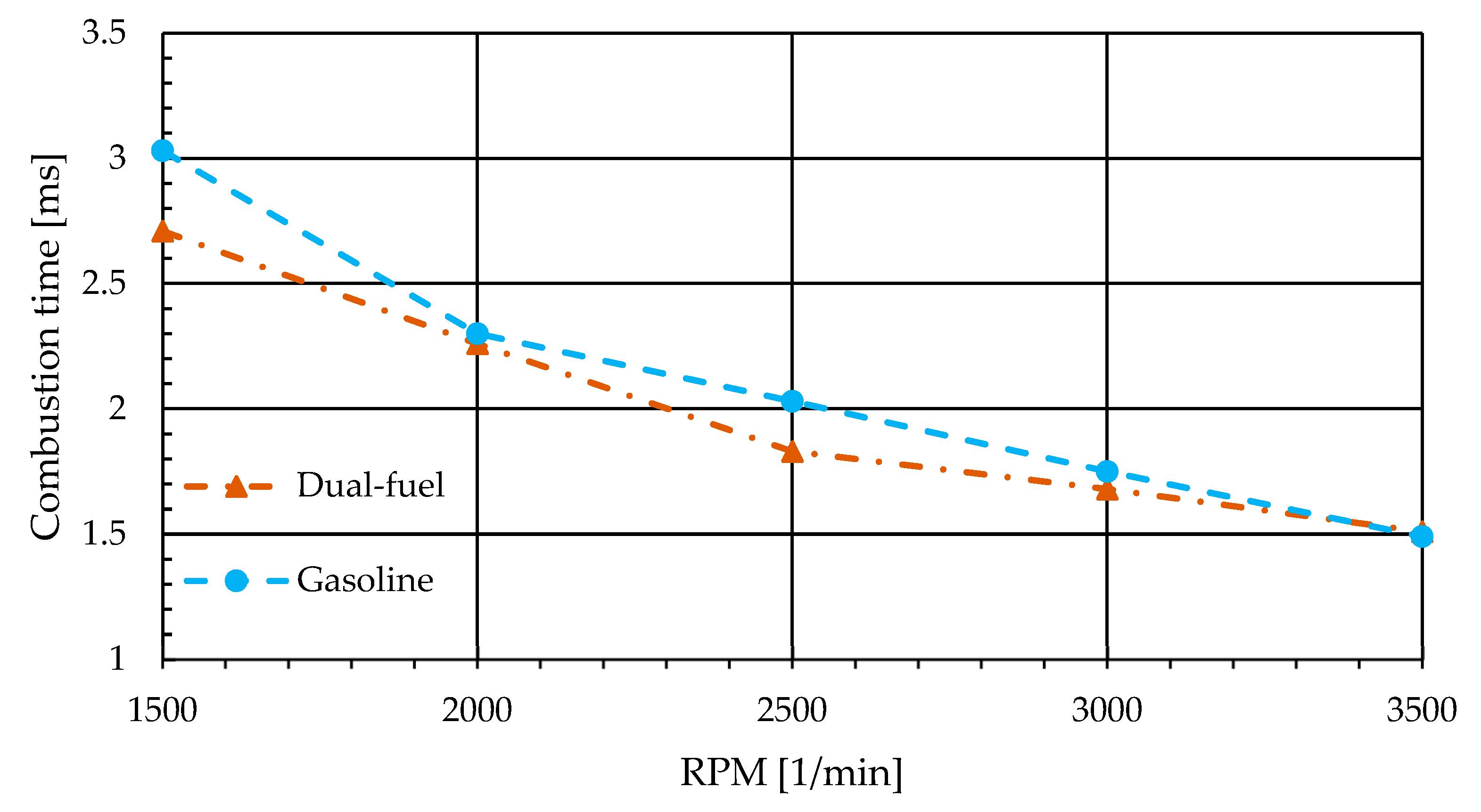
  • Total combustion duration: This refers to the interval between the start of combustion (SOC) and the end of combustion (EOC). The SOC is typically identified as the crank angle at which the first noticeable increase in pressure occurs, while the EOC is when the combustion process concludes. This method captures the entire combustion event, including ignition delay and late-stage combustion.
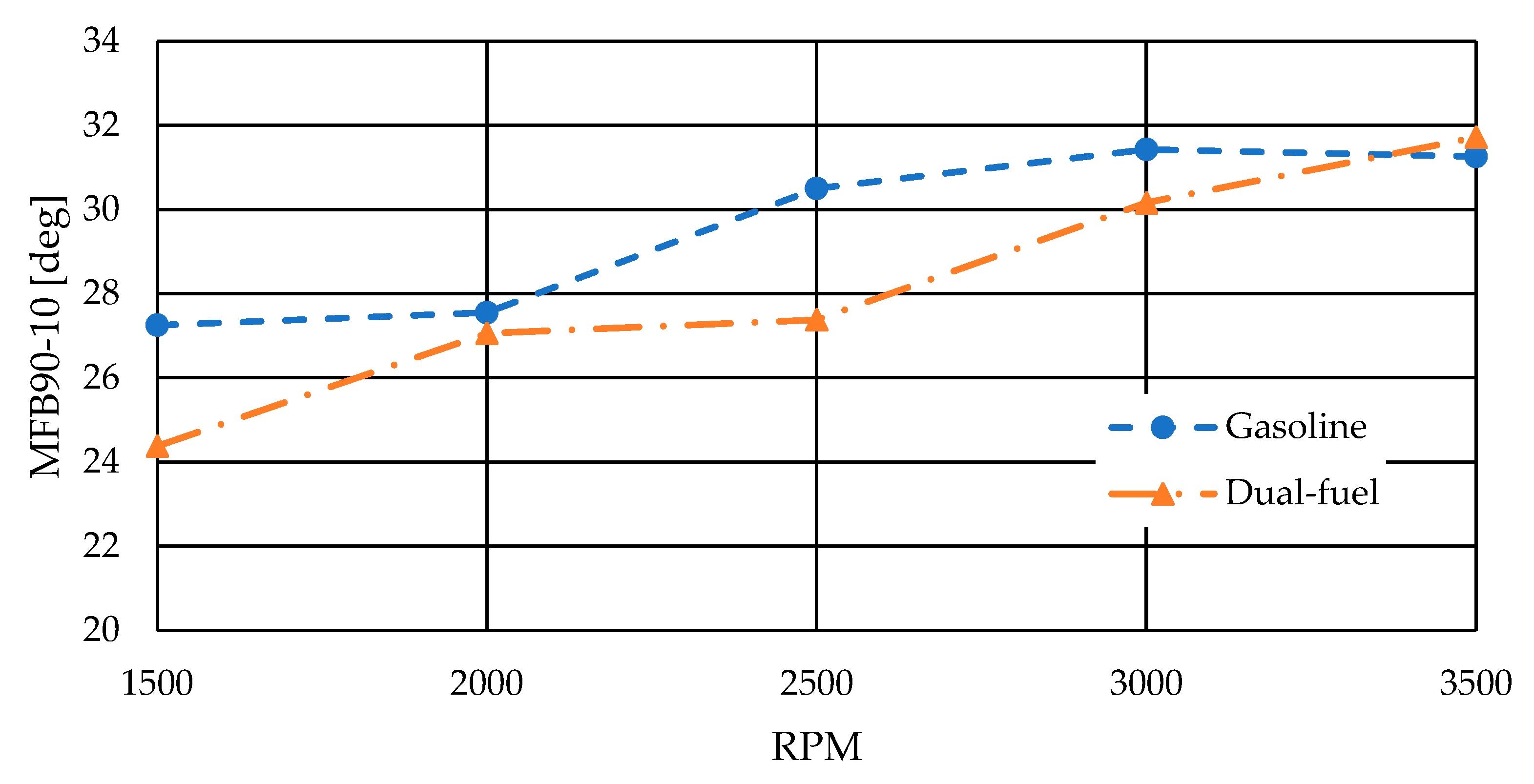
  • MFB90–MFB10 duration: This metric focuses on the interval between 10% and 90% of the mass fraction burned. It effectively captures the main combustion phase, excluding the initial ignition delay and the final stages of combustion. This method is less sensitive to minor fluctuations and provides a consistent basis for comparing combustion speeds across different operating conditions.
The choice between these metrics depends on the specific aspects of combustion being analyzed. For instance, MFB90–MFB10 is particularly useful for assessing the combustion rate and efficiency, while the total combustion duration provides a comprehensive view of the entire combustion process. The analysis revealed that increasing the hydrogen energy share led to a reduction in combustion duration and an advancement in combustion phasing. These changes are attributed to hydrogen’s faster flame propagation, which enhances the combustion process. Similar observations have been reported in the following recent studies:
  • Teodosio et al. (2020) observed that hydrogen port injection in a small turbocharged gasoline engine led to faster combustion rates and improved efficiency due to hydrogen’s favorable combustion properties [41].
  • Sarabi and Aghdam (2019) noted that hydrogen addition in dual-fuel SI engines resulted in shorter combustion durations and advanced combustion phasing, contributing to improved engine performance [42].
  • Kim et al. (2024) investigated the effects of varying equivalence ratios on combustion efficiency and found that hydrogen enrichment led to more stable and efficient combustion with reduced combustion durations [43].
The hydrogen–gasoline dual-fuel engine model developed in AVL CRUISE M was refined using a two-zone Vibe-based combustion model to better capture the distinct characteristics of the unburned and burned gas regions during combustion. This approach allows for a more accurate representation of the combustion process, especially under varying hydrogen enrichment levels [44,45].

2.2.4. Two-Zone Vibe Combustion Model Implementation

In the two-zone model, the combustion chamber is divided into the following:
  • Unburned zone: Contains the air–fuel mixture yet to undergo combustion.
  • Burned zone: Contains the products of combustion.
The heat release rate is modeled using the Vibe function, defined by the shape and location parameters. By adjusting these parameters, the model replicates the combustion curve derived from pressure analysis.
The two-zone approach provides a balance between computational efficiency and accuracy, and has been widely validated for dual-fuel and low-carbon combustion strategies [44,45,46].

2.2.5. Calibration with Experimental Data

Experimental data—including in-cylinder pressure measurements and the derived combustion parameters, such as MFB50 and combustion duration (MFB90–MFB10)—were used to calibrate the model.
The process involved the following:
Aligning combustion phasing: Adjusting the Vibe function’s shape and delay parameters to match experimental MFB50 values.
Matching combustion duration: Calibrating MFB90–MFB10 to capture the main combustion phase.
Validating pressure profiles: Comparing simulated and experimental pressure traces across the crank-angle domain.
This refinement significantly improves model fidelity in capturing hydrogen-induced combustion effects, such as increased flame speed and earlier combustion phasing.

2.2.6. Dual-Fuel Operation Modeling

The dual-fuel mode was modeled with separate fuel energy inputs:
  • The gasoline path retained the original stoichiometric calibration.
  • The hydrogen path was introduced as a premixed gaseous intake injection, using AVL’s user-defined dual-fuel interface, with split ratios based on 10% and 20% hydrogen energy shares.
Fuel input was scaled to maintain constant overall energy delivery (on an LHV basis), isolating the effects of hydrogen combustion characteristics.

3. Results

3.1. Model Refinement in AVL CRUISE M

The refined model was validated against experimental data:
  • In-cylinder pressure: Good alignment with measured pressure curves confirmed the updated burn rate’s accuracy.
  • Combustion phasing and duration: Predicted MFB50 and MFB90–MFB10 closely matched experimental trends.
  • Performance metrics: Simulated brake torque and indicated efficiency were consistent with measured values.
These results demonstrate that the two-zone model, when properly calibrated, accurately reflects dual-fuel combustion under hydrogen enrichment [15,16].

3.2. Testbed Results

The engine was kept in steady load points on the engine dyno with conditioned air temperature, coolant, and oil temperatures. (22 °C, 87 °C, and 100 °C, respectively). In the various load points, 100 combustion cycles were measured, and all the parameters were averaged both for combustion analysis and dyno parameters. The pre-defined ratios were set between gasoline and H2 flows, resulting 20% energy share of the H2; however, we kept the engine’s stochiometric operation. The ignition was controlled in such a way as to keep the engine at the most efficient working point, resulting in the MFB50 value being in a very tight window around 8° ATDC. The applied spark advance had always been smaller in the dual-fuel operation due to the shorter combustion duration, which has already been predicted in the previous paper [47], according to the applied research [48].
Figure 2 shows the combustion duration (MFB90–MFB10) in both gasoline and dual-fuel mode.
From the graph, it is clearly visible that the combustion duration became shorter at most engine speeds; however, it shows a lengthening tendency that is not matched with the predicted queasy-constant combustion duration. The chain-branching radical mechanisms accelerated by hydrogen have a larger effect at slower crank speeds, where ignition delay is more dominant [49]. Hydrogen’s laminar flame speed yields a steeper reduction in combustion duration (Figure 3) at lower engine speeds, but, at higher engine speeds, the reduction becomes smaller as the flame propagation becomes mix- and flow-limited [50,51].
The combustion times show a decreasing tendency with increasing engine speed due to enhanced in-cylinder turbulence and mixture preparation. Trends in combustion duration observed in hydrogen–gasoline dual-fuel operation are consistent with findings in DI diesel–hydrogen dual-fuel engines. Maroteaux et al. (2024) [52] reported that hydrogen addition significantly reduced combustion duration at 1500 rpm, with durations converging to pure diesel values at 2000 RPM. Likewise, studies on CRDi diesel–hydrogen modes confirm that hydrogen’s rapid chemical kinetics dominate at low speeds, while at high speeds, the process becomes mix-limited, reducing duration differences. These parallels support the hypothesis that our measured combustion trends are driven not just by fuel chemistry, but also by the engine speed [52,53]. The coefficient of variation in IMEP has also been calculated to determine if the dual-fuel operation has any influence on the engine’s torques delivery smoothness. The COV IMEP has been calculated (Figure 4).
Calculate mean IMEP: [54]
μ I M E P = 1 N i = 1 N I M E P i
Calculate standard deviation of IMEP: [54]
σ I M E P = 1 N 1 i = 1 N ( I M E P i μ I M E P ) 2
Calculate coefficient of variation: [54]
C O V I M E P = σ I M E P μ I M E P × 100
In most papers, COV values under 3% (Figure 4) were acceptable [32].
It can be stated that the engine performs well in both operational modes, and the dual-fuel operation does not have a significant effect on the COV value. To implement the measured heat-release curves in the engine simulation model and to understand the difference compared to the ones in gasoline operation, Vibe function fitting was performed in all operational points (Figure 5, Table 6). To ensure the best possible fit, R2 values were calculated for each case, with the target being at least 0.9985.
The Vibe parameters for each heat-release curves are as follows:
Adding the measured combustion parameters to the already established AVL Cruise M simulation model, the results could be refined and also validated compared to the test bench measurements (Figure 6). It is clearly visible that the prediction shows a significant amount of difference compared to the measured results, mainly due to the mismatch of the predicted and real heat-release curves.
After the established Vibe parameters was implemented to the model, the correlation improved significantly, resulting in a reliable solid model (Figure 7) that is suitable for further development.

4. Discussion

The experimental results confirm that hydrogen enrichment at a 20% energy share in a spark-ignition engine has a measurable impact on combustion behavior and model accuracy. Contrary to previous simulation predictions that suggest a quasi-constant combustion duration across the speed range, this study demonstrates a mild speed dependency, with shorter combustion durations at lower speeds and a slight increase at higher speeds. This behavior reflects the complex influence of in-cylinder flow fields, ignition delay, and hydrogen reactivity, and underlines the need for pressure-based calibration in predictive models. The refined Vibe-based two-zone model addressed this discrepancy by incorporating experimentally derived heat-release curves. Its ability to reproduce pressure traces and combustion metrics with high fidelity (R2 > 0.9985) confirms its suitability for simulating dual-fuel operation with hydrogen enrichment. Accurate prediction of MFB50 and MFB90–MFB10 durations enables better optimization of ignition timing and efficiency trade-offs in practical calibration scenarios. Importantly, combustion remained highly stable throughout the test matrix, with COV IMEP values consistently below 3%. This indicates that the introduction of hydrogen did not compromise torque stability or cause combustion anomalies. The absence of knock, backfire, or auto-ignition, despite stoichiometric operation and high thermal loads, suggests that moderate hydrogen blending can be safely integrated into stock engine architectures without requiring major mechanical modifications.
The dual-fuel configuration proved capable of delivering predictable and repeatable engine behavior across varying speeds. The test protocol, which included over 100 cycles per point and tightly controlled fuel and environmental conditions, ensured high data quality. These results support the view that hydrogen–gasoline blending can serve not only as a transitional solution, but also as a calibration and modeling benchmark for more advanced dual-fuel or hybrid systems.

5. Conclusions

This study experimentally validates and refines the combustion model of a hydrogen–gasoline dual-fuel spark ignition engine using in-cylinder pressure data under controlled conditions. Operating at 20% hydrogen energy share and stoichiometric air–fuel ratio, the engine demonstrated faster combustion, advanced phasing, and high cycle-to-cycle stability across the test range. With MFB50 values consistently near 8°CA ATDC and COV IMEP below 3%, the system maintained thermodynamic efficiency and smooth operation without triggering knock or other combustion anomalies.
The updated simulation model, incorporating a two-zone Vibe-based heat release profile, showed excellent agreement with measured data (R2 > 0.9985). This improved model fidelity allows for more accurate predictions of combustion phasing, burn duration, and performance metrics such as torque and indicated efficiency. It serves as a validated foundation for the future optimization of hydrogen blending strategies, including cold-start behavior, transient load mapping, and integration with hybrid drivetrains. These findings demonstrate the technical feasibility of moderate hydrogen enrichment in existing internal combustion engines. The validated model will aid in developing control strategies and evaluating emissions profiles under various operating conditions. As the infrastructure for hydrogen production and distribution expands, dual-fuel strategies may offer a scalable and cost-effective pathway for the near-term decarbonization of the transport sector.

Author Contributions

Conceptualization, A.K. and B.S.; methodology, A.K.; software, B.S.; validation, A.K., K.K. and Z.W.; formal analysis, K.K.; investigation, A.K.; resources, A.K.; data curation, B.S. and A.K.; writing—original draft preparation, A.K. and B.S.; writing—review and editing, K.K., Z.W. and B.H.; visualization, A.K.; supervision, K.K., Z.W. and B.H.; project administration, K.K.; funding acquisition, A.K. All authors have read and agreed to the published version of the manuscript.

Funding

This research received no external funding.

Data Availability Statement

The data presented in this study are available on request from the corresponding author. The data are not publicly available due to restrictions imposed by the funding to ensure compliance with data usage agreements.

Acknowledgments

This work was supported by the National Laboratory for Renewable Energy (Project no. RRF-2.3.1-21-2022-00009), which has been implemented with the support provided by the Recovery and Resilience Facility of the European Union within the framework of Program Széchenyi Plan Plus, Hungary.

Conflicts of Interest

The authors declare no conflicts of interest.

References

  1. Chintala, V.; Subramanian, K.A. A comprehensive review on utilization of hydrogen in a compression ignition engine under dual fuel mode. Renew. Sustain. Energy Rev. 2017, 70, 472–491. [Google Scholar] [CrossRef]
  2. Tsujimura, T.; Suzuki, Y. The utilization of hydrogen in hydrogen/diesel dual fuel engine. Int. J. Hydrogen Energy 2017, 42, 14019–14029. [Google Scholar] [CrossRef]
  3. Deheri, C.; Acharya, S.K.; Thatoi, D.N.; Mohanty, A.P. A review on performance of biogas and hydrogen on diesel engine in dual fuel mode. Fuel 2020, 260, 116337. [Google Scholar] [CrossRef]
  4. Qin, Z.; Yang, Z.; Jia, C.; Duan, J.; Wang, L. Experimental study on combustion characteristics of diesel–hydrogen dual-fuel engine. J. Therm. Anal. Calorim. 2020, 142, 1483–1491. [Google Scholar] [CrossRef]
  5. Purayil, S.T.P.; Al-Omari, S.A.B.; Elnajjar, E. Experimental investigation of the effect of CO2 dilution on the performance and hydrogen knock limit of a hydrogen–gasoline dual fuel spark ignition engine 1. Int. J. Hydrogen Energy 2024, 68, 410–427. [Google Scholar] [CrossRef]
  6. Karthic, S.V.; Kumar, M.S.; Pradeep, P.; Kumar, S.V. Assessment of hydrogen-based dual fuel engine on extending knock limiting combustion. Fuel 2020, 260, 116342. [Google Scholar] [CrossRef]
  7. Szamrej, G.; Karczewski, M. Exploring Hydrogen-Enriched Fuels and the Promise of HCNG in Industrial Dual-Fuel Engines. Energies 2024, 17, 1525. [Google Scholar] [CrossRef]
  8. Duan, X.; Feng, L.; Chu, X.; Sun, Z. The performance of a spark ignition gasoline engine with hydrogen addition under low-load conditions. Fuel 2025, 379, 133091. [Google Scholar] [CrossRef]
  9. Mohamed, M.; Biswal, A.; Wang, X.; Zhao, H.; Hall, J. Experimental investigation for enhancing the performance of hydrogen direct injection compared to gasoline in spark ignition engine through valve timings and overlap optimization. Fuel 2024, 372, 132257. [Google Scholar] [CrossRef]
  10. Verhelst, S.; Turner, J.W.G. Hydrogen-Fueled Spark Ignition Engines. In Hydrogen for Future Thermal Engines; Tingas, E.A., Ed.; Green Energy and Technology; Springer: Cham, Switzerland, 2023. [Google Scholar] [CrossRef]
  11. Matla, J.; Kaźmierczak, A.; Haller, P.; Trocki, M. Hydrogen as a fuel for spark ignition combustion engines—State of knowledge and concept. Combust. Engines 2024, 196, 73–79. [Google Scholar] [CrossRef]
  12. Abubakar, S.; Said, M.; Abas, M.; Khalid, A.; Roslan, M.F.; Ismail, N.; Umaru, S.; Narayan, S.; Kaisan, M. Recent progress on hydrogen-fueled port fuel injection spark ignition engine—A systematic review. Therm. Sci. 2025, 00, 81. [Google Scholar] [CrossRef]
  13. Kondor, I.P. Experimental Investigation on the Effect of Heating Oil and Tyre Pyrolysis Oil Combustion in an Evaporative Combustion Chamber. Fuels 2024, 5, 210–221. [Google Scholar] [CrossRef]
  14. Amaral, L.V.; Malaquias, A.C.T.; Fraga, M.A.; Torres, R.B.; Sebastião, R.C.; Pujatti, F.J. Combustion and specific fuel consumption evaluation of a single-cylinder engine fueled with ethanol, gasoline, and a hydrogen-rich mixture. Case Stud. Therm. Eng. 2024, 57, 104316. [Google Scholar] [CrossRef]
  15. Gao, J.; Wang, X.; Song, P.; Tian, G.; Ma, C. Review of the backfire occurrences and control strategies for port hydrogen injection internal combustion engines. Fuel 2022, 307, 121553. [Google Scholar] [CrossRef]
  16. Kumar, M.S.; Muniyappan, M.; Selvan, S.A. Experimental and CFD analysis on the impact of hydrogen as fuel on the behavior of a passenger car gasoline direct injection engine. J. Energy Inst. 2024, 113, 101487. [Google Scholar] [CrossRef]
  17. Hu, Z.; Zhang, Y.; Ai, Z.; Li, M.; Zhang, Y. Hydrogen doping control method for gasoline engine acceleration transient air-fuel ratio. Heliyon 2024, 10, e30865. [Google Scholar] [CrossRef]
  18. Gopal, G.; Srinivasa Rao, P.; Gopalakrishnan, K.V.; Murthy, B.S. Use of hydrogen in dual-fuel engines. Int. J. Hydrogen Energy 1982, 7, 267–272. [Google Scholar] [CrossRef]
  19. Vavra, J.; Bortel, I.; Takats, M. A Dual Fuel Hydrogen-Diesel Compression Ignition Engine and Its Potential Application in Road Transport; No. 2019-01-0564; SAE Technical Paper; SAE International: Warrendale, PA, USA, 2019. [Google Scholar] [CrossRef]
  20. Bakar, R.A.; Widudo; Kadirgama, K.; Ramasamy, D.; Yusaf, T.; Kamarulzaman, M.; Sivaraos; Aslfattahi, N.; Samylingam, L.; Alwayzy, S.H. Experimental analysis on the performance, combustion/emission characteristics of a DI diesel engine using hydrogen in dual fuel mode. Int. J. Hydrogen Energy 2022, 52, 843–860. [Google Scholar] [CrossRef]
  21. Serrano, J.; Jiménez-Espadafor, F.J.; López, A. Analysis of the effect of different hydrogen/diesel ratios on the performance and emissions of a modified compression ignition engine under dual-fuel mode with water injection. Hydrogen-diesel dual-fuel mode. Energy 2019, 172, 702–711. [Google Scholar] [CrossRef]
  22. Saravanan, N.; Nagarajan, G. Experimental investigation on a DI dual fuel engine with hydrogen injection. Int. J. Energy Res. 2009, 33, 295–308. [Google Scholar] [CrossRef]
  23. Rueda-Vázquez, J.M.; Serrano, J.; Pinzi, S.; Jiménez-Espadafor, F.J.; Dorado, M.P. A Review of the Use of Hydrogen in Compression Ignition Engines with Dual-Fuel Technology and Techniques for Reducing NOx Emissions. Sustainability 2024, 16, 3462. [Google Scholar] [CrossRef]
  24. Purayil, S.T.P.; Al-Omari, S.A.B.; Elnajjar, E. Experimental investigation on the influence of gasoline injection pressure on the hydrogen knock limit and performance of a hydrogen–gasoline dual fuel engine. Int. J. Hydrogen Energy 2024, 81, 1385–1393. [Google Scholar] [CrossRef]
  25. Jamshaid, M.; Masjuki, H.H.; Kalam, M.A.; Zulkifli, N.W.M.; Arslan, A.; Zulfattah, Z.M. Effect of fatty acid methyl ester on fuel-injector wear characteristics. J. Biobased Mater. Bioenergy 2020, 14, 327–339. [Google Scholar] [CrossRef]
  26. Gültekin, N.; Ciniviz, M. Examination of the effect of combustion chamber geometry and mixing ratio on engine performance and emissions in a hydrogen-diesel dual-fuel compression-ignition engine. Int. J. Hydrogen Energy 2023, 48, 2801–2820. [Google Scholar] [CrossRef]
  27. Shepel, O.; Matijošius, J.; Rimkus, A.; Duda, K.; Mikulski, M. Research of parameters of a compression ignition engine using various fuel mixtures of hydrotreated vegetable oil (Hvo) and fatty acid esters (fae). Energies 2021, 14, 3077. [Google Scholar] [CrossRef]
  28. Patton, K.J.; Nitschke, R.G.; Heywood, J.B. Development and evaluation of a friction model for spark-ignition engines. SAE Trans. 1989, 98, 1441–1461. [Google Scholar]
  29. Martyr, A.J.; Rogers, D.R. Chapter 16—The combustion process and combustion analysis. In Engine Testing, 5th ed.; Butterworth-Heinemann: Oxford, UK, 2021; pp. 537–597. [Google Scholar] [CrossRef]
  30. Ma, F.; Ding, S.; Wang, Y.; Wang, M.; Jiang, L.; Naeve, N.; Zhao, S. Performance and emission characteristics of a spark-ignition (SI) hydrogen-enriched compressed natural gas (HCNG) engine under various operating conditions including idle conditions. Energy Fuels 2009, 23, 3113–3118. [Google Scholar] [CrossRef]
  31. Iliev, S. A Comparison of Ethanol and Methanol Blending with Gasoline Using a 1-D Engine Model. Procedia Eng. 2015, 100, 1013–1022. [Google Scholar] [CrossRef]
  32. Lawrence, K.R.; Anchupogu, P.; Reddygari, M.R.; Gangula, V.R.; Balasubramanian, D.; Veerasamy, S. Optimization of biodiesel yield and performance investigations on diesel engine powered with hydrogen and acetylene gas injected with enriched Jojoba biodiesel blend. Int. J. Hydrogen Energy 2024, 50, 502–523. [Google Scholar] [CrossRef]
  33. Purayil, S.T.P.; Hamdan, M.O.; Al-Omari, S.A.B.; Selim, M.Y.E.; Elnajjar, E. Review of hydrogen–gasoline SI dual fuel engines: Engine performance and emission. Energy Rep. 2023, 9, 4547–4573. [Google Scholar] [CrossRef]
  34. Pham, P.X.; Bodisco, T.A.; Ristovski, Z.D.; Brown, R.J.; Masri, A.R. The influence of fatty acid methyl ester profiles on inter-cycle variability in a heavy duty compression ignition engine. Fuel 2014, 116, 140–150. [Google Scholar] [CrossRef]
  35. Vass, S.; Zöldy, M. Effects of Boundary Conditions on A Bosch-Type Injection Rate Meter. Transport 2021, 36, 297–304. [Google Scholar] [CrossRef]
  36. Kondor, I.P.; Zöldy, M.; Mihály, D. Experimental Investigation on the Performance and Emission Characteristics of a Compression Ignition Engine Using Waste-Based Tire Pyrolysis Fuel and Diesel Fuel Blends. Energies 2021, 14, 7903. [Google Scholar] [CrossRef]
  37. Engine Break-In: Recommended Procedures. Available online: https://www.us.mahle.com/media/usa/motorsports/mms-break-in-recommended-procedure-web.pdf (accessed on 5 May 2025).
  38. U.S. Department of Energy—Hydrogen Safety Panel. Guidelines for Hydrogen and Fuel Cell Stationary Applications, Rev. 2. 2019. Available online: https://h2tools.org (accessed on 2 April 2025).
  39. ISO/TR 15916:2015; Basic Considerations for the Safety of Hydrogen Systems. International Organization for Standardization: Geneva, Switzerland, 2015.
  40. Kotchourko, A. State-of-the-Art and Research Priorities in Hydrogen Safety. 2013. Available online: https://www.h2knowledgecentre.com/content/conference584 (accessed on 2 April 2025).
  41. Teodosio, L.; Pirrello, D.; Marchitto, L. 1D numerical study on hydrogen injection enabling ultra-lean com-bustion in a small gasoline Spark Ignition engine. Energy Rep. 2020, 6, 104–112. [Google Scholar] [CrossRef]
  42. De Simio, L.; Gambino, M.; Iannaccone, S. Experimental and numerical study of hydrogen addition in a natural gas heavy duty engine for a bus vehicle. Int. J. Hydrogen Energy 2013, 38, 6865–6873. [Google Scholar] [CrossRef]
  43. Lee, J.; Chu, S.; Kang, J.; Min, K. Effects of Varying Equivalence Ratios on the Combustion Efficiency Characteristic of a Dual-Fuel Compression Ignition Engine by Changing Intake Pressures and Exhaust Gas Recirculation Rates. Int. J. Automot. Technol. 2024, 25, 173–182. [Google Scholar] [CrossRef]
  44. Rassweiler, G.M.; Withrow, L. Studying Engine Combustion by Means of the Indicator Diagram. SAE Trans. 1938, 42, 185–204. [Google Scholar] [CrossRef]
  45. Fiveland, S.B.; Assanis, D.N. Development of a Two-Zone HCCI Combustion Model Accounting for Boundary Layer Effects; SAE Technical Paper 2001-01-1028; SAE International: Warrendale, PA, USA, 2001. [Google Scholar] [CrossRef]
  46. Rakopoulos, C.D.; Rakopoulos, D.C.; Kyritsis, D.C. Development and validation of a comprehensive two-zone model for combustion and emissions formation in a DI diesel engine. Int. J. Energy Res. 2003, 27, 1221–1249. [Google Scholar] [CrossRef]
  47. Abd Alla, G.H.; Soliman, H.A.; Badr, O.A.; Abd Rabbo, M.F. Using of Quasi-Two Zone Combustion Model to Predict the Performance of a Dual Fuel Engine; SAE Technical Paper 2000-01-2936; SAE International: Warrendale, PA, USA, 2000. [Google Scholar] [CrossRef]
  48. Liu, Y.; Jia, B.; Yang, Z.; Zhang, Z.; Liu, C.; Wang, W.; Feng, H.; Zuo, Z.; Roskilly, T.; Quah, H.J. Numerical Investigation on the Indicated Mean Effective Pressure and Integral Heat Release Rate Variations under Different Key Operating Parameters of a Spark-Ignited Free Piston Engine Generator. Int. J. Energy Res. 2024, 2024, 1341603. [Google Scholar] [CrossRef]
  49. Fu, Z.; Li, Y.; Chen, H.; Du, J.; Li, Y.; Gao, W. Effect of Hydrogen Blending on the Combustion Performance of a Gasoline Direct Injection Engine. ACS Omega 2022, 7, 13022–13030. [Google Scholar] [CrossRef] [PubMed]
  50. Gong, C.; Li, Z.; Chen, Y.; Liu, J.; Liu, F.; Han, Y. Influence of ignition timing on combustion and emissions of a spark-ignition methanol engine with added hydrogen under lean-burn conditions. Fuel 2019, 235, 227–238. [Google Scholar] [CrossRef]
  51. Gao, W.; Fu, Z.; Li, Y.; Li, Y.; Zou, J. Progress of Performance, Emission, and Technical Measures of Hydrogen Fuel Internal-Combustion Engines. Energies 2022, 15, 7401. [Google Scholar] [CrossRef]
  52. Zhou, J.H.; Cheung, C.S.; Zhao, W.Z.; Leung, C.W. Diesel–hydrogen dual-fuel combustion and its impact on unregulated gaseous emissions and particulate emissions under different engine loads and engine speeds. Energy 2016, 94, 110–123. [Google Scholar] [CrossRef]
  53. Ali, R.; Kumar, M.; Dhar, A. Experimental evaluation of hydrogen-enriched CRDI diesel engine: Impact on combustion, performance and emissions under varying speed and load. Energy Convers. Manag. 2023, 284, 116932. [Google Scholar]
  54. Zhao, K.; Haoyun, S.; Tielong, S. Combustion Variation Control of SI Engines via Hypothesis Testing and EGR Step Valve. IFAC-PapersOnLine 2021, 54, 96–101. [Google Scholar] [CrossRef]
Figure 1. AVL testbed platform.
Energies 18 03501 g001
Figure 2. The combustion duration in gasoline and dual-fuel mode.
Energies 18 03501 g002
Figure 3. Combustion time in gasoline and dual-fuel mode.
Energies 18 03501 g003
Figure 4. COV values.
Energies 18 03501 g004
Figure 5. Dual-fuel operation effects on heat release curves.
Energies 18 03501 g005
Figure 6. Predicted, simulated, and measured torque.
Energies 18 03501 g006
Figure 7. Prediction and simulation errors of engine torque.
Energies 18 03501 g007
Table 1. Engine basic data.
NameData
Engine codeM43B18
StrokeFour strokes
Cylinder bore84 [mm]
Fuel pressure3.5 [Bar]
Displacement1796 cm3
Valves8, 2 valves per cylinder
Fuel systemManifold injection
Compression ration9.7:1
Table 2. Specifications of the combustion analysis elements.
NameDataNameData
Pressure sensorAVL GH01DAmplifierAVL AT6356E
Sensitivity5.3 [pC/bar]Linearity error0.01% [−]
Linearity+/−0.3% [−]Low-pass filter50 [kHz]
Natural frequency170 [kHz]Output signal0–10 [V]
Cyclik temperature drift+/−0.7 [bar]Offset0 [V]
Measuring range0–300 [bar]
Table 3. Environmental conditions.
NameDataSensor
Air pressure998 [hPa]AVL APT100
Ambition temperature19 [°C]AVL FSA
Fuel temperature20 [°C]AVL 753
Gasoline pressure3.5 [Bar]AVL 753
Hydrogen pressure5.0 [Bar]PressureTech
GS4241H0040AB
Table 4. The markings in the standard AVL testbed platform (Figure 2).
FigureNameType
S1Intake manifold temperature sensorBOSCH 0 280 130 039
S2Intake manifold pressure sensorBOSCH 0 281 002 389
S3Oxygen sensorBOSCH 0 258 017 025
S4Exhaust temperature sensors (4 pcs)BOSCH B 261 209 385-01
S5Throttle position sensorBOSCH 0 280 122 016
S6AVL indication spark plugAVL ZI45
S7Camshaft position sensorBOSCH 0 232 103 037
S8Crankshaft position sensorBOSCH 0 261 210 136
IGGasoline injectors (4 pcs)BOSCH 0 280 155 968
IHHydrogen injectors (4 pcs)BOSCH 0 280 158 821
TBThrottle bodyBMW OEM
Table 5. Test matrix.
ParameterValueNote
Engine speed [RPM]1500, 2000, 2500, 3000, 3500Representative of low to mid-range operating conditions
Load [%]100To treat the loss at the throttle valve as a constant
Hydrogen energy share [%]0 (baseline), 20To evaluate the impact of hydrogen enrichment
Spark timing [°CA BTDC]Optimized for each test conditionAdjusted to achieve maximum brake torque (MBT)
Equivalence ratio [λ]1To stoichiometric mixtures
Table 6. Vibe parameters.
RPMmaSOCDur.R2
150062.05676.2610.9995
20005.541.91677610.9994
25005.452.18679.5620.9987
30005.151.95676.3620.9987
35005.151.5670660.9985
Disclaimer/Publisher’s Note: The statements, opinions and data contained in all publications are solely those of the individual author(s) and contributor(s) and not of MDPI and/or the editor(s). MDPI and/or the editor(s) disclaim responsibility for any injury to people or property resulting from any ideas, methods, instructions or products referred to in the content.

