Article

Sensorless Dual TSEP (Vth, Rdson) Implementation for Junction Temperature Measurement in Parallelized SiC MOSFETs †

1
Icam School of Engineering, Toulouse Campus, 31300 Toulouse, France
2
LAAS-CNRS, ESE, Université De Toulouse, 31031 Toulouse, France
*
Author to whom correspondence should be addressed.
This article is a revised and expanded version of a paper, which was presented at THERMINIC, Toulouse, France, 25–27 September 2024.
Energies 2025, 18(13), 3470; https://doi.org/10.3390/en18133470
Submission received: 16 May 2025 / Revised: 26 June 2025 / Accepted: 27 June 2025 / Published: 1 July 2025
(This article belongs to the Special Issue Advances in Thermal Management and Reliability of Electronic Systems)

Abstract

This article presents a method for detecting the temperature distribution of two parallelized Silicon Carbide (SiC) MOSFETs. Two thermally sensitive electrical parameters (TSEPs), namely the on-state resistance ( R d s o n ) and the threshold voltage ( V t h ), are introduced. A comparison of the temperatures interpolated by V t h and R d s o n shows disparity, enabling the detection of individual junction temperatures. V t h instability and its measurement are discussed for SiC devices. Experimental results show that, depending on the instability of the V t h and the sensitivity of the two TSEPs at certain temperatures, a combination of different TSEPs could be a solution for extracting the maximum junction temperature of parallelized devices.

1. Introduction

In power electronics applications, such as automotive [1] or rail traction [2], SiC MOSFETs can replace Si IGBTs or MOSFETs due to their intrinsic characteristics, such as higher temperature robustness, higher-frequency switching, and higher-voltage operation [3,4], leading to lower switching and conduction losses. Figure 1 illustrates the reduction in losses for a 1200 V/100 A power module in which Si IGBTs were replaced with SiC MOSFETs, resulting in a 73% reduction in losses at 20 kHz.
At the same time, power modules are evolving to adapt to SiC MOSFETs and to improve efficiency. Internal package electromagnetic parasitics at high frequencies are becoming the main bottleneck to higher-frequency operation [5], and the smaller surface of SiC MOSFETs, compared to Si IGBTs [6,7], makes it necessary to reduce the thermal resistance of the modules [8]. Innovations have been introduced in new layouts and packaging, such as the double-sided cooling module [9], which reduces parasitic inductance by 40% and achieves thermal resistances of up to 0.08 °C/W [10].
Such modules offer dual advantages. First, as shown in Figure 2, no wire bonding is needed to achieve electrical connections, which reduces stray inductance. Second, dies can be cooled down with two heat-flow paths. Nonetheless, these innovations come with a drawback: because dies are grounded between two substrates, it is impossible to access their surfaces directly. Hence, it is impossible to obtain direct measurements of surface temperatures using thermocouples, IR cameras, or optical fibers.
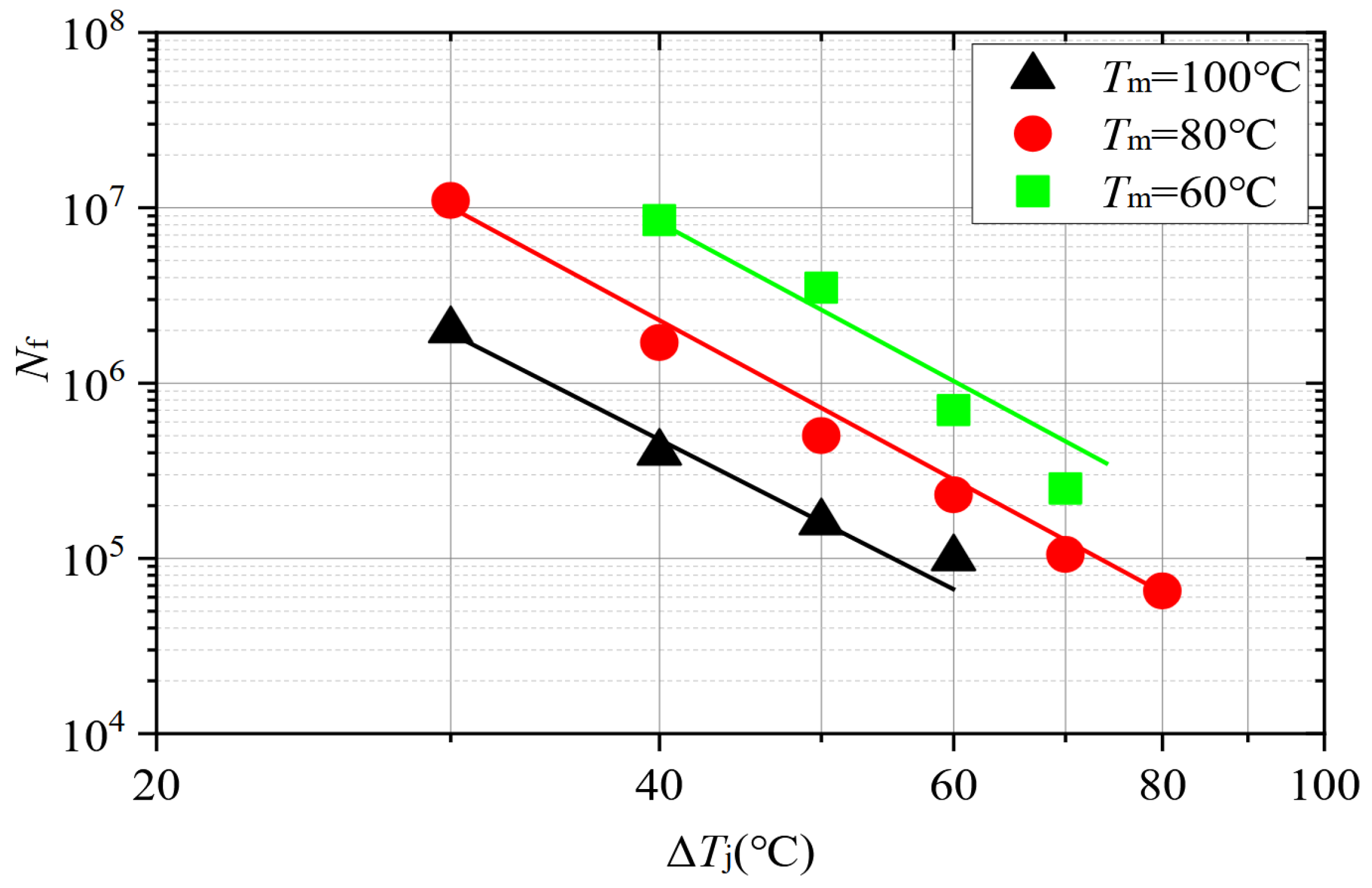
Even if difficult in double-sided modules, obtaining temperatures of MOSFETs during pretests is a must for manufacturers, as shown in Figure 3, for the same average component temperature (80 °C), going from a variation of 40 °C to 50 °C during a cycle leads to a division of the component’s lifetime by 4. Similarly, going from an average temperature of 80 °C to 100 °C, for the same thermal variation of 40 °C, leads to a division of the lifetime by 5. Hence, to determine lifespan, precise acquisition of the junction temperature is needed. If no direct access to the die is possible, only thermally sensitive electrical parameters (TSEPs) or built-in sensors [12] are then suitable.
A major drawback of SiC MOSFETs is the difficulty in manufacturing wafers with limited imperfections, which leads to the need to manufacture smaller dies compared to Si ones to achieve the same die-per-wafer yield [3]. Hence, parallelizing (same gate, drain, and source connections) dies is mandatory for high-current applications. This comes with other problems, such as the risk of current and thermal imbalance between MOSFETs, which can both lead to dysfunction. If one of the MOSFETs is subjected to greater thermal cycling than the others, its reduced lifetime shortens the lifetime of the system as a whole.
Actually, despite its importance, no method allows for detecting thermal imbalance in double-sided modules using totally parallelized dies by TSEPs [13]. Only an apparent temperature is extracted from TSEPs, which does not enable the determination of potential thermal imbalances and overheating dies.
A method has been developed to determine the maximal junction temperature of multi-chip SiC MOSFET single-sided cooling power modules [14], using deep learning and a TSEP, but the process is based on optical-fiber measurement of the surface temperature of dies and cannot be applied to double-sided modules. Studies have characterized the apparent temperature estimated via TSEPs for parallelized dies, showing that certain TSEPs ( V c e , V f ) only allow the estimation of the average temperature of the parallelized dies for low Δ T , while others (turn-off transient or V 0 ) allow the estimation of a temperature between the average temperature of the dies and the maximum one [15,16]. Nevertheless, these articles address Si IGBTs, or Si and SiC diodes, and their validity with regard to SiC MOSFETs is not clear.
Thus, the main objective of this article is to develop an electrical measurement method that determines temperature imbalances between fully parallelized SiC MOSFETs, even when the MOSFETs are not accessible. To this end, TSEPs will be investigated in order to determine what temperature is estimated (average, maximum, minimum, or other). The intended application of this method is the determination of the maximum junction temperature ( T j ) of SiC MOSFETs when no direct measurement of T j is possible, in order to ensure the reliability of double-sided power modules.
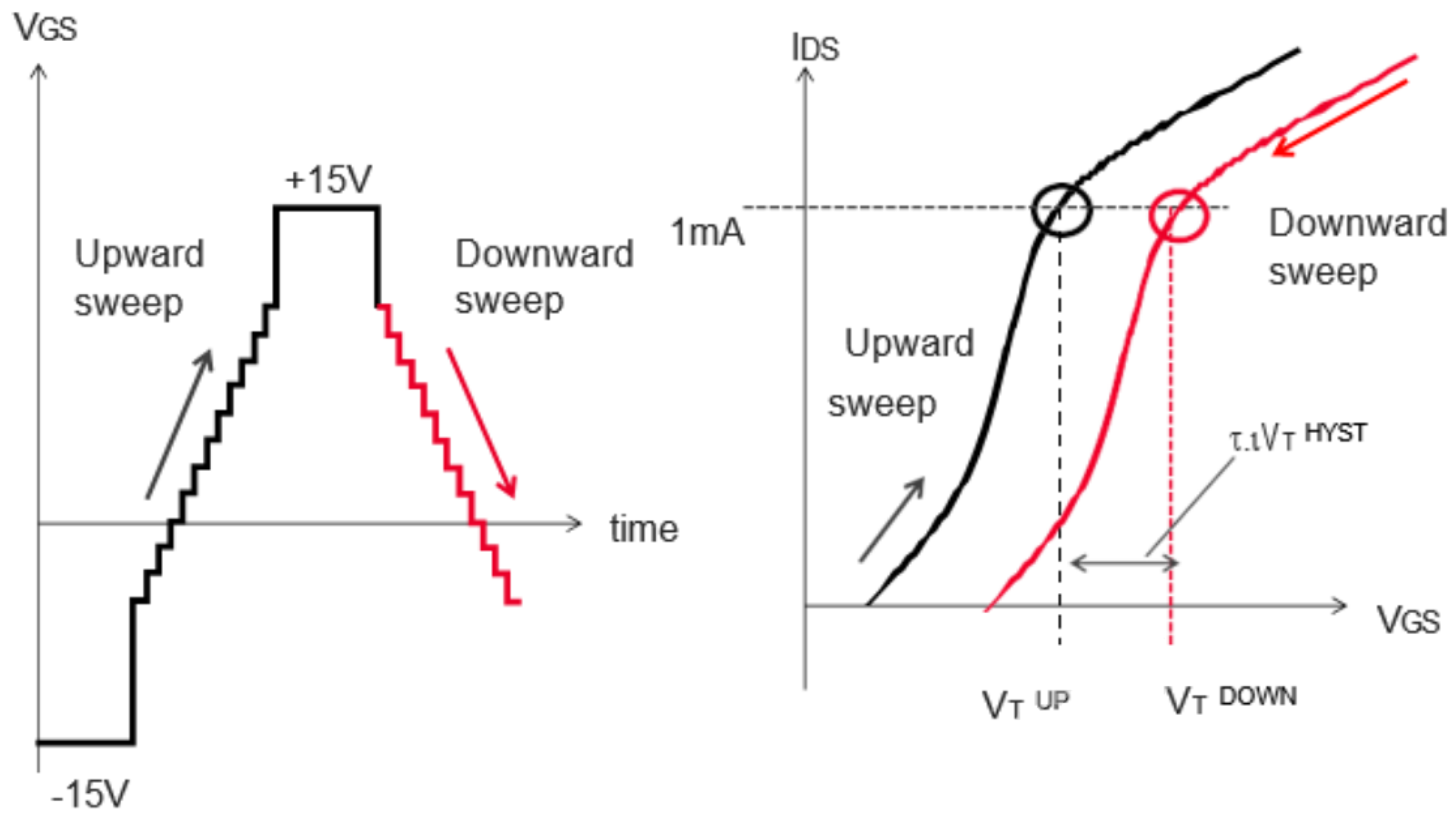
A drawback of using SiC MOSFETs is their V t h shift, which is the subject of discussion among both industry professionals and researchers (see Figure 4). V t h is a key parameter because its instability plays a role in current imbalance during operation and because it is an interesting TSEP. To mitigate the impact of V t h shift after stresses, conditioning methods have been developed [17], such as the JEDEC guidelines [18], which describe circuits allowing precise measurement of V t h . Conditioning is usually achieved by applying a positive or negative voltage at the gate of the MOSFET while short-circuiting its drain and source to remove carrier trapping. Measurement is then performed by short-circuiting the gate and drain and forcing a small current (see Figure 5) through the device. The resulting voltage is V t h . In this work, the current used to measure V t h as a TSEP will be optimized.
The SiC MOSFETs studied during the tests and simulations are the SCT070W120G3-4AG from STMicroelectronics.

2. Methodology

In the first part, simulations are carried out to explore the behavior of the TSEPs when a temperature imbalance occurs between the two MOSFETs. Once the two TSEPs have been described, a test bench is set up to reproduce the simulation conditions on real components. A study of the optimization of the I V t h current is proposed. Simulations and tests are compared. Finally, a measurement method for detecting temperature imbalances in MOSFETs is presented.

2.1. Simulations

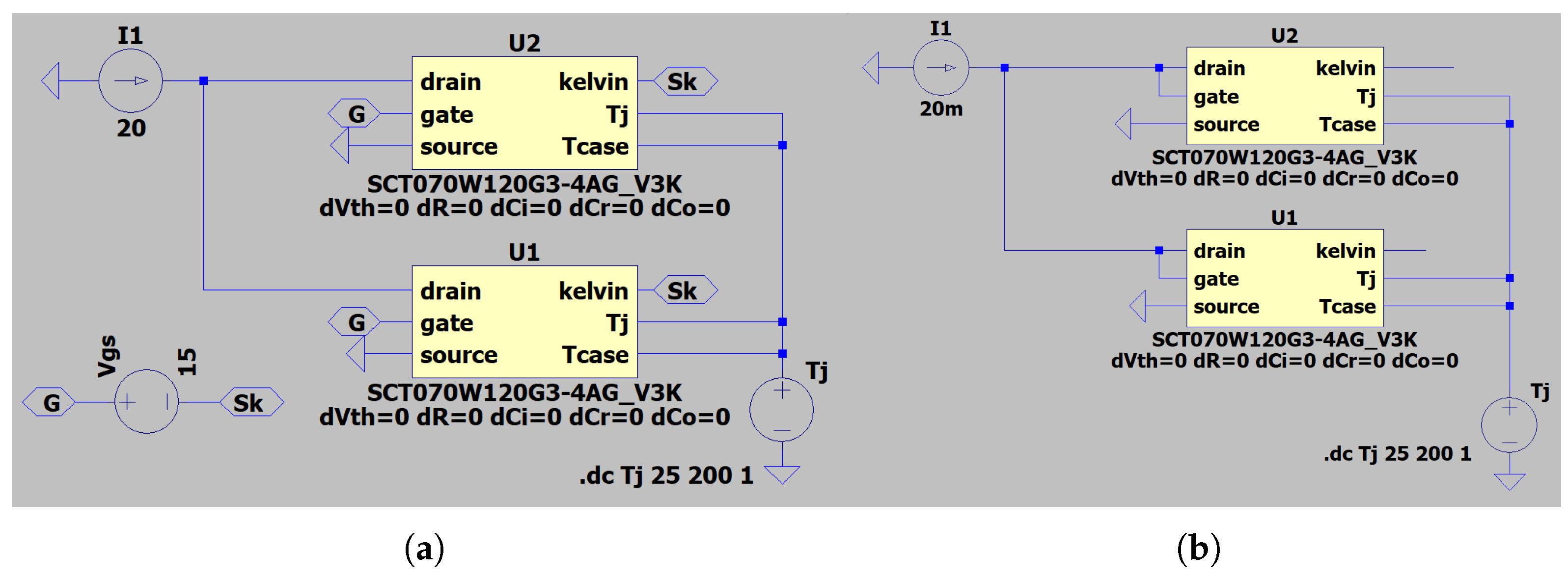
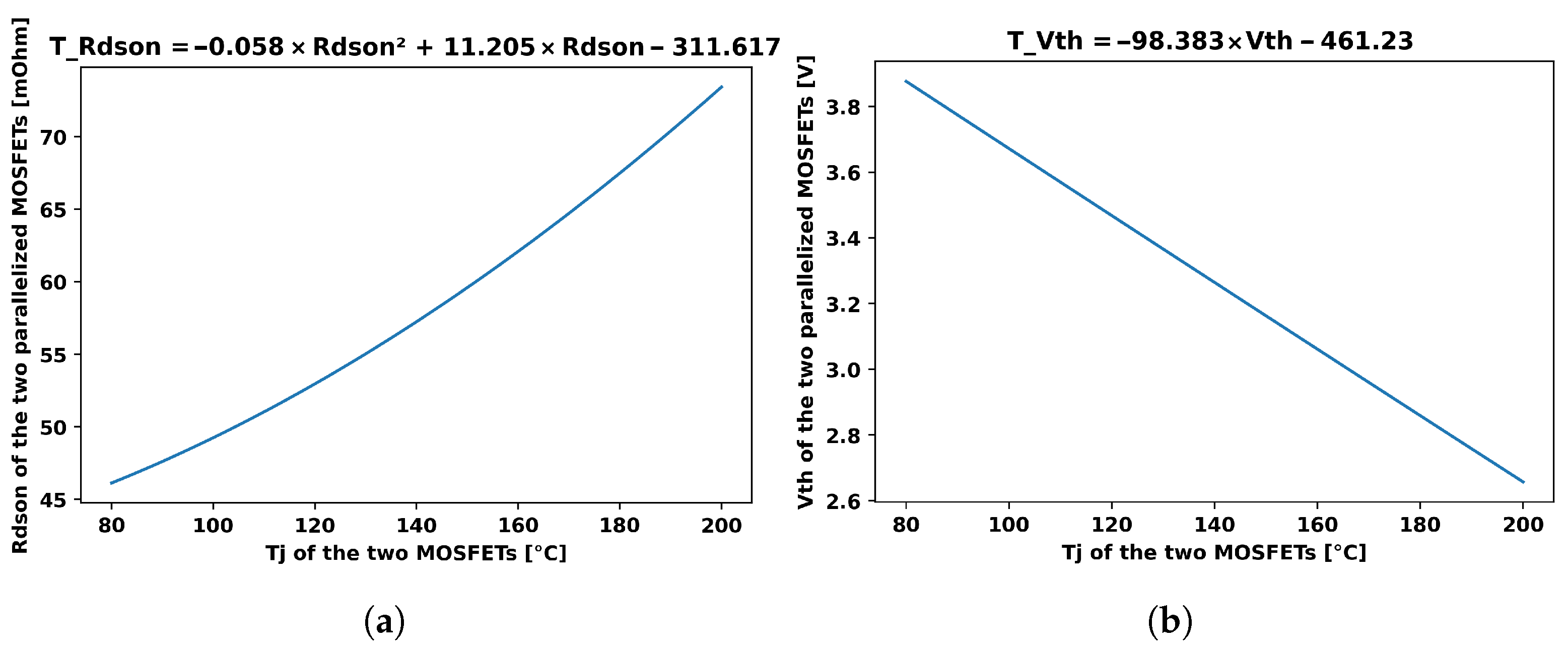
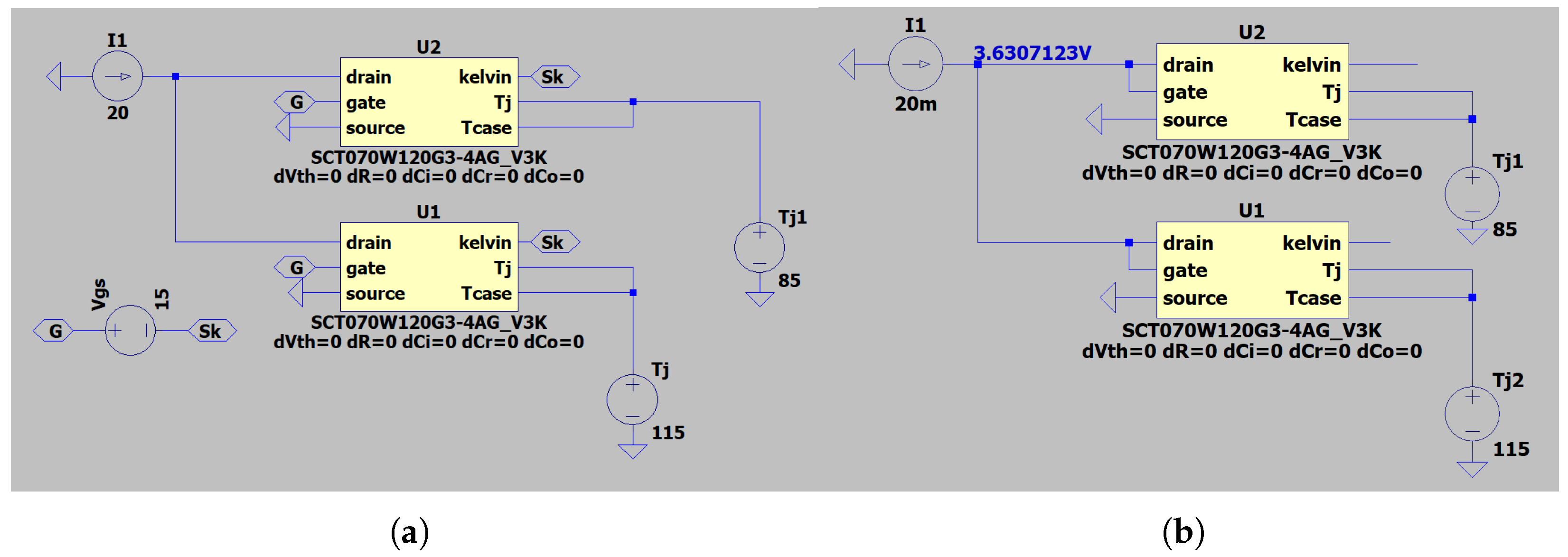
Two well-known TSEPs, the R d s o n [19,20,21] and V t h [22,23], are studied to determine which temperature they provide when there is a temperature imbalance. The simulations are conducted using LTSpice software XVII, and the manufacturer’s models are used for the MOSFETs. In each study, the procedure is as follows: an electrical circuit is set up, allowing the measurement of a specific TSEP. Figure 6 shows the setups for the R d s o n and V t h measurements. In each case, the junction temperature of the two MOSFETs, which is the same, is the variable in the simulation. Hence, by simulating the measurement of the V t h and R d s o n when the junction temperature varies, it is possible to obtain a relationship between those parameters, as presented in Figure 7.
Once these two equations are determined, the simulations are repeated, this time incorporating the temperature imbalances between the two MOSFETs (see Figure 8). The mean temperature of the two MOSFETs is kept constant at 100 °C, with a step of Δ T j of 5 °C until it reaches 30 °C.
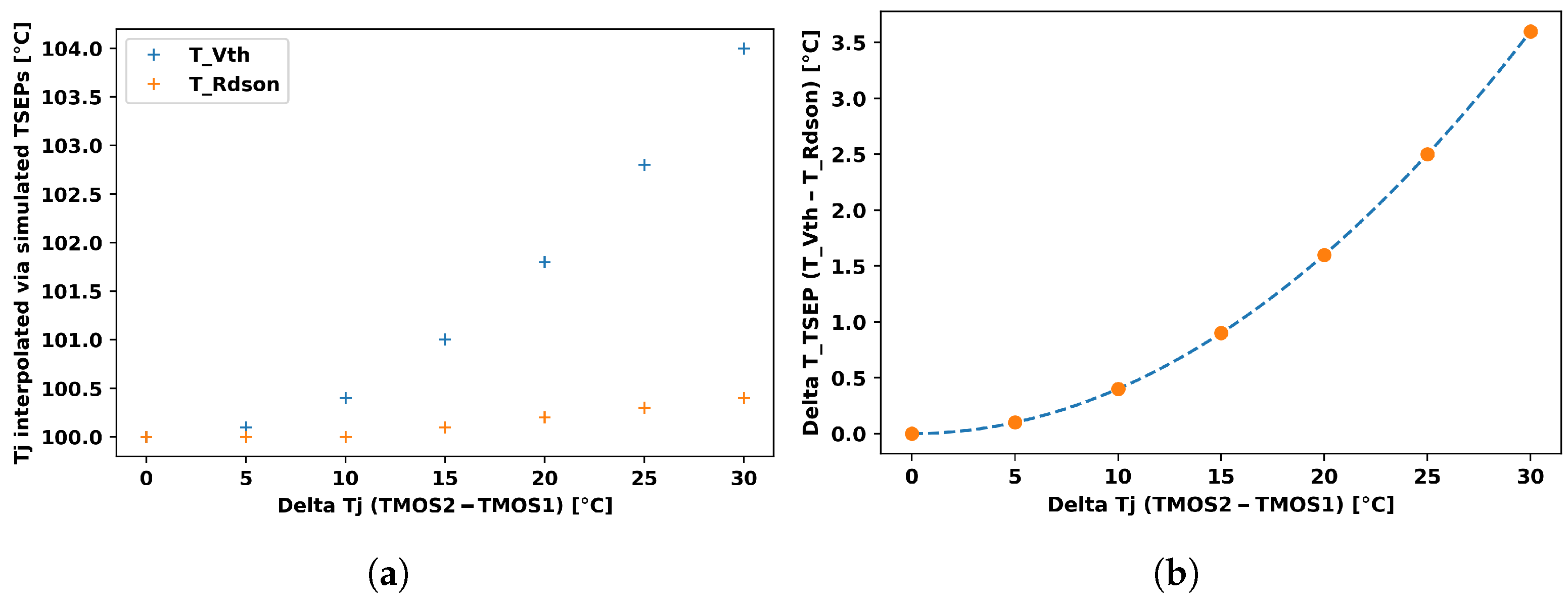
At each point of thermal imbalance, the V t h and R d s o n are simulated. Through the simulations and equations, it is possible to interpolate temperatures via the R d s o n and V t h , named T R d s o n and T V t h . Figure 9a shows the interpolated temperatures via the two TSEPs for different temperature imbalances between the two MOSFETs. It appears that T R d s o n is always very near the average temperature of the two MOSFETs, whereas T V t h seems to be a hybrid of the maximum temperature and the mean temperature (but still closer to the mean one). Then, the difference between the temperatures extrapolated by the V t h and R d s o n (named Δ T T S E P ) is plotted as a function of the thermal imbalance of the two MOSFETs, as shown in Figure 9b. It appears that they are linked by a quadratic law.
With these simulations, it appears that it could be possible to determine the individual temperatures of two MOSFETs that are totally parallelized, when no individual information is obtainable, solely via the measurement of the two TSEPs: the R d s o n would allow the determination of the mean temperature of the devices, and the difference between T R d s o n and T V t h would determine the imbalance.

2.2. Test Bench

The objective of the bench is to perform quick measurements of the R d s o n and V t h , with conditioning before the V t h measurement, to detect thermal imbalance. The time between the V t h measurement and the R d s o n one must be as short as possible to ensure that the same temperature is measured. The test bench (visible in Figure 10) is separated into two parts: fluidic and electric. The tests were conducted on the DepTH-LAB platform [24] at Icam Toulouse.

2.2.1. Fluidic Part

The fluidic part can be seen in Figure 11a. The exposed pad of the MOSFET is in contact with heat sinks via TIMs. Fluids flow through the heat sinks to extract thermal power dissipation and impose the casing temperatures. The thermal resistance of the foils and heat sinks is estimated at 1.5 °C/W. As each heat sink is connected to a different cryostat, each casing temperature can be monitored separately. Flow rates and inlet and outlet temperatures are controlled. In addition, two thermocouples (T-types) are placed under each MOSFET to measure the temperature as close as possible to the Tcase. The two cryostats used are the RP205E from LAUDA (Lauda-Königshofen, Germany) (with P20.275.50 oil) and the Unistat 510 from HUBER (Edison, NJ, USA) (with M20.195/235.20 oil). The oils used allow the liquid temperature (and thus the casing temperature of the MOSFETs) to reach a maximum of 200 °C for high-temperature tests.

2.2.2. Electrical Part

As seen in Figure 11b, the electric part of the bench can be separated into three subparts: current sources and switches (green), 4-state drivers (red), and configuration changes + measurements (conditioning and R d s o n to V t h configuration) (blue).
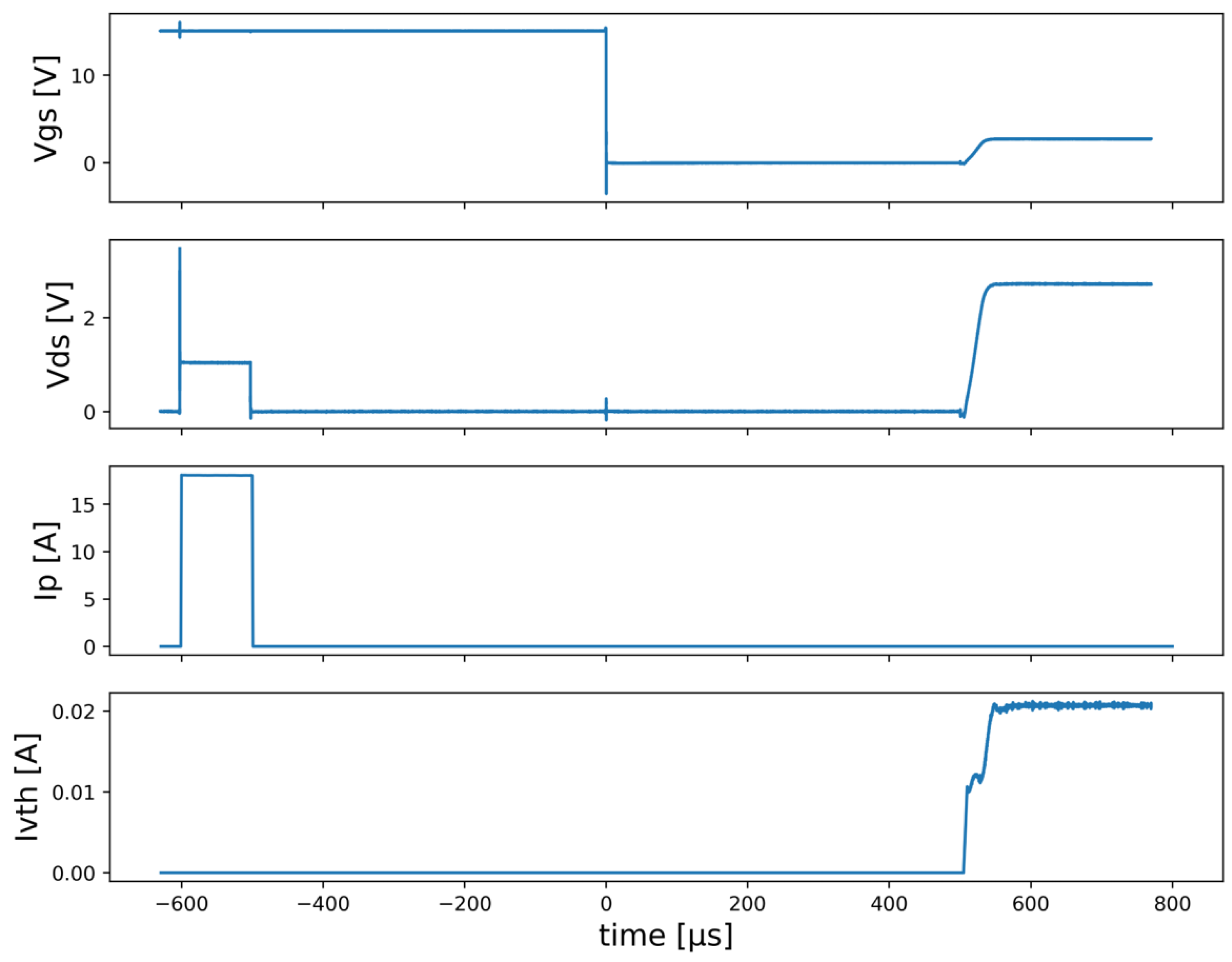
Each test can be split into the following steps, as shown in Figure 12.
During the R d s o n step, a voltage Vgsmax is applied to the gate (15 V). A constant current Id is injected into the drain (typically 10 A per MOSFET). The voltage is measured across the drain and the Kelvin source to obtain Vdsk, and the R d s o n is calculated from the voltage and current. Switch S1 is then opened to cut the current Ip.
During the conditioning step, successive voltages are applied to the gate in order to precondition the MOSFETs and to ensure that the V t h measurements are repeatable. In this study, a voltage of 15 V is applied for 1 s during this phase.
During the V t h step, the gate and drain are short-circuited by closing S3. A small current I V t h is injected into the drain–gate by closing S2. The current flows through the gate first until the charging of the capacitor Cgs closes the channel. When it does, the current flows through the drain, and the voltage stabilizes. Vds can then be measured to obtain the V t h .
Commands for all switches are managed by an Arduino Uno microcontroller (ARDUINO, Monza, Italy) with direct manipulation of the ports to achieve a minimum instruction execution time (time between two switch operations) of 50 ns.
Measurement is performed with an oscilloscope MSO58N of TEKTRONIX (Beaverto, OR, USA). The voltage probe for Vds is a TEKTRONIX TPP0500B, and the power current is measured with a TEKTRONIX TCP0030A current probe. The current I V t h is generated by an SMU (Keithley 2612), and the current Ip is generated by an EA-PS 2042-20B.

3. Results

3.1. Choice of I V t h

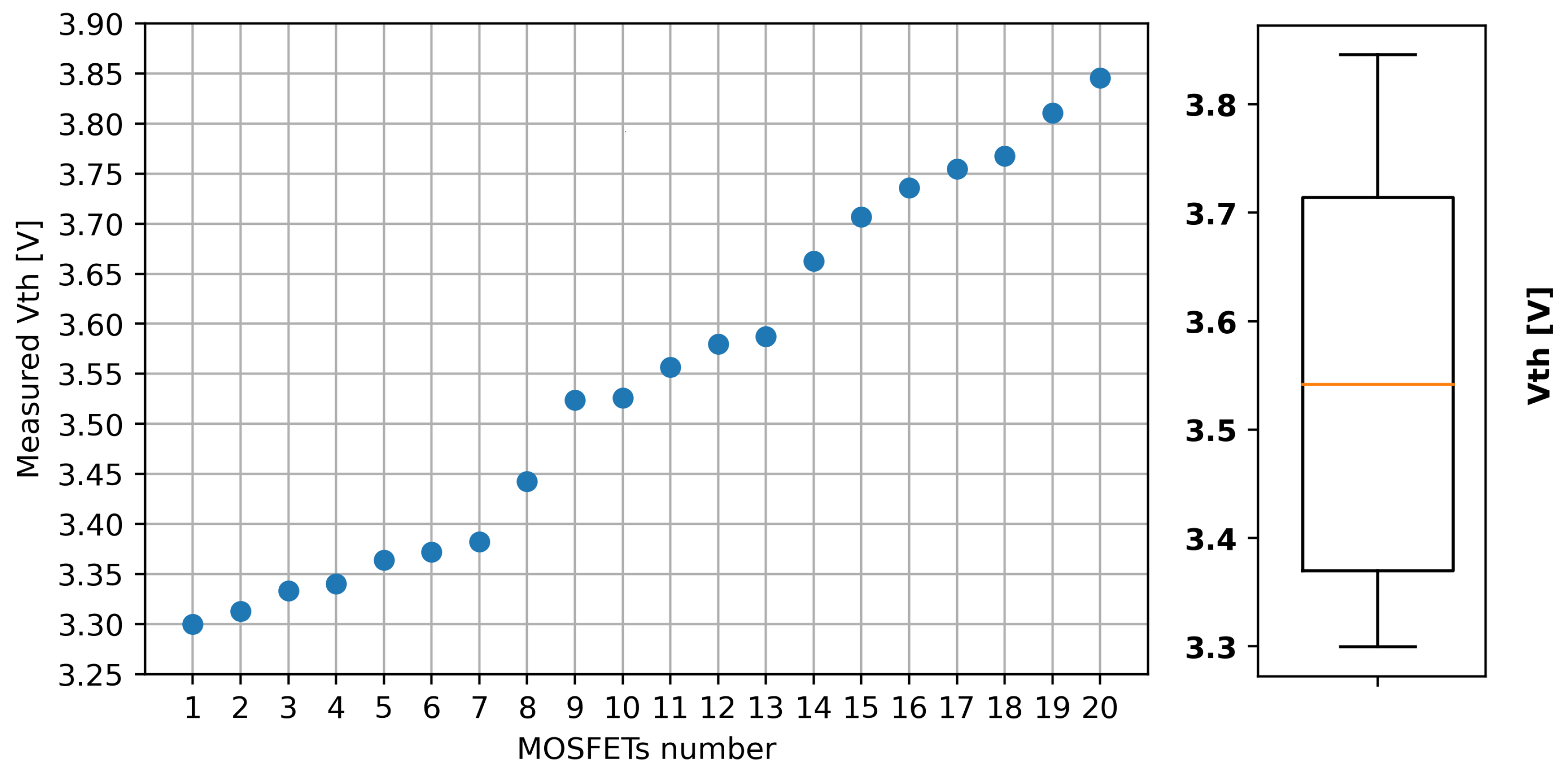
First, all ten SiC MOSFETs had their V t h and R d s o n measured individually (see Figure 13). It was arbitrarily decided to use 10 mA for the V t h current in order to compare the V t h between MOSFETs. Since MOSFETs 9 and 10 were the ones with the best matching V t h (3.524 V and 3.526 V), they were the two MOSFETs chosen to be parallelized.
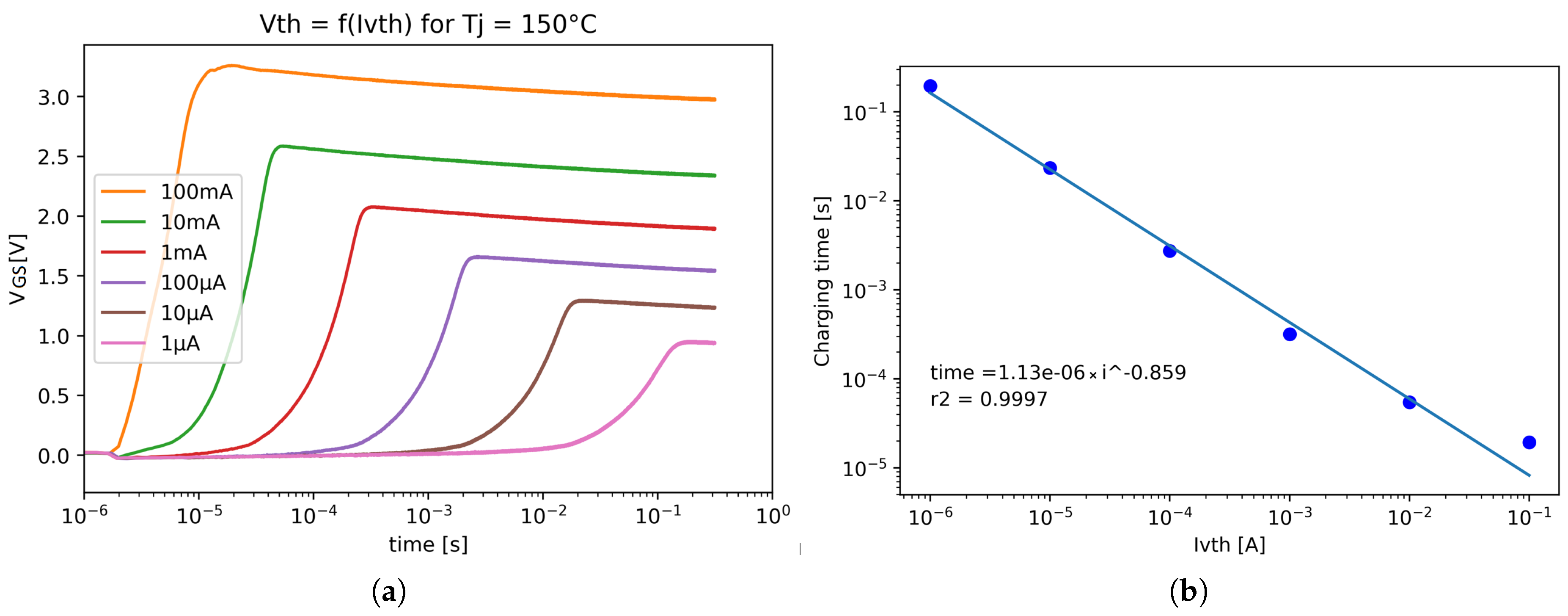
An important parameter in this setup is the choice of the current used to measure the threshold voltage. As it is defined as the minimum voltage to apply to the gate and drain to achieve a certain current in the drain, its value can change depending on the current selected. The JEDEC guidelines do not indicate the values to use; hence, every MOSFET manufacturer uses a different value: 1 mA for STMicroelectronics, 6.4 for Rohm, and 3.3 for INFINEON. As no information on why this current is used was given, neither by the manufacturers nor by JEDEC, a study of the optimal I V t h was proposed. A much wider range of currents was covered than is usual in industry, from 1 µA to 1 ampere, to obtain a proper idea of the ideal value. Each measurement was subjected to a conditioning voltage of 15 V for one second. Each time, the Vth of the two parallelized MOSFETs was measured at the same temperature. As the method used to obtain the V t h relied on the loading of the capacitance Cgs under a constant current to obtain the channel of the MOSFET closed, there was a loading time before the V t h was obtained (see Figure 14a). It appears that the higher the current, the faster the measurement (see Figure 14b). The V t h was considered obtained when the Vgs reached its maximum value.
Having the shortest possible capacitance charging time is extremely important in tests. As the V t h is measured without power injection, the measurement must be taken immediately after an injection. If the loading time is too long, the cooling of the chip during that time will not be negligible, making the measurement and its comparison with the R d s o n irrelevant.
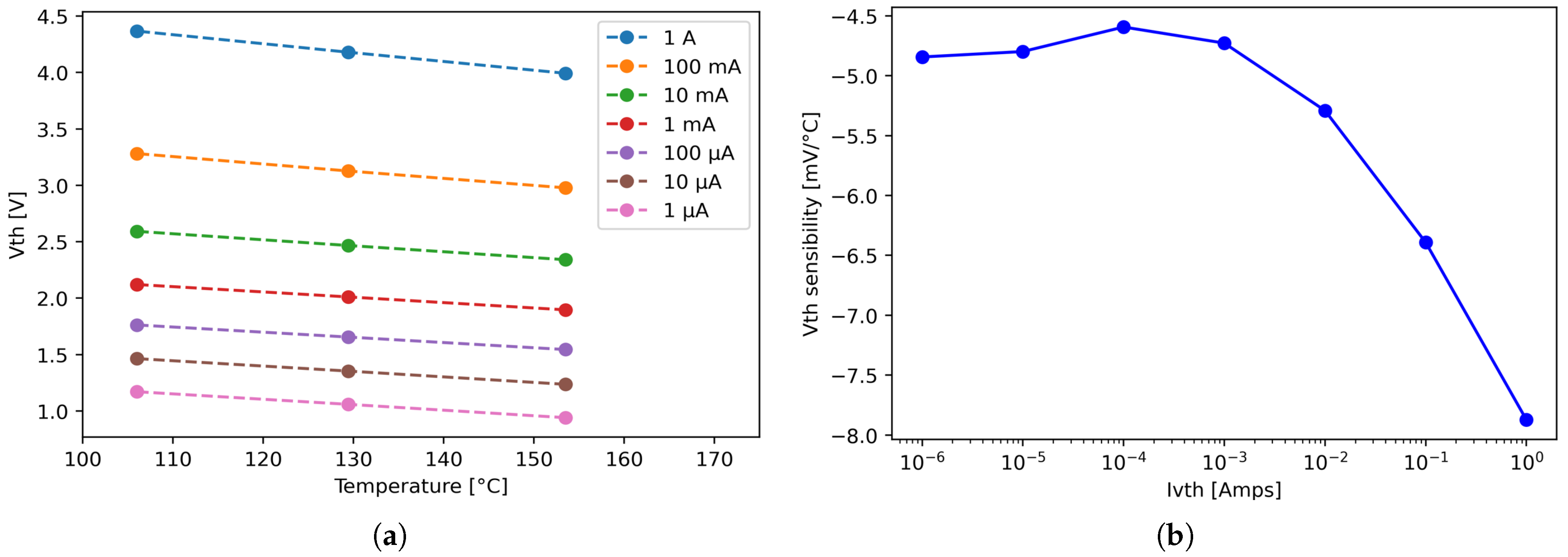
Nonetheless, the charging time of the Vth is not the only parameter to consider. The curves shown in Figure 15a were obtained for three junction temperatures: 105, 130, and 155 °C. Considering that the V t h is linear with temperature, the sensitivity was extracted from each curve shown in Figure 15a and then plotted, as shown in Figure 15b. It seems that the V t h was more sensitive to temperature variations when the current was higher than 1 mA. Below this value, the sensitivity stayed constant at around −4.75 mV/°C.
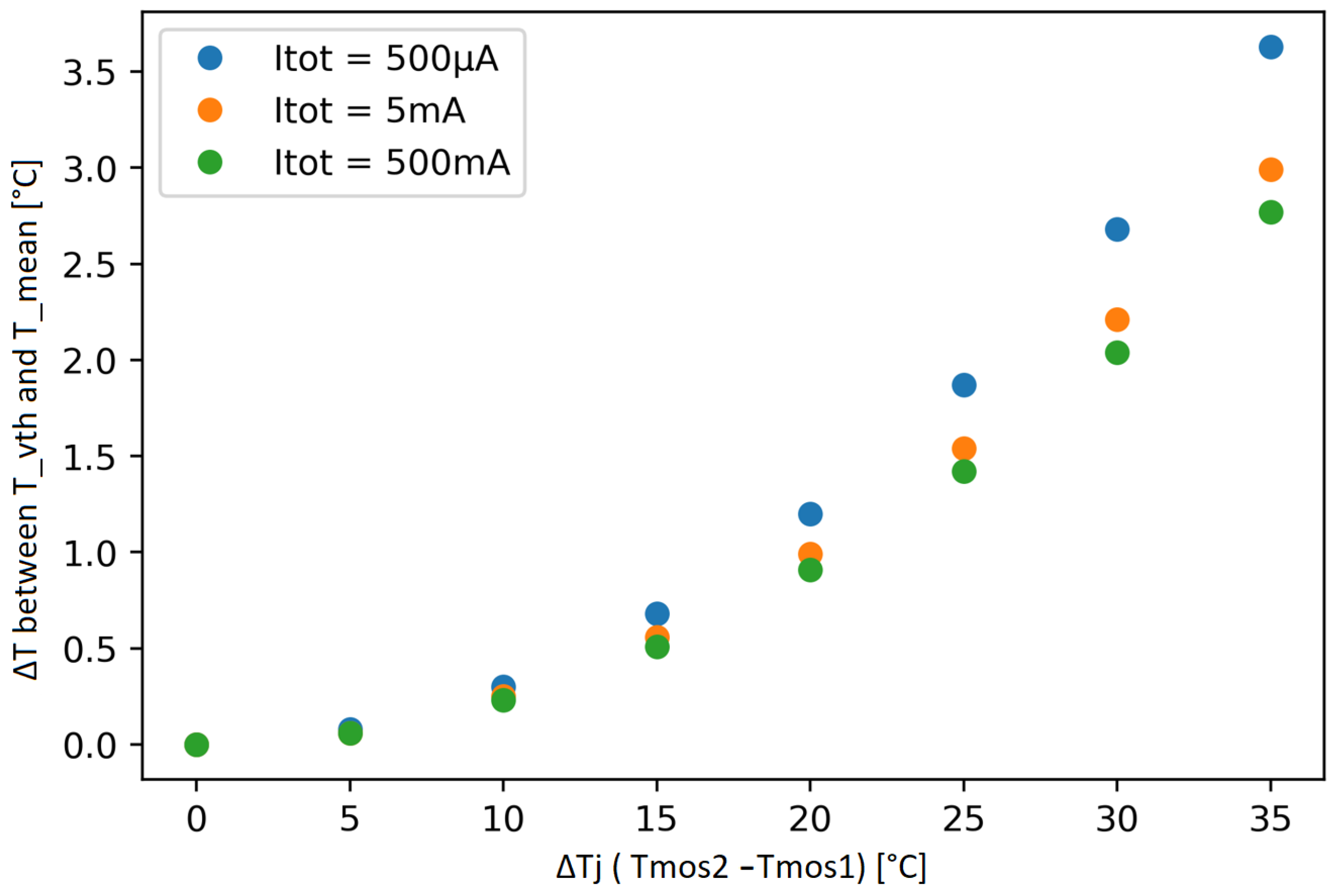
Another important parameter that must be considered when choosing the I V t h is the temperature measured when an imbalance is present. As shown in Figure 16, the current should be as low as possible to obtain good sensitivity to the temperature imbalance between the two MOSFETs.
This last parameter (sensitivity to thermal imbalance) is in direct opposition to the first two (sensitivity to temperature and time to charge Cgs). Hence, a compromise must be found between the measurement accuracy of the temperature imbalance and the measurement speed. For this study, the current selected was 10 mA per MOSFET. With two MOSFETs parallelized, the gate charge time should be only 32 µs, with a sensitivity of 5.5 mV/°C.

3.2. Imbalance Measurement

The first objective was to demonstrate the feasibility of temperature imbalance detection. It was decided to perform long gate saturation to suppress traps and V t h instability before each measurement (1 s).
Figure 17 illustrates the scenario used to measure the R d s o n and V t h successively after a one-second conditioning (+15 V on the gate, 0 V Vds). In these tests, the T j of each MOSFET was considered equal to the temperature of its casing, as there was no noticeable self-heating during the scenario.
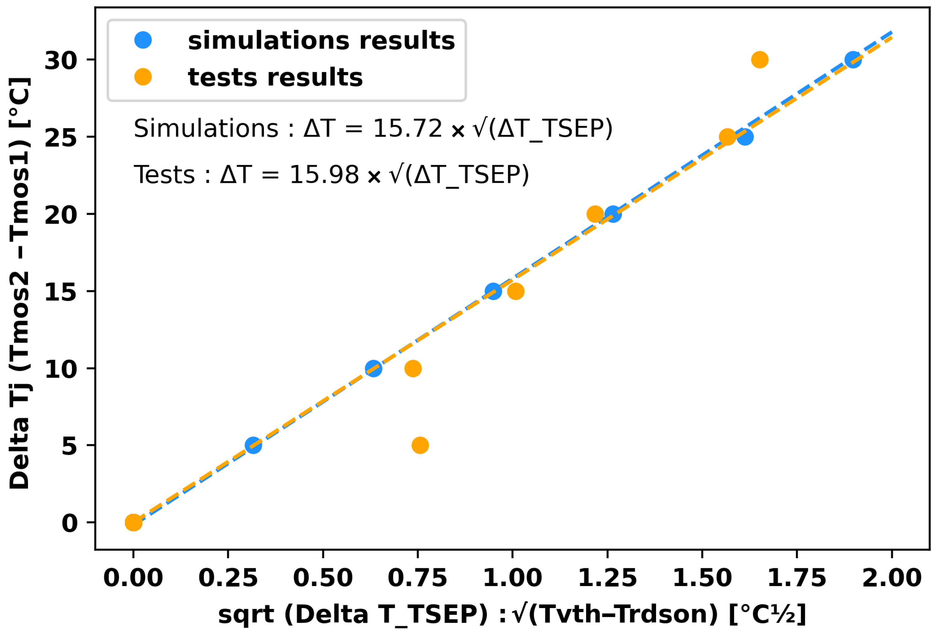
The two MOSFETs were each heated to 100 °C. A test was performed, and then the temperature of one MOSFET was increased to create a thermal imbalance. Measurements were performed, and then the thermal imbalance was increased again. These tests are shown in Figure 18 for the SCT070W120G3-4AG. It can be clearly seen that there is a correlation between the temperature imbalance between the two MOSFETs and the square root of the temperature difference interpolated with the R d s o n and V t h . The simulations and tests show exactly the same sensitivity.
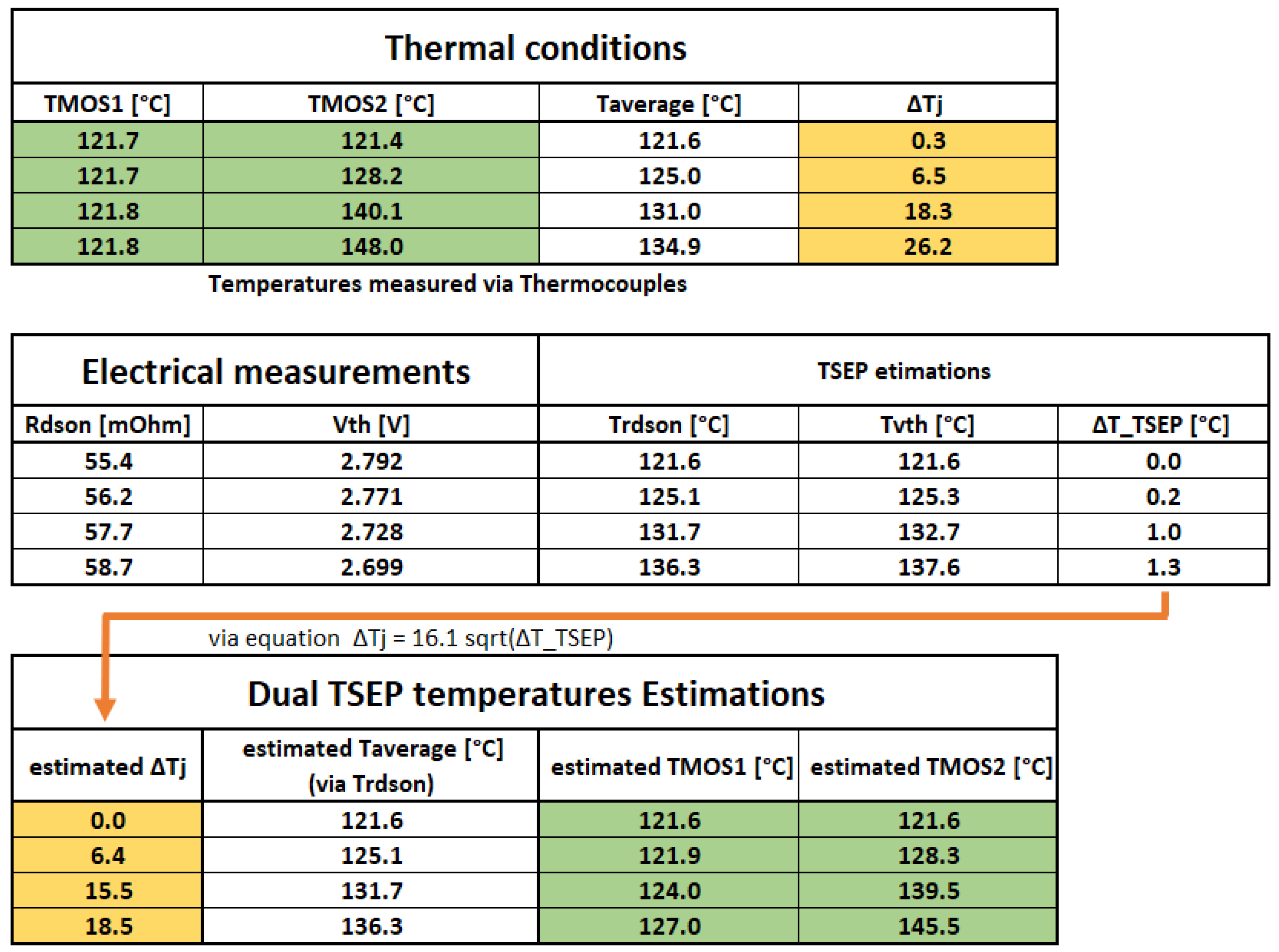
With this correlation, new tests were performed (Figure 19). This time, T1, T2, V t h , and R d s o n were measured. The V t h and R d s o n permitted a T R d s o n and T V t h estimation, and the difference between these two values, using the equation given in Figure 18, made it possible to get an idea of the temperature imbalance between the two MOSFETs. As the temperature interpolated by the R d s o n was near the average temperature of the two MOSFETs, it was then possible to evaluate the individual temperatures of the two MOSFETs, even if totally parallelized.

4. Discussion

The choice of the V t h measurement current, when the drain–gate short-circuit and current-injection method is used, deserves particular attention. In a conventional application, when a single MOSFET is studied, or when imbalance is not an issue, the choice of the V t h should be based on high current values. However, care must be taken to ensure that the power dissipation of the measurement remains negligible or is taken into account. If maximum T j detection is desired, a compromise will have to be found. A value of 10 mA seems to be ideal, as it allows tests to be carried out in a short time while measuring a hybrid temperature between the T m a x and T m e a n .
Simulations and tests show very good similarities. As shown in Figure 18, even if tests are noisy, the two interpolated curves only have a 1.6% difference. This shows that the STMicroelectronics simulation models can be used to determine the thermo-sensitivity and TSEP behavior of several parallelized chips, at least for the R d s o n and V t h simulations.
The SiC results presented are the first of an ongoing test campaign and should be regarded as a work in progress. So far, only offline measurements have been conducted, without accounting for self-heating. The need for optimized conditioning before measurement has not been studied.
Nonetheless, these first results are promising. As shown in Figure 19, it is possible to detect temperature imbalances in simple cases. It should be noted that even if the imbalance is underestimated, it is much more precise than a single measurement of the R d s o n or V t h . New tests must be carried out at different casing temperatures to determine whether the results are reproducible. More importantly, tests with elevated junction temperatures due to self-heating will be performed, as this is the goal of any TSEP.
Assuming that the lifetime of the chips is halved when the junction temperature increases by ten degrees, it can be seen that the new method makes it possible to estimate the lifetime of the chips with far fewer errors. Taking the extreme case, where one MOSFET is at 121 °C and the other at 148 °C, where the actual maximum junction temperature is 148 °C (lifetime normalized at 1), a conventional measurement using a simple TSEP would, at best, have estimated the virtual junction temperature at 138 °C (i.e., a lifetime of 2). Thanks to the method developed, the maximum temperature reached by the MOSFETs was estimated at 145.5 °C (lifetime of 1.2). It appears that the lifetime of the module can then be much more accurately estimated.
Moreover, it should be noted that as the V t h is unstable, even with proper conditioning, only important imbalances of temperature can be estimated, as smaller ones could be caused by natural fluctuations of the V t h . Finally, this entire study was carried out using matched MOSFETs, which have roughly the same V t h at the same temperature. It is likely that MOSFETs with different electrical characteristics would not allow this method to be used. However, the trend in power electronics modules is to couple MOSFETs with equivalent electrical characteristics, which makes it likely that this approach will be valid for new modules. On older modules, the shift in the V t h over time could raise questions about the feasibility of this method. However, this method has been designed to qualify the lifetime of new modules by extracting their maximum T j . Hence, this method should be of interest in this particular niche.
As a preliminary analysis, it is reasonable to assume that temperature imbalances in excess of at least 15 °C will be observable using this method.

5. Conclusions

By comparing the R d s o n and V t h thermal responses of two completely parallelized SiC MOSFETs, this article developed a new non-intrusive method to detect thermal imbalances in power modules where no direct access to dies is available. This method exploits the fact that the interpolated virtual junction temperature via the R d s o n is close to the average temperature of the two components, regardless of the temperature imbalance between them, and the fact that, conversely, the temperature obtained by interpolating the V t h , when MOSFETs are preconditioned, is a hybrid temperature between the average and maximum temperatures of the two components. An empirical relationship was then established between the temperature difference interpolated by the R d s o n and V t h and the temperature difference between the MOSFETs.
Initially, simulations were carried out to determine what temperature each TSEP could interpolate.
A test bench was presented, which enabled the R d s o n and V t h of the parallelized MOSFETs to be measured in rapid succession, as well as allowing different reference temperatures, and therefore different junction temperatures, to be imposed on the components.
The initial tests made it possible to determine an optimal current to ensure that the V t h is sensitive both to global temperature variations and to temperature variations between MOSFETs. To ensure that the gate loading time of the MOSFETs studied was not too long, a compromise was found, enabling the optimal current to be set at 10 mA per parallelized die.
Subsequently, when tests were carried out, it was shown that the expected behavior obtained through simulation corresponded well to that obtained through tests, showing that the manufacturer’s LTSpice models, in the context of the study of the V t h and R d s o n and their sensitivity to temperature, are sufficiently accurate. The sensitivity of the Δ T T S E P is quite small, and even a 1 °C error in the measurement of the temperature of the R d s o n or V t h could lead to significant errors in the estimation of the thermal imbalance. Nevertheless, the first tests carried out show a clear improvement in the maximum junction temperature estimated using the developed method.
Further tests will be carried out to confirm these results. First, these tests will be performed using chips from other manufacturers in order to validate the generalization of this measurement method. In addition, other TSEPs will be tested to determine whether the V t h , which suffers from instability over time, can be replaced. A study on optimizing the voltage and preconditioning time will be carried out to further increase sensitivity to temperature imbalances between MOSFETs. A second version of this bench is currently in production, which will enable new TSEPs to be tested and up to three MOSFETs to be parallelized.

Author Contributions

Conceptualization, L.A.; Investigation, L.A.; Methodology, L.A.; Software, L.A.; Supervision, J.-P.F.; Writing—original draft, L.A.; Writing—review and editing, P.T. and J.-P.F. All authors have read and agreed to the published version of the manuscript.

Funding

This work is part of the COMOSIC Phd project, and has received funding from the Occitanie region, in France.

Data Availability Statement

The raw data supporting the conclusions of this article will be made available by the authors on request.

Acknowledgments

This article is a revised and expanded version of a paper [25], which was presented at THERMINIC, Toulouse, France, 25–27 September 2024.

Conflicts of Interest

The authors declare no conflict of interest.

Abbreviations

The following abbreviations are used in this manuscript:
SiCSilicon Carbide
TSEPThermally sensitive electrical parameter
V t h Threshold voltage
R d s o n On-state resistance
T j Junction temperature
Δ T j T j M O S F E T 2 T j M O S F E T 1
T V t h Temperature estimated via V t h measurement
T R d s o n Temperature estimated via R d s o n measurement
Δ T T S E P T V t h T R d s o n
I V t h Current injected into the drain and gate of the MOSFET to determine its V t h

References

  1. Robles, E.; Matallana, A.; Aretxabaleta, I.; Andreu, J.; Fernández, M.; Martín, J.L. The role of power device technology in the electric vehicle powertrain. Int. J. Energy Res. 2022, 46, 22222–22265. [Google Scholar] [CrossRef]
  2. Liu, G.; Wu, Y.; Li, K.; Wang, Y.; Li, C. Development of high power SiC devices for rail traction power systems. J. Cryst. Growth 2019, 507, 442–452. [Google Scholar] [CrossRef]
  3. Buffolo, M.; Favero, D.; Marcuzzi, A.; De Santi, C.; Meneghesso, G.; Zanoni, E.; Meneghini, M. Review and Outlook on GaN and SiC Power Devices: Industrial State-of-the-Art, Applications, and Perspectives. IEEE Trans. Electron Devices 2024, 71, 1344–1355. [Google Scholar] [CrossRef]
  4. She, X.; Huang, A.Q.; Lucía, Ó.; Ozpineci, B. Review of Silicon Carbide Power Devices and Their Applications. IEEE Trans. Ind. Electron. 2017, 64, 8193–8205. [Google Scholar] [CrossRef]
  5. Schuderer, J.; Vemulapati, U.; Traub, F. Packaging SiC power semiconductors—Challenges, technologies and strategies. In Proceedings of the 2014 IEEE Workshop on Wide Bandgap Power Devices and Applications, Knoxville, TN, USA, 13–15 October 2014; pp. 18–23. [Google Scholar] [CrossRef]
  6. Ji, S.; Zhang, Z.; Wang, F. Overview of high voltage sic power semiconductor devices: Development and application. CES Trans. Electr. Mach. Syst. 2017, 1, 254–264. [Google Scholar] [CrossRef]
  7. Marie, A.; Cougo, B.; Renaudie, L.; Koladoum, T.K.; Fradin, J.P. Precise 3D modelling of SiC die temperature oscillation for lifetime prediction of power modules used in DC/AC power converters. In Proceedings of the 2024 30th International Workshop on Thermal Investigations of ICs and Systems (THERMINIC), Toulouse, France, 25–27 September 2024; pp. 1–6. [Google Scholar] [CrossRef]
  8. Lee, H.; Smet, V.; Tummala, R. A Review of SiC Power Module Packaging Technologies: Challenges, Advances, and Emerging Issues. IEEE J. Emerg. Sel. Top. Power Electron. 2020, 8, 239–255. [Google Scholar] [CrossRef]
  9. Liu, M.; Coppola, A.; Alvi, M.; Anwar, M. Comprehensive Review and State of Development of Double-Sided Cooled Package Technology for Automotive Power Modules. IEEE Open J. Power Electron. 2022, 3, 271–289. [Google Scholar] [CrossRef]
  10. Yan, Y.; Chen, C.; Wu, Z.; Guan, J.; Lv, J.; Kang, Y. A High Power Density Double-Side-End Double-Sided Bonding SiC Half-Bridge Power Module. IEEE Trans. Transp. Electrif. 2023, 9, 3149–3163. [Google Scholar] [CrossRef]
  11. Paul, R.; Alizadeh, R.; Li, X.; Chen, H.; Wang, Y.; Mantooth, H.A. A Double-Sided Cooled SiC MOSFET Power Module for EV Inverters. IEEE Trans. Power Electron. 2024, 39, 11047–11059. [Google Scholar] [CrossRef]
  12. Kim, M.K.; Yoon, S.W. Novel built-in sensor for in-situ monitoring of temperature and thermal stress in power modules. In Proceedings of the 2015 IEEE Energy Conversion Congress and Exposition (ECCE), Montreal, QC, Canada, 20–24 September 2015; pp. 4513–4519. [Google Scholar] [CrossRef]
  13. Li, H.; Zhao, S.; Wang, X.; Ding, L.; Mantooth, H.A. Parallel Connection of Silicon Carbide MOSFETs—Challenges, Mechanism, and Solutions. IEEE Trans. Power Electron. 2023, 38, 9731–9749. [Google Scholar] [CrossRef]
  14. Kim, M.K.; Yoon, Y.D.; Yoon, S.W. Actual Maximum Junction Temperature Estimation Process of Multichip SiC MOSFET Power Modules With New Calibration Method and Deep Learning. IEEE J. Emerg. Sel. Top. Power Electron. 2023, 11, 5602–5612. [Google Scholar] [CrossRef]
  15. Gonzalez, J.O.; Alatise, O.; Ran, L.; Mawby, P. Impact of Temperature Imbalance on Junction Temperature Identification for Multiple Chip Modules Using TSEPs. In Proceedings of the PCIM Europe 2017; International Exhibition and Conference for Power Electronics, Intelligent Motion, Renewable Energy and Energy Management, Nuremberg, Germany, 16–18 May 2017; pp. 1–8. [Google Scholar]
  16. Dupont, L.; Avenas, Y. Preliminary Evaluation of Thermo-Sensitive Electrical Parameters Based on the Forward Voltage for Online Chip Temperature Measurements of IGBT Devices. IEEE Trans. Ind. Appl. 2015, 51, 4688–4698. [Google Scholar] [CrossRef]
  17. Peters, D.; Aichinger, T.; Basler, T.; Rescher, G.; Puschkarsky, K.; Reisinger, H. Investigation of threshold voltage stability of SiC MOSFETs. In Proceedings of the 2018 IEEE 30th International Symposium on Power Semiconductor Devices and ICs (ISPSD), Chicago, IL, USA, 13–17 May 2018; pp. 40–43. [Google Scholar] [CrossRef]
  18. JEDEC. JEP183A: Guidelines for Measuring the Threshold Voltage (VT) of SiC MOSFETs. 2023. Available online: https://www.jedec.org/standards-documents/docs/jep183a (accessed on 1 June 2025).
  19. Soldati, A.; Menozzi, R.; Concari, C. In-circuit Shoot-through-based Characterization of SiC MOSFET TSEP Curves for Junction Temperature Estimation. In Proceedings of the 2020 IEEE Energy Conversion Congress and Exposition (ECCE), Detroit, MI, USA, 11–15 October 2020; pp. 2850–2857. [Google Scholar] [CrossRef]
  20. Zhang, L.; Liu, P.; Guo, S.; Huang, A.Q. Comparative study of temperature sensitive electrical parameters (TSEP) of Si, SiC and GaN power devices. In Proceedings of the 2016 IEEE 4th Workshop on Wide Bandgap Power Devices and Applications (WiPDA), Fayetteville, AK, USA, 7–9 November 2016; pp. 302–307. [Google Scholar] [CrossRef]
  21. Stella, F.; Pellegrino, G.; Armando, E.; Daprà, D. Online Junction Temperature Estimation of SiC Power MOSFETs Through On-State Voltage Mapping. IEEE Trans. Ind. Appl. 2018, 54, 3453–3462. [Google Scholar] [CrossRef]
  22. Li, L.; Ning, P.; Zhang, D.; Wen, X. An exploration of thermo-sensitive electrical parameters to estimate the junction temperature of silicon carbide mosfet. In Proceedings of the 2017 IEEE Transportation Electrification Conference and Expo, Asia-Pacific (ITEC Asia-Pacific), Harbin, China, 2–5 August 2017; pp. 1–5. [Google Scholar] [CrossRef]
  23. Griffo, A.; Wang, J.; Colombage, K.; Kamel, T. Real-Time Measurement of Temperature Sensitive Electrical Parameters in SiC Power MOSFETs. IEEE Trans. Ind. Electron. 2018, 65, 2663–2671. [Google Scholar] [CrossRef]
  24. Icam. DEPth-Lab Platform Presentation. 2022. Available online: https://en.icam.fr/research/depth-lab/ (accessed on 1 June 2025).
  25. Louis, A.; Patrick, T.; Jean-Pierre, F. Sensorless Dual TSEP Implementation for Junction Temperature Measurement in Parallelized SiC Mosfets. In Proceedings of the 2024 30th International Workshop on Thermal Investigations of ICs and Systems (THERMINIC), Toulouse, France, 25–27 September 2024; pp. 1–4. [Google Scholar] [CrossRef]
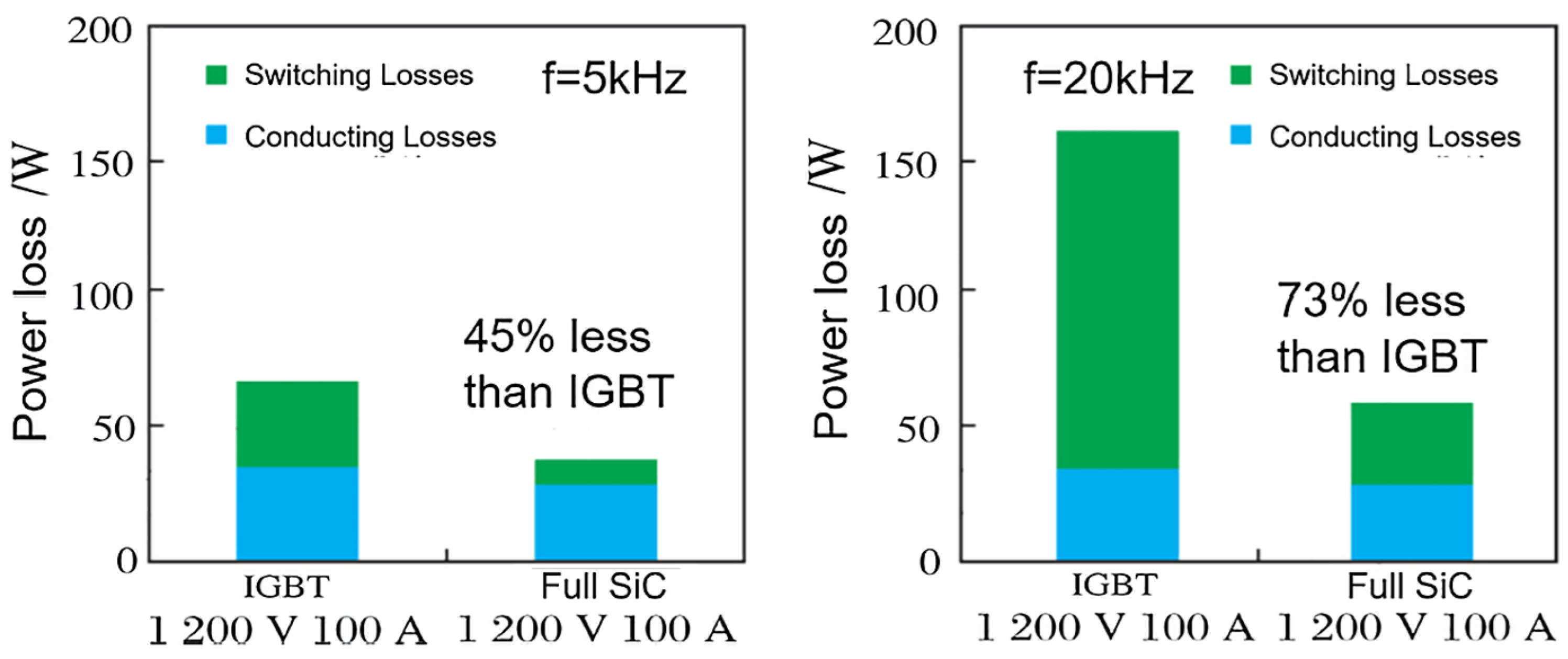
Figure 1. Power loss reduction in a 1200 V/100 A power module when replacing Si IGBTs with SiC MOSFETs [2].
Energies 18 03470 g001
Figure 2. Comparison of single- and double-sided cooling modules [11].
Energies 18 03470 g002
Figure 3. Coffin–Manson law adapted to SiC MOSFETs [13]. Here, Δ T j is the temperature variation of the MOSFET during power cycling, and T m is its average temperature.
Energies 18 03470 g003
Figure 4. V t h shift after stress is applied to the gate [18].
Energies 18 03470 g004
Figure 5. JEDEC conditioning and V t h measurement method [18].
Energies 18 03470 g005
Figure 6. LTSpice simulations used to extract R d s o n = f(T) (a) and V t h = f(T) (b).
Energies 18 03470 g006
Figure 7. Simulated correspondence between R d s o n and T j (a) and between V t h and T j (b), resulting from Figure 6.
Energies 18 03470 g007
Figure 8. LTSpice simulations used to obtain R d s o n (a) and V t h (b) when a thermal imbalance occurs (here, Δ T j = 30 °C).
Energies 18 03470 g008
Figure 9. Temperatures interpolated by simulated TSEPs (via the equations in Figure 7) for different thermal imbalances (a), and the difference between the temperatures interpolated by the V t h and R d s o n as a function of the thermal imbalance (b).
Energies 18 03470 g009
Figure 10. The test bench without installation on heat sinks (left), and MOSFETs on heat sinks (right).
Energies 18 03470 g010
Figure 11. Fluidic part of the bench (a) and simplified command part (b).
Energies 18 03470 g011
Figure 12. Temporal steps of the electric part of the bench.
Energies 18 03470 g012
Figure 13. V t h dispersion across twenty MOSFETs tested, and its box plot.
Energies 18 03470 g013
Figure 14. Vgs curves for different currents as a function of time during a V t h measurement (a), and extracted charging time of Cgs as a function of I V t h (b).
Energies 18 03470 g014
Figure 15. Measured V t h for different I V t h and temperatures (a), and extracted thermal sensitivity of V t h = f( I V t h ) (b).
Energies 18 03470 g015
Figure 16. Difference between the extrapolated temperature of the two parallelized MOSFETs via V t h and their mean temperature as a function of the temperature imbalance of the two MOSFETs for multiple I V t h . MOSFET temperatures are obtained via thermocouples. The mean temperature is kept constant at 100 °C.
Energies 18 03470 g016
Figure 17. Typical scenario for R d s o n / V t h T j comparison.
Energies 18 03470 g017
Figure 18. Relationship between the square root of the imbalance of virtual T j measured with R d s o n and V t h and the imbalance between MOSFET1 and MOSFET2, compared with the LTSpice simulation.
Energies 18 03470 g018
Figure 19. Summary of electrical and thermal measurements made during the series of tests: the virtual T j estimated by each TSEP; the Δ T j estimated by the developed method; and the individual T j values.
Energies 18 03470 g019
Disclaimer/Publisher’s Note: The statements, opinions and data contained in all publications are solely those of the individual author(s) and contributor(s) and not of MDPI and/or the editor(s). MDPI and/or the editor(s) disclaim responsibility for any injury to people or property resulting from any ideas, methods, instructions or products referred to in the content.