Article

Application of Repetitive Control to Grid-Forming Converters in Centralized AC Microgrids †

by
Hélio Marcos André Antunes
1,*,‡,
Ramon Ravani Del Piero
1,‡ and
Sidelmo Magalhães Silva
2,‡
1
Graduate Program in Electrical Engineering, Federal University of Espirito Santo, Av. Fernando Ferrari, 514, Vitória 29075-910, ES, Brazil
2
Graduate Program in Electrical Engineering, Federal University of Minas Gerais, Belo Horizonte 31270-901, MG, Brazil
*
Author to whom correspondence should be addressed.
This paper is an extended version of our paper published in 2017 IEEE 8th International Symposium on Power Electronics for Distributed Generation Systems (PEDG). IEEE, 2017, pp. 1–8,513.
These authors contributed equally to this work.
Energies 2025, 18(13), 3427; https://doi.org/10.3390/en18133427
Submission received: 5 April 2025 / Revised: 15 May 2025 / Accepted: 21 May 2025 / Published: 30 June 2025
(This article belongs to the Special Issue Energy, Electrical and Power Engineering: 4th Edition)

Abstract

The electrical grid is undergoing increasing integration of decentralized power sources connected to the low-voltage network. In this context, the concept of a microgrid has emerged as a system comprising small-scale energy sources, loads, and storage devices, coordinated to operate as a single controllable entity capable of functioning in either grid-connected or islanded mode. The microgrid may be organized in a centralized configuration, such as a master-slave scheme, wherein the centralized converter, i.e., the grid-forming converter (GFC), plays a pivotal role in ensuring system stability and control. This paper introduces a plug-in repetitive controller (RC) strategy tuned to even harmonic orders for application in a three-phase GFC, diverging from the conventional approach that focuses on odd harmonics. The proposed control is designed within a synchronous reference frame and is targeted at centralized AC microgrids, particularly during islanded operation. Simulation results are presented to assess the microgrid’s power flow and power quality, thereby evaluating the performance of the GFC. Additionally, the proposed control was implemented on a Texas Instruments TMS320F28335 digital signal processor and validated through hardware-in-the-loop (HIL) simulation using the Typhoon HIL 600 platform, considering multiple scenarios with both linear and nonlinear loads. The main results highlight that the RC improves voltage regulation, mitigates harmonic distortion, and increases power delivery capability, thus validating its effectiveness for GFC operation.

1. Introduction

The global electric power sector is undergoing significant transformations in both generation and consumption paradigms. Traditionally, power systems were designed to transmit large quantities of energy from centralized power plants located far from load centers. However, the rise of distributed generation is redefining this model, driven by the increasing penetration of renewable energy sources and the shift toward localized energy production situated closer to end users [1,2,3].
In this context, a novel concept has emerged alongside the evolution of distributed generation: the microgrid. A microgrid is a system comprising electrical microsources, loads, and energy storage elements, all controlled as a single dispatchable unit capable of operating either in grid-connected mode or autonomously in islanded mode. These microsources are frequently powered by renewable energy. Moreover, the distributed units within a microgrid can be categorized into three groups based on their control capabilities: (1) grid-feeding converter (GFEC), (2) grid-forming converter (GFC), and (3) grid-supporting converter (GSC) [4,5].
The GFEC can also inject reactive power into the grid, and operates as a current source in PQ mode. The GFC, in contrast, functions as a voltage source in V-f mode, primarily serving loads [6,7]. Lastly, the GSC not only injects active power but also manages reactive power flow and provides ancillary services, such as voltage and frequency regulation, harmonic compensation, and low-voltage ride-through [8]. Importantly, the GSC can be configured to operate as a current or voltage source, depending on the design of its control scheme.
The advancement of power electronics has enabled the development of grid-interactive interfaces that integrate renewable energy sources into utility networks, thereby supporting the autonomous operation of microgrids. When a microgrid is connected to the main utility grid, the voltage and frequency are imposed by the grid, and the GFC operates in PQ mode as a current source, injecting active and reactive power according to system demands. In this operating condition, the GFC can also provide ancillary services, similarly to a GSC [8,9].
In microgrids employing decentralized primary control architectures, GFC strategies have primarily focused on enhancing transient stability, voltage regulation, and load-sharing performance. Commonly, GFCs are controlled using the following approaches: (i) Droop control enables active and reactive power sharing among parallel inverters, although it may exhibit limited dynamic performance; (ii) Virtual Synchronous Machine (VSM) methods, which emulate the inertia and damping of synchronous machines, thereby improving stability margins during faults and sudden load variations [10]; and (iii) Hybrid droop–VSM schemes, which integrate classical droop control with adaptive virtual inertia loops to mitigate frequency deviations during transient events [11].
Despite their widespread adoption, these classical strategies applied to decentralized microgrids exhibit limitations. Emerging approaches have therefore been developed to address these drawbacks. Recent studies have explored:
  • Model Predictive Control (MPC) applied to GFCs, which guarantees optimal reference tracking while respecting the converter’s current and voltage constraints [12];
  • Distributed coordination schemes that eliminate the need for a central communication infrastructure, ensuring resilient voltage restoration and load sharing [13];
  • Machine-learning-based adaptive control techniques, capable of dynamically adjusting virtual inertia and droop parameters in response to varying grid conditions [14];
  • Dynamic virtual-impedance loops, which enhance stability margins in low-inertia scenarios and suppress high-frequency disturbances [15].
In centralized microgrids with a master-slave architecture, the GFC plays a key role in regulating voltage and frequency in island mode. Upon a grid outage or intentional islanding, the GFC transitions to voltage–frequency (V–f) mode, assuming control authority and ensuring seamless disconnection through the opening of the microgrid static switch (MG-SS). To maintain stable operation during and after the transition, the GFC must be interfaced with an energy storage system (ESS), enabling fast dynamic response and continuity of service. This transition must occur without introducing voltage or frequency transients, thus preserving power quality and system stability [9,16,17].
In V-f mode, the GFC must emulate the behavior of a voltage source by generating sinusoidal output voltage with constant amplitude and frequency, even under unbalanced and nonlinear load conditions. Its operating principle is closely related to that of an uninterruptible power supply (UPS), which also integrates an ESS and is designed to independently supply loads with low harmonic distortion. In fact, the IEC 62040-3 standard for UPSs establishes that the total harmonic distortion of voltage (THDv) for cyclic loads must not exceed 8% [18,19]. Analogously, the GFC must ensure high power quality, continuity of service, and voltage stability in microgrids, even in the presence of distributed generators with intermittent behavior [4,20,21].
Figure 1 presents a typical control diagram for a voltage source inverter (VSI) operating as a GFC in V-f mode. This diagram is applicable to both single-phase and three-phase topologies. The VSI is connected to a passive LC filter, ensuring a sinusoidal voltage at its output, reducing harmonics, and enhancing the power quality delivered to the load. To enable the islanded operation of the microgrid, an ESS is integrated into the DC bus, ensuring power supply even in the absence of photovoltaic generation [22]. The VSI operates in a closed-loop configuration, where the voltage loop generates a reference for the inner current loop. In addition, a feedforward action can be implemented to eliminate cross-coupling effects and to improve the dynamic response of the converter [23].
When the control of the GFC consists of both voltage and current loops, the system is defined as having a multi-loop control structure. It is also possible to regulate the output voltage of the GFC using only a voltage loop, in a structure known as single-loop control. However, using only the voltage loop results in the loss of short-circuit protection at the inverter output, and it becomes necessary to implement either active or passive damping techniques to mitigate the issue of harmonic amplification in the LC filter [24,25].
The controllers for the voltage and current loops applied to the GFC are based on different reference frames. In the literature, it is possible to find the following reference frames:
  • Natural reference frame (abc);
  • Synchronous reference frame (dq0);
  • Stationary reference frame ( α β 0).
In [26], a classification of voltage and current controllers applied to the voltage and current loops is presented and illustrated in Figure 2a,b.
In centralized AC microgrids, it is very common to find three-phase GFC controlled in dq0 coordinates. This system uses a proportional-integral (PI) controller for the voltage and current loops, since the fundamental voltage has a DC level. However, this control structure cannot effectively reject disturbances caused by unbalanced loads or distortions due to nonlinear loads [22,27,28]. Also, GFC control can be controlled using Robust and adaptive control methods, such as H and real-time LQR, adjusting controller gains in the face of system uncertainties and grid disturbances [29].
In [30], a GFC controlled by a PI-resonant controller in dq0 coordinates is presented. The converter operates in a single synchronous reference frame (SRF) to address both voltage imbalance and harmonic compensation. Moreover, the virtual impedance loop is adjusted to enhance the overall performance of the compensation.
When adopting GFC control in an AC reference frame, a PI controller does not provide satisfactory performance, since it does not guarantee zero steady-state error in the presence of periodic references [31]. The repetitive controller (RC) offers precise tracking of periodic disturbances and ensures high power quality under unbalanced and nonlinear load conditions [32].
In most existing studies, RC has been applied to suppress odd-order harmonics, which are dominant in the output of inverters feeding nonlinear loads [33,34,35]. Traditional implementations of RC for GFCs are typically designed in the abc reference frame, where the RC is tuned to odd-order harmonics [36]. In the voltage control loop of the GFC, a PI controller is responsible for the dynamic response, while the RC focuses on tracking the fundamental frequency and suppressing odd harmonics.
In this paper, a GFC controlled in the synchronous reference is proposed, with a plug-in RC tuned to even-order harmonics. In this reference frame, the fundamental component appears as a DC level, and the remaining components are transformed into even-order harmonics. The combined use of a PI controller and an RC allows accurate tracking of the DC component and effective mitigation of harmonic distortions introduced by nonlinear or unbalanced loads. This approach represents a novel implementation compared to conventional RC strategies, as it specifically targets harmonic distortions arising from unbalanced or nonlinear loading conditions in islanded AC microgrids.
This paper builds upon previous studies on the application of RC tuned to even harmonics. The initial version of this research, presented in [37], introduced our preliminary findings and simulation results. Since then, the study has advanced significantly by incorporating results obtained through a Hardware-in-the-Loop (HIL) setup. The remainder of the paper is organized as follows: Section 2 describes the RC, Section 3 presents the proposed controller approach, Section 4 discusses the microgrid architecture under study, Section 5 details the simulation results, Section 6 reports the results obtained from HIL validation, and Section 7 summarizes and concludes the paper.

2. Repetitive Controller

The RC is based on the principle of the internal model proposed in [38]. If a control system needs to have zero error at steady-state for a specific frequency range, it must include the model of that signal in a stable closed loop, ensuring perfect tracking performance and strong disturbance rejection capability [39]. This principle explains why a PI controller with integral action guarantees zero steady-state error for a step reference.
Figure 3a shows the RC diagram for odd harmonics, using a plug-in structure, which follows the principle of the internal model. A control action is produced with negative feedback, using a delay equal to half the fundamental period of the input signal. The transfer function of the RC is defined by Equation (1) [18].
Y ( s ) E ( s ) = 1 1 + e s T 2
The poles of the equivalent transfer function are shown in Equation (2).
s = ± j ω o ( 2 k + 1 ) , k = 0 , 1 , , .
All poles of the RC are located on the imaginary axis, and they are odd multiples of the fundamental component, without a DC level. This is the traditional RC, which is important for tracking or rejecting odd components in the presence of nonlinear loads. Usually, RC is applied in the time domain [26].
When the synchronous reference frame is used, the fundamental component becomes a DC level and all other components are shifted to even harmonic frequencies. Therefore, the traditional RC is not a good solution when applied in this reference frame. However, the RC can be adapted for even harmonics as shown in Figure 3b, simply by changing the feedback signal to positive. The transfer function and poles of the equivalent system become:
Y ( s ) E ( s ) = 1 1 e s T 2
s = ± j ω o ( 2 k ) , k = 0 , 1 , , .
Figure 4 shows a comparison between the Bode transfer function for RC using even and odd harmonics.
In [18], a control scheme in abc coordinates for a programmable single-phase voltage source that can be applied in microgrids is presented. The configuration consists of a full-bridge PWM inverter. In the voltage loop, a PI controller is used in parallel with a CR, which ensures strong periodic-input tracking capability through the CR and a fast transient response through the PI. In the current loop, a P controller is used. In the CR, a low-pass filter (LPF) is employed to limit interactions between the voltage and current loops, thereby ensuring control stability.
However, in the practical application of RC, when the ratio between the system sampling frequency and the target harmonic frequency is not an integer, a fractional-order delay is introduced. This delay must be rounded, which causes a mismatch between the RC’s resonant frequencies and the actual harmonic components. As a result, the harmonic suppression performance of the RC significantly deteriorates [40]. This issue is particularly critical in decentralized microgrid architectures, such as those employing droop control, where frequency variations are common during islanded operation [41].
Several strategies have been proposed in the literature to mitigate the impact of fractional-order delays in RC. One effective approach is the application of fractional delay interpolation, which allows precise adjustment of the delay element, thereby aligning the RC’s resonant frequencies more accurately with the actual harmonic components [42]. Another method involves employing a variable sampling period control scheme, which effectively adjusts the control cycle to ensure an integer number of samples per harmonic period [43]. Moreover, the use of Generalized Repetitive Control (GRC) or the implementation of multiple RC loops, each tuned to specific harmonic orders, can significantly improve robustness against frequency detuning [44]. An additional enhancement can be achieved through adaptive phase modules, which dynamically compensate for phase mismatches introduced by fractional delays, thus maintaining effective harmonic suppression [36].

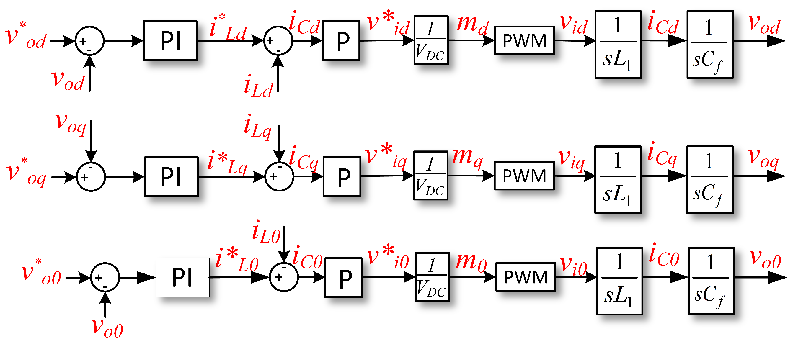
3. Proposed Control for Grid-Forming Converter

The proposed control of the GFC is done in the synchronous reference frame. Applying Kirchhoff’s Laws of voltage and current at GFC output in Figure 5, the following relations are obtained:
v i d = R L i L d w L 1 i L q + L d i L d d t + v o d
v i q = R L i L q + w L 1 i L d + L d i L q d t + v o q
v i 0 = R L i L 0 + L d i L 0 d t + v o 0
w C f v o q + C f d v o d d t = i L d i o d
w C f v o d + C f d v o q d t = i L q i o q
C f d v o 0 d t = i L 0 i o 0
From Equations (5)–(10), the LC filter block diagram is derived and presented in Figure 6. Analyzing the block diagram of the LC filter, it is possible to observe that the output voltage across the capacitor (vo) and the output current (io) through the inductor represent disturbances. There is also cross-coupling between the terms w L 1 i d , w L 1 i q , w C f v d , and w C f v q . Therefore, the GFC control must cancel out these terms to achieve a fast dynamic response.
The proposed control scheme for the GFC is shown in Figure 7. The voltage control loop is implemented with a parallel association of a PI controller and an RC controller. The RC assures zero steady-state error for a periodic reference, while the PI controller ensures a fast dynamic response. The current loop is in cascade with the voltage control loop, and a proportional controller (P) is used.
The PI and P controllers for the voltage and current loops are designed using a pole allocation technique with the RC deactivated [45]. A typical separation of 1/5 between current and voltage loop bandwidth allows achieving a good response for voltage source operation, as defined in [46]. Figure 8 depicts the GFC control block diagram, considering the cancellation of cross-coupling and internal feedbacks. Initially, considering a proper design of the current loop, it is possible to obtain the closed-loop transfer function neglecting the PWM effect ( v i * = v i ):
By adopting a cutoff frequency ( ω c i ) equal to one-fifth of the switching frequency, it is possible to determine the gain of the proportional controller of the current loop as:
K p i = L 1 w c i
For the voltage loop design, the internal current loop is considered to be the fastest, and it is represented by a unitary gain ( i L * = i L ) . Therefore, the closed loop transfer function is:
v o d * v o d = v o q * v o q = v o 0 * v o 0 = s K p v + K i v s 2 C f + s K p v + K i v
For the voltage loop, the fastest pole ( w c v 1 ) is adopted with frequency equal to (1/5) of cutoff frequency of current loop. In addition, the slowest pole ( w c v 2 ) is equal to (1/5) of the fastest voltage pole. The following expressions are obtained [47]:
K p v = w c v 1 + w c v 2 C f
K i v = w c v 1 × w c v 2 C f
For the RC it is necessary to obtain the gain K r and the LPF cut-off frequency. The LPF is used to limit the interaction between voltage and current loop, and to avoid instability of the system [18]. The LPF is implemented as a second-order Butterworth filter with a damping factor of ζ = 0.7 . Its transfer function is defined as:
H ( s ) = 1 s 2 w c 2 + 2 ζ s w c + 1
The cutoff frequency of LPF is chosen to be equal to (1/2) of the current loop bandwidth. Finally, the gain K r is determined by analyzing the equivalent closed-loop transfer function of the system, which includes all control loops, as illustrated in Figure 7. For this analysis, the dynamics of the inner current loop are neglected by assuming i L * = i L . To ensure system stability, the maximum permissible value of K r is identified based on the evaluation of gain and phase margins obtained from Bode plot analysis. A conservative value of K r is then selected to maintain a phase margin greater than 45° and a gain margin exceeding 6 dB, thereby ensuring robust performance under varying load conditions [48].

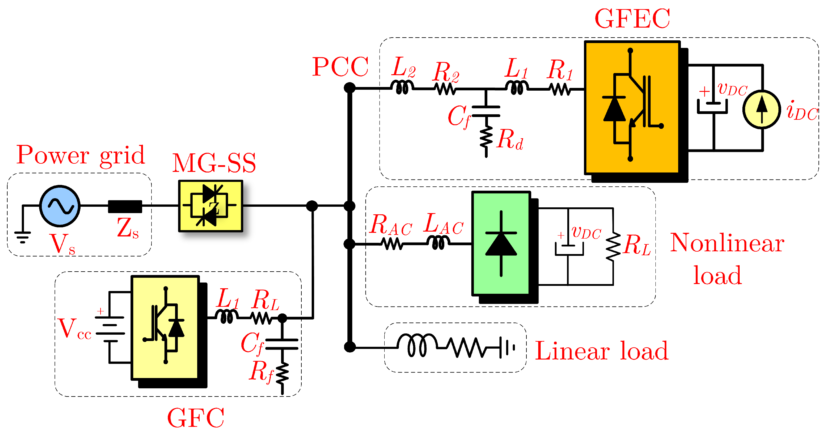
4. Microgrid Architecture Under Analysis

Figure 9 presents a simplified block diagram of the microgrid under study, while Table 1 lists its main electrical parameters. The paper considers only the islanded mode of operation, in which the MG-SS remains open, and the GFC is responsible for imposing voltage and frequency at the PCC, following a master–slave architecture.
The microgrid includes a GFEC, which can partially supply the loads, simulating the intermittency of a photovoltaic (PV) system. The electric loads of the microgrid include both linear and nonlinear components. The linear load is modeled as a constant impedance with RL characteristics. The nonlinear load consists of a three-phase diode rectifier with an inductive filter at the input, along with a capacitor and resistor on the DC side. This load model allows for the evaluation of unbalanced characteristics.
Figure 10 shows the equivalent circuit of the GFEC applied to the microgrid under study. It consists of a three-phase VSI with two-level space vector pulse width modulation (SVPWM) and an LCL filter [49,50]. The current source in parallel with the DC bus represents, for example, the intermittency of a photovoltaic system. The GFEC operates as a current source, injecting active power into the grid without contributing to reactive power regulation [51,52].
Figure 11 presents the block diagram of the GFEC control system, designed in the synchronous reference frame (dq). The control scheme incorporates several feedforward actions to cancel the cross-coupling effects of certain terms ( ω L i d and ω L i q ), voltage disturbances ( v d and v q ), and DC current variations ( i D C ). Notably, the control structure consists of a DC voltage loop, cascaded with a faster current loop, both regulated by PI controllers [51]. The voltage and current loop gains are designed using the pole placement technique. The cutoff frequency of the current loop ( ω c i ) is set to 1 / 10 of the switching frequency. Meanwhile, the voltage loop operates with two cutoff frequencies ( ω c v 1 , ω c v 2 ), set to 1 / 10 and 1 / 100 of the current loop cutoff frequency, respectively [45]. The PI controller gains are determined based on these relationships and are presented in Table 2.
K p i = ( L 1 + L 2 ) w c i
K i i = ( R 1 + R 2 ) w c i
K p V D C = 2 V D C ( w c v 1 + w c v 2 ) C D C 3 v d
K i V D C = 4 V D C ( w c v 1 × w c v 2 ) C D C 3 v d
The GFC shown in Figure 9 comprises a VSI that can operate in single-phase or three-phase configurations. An LC filter is employed to ensure a sinusoidal output voltage. On the DC side, an ESS is utilized, typically consisting of electrochemical battery banks, primarily for economic considerations [53]. For low-voltage ESS applications, an additional stage involving a buck-boost converter is included [27,54]. Table 3 presents the parameters for all controllers calculated for GFC under analysis.
The dynamic stiffness characteristic is used to evaluate the proposed control, a very useful concept in the theory of DC electrical machines, which can be applied to VSI [47]. This concept is based on the transfer function of (20), and shows how much of output current is necessary to perturb the output voltage in one volt. In Figure 12 is plotted the transfer function defined in (20) with all defined gain values for the GFC presented in Table 3.
i d q 0 ( s ) v d q 0 ( s ) v o * = 0 = s L 1 s 2 L 1 C f + C i ( s ) C f + C i ( s ) [ R ( s ) + C v ( s ) ]
C i ( s ) = K p i
C v ( s ) = K p v + K i v s
R ( s ) = K R 1 e s T 2
In Figure 12, it is possible to note that with the proposed RC control, the gain in the DC level and the even harmonics is increased compared to the condition where only the PI and P controllers are used. Thus, the voltage source characteristics are improved. The proposed control can be applied to a three-phase VSI with three legs to produce a three-wire system by simply eliminating the control of the zero-sequence in the voltage and current loop.

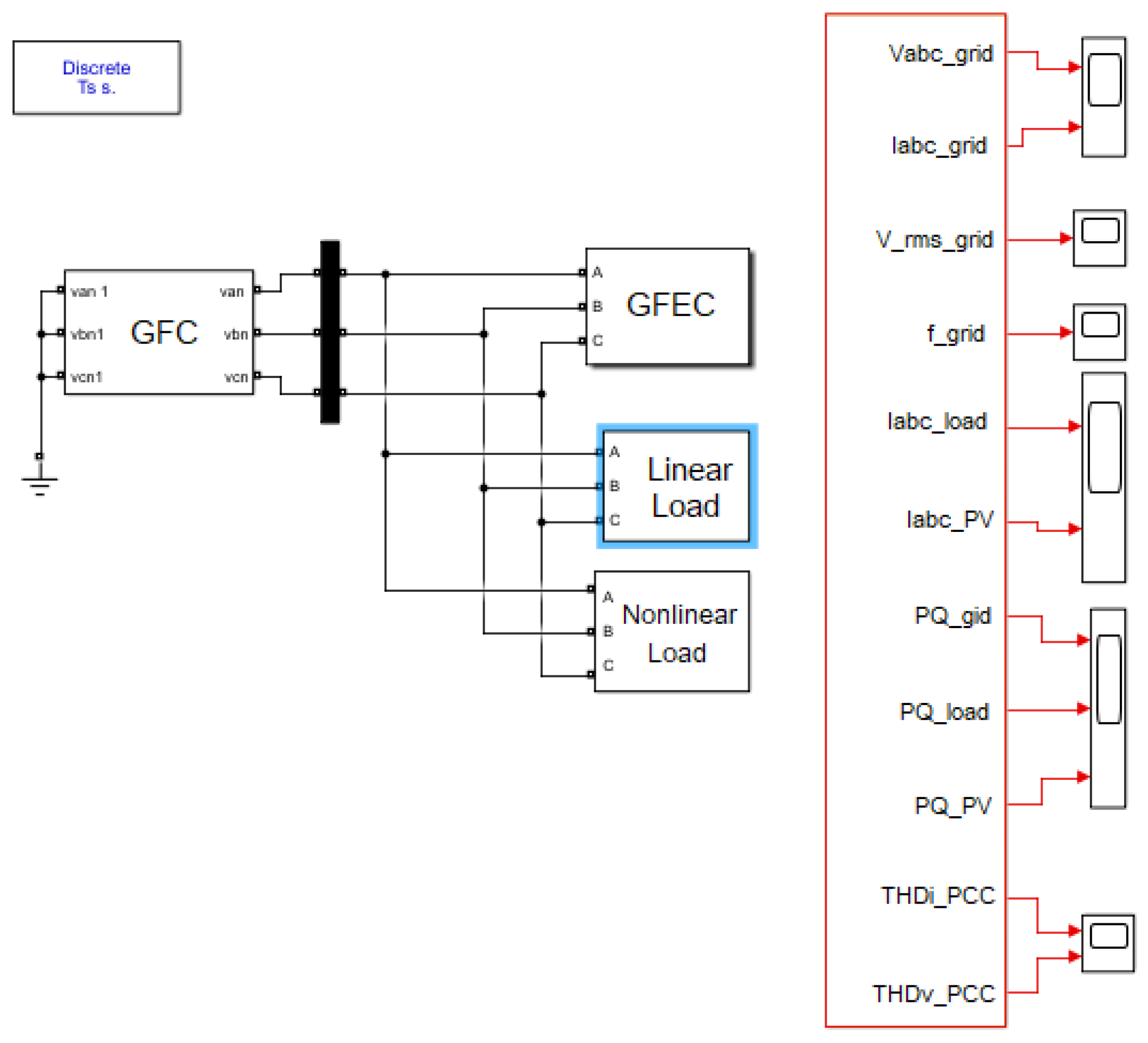
5. Simulation Results of the Microgrid
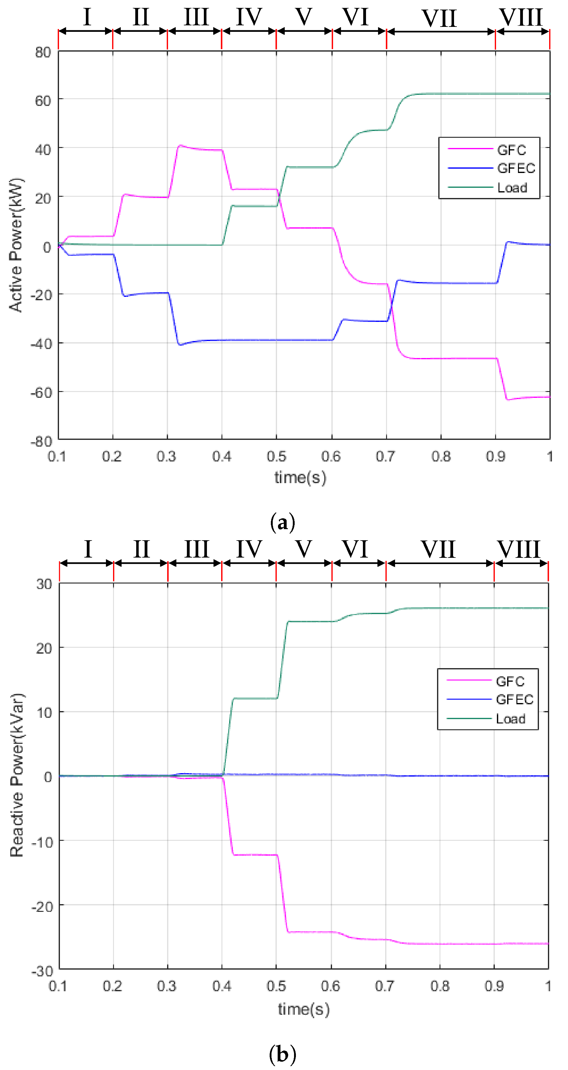
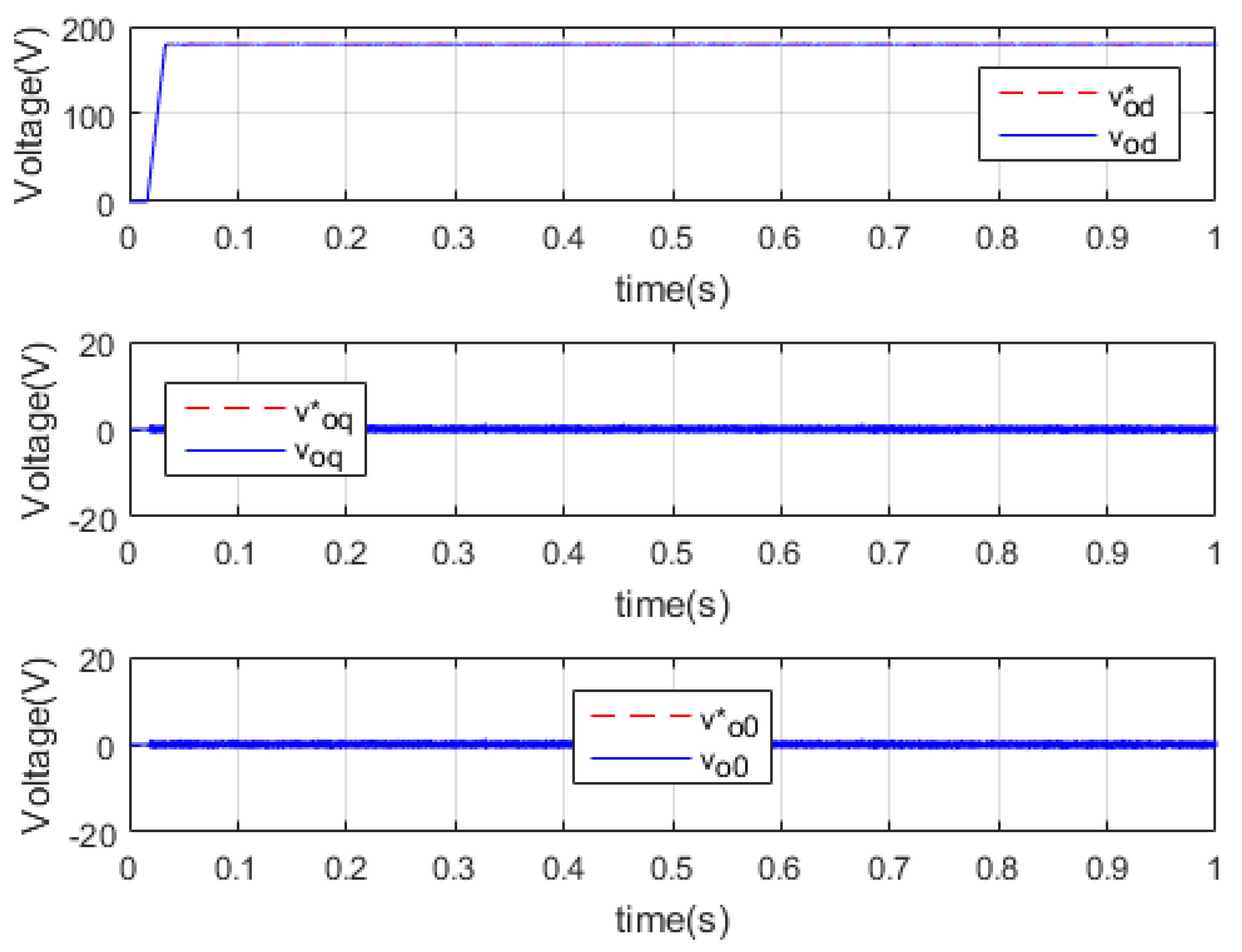
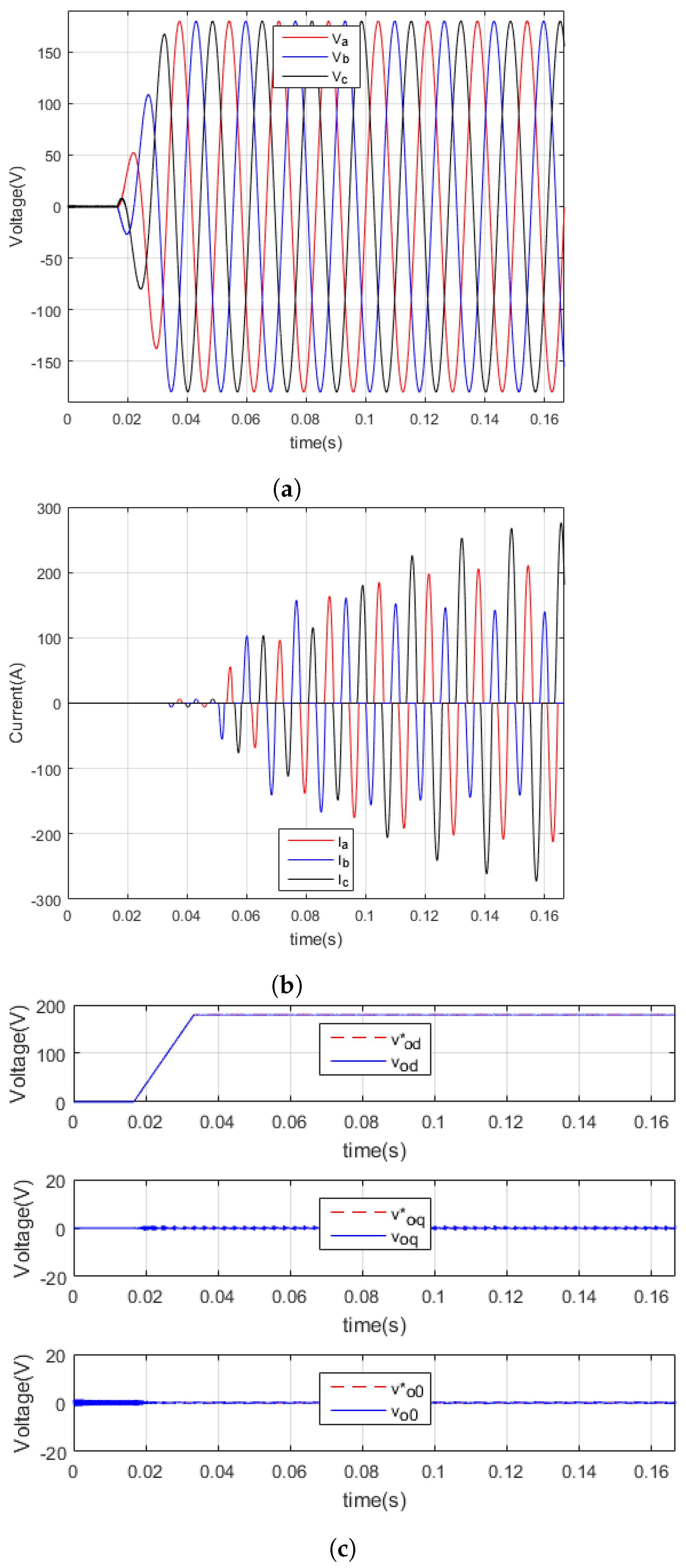
The microgrid model is developed in MATLAB/Simulink 2015b, and its operation is evaluated in two scenarios. In the first scenario, the microgrid operates with a balanced load in the presence of the GFEC. By contrast, the second scenario analyzes the GFC operation with an unbalanced nonlinear load. Figure 13 shows the MATLAB/Simulink interface with the developed microgrid model.

5.1. Scenario I

In the first scenario, a simulation period of 1 second is adopted. The following sequence describes the connection of loads, sources, and other microgrid elements that shape the power profile and generate active and reactive power flow at the PCC, as illustrated in Figure 14.
  • t = 0 s—PCC is energized by the GFC;
  • t = 0.1 s (I)—DC current in GFEC is adjusted to 8 A;
  • t = 0.2 s (II)—DC current in GFEC is adjusted to 40 A;
  • t = 0.3 s (III)—DC current in GFEC is adjusted to 80 A;
  • t = 0.4 s (IV)—RL load is connected with (16 + j12) kVA;
  • t = 0.5 s (V)—RL load is connected with (32 + j24) kVA;
  • t = 0.6 s (VI)—DC current in GFEC is adjusted to 64 A and R = 5.6 Ω is connected in DC side of nonlinear load;
  • t = 0.7 s (VII)—DC current in GFEC is adjusted to 32 A and R = 2.8 Ω is connected in DC side of nonlinear load;
  • t = 0.9 s (VIII)—GFEC is turned off;
  • t = 1 s—end of simulation.
From the results of Figure 14, it is possible to see that the GFEC injects a variable active power, with a peak of 40 kW. Without the connection of an electrical load, all active energy is absorbed by the GFC ESS. At the instant (t = 0.4 s), when the loads are connected, a power sharing between the GFC and GFEC can be observed, until (t = 0.9 s), when the GFEC stops operating. All reactive power flow is supplied by the GFC, without any contribution from the GFEC.
Figure 15 shows the voltage v a and current i a waveforms for the interval (t = 0.6–0.68 s), during which GFEC active power is reduced and a nonlinear load is connected, with the RL load already operating. This period is the most critical for the GFC, because the load current exhibits high THD and demands both active and reactive power. However, the GFC maintains a sinusoidal voltage.
Figure 16 presents the response of voltage closed loop for the dq0 axis. Initially in “d” axis, the voltage is increased in ramp and during all GFC operation it follows the reference. The same results are presented in “q” and “0” axis with good response. Finally, Figure 17 shows the root mean square voltage for each and the electrical frequency at PCC of the microgrid. During all the islanded mode of the microgrid, voltage and frequency are kept constant.

5.2. Scenario II

In the second scenario, the microgrid operates without the GFEC but in the presence of an unbalanced nonlinear load. Figure 18a shows that the GFC energizes the PCC with a suitable voltage slew-rate until it reaches its nominal value. From the results in Figure 18a and Figure 18b, it is possible to observe that the GFC can maintain a constant voltage with low distortion, even in the presence of unbalanced nonlinear loads. Additionally, in Figure 18c, it is possible to see that the voltage loop follows the reference.

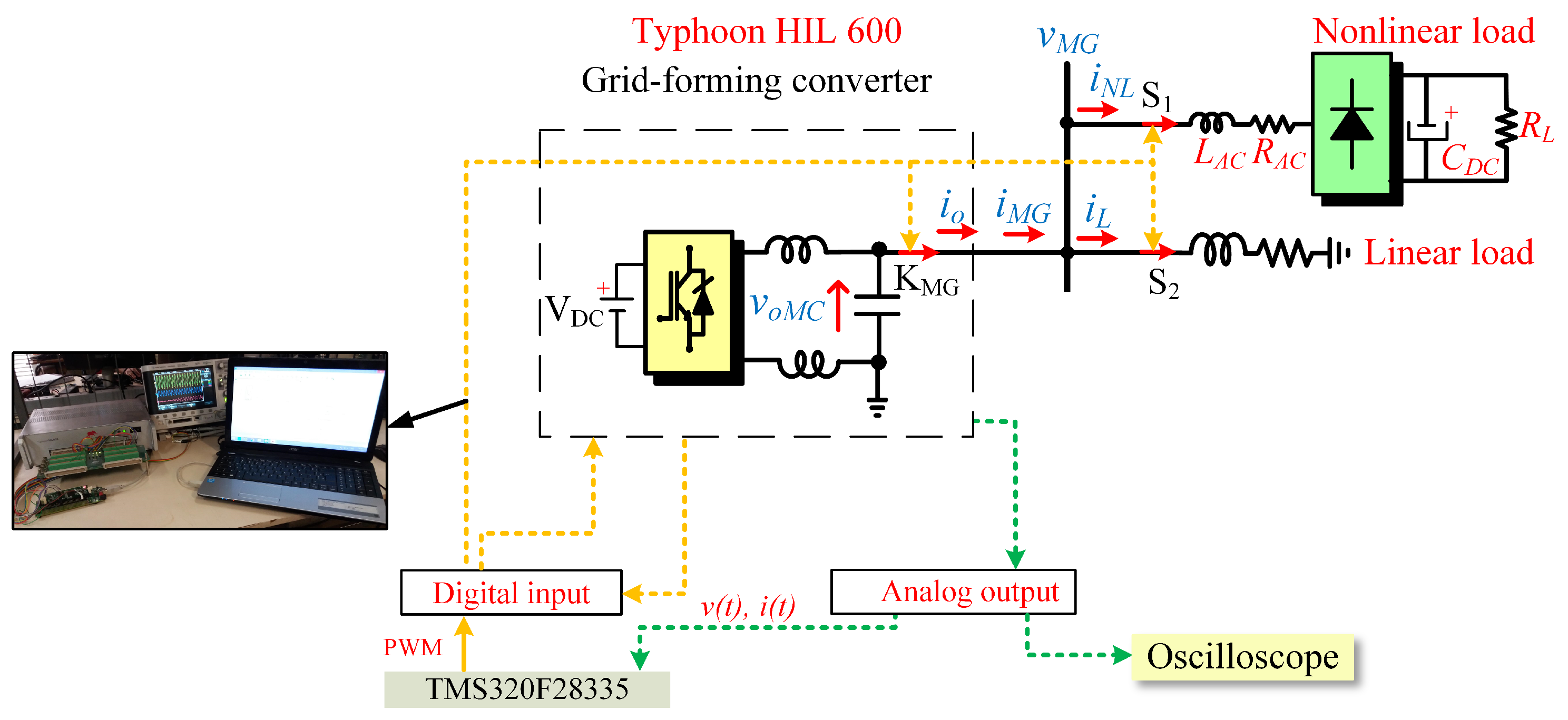
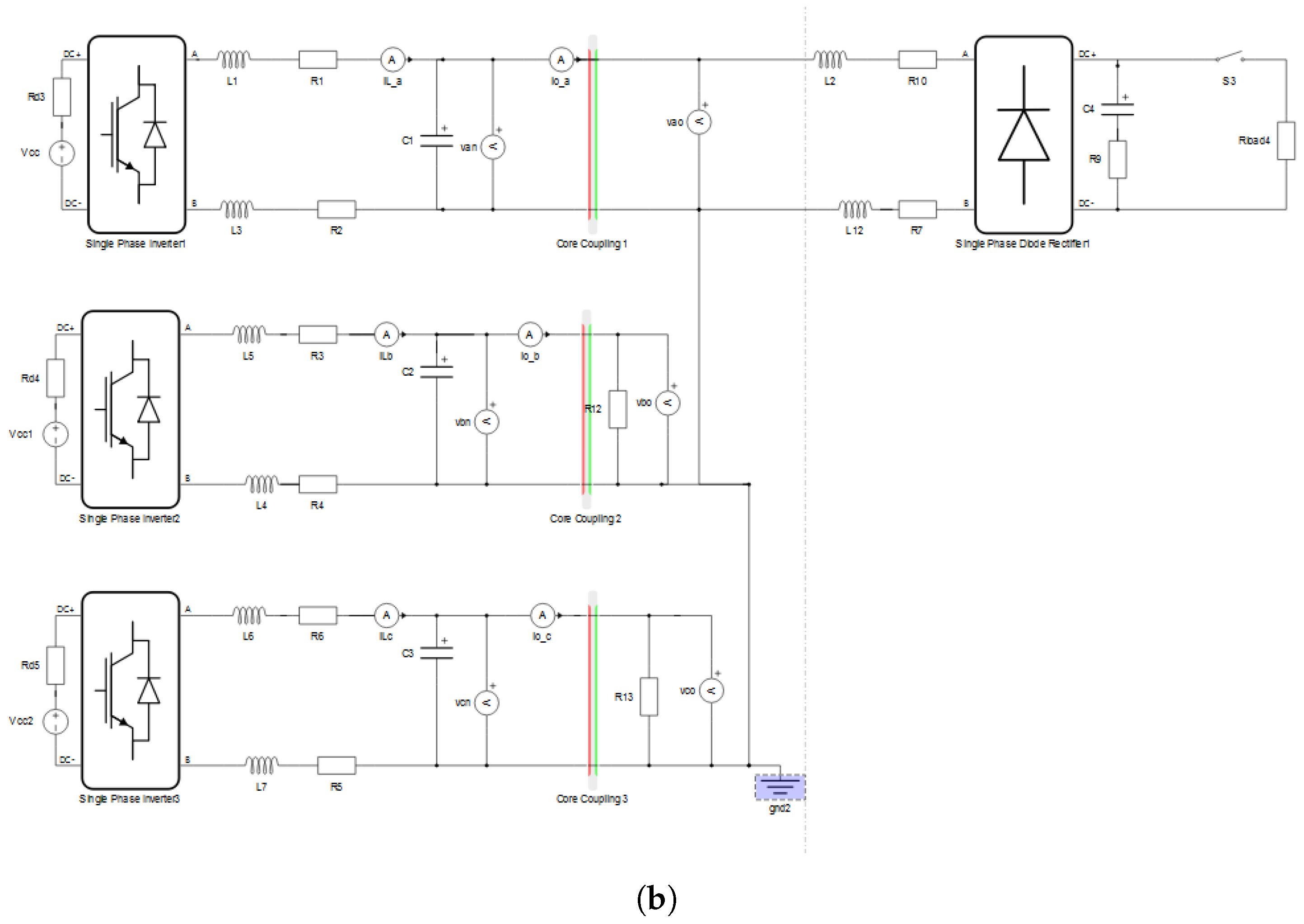
6. Hardware-in-the-Loop Results

HIL simulation offers a powerful means to validate microgrid control strategies under realistic, real-time operating conditions by coupling physical controller hardware with a simulated network environment. By accurately reproducing non-idealities such as converter dynamics, and sampling effects, HIL tests ensure that RCs and PI loops maintain stability and performance when subjected to unbalanced loads, and disturbances [55]. Moreover, HIL platforms like Typhoon HIL enable rapid iteration of control algorithms without the risk or cost associated with full-scale prototypes, significantly shortening development cycles and facilitating reproducibility across research labs and industry partners [56]. As a result, HIL simulation has become an indispensable step in the pathway from controller design to field deployment in modern microgrid systems [57].
HIL simulations using the Typhoon HIL 600 were conducted to evaluate the control of the GFC, as illustrated in Figure 19. The parameters used for the microgrid are identical to those listed in Table 1. Figure 20 illustrates the microgrid model implemented using the Typhoon HIL Control Center, developed through its Schematic Editor.
A Texas Instruments digital signal processor (TMS320F28335) was used to control the GFC, as shown in Figure 19. Additionally, two Agilent DDSO-X 2014A oscilloscopes, connected to the Typhoon HIL analog outputs, were used to capture the results. In the simulation, the GFEC was not considered due to the processing limitations of the HIL 600. All DSP programming was conducted using MATLAB/Simulink Embedded Coder through block diagrams, as detailed in [58] and illustrated in Figure 7.

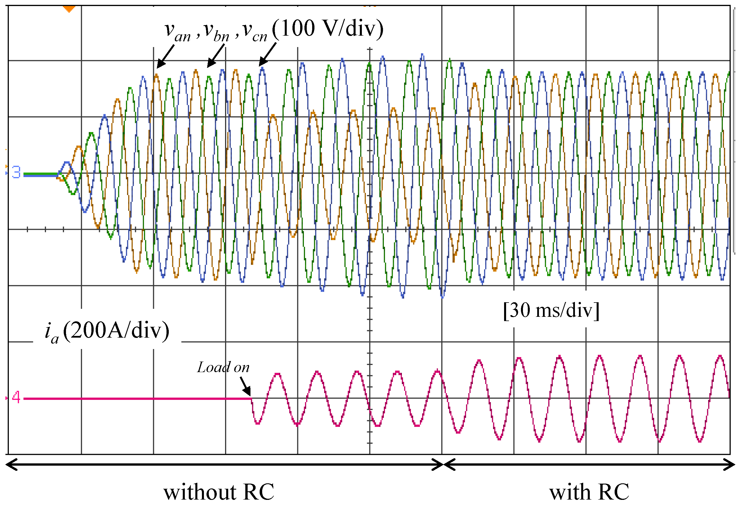
6.1. Scenario III—Single-Phase Linear Load

In Scenario III, a single-phase RL linear load with constant impedance is connected to phase “a” of the three-phase GFC. The main results are presented in Figure 21, showing the voltage and current at the GFC output.
Initially, the GFC output voltage is zero, with all switches open ( S M G , S 1 , and S 2 ). At t = 23 ms, the voltage gradually increases in a ramp with no load connected to the GFC. At t = 60 ms, S M G is connected, and the voltage reaches its nominal value, exhibiting unbalanced characteristics due to the RC being disabled. At t = 100 ms S 2 is closed, and a single-phase linear load is connected, causing a voltage sag in phase “a”. However, the RC is enabled at t = 180 ms, and the voltage returns to its nominal value with a balanced characteristic.
Table 4 presents the main values of RMS voltage and current, along with voltage THD, for each time interval. During the first interval (0–90 ms), a voltage imbalance is observed. In the second interval (60–180 ms), with the RC disabled, the RMS value of voltage v a n decreases due to the load connection, as the PI controller does not eliminate the steady-state error in the voltage control loop. Although the voltage THD slightly decreases following the load connection, the imbalance persists. When the RC is enabled in the third interval (180–300 ms), the voltage becomes balanced, the voltage THD is further reduced, and the load current increases.
Also, Table 4 highlights significant overvoltage events during the load connection without the RC. From 60–180 ms, the RMS voltage values increase substantially, especially in phases v b n and v c n , which reach 138.4 V and 147.7 V, respectively. These values represent deviations of approximately 9% and 16% above the nominal voltage level (127 V). In contrast, the initial interval (0–90 ms) shows relatively balanced voltages, with v a n at 129.0 V and v c n at 130.3 V, although already slightly above nominal. By the 180–300 ms interval, with the RC enabled, voltage levels return to near-nominal values, with v a n = 128.3 V and v c n = 130.2 V, and the current i a increases to 106.3 A. The corresponding total harmonic distortion (THD) values also decrease significantly, with all phases remaining below 0.7%. These results indicate that the overvoltage condition is effectively mitigated by the application of the RC.
Comparing the results from Table 4 between the intervals 60–180 ms (without RC) and 180–300 ms (with RC), a clear improvement in power quality can be observed when the RC is applied. During 60–180 ms, phase voltage imbalance is evident, with RMS values of v a n = 82.33 V, v b n = 138.4 V, and v c n = 147.7 V. When RC is enabled (180–300 ms), these values become more balanced: v a n = 128.3 V, v b n = 126.8 V, and v c n = 130.2 V. Furthermore, the voltage THD is significantly reduced across all phases. For instance, the THD in v a n decreases from 2.15% to 0.59%. The load current i a also increases from 67.9 A to 106.3 A, indicating that with better voltage regulation, more power is delivered to the load. Overall, these results demonstrate that RC enhances voltage symmetry, reduces harmonic distortion, and improves load current.

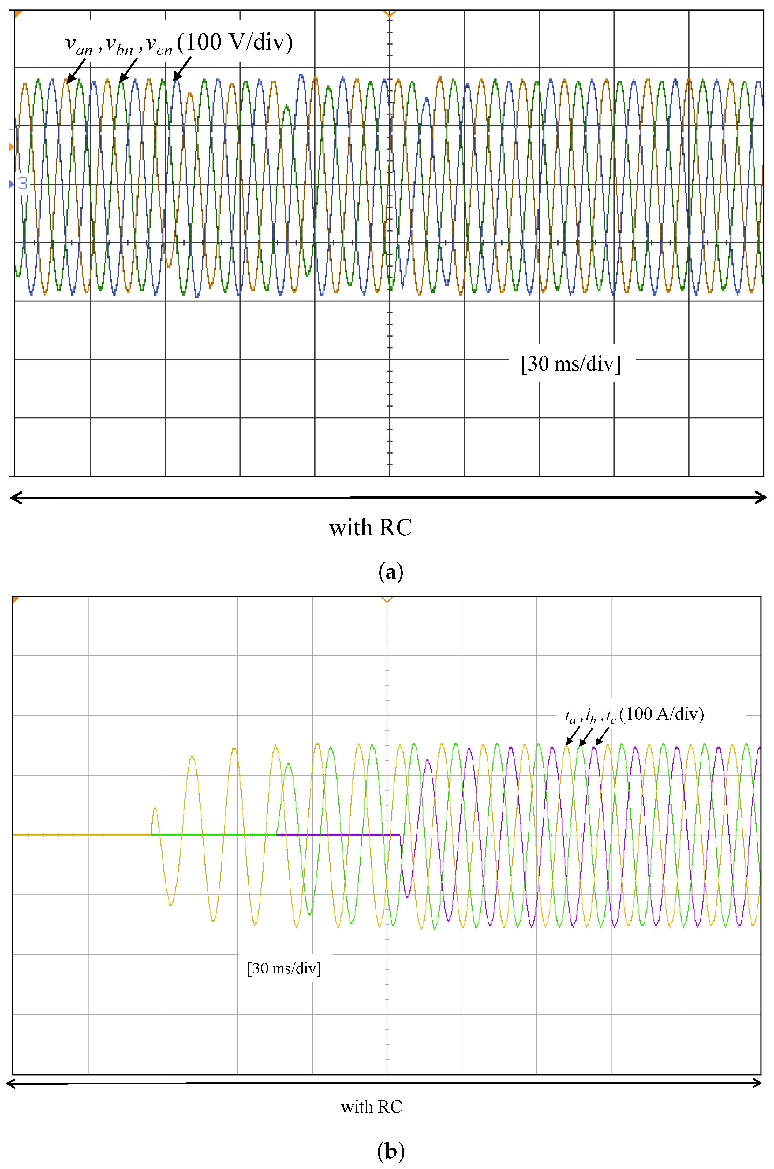
6.2. Scenario IV—Transition Between the Connection of Unbalanced to Balanced Linear Load

In Scenario IV, the transition from an unbalanced to a balanced load at the GFC output is evaluated. This scenario considers an RL linear load with constant impedance. Figure 22 presents the main results, initially considering the RC disabled in the voltage loop. Specifically, Figure 22a shows the phase voltage at the GFC output, while Figure 22b illustrates the corresponding line current. In contrast, Figure 23 depicts the results for the same scenario but now considering the RC enabled in the voltage loop.
Initially, the GFC imposes a nominal voltage at its output, and S M G is connected. At t = 50 , ms , an RL load is connected to phase a through S 2 . Subsequently, at t = 100 ms , a second RL load is connected to phase b, and finally, at t = 150 ms , a third RL load is connected to phase c.
Table 5 and Table 6 present the main RMS voltage and current values per time interval, along with the voltage THD, without and with RC, respectively.
A comparison between Table 5 (without RC) and Table 6 (with RC) is presented below, organized by time interval:
  • 0–50 ms: Both cases show balanced RMS voltages close to nominal values. However, voltage THD is slightly lower with RC: 0.69% in v a n (with RC) versus 2.44% (without RC).
  • 50–100 ms: This period exhibits major differences. Without RC, there is a strong voltage imbalance with v a n = 82.44 V and v c n = 148 V, while with RC, voltages remain balanced around 127 V. Voltage THD is significantly reduced from 2.11% to 0.76% in v a n , and current increases from 67.17 A to 106.1 A, reflecting improved power delivery.
  • 100–150 ms: Without RC, there is severe imbalance and overvoltage in v c n = 167.5 V, with v a n dropping to 94.77 V. With RC, voltages are nearly nominal and balanced. The THD in v a n improves from 1.99% to 0.68%, and i a increases from 77.46 A to 107 A, confirming better system behavior with RC.
  • 150–300 ms: This steady-state period also benefits from RC. Voltage THD is reduced from 1.31% to 0.50% in v a n , and all three-phase currents show a slight increase: i a from 103.2 A to 106.4 A, i b from 101 A to 107.4 A, and i c from 103.1 A to 106.4 A, indicating enhanced load supply capability.
These comparisons demonstrate that RC enhances voltage balance, reduces harmonic distortion, and improves current delivery across all operating intervals.

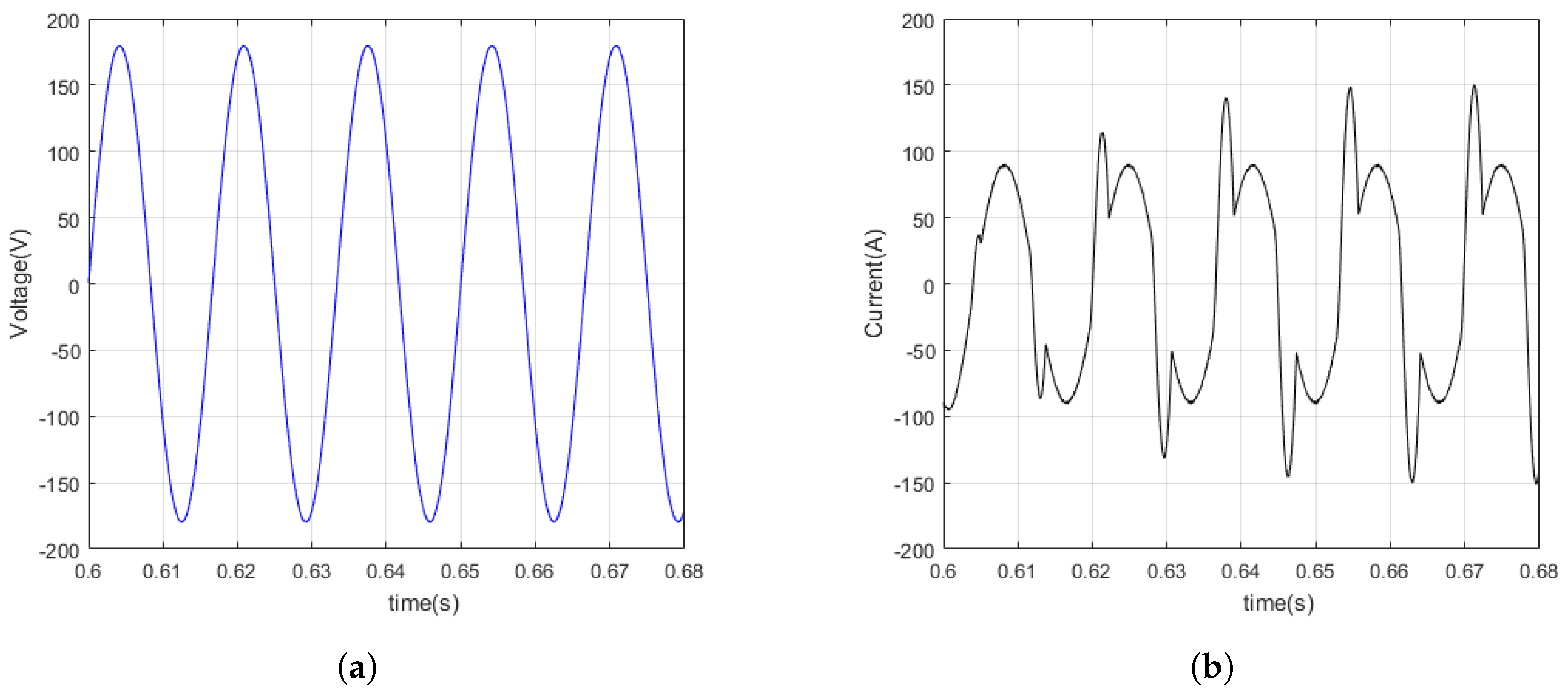
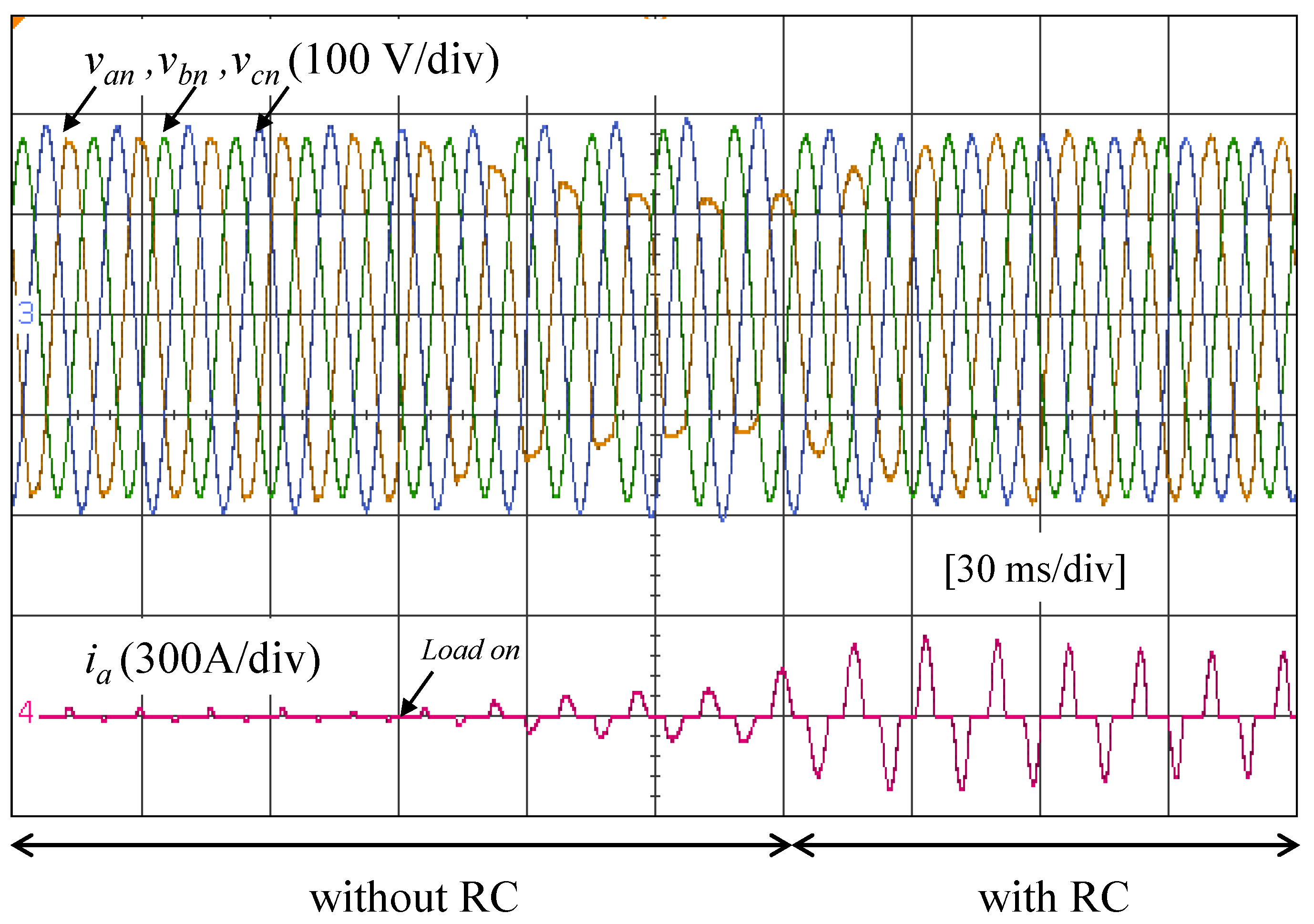
6.3. Scenario V—Single-Phase Nonlinear Load

In the last scenario, a single-phase nonlinear load is connected to phase “a” of the GFC. The nonlinear load consists of a full-bridge diode rectifier, an inductive filter on the input side, and a capacitor and resistor on the DC side. The main results are presented in Figure 24, showing the voltage and current at the GFC output.
Initially, from 0 to 90 ms, the GFC operates without the RC in the voltage loop, supplying only the capacitive load connected through the DC side of the rectifier on phase “a” ( S M G and S 1 closed). During this interval, a voltage imbalance occurs at the GFC output. At t = 90 ms , a resistive load is connected to the DC side of the rectifier, causing a drop in the phase voltage v a n . At t = 180 ms , the RC is enabled, resulting in an increase in both the phase voltage v a n and the current. With the activation of the RC, the voltage THD is reduced, and the RMS current increases.
Table 7 presents the main results for Scenario V, which considers a single-phase nonlinear load. During the 0–90 ms interval, the system maintains relatively unbalanced voltage levels, with RMS values of 129.8 V, 127 V, and 136 V for v a n , v b n , and v c n , respectively. However, even in this initial period, the voltage THD is already significant, especially in phase v a n , which reaches 3.21%. The current i a also exhibits high harmonic content, with a THD of 126.18%.
In the following interval (90–180 ms), without RC, the distortion increases significantly. Voltage v a n drops to 96.06 V, and its THD rises to 16.39%, indicating severe waveform degradation due to the nonlinear nature of the load. Meanwhile, the current RMS drops to 53.18 A, and its THD remains high at 49.97%, which may be related to the power drawn by the nonlinear load.
Significant overvoltage conditions are observed during the second interval (90–180 ms), when the RC is disabled. In this interval, the RMS voltages of v b n and v c n rise to 132.6 V and 141.8 V, respectively, representing deviations of approximately 4.4% and 11.7% above the nominal voltage level (127 V). In contrast, during the third interval (180–300 ms), with the RC enabled, the voltages return to near-nominal levels. The RMS values of v a n , v b n , and v c n become 128.09 V, 126.5 V, and 129.7 V, respectively, showing improved voltage balance and a substantial reduction in overvoltage severity. These results confirm that the RC effectively mitigates overvoltage effects caused by the nonlinear load, helping restore voltage stability in the system.
From 180–300 ms, with the application of the RC, the voltage and current waveforms improves considerably. Although the voltage v a n still shows a THD of 4.71%, this is a substantial reduction compared to the previous interval. The RMS value of v a n also recovers to 128.09 V. Most notably, the current i a increases to 98.39 A, and its THD decreases to 76.05%, confirming that the RC contributes to a significant improvement in power quality, mitigating the effects of the nonlinear load.
Comparing the results of Table 7 between the intervals 90–180 ms (without RC) and 180–300 ms (with RC), it is evident that the application of the RC improves the voltage quality under nonlinear load conditions. In the interval without RC, the voltage RMS values are highly unbalanced, with v a n = 96.06 V, v b n = 132.6 V, and v c n = 141.8 V. With RC applied, the voltages become more balanced: v a n = 128.09 V, v b n = 126.5 V, and v c n = 129.7 V. Additionally, the total harmonic distortion of voltage in phase “a” ( v a n ) is significantly reduced from 16.39% to 4.71%, demonstrating the RC’s ability to suppress harmonics. The RMS current i a increases from 53.18 A to 98.39 A, indicating enhanced power delivery, although the current distortion ( THD i a ) increases from 49.97% to 76.05% due to the presence of the nonlinear load. Overall, RC improves voltage regulation and harmonic suppression, but further compensation may be needed to reduce current distortion.

7. Conclusions

This paper presented the design, implementation, and evaluation of a plug-in RC specifically tuned for even harmonics, integrated into a GFC operating within a centralized AC microgrid in islanded mode. The proposed control strategy was applied in the synchronous reference frame and combined with a conventional PI controller to enhance voltage regulation and harmonic compensation.
A detailed microgrid model was developed in MATLAB/Simulink, enabling in-depth analysis of power flow and the dynamic behavior of voltages and currents at the PCC. Simulation results showed that the RC-based controller with even harmonics provided strong immunity to voltage imbalance and waveform distortion, even under unbalanced and nonlinear load conditions. The voltage at the PCC remained sinusoidal and stable, consistently exhibiting low THD.
To demonstrate practical feasibility, the control strategy was validated through real-time HIL testing using the Typhoon HIL 600 platform. The system was assessed under various operating conditions, including balanced and unbalanced, linear and nonlinear loads. In all scenarios, the proposed control method achieved notable improvements in voltage regulation, harmonic suppression, and current balancing, confirming its effectiveness and robustness.
Finally, future research will focus on conducting a comprehensive stability analysis of the proposed RC approach, particularly under load transitions and mode-switching scenarios. This includes the application of formal criteria such as Nyquist analysis, the evaluation of phase and gain margins, as well as robustness testing under parametric uncertainties and real-world disturbances. Additionally, developing a laboratory-scale microgrid prototype is planned to enable full experimental validation and field-oriented adjustments, paving the way for practical deployment and future scalability. Furthermore, the impacts of external factors—such as extreme weather conditions and electricity market dynamics—on the performance and resilience of centralized AC microgrids also warrant investigation [59,60].

Author Contributions

Conceptualization, H.M.A.A.; methodology, H.M.A.A.; software, H.M.A.A.; validation, H.M.A.A.; formal analysis, H.M.A.A., R.R.D.P. and S.M.S.; investigation, H.M.A.A., R.R.D.P. and S.M.S.; resources, H.M.A.A., R.R.D.P. and S.M.S.; data curation, H.M.A.A.; writing—original draft preparation, H.M.A.A.; writing—review and editing, H.M.A.A., R.R.D.P. and S.M.S.; visualization, H.M.A.A., R.R.D.P. and S.M.S.; supervision, H.M.A.A.; project administration, H.M.A.A.; funding acquisition, H.M.A.A. All authors have read and agreed to the published version of the manuscript.

Funding

This study was partially funded by the Coordination for the Improvement of Higher Education Personnel (CAPES)—Finance Code 001, and by the Federal University of Espirito Santo (UFES), Brazil.

Data Availability Statement

Data are contained within the article.

Acknowledgments

The authors thank the Graduate Program in Electrical Engineering of the Federal University of Espirito Santo for supporting this research, the government agencies CAPES and CNPQ for their financial support.

Conflicts of Interest

The authors declare no conflicts of interest.

References

  1. Hatziargyriou, N.; Asano, H.; Iravani, R.; Marnay, C. Microgrids. IEEE Power Energy Mag. 2007, 5, 78–94. [Google Scholar] [CrossRef]
  2. Medina, P.; Bizuayehu, A.W.; Catalão, J.P.; Rodrigues, E.M.; Contreras, J. Electrical energy storage systems: Technologies’ state-of-the-art, techno-economic benefits and applications analysis. In Proceedings of the 2014 47th Hawaii International Conference on System Sciences, Waikoloa, HI, USA, 6–9 January 2014; IEEE: Piscataway, NJ, USA, 2014; pp. 2295–2304. [Google Scholar]
  3. Cheng, Q.; Zhang, Z.; Wang, Y.; Zhang, L. A Review of Distributed Energy Systems: Technologies, Classification, and Applications. Sustainability 2025, 17, 1346. [Google Scholar] [CrossRef]
  4. Rocabert, J.; Luna, A.; Blaabjerg, F.; Rodriguez, P. Control of power converters in AC microgrids. IEEE Trans. Power Electron. 2012, 27, 4734–4749. [Google Scholar] [CrossRef]
  5. Ansari, S.; Chandel, A.; Tariq, M. A Comprehensive Review on Power Converters Control and Control Strategies of AC/DC Microgrid. IEEE Access 2021, 9, 17998–18015. [Google Scholar] [CrossRef]
  6. Xu, L.; Miao, Z.; Fan, L. Coordinated control of a solar and battery system in a microgrid. In Proceedings of the PES T&D 2012, Orlando, FL, USA, 7–10 May 2012; IEEE: Piscataway, NJ, USA, 2012; pp. 1–7. [Google Scholar]
  7. Lopes, J.P.; Moreira, C.L.; Madureira, A. Defining control strategies for microgrids islanded operation. IEEE Trans. Power Syst. 2006, 21, 916–924. [Google Scholar] [CrossRef]
  8. Azevedo, G.M.; Cavalcanti, M.C.; Neves, F.A.; Limongi, L.R.; Bradaschia, F. A control of microgrid power converter with smooth transient response during the change of connection mode. In Proceedings of the 2013 Brazilian Power Electronics Conference, Gramado, Brazil, 27–31 October 2013; IEEE: Piscataway, NJ, USA, 2013; pp. 1008–1015. [Google Scholar]
  9. Salem, Q.; Aljarrah, R.; Karimi, M.; Al-Quraan, A. Grid-Forming Inverter Control for Power Sharing in Microgrids Based on P/f and Q/V Droop Characteristics. Sustainability 2023, 15, 11712. [Google Scholar] [CrossRef]
  10. Arghir, C.; Jouini, T.; Dörfler, F. Grid-forming control for power converters based on matching of synchronous machines. Automatica 2018, 95, 273–282. [Google Scholar] [CrossRef]
  11. Zhou, J.; Sun, Y.; Chen, S.; Lan, T. A Fast Repetitive Control Strategy for a Power Conversion System. Electronics 2024, 13, 1186. [Google Scholar] [CrossRef]
  12. Arjomandi-Nezhad, A.; Guo, Y.; Pal, B.C.; Varagnolo, D. A Model Predictive Approach for Enhancing Transient Stability of Grid-Forming Converters. arXiv 2023, arXiv:2308.01020. [Google Scholar] [CrossRef]
  13. Häberle, V.; He, X.; Huang, L.; Dörfler, F.; Low, S. Quantitative Decentralized Stability Certificates for Grid-Forming Converter Control. arXiv 2025, arXiv:2503.05403. [Google Scholar] [CrossRef]
  14. Ngamroo, I.; Surinkaew, T.; Mitani, Y. Intelligence-Driven Grid-Forming Converter Control for Islanding Microgrids. J. Mod. Power Syst. Clean Energy 2025. [Google Scholar] [CrossRef]
  15. Ribeiro, R.L.d.A.; Oshnoei, A.; Anvari-Moghaddam, A.; Blaabjerg, F. Adaptive Grid Impedance Shaping Approach Applied for Grid-Forming Power Converters. IEEE Access 2022, 10, 83096–83110. [Google Scholar] [CrossRef]
  16. Wang, C.; Li, X.; Guo, L.; Li, Y. A seamless operation mode transition control strategy for a microgrid based on master-slave control. Sci. China Technol. Sci. 2012, 55, 1644–1654. [Google Scholar] [CrossRef]
  17. de Araújo, L.S.; Narvaez, D.I.; Villalva, M.G.; de Siqueira, T. Controle Droop para Conversor de Suporte Conectado a Bateria em Microrrede Monofásica de Baixa Tensão. In Proceedings of the VI Simpósio Brasileiro de Sistemas Elétricos, Natal, RN, Brazil, 22–25 May 2016. [Google Scholar]
  18. Oliveira, A.F.B.O.; Silva, S.M.; Santos, C.H.; Cardoso Filho, B.d.J. Aplicação do controle repetitivo a inversor PWM monofásico com filtro LC de saída utilizado em fonte programável CA. Eletrônica Potência 2013, 18, 1161–1169. [Google Scholar] [CrossRef]
  19. Michels, L.; Gründling, H.A. Procedimentos de Projeto de Controladores Repetitivos para o Estágio de Saída de Fontes Ininterruptas de Energia. Eletrônica Potência 2005, 10, 39–50. [Google Scholar] [CrossRef]
  20. Wang, J.; Chang, N.C.P.; Feng, X.; Monti, A. Design of a generalized control algorithm for parallel inverters for smooth microgrid transition operation. IEEE Trans. Ind. Electron. 2015, 62, 4900–4914. [Google Scholar] [CrossRef]
  21. Kim, T.; Barry, N.G.; Kim, W.; Santoso, S.; Wang, W.; Dugan, R.C.; Ramasubramanian, D. Voltage Balancing Capability of Grid-Forming Inverters. IEEE Open Access J. Power Energy 2022, 9, 479–488. [Google Scholar] [CrossRef]
  22. de Matos, J.G.; de Souza Ribeiro, L.A.; de Carvalho Gomes, E. Power control in isolated Microgrids with renewable distributed energy sources and battey banks. In Proceedings of the 2013 International Conference on Renewable Energy Research and Applications (ICRERA), Madrid, Spain, 20–23 October 2013; IEEE: Piscataway, NJ, USA, 2013; pp. 258–263. [Google Scholar]
  23. Ravanji, M.H.; Rathnayake, D.B.; Mansour, M.Z.; Bahrani, B. Impact of Voltage-Loop Feedforward Terms on the Stability of Grid-Forming Inverters and Remedial Actions. IEEE Trans. Energy Convers. 2023, 38, 1554–1565. [Google Scholar] [CrossRef]
  24. Cho, Y.; Byen, B.J.; Lee, H.S.; Cho, K.Y. A Single-Loop Repetitive Voltage Controller with an Active Damping Control Technique. Energies 2017, 10, 673. [Google Scholar] [CrossRef]
  25. Du, Y.; Wang, X.; Zhang, H.; Wen, J. Challenges and potential solutions of grid-forming converters in renewable energy dominated power systems. Front. Energy Res. 2020, 8, 1040781. [Google Scholar] [CrossRef]
  26. Miveh, M.R.; Rahmat, M.F.; Ghadimi, A.A.; Mustafa, M.W. Power quality improvement in autonomous microgrids using multi-functional voltage source inverters: A comprehensive review. J. Power Electron. 2015, 15, 1054–1065. [Google Scholar] [CrossRef]
  27. e Silva, F.S.; Ribeiro, L.A.d.S.; de Matos, J.G. Bidirectional DC-AC converter for isolated microgrids with voltage unbalance reduction capabilities. In Proceedings of the 2014 IEEE Energy Conversion Congress and Exposition (ECCE), Pittsburgh, PA, USA, 14–18 September 2014; IEEE: Piscataway, NJ, USA, 2014; pp. 4985–4991. [Google Scholar]
  28. Gkountaras, A.; Dieckerhoff, S.; Sezi, T. Evaluation of current limiting methods for grid forming inverters in medium voltage microgrids. In Proceedings of the 2015 IEEE Energy Conversion Congress and Exposition (ECCE), Montreal, QC, Canada, 20–24 September 2015; IEEE: Piscataway, NJ, USA, 2015; pp. 1223–1230. [Google Scholar]
  29. Li, X.; Chen, Z.; Kumar, A. Adaptive Grid-Forming Control for Microgrids Under Uncertain Conditions. IEEE Access 2023, 11, 12345–12356. [Google Scholar]
  30. Liu, Q.; Tao, Y.; Liu, X.; Deng, Y.; He, X. Voltage unbalance and harmonics compensation for islanded microgrid inverters. IET Power Electron. 2014, 7, 1055–1063. [Google Scholar] [CrossRef]
  31. Ryan, M.J.; Lorenz, R.D. A high performance sine wave inverter controller with capacitor current feedback and “back-emf” decoupling. In Proceedings of the PESC’95-Power Electronics Specialist Conference, Atlanta, GA, USA, 18–22 June 1995; IEEE: Piscataway, NJ, USA, 1995; Volume 1, pp. 507–513. [Google Scholar]
  32. Natesan, C.; Ajithan, S.K.; Palani, P.; Kandhasamy, P. Survey on microgrid: Power quality improvement techniques. Int. Sch. Res. Not. 2014, 2014, 342019. [Google Scholar] [CrossRef]
  33. Tang, M.; Caspar, M.; Sonn, G. Application of New Structure Frequency Adaptive Selective Harmonics Repetition Control for Grid-Connected Converter. Energy Convers. Manag. 2021, 251, 114996. [Google Scholar]
  34. Ufnalski, B.; Straś, A.; Grzesiak, L. High Quality Repetitive Control System for a Grid-Tied Converter under Distorted Grid Voltage Conditions—Design and Implementation. Bull. Pol. Acad. Sci. Tech. Sci. 2021, 69, e136739. [Google Scholar] [CrossRef]
  35. Straś, A.; Ufnalski, B.; Kaszewski, A. Design of a Repetitive Control for a Three-Phase Grid-Tied Converter under Distorted Grid Voltage Conditions. Energies 2023, 16, 754. [Google Scholar] [CrossRef]
  36. Zhou, K.; Wang, D. Digital repetitive learning controller for three-phase CVCF PWM inverter. IEEE Trans. Ind. Electron. 2001, 48, 820–830. [Google Scholar] [CrossRef]
  37. Antunes, H.M.; Silva, S.M.; Brandao, D.I.; Ferreira, R.V.; Braz de Jesus Filho, C. Analysis of a grid-forming converter based on repetitive control in centralized AC microgrid. In Proceedings of the 2017 IEEE 8th International Symposium on Power Electronics for Distributed Generation Systems (PEDG), Florianopolis, Brazil, 17–20 April 2017; IEEE: Piscataway, NJ, USA, 2017; pp. 1–8. [Google Scholar]
  38. Francis, B.A.; Wonham, W.M. The internal model principle for linear multivariable regulators. Appl. Math. Optim. 1975, 2, 170–194. [Google Scholar] [CrossRef]
  39. Cuiyan, L.; Dongchun, Z.; Xianyi, Z. Theory and applications of the repetitive control. In Proceedings of the SICE 2004 Annual Conference, Sapporo, Japan, 4–6 August 2004; IEEE: Piscataway, NJ, USA, 2004; Volume 1, pp. 27–34. [Google Scholar]
  40. Liang, F.; Lee, H.J.; Zhao, Q. A Novel Fractional Delay Proportional–Integral Multi-Resonant-Type Repetitive Control Based on a Farrow-Structure Filter for Grid-Tied Inverters. Electronics 2023, 12, 4010. [Google Scholar] [CrossRef]
  41. Shahgholian, G.; Moradian, M.; Fathollahi, A. Droop control strategy in inverter-based microgrids: A brief review on analysis and application in islanded mode of operation. IET Renew. Power Gener. 2025, 19, e13186. [Google Scholar] [CrossRef]
  42. Zou, Z.; Zhou, K.; Wang, Z.; Cheng, M. Fractional-order repetitive control of programmable AC power sources. IET Power Electron. 2014, 7, 431–438. [Google Scholar] [CrossRef]
  43. Chen, D.; Zhang, J.; Qian, Z. An improved repetitive control scheme for grid-connected inverter with frequency-adaptive capability. IEEE Trans. Ind. Electron. 2012, 60, 814–823. [Google Scholar] [CrossRef]
  44. Lu, W.; Zhou, X.; Hu, L.; Fang, W. Generic selective harmonic repetitive control strategy for grid-connected converters. Energy Rep. 2025, 13, 5064–5076. [Google Scholar] [CrossRef]
  45. Yazdani, A.; Iravani, R. Voltage-Sourced Converters in Power Systems: Modeling, Control, and Applications; John Wiley & Sons: Hoboken, NJ, USA, 2010. [Google Scholar]
  46. Silva, S.; Filho, B. Component-minimized voltage sag compensators. In Proceedings of the Conference Record of the 2002 IEEE Industry Applications Conference. 37th IAS Annual Meeting (Cat. No.02CH37344), Pittsburgh, PA, USA, 13–18 October 2002; Volume 2, pp. 883–889. [Google Scholar] [CrossRef]
  47. Ryan, M.J.; Brumsickle, W.E.; Lorenz, R.D. Control topology options for single-phase UPS inverters. IEEE Trans. Ind. Appl. 1997, 33, 493–501. [Google Scholar] [CrossRef]
  48. Buso, S.; Mattavelli, P. Digital Control in Power Electronics; Springer: Berlin/Heidelberg, Germany, 2022. [Google Scholar]
  49. Rahman, S.A.; Varma, R.K. PSCAD/EMTDC model of a 3-phase grid connected photovoltaic solar system. In Proceedings of the 2011 North American Power Symposium, Boston, MA, USA, 4–6 August 2011; IEEE: Piscataway, NJ, USA, 2011; pp. 1–7. [Google Scholar]
  50. Reznik, A.; Simões, M.G.; Al-Durra, A.; Muyeen, S. LCL filter design and performance analysis for small wind turbine systems. In Proceedings of the 2012 IEEE Power Electronics and Machines in Wind Applications, Denver, CO, USA, 16–18 July 2012; IEEE: Piscataway, NJ, USA, 2012; pp. 1–7. [Google Scholar]
  51. Vechiu, I.; Curea, O.; Llaria, A.; Camblong, H. Control of power converters for microgrids. COMPEL-Int. J. Comput. Math. Electr. Electron. Eng. 2011, 30, 300–309. [Google Scholar] [CrossRef]
  52. Cupertino, A.; De Resende, J.; Pereira, H.; Júnior, S.S. A grid-connected photovoltaic system with a maximum power point tracker using passivity-based control applied in a boost converter. In Proceedings of the 2012 10th IEEE/IAS International Conference on Industry Applications, Fortaleza, Brazil, 5–7 November 2012; IEEE: Piscataway, NJ, USA, 2012; pp. 1–8. [Google Scholar]
  53. de Matos, J.G.; de Souza Ribeiro, L.A.; Freitas, F.S. Controle da potência gerada em microrredes autônomas e isoladas com fontes de energia renováveis e sistema de armazenamento com bancos de baterias. Eletrônica de Potência 2014, 19, 152–162. [Google Scholar] [CrossRef]
  54. Trintis, I.; Munk-Nielsen, S.; Teodorescu, R. Single stage grid converters for battery energy storage. In Proceedings of the 5th IET International Conference on Power Electronics, Machines and Drives (PEMD 2010), Brighton, UK, 19–21 April 2010; IET: Stevenage, UK, 2010; p. MO234. [Google Scholar]
  55. Kelm, P.; Wasiak, I.; Mieński, R.; Wędzik, A.; Szypowski, M.; Pawełek, R.; Szaniawski, K. Hardware-in-the-loop validation of an energy management system for LV distribution networks with renewable energy sources. Energies 2022, 15, 2561. [Google Scholar] [CrossRef]
  56. Araujo, L.S.; Brandao, D.I. Self-adaptive control for grid-forming converter with smooth transition between microgrid operating modes. Int. J. Electr. Power Energy Syst. 2022, 135, 107479. [Google Scholar] [CrossRef]
  57. Wang, J.; Pratt, A.; Prabakar, K.; Miller, B.; Symko-Davies, M. Development of an integrated platform for hardware-in-the-loop evaluation of microgrids prior to site commissioning. Appl. Energy 2021, 290, 116755. [Google Scholar] [CrossRef]
  58. Elrajoubi, A.; Ang, S.S.; Abushaiba, A. TMS320F28335 DSP programming using MATLAB Simulink embedded coder: Techniques and advancements. In Proceedings of the 2017 IEEE 18th Workshop on Control and Modeling for Power Electronics (COMPEL), Stanford, CA, USA, 9–12 July 2017; pp. 1–7. [Google Scholar] [CrossRef]
  59. Jiang, J.; Li, Y.; Yang, K.; Wang, S.; Wang, S. Stochastic Planning for Resilient Infrastructure of Distribution System Under Extreme Weather Events. IEEE Trans. Ind. Appl. 2024, 60, 2191–2200. [Google Scholar] [CrossRef]
  60. Xiao, D.; Chen, H. Stochastic Up to Congestion Bidding Strategy in the Nodal Electricity Markets Considering Risk Management. IEEE Access 2020, 8, 202428–202438. [Google Scholar] [CrossRef]
Figure 1. Simplified control diagram for a GFC.
Energies 18 03427 g001
Figure 2. Control strategies for GFC: (a) current control; (b) voltage control.
Energies 18 03427 g002
Figure 3. Equivalent control diagram for RC with K r = 1 for: (a) odd harmonics; (b) even harmonics.
Energies 18 03427 g003
Figure 4. Comparison between bode transfer functions for even and odd RC.
Energies 18 03427 g004
Figure 5. Four-wire GFC under analysis.
Energies 18 03427 g005
Figure 6. Block diagram of LC filter in synchronous reference frame.
Energies 18 03427 g006
Figure 7. Proposed control diagram for the GFC.
Energies 18 03427 g007
Figure 8. Simplified block diagram in synchronous reference frame with simplications.
Energies 18 03427 g008
Figure 9. Structure of the centralized three-phase four-wires AC microgrid.
Energies 18 03427 g009
Figure 10. Equivalent circuit for GFEC.
Energies 18 03427 g010
Figure 11. Control diagram for GFEC in dq frame.
Energies 18 03427 g011
Figure 12. Dynamic stifiness for GFC with proposed control.
Energies 18 03427 g012
Figure 13. The microgrid model developed in MATLAB/Simulink.
Energies 18 03427 g013
Figure 14. Power flow at PCC of microgrid: (a) active power; (b) reactive power.
Energies 18 03427 g014
Figure 15. Voltage and current at PCC of microgrid: (a) phase-voltage v a ; (b) line current i a .
Energies 18 03427 g015
Figure 16. Response of voltage loop from GFC.
Energies 18 03427 g016
Figure 17. RMS Voltage and frequency at PCC of microgrid.
Energies 18 03427 g017
Figure 18. Microgrid with unbalanced nonlinear load: (a) voltage at PCC of microgrid; (b) current at PCC of microgrid; (c) response of voltage loop for GFC.
Energies 18 03427 g018
Figure 19. Hardware-in-the-Loop validation.
Energies 18 03427 g019
Figure 20. The microgrid model developed in Typhoon HIL Control Center and its Schematic Editor with: (a) linear load; (b) nonlinear load.
Energies 18 03427 g020aEnergies 18 03427 g020b
Figure 21. Scenario III: main results for a single-phase linear load.
Energies 18 03427 g021
Figure 22. Scenario IV—Transition between the connection of unbalanced to balanced linear load without RC: (a) phase voltage; (b) line current.
Energies 18 03427 g022
Figure 23. Scenario IV—Transition between the connection of unbalanced to balanced linear load with RC: (a) phase voltage; (b) line current.
Energies 18 03427 g023
Figure 24. Main results of Scenario V with single-phase non linear load.
Energies 18 03427 g024
Table 1. Electrical characteristics of the microgrid under analysis.
SystemCharacteristics
GFC220 V, 60 Hz, 75 kVA, LC filter: R L = 10 m Ω , L 1 = 26 μ H ,
C f = 411 μ F , R F = 0.1 Ω , f s w = 15.36 kHz, V D C = 350 V
GFEC40 kVA, 220 V, f s w = 7.68 kHz, LCL filter: R i = 10 m Ω ,
L 1 = 730 μ H , R f = 0.2 Ω , C f = 55 μ F , R 2 = 10 m Ω ,
L 2 = 24 μ H , C D C = 9.4 mF , V D C = 500 V , V d = 180 V
Linear load220 V, 40 kVA, f p = 0.8 (lagged)
Nonlinear load220 V, 30 kW, R A C = 64 m Ω , L A C = 30 μ H ,
C D C = 28.8 mF , R l = 2.8 Ω
Table 2. Gains values for the controllers of GFEC.
LoopGains
DC voltage K p = 9.2 Ω 1 , K i = 810.7 Ω 1
Current K p = 3.6 Ω , K i = 96.5 Ω
Table 3. Loop gains for the proposed controller of GFC.
LoopGains
Voltage K p = 1.9 Ω 1 , K i = 1225 Ω 1 , K r = 30 Ω 1
Current K p = 0.5 Ω
Table 4. Main results for Scenario III.
IntervalRMS (V)THD (%)RMS (A)
v an v bn v cn v an v bn v cn i a
0–60 ms129.0121.9130.32.531.761.88
60–180 ms82.33138.4147.72.151.090.8067.9
180–300 ms128.3126.8130.20.590.670.69106.3
Table 5. Main results for Scenario IV without RC.
IntervalRMS (V)THDv (%)RMS (A)
v an v bn v cn v an v bn v cn i a i b i c
0–50 ms129.2122.1130.92.441.691.57---
50–100 ms82.44138.51482.110.940.7967.17--
100–150 ms94.7790.68167.51.991.731.8677.4676.3-
150–300 ms124.7118.11251.311.231.27103.2101103.1
Table 6. Main results for Scenario IV with RC.
IntervalRMS (V)THDv (%)RMS (A)
v an v bn v cn v an v bn v cn i a i b i c
0–50 ms129.4126.7129.20.690.770.79---
50–100 ms127.1127.1130.10.760.700.77106.1--
100–150 ms129.3124.7130.50.681.530.70107105.3-
150–300 ms129.1126.41290.500.540.57106.4107.4106.4
Table 7. Main results of Scenario V with single-phase nonlinear load.
IntervalRMS (V)THDv (%)RMS (A)THDi (%)
v an v bn v cn v an v bn v cn i a i a
0–90 ms129.81271363.210.831.176.28126.18
90–180 ms96.06132.6141.816.390.960.7653.1849.97
180–300 ms128.09126.5129.74.711.861.3498.3976.05
Disclaimer/Publisher’s Note: The statements, opinions and data contained in all publications are solely those of the individual author(s) and contributor(s) and not of MDPI and/or the editor(s). MDPI and/or the editor(s) disclaim responsibility for any injury to people or property resulting from any ideas, methods, instructions or products referred to in the content.

