1. Introduction
The traction motor, a primary power source for electric vehicles (EVs), is characterized by its high torque, high power density, and wide operating range during drive operation. The interior permanent magnet synchronous motor (IPMSM) is widely used as a traction motor due to its advantageous features. The IPMSM’s salient pole structure allows the simultaneous generation of magnetic torque and reluctance torque, enabling it to achieve high torque per unit output. Furthermore, its dq-current control facilitates field-weakening control, making it advantageous compared to other motor types in securing a wide operating range during operation. As a result, extensive research has been conducted on design techniques to ensure high performance and stable control of traction IPMSMs. As the primary power source of EVs, the traction motor (IPMSM) directly affects the vehicle system’s performance and reliability through its dynamic characteristics. Therefore, improving the motor’s performance and controllability is essential. Additionally, research must analyze motor characteristics under various scenarios, including fault conditions, to ensure reliable operation. A common motor fault includes rotor eccentricity, caused by manufacturing defects or bearing damage. Moreover, imbalances between parallel circuits (channels) due to control issues can impact the motor’s characteristics. Inter-channel imbalance ultimately leads to current imbalance, which directly affects the motor’s torque and torque ripple. This paper analyzes the causes of voltage and current imbalances observed in dynamometer experiments through simulation and proposes methods to reduce these imbalances. Furthermore, various unbalanced conditions in current magnitude and phase angle are applied to examine their effects on output characteristics, specifically torque and torque ripple. In addition, the study investigates the motor’s performance when one of the inverters completely fails, evaluating the extent to which the system can continue to operate. Extensive prior research has been conducted on inverter failure detection and mitigation strategies. However, previous studies lacked analysis on how variations in control parameters within a twin inverter system affect the electromagnetic characteristics. This study fills this research gap by providing experimental and FEM-based validation of performance improvements [
1,
2,
3,
4].
2. Electromagnetic Field Analysis
To validate the findings, this study employs a hybrid methodology combining finite element method (FEM) simulations with physical dynamometer testing. FEM simulations provide high-resolution insights into electromagnetic field interactions, while dynamometer testing ensures empirical validation of theoretical models.
2.1. Analysis Model and Basic Electromagnetic Characteristics
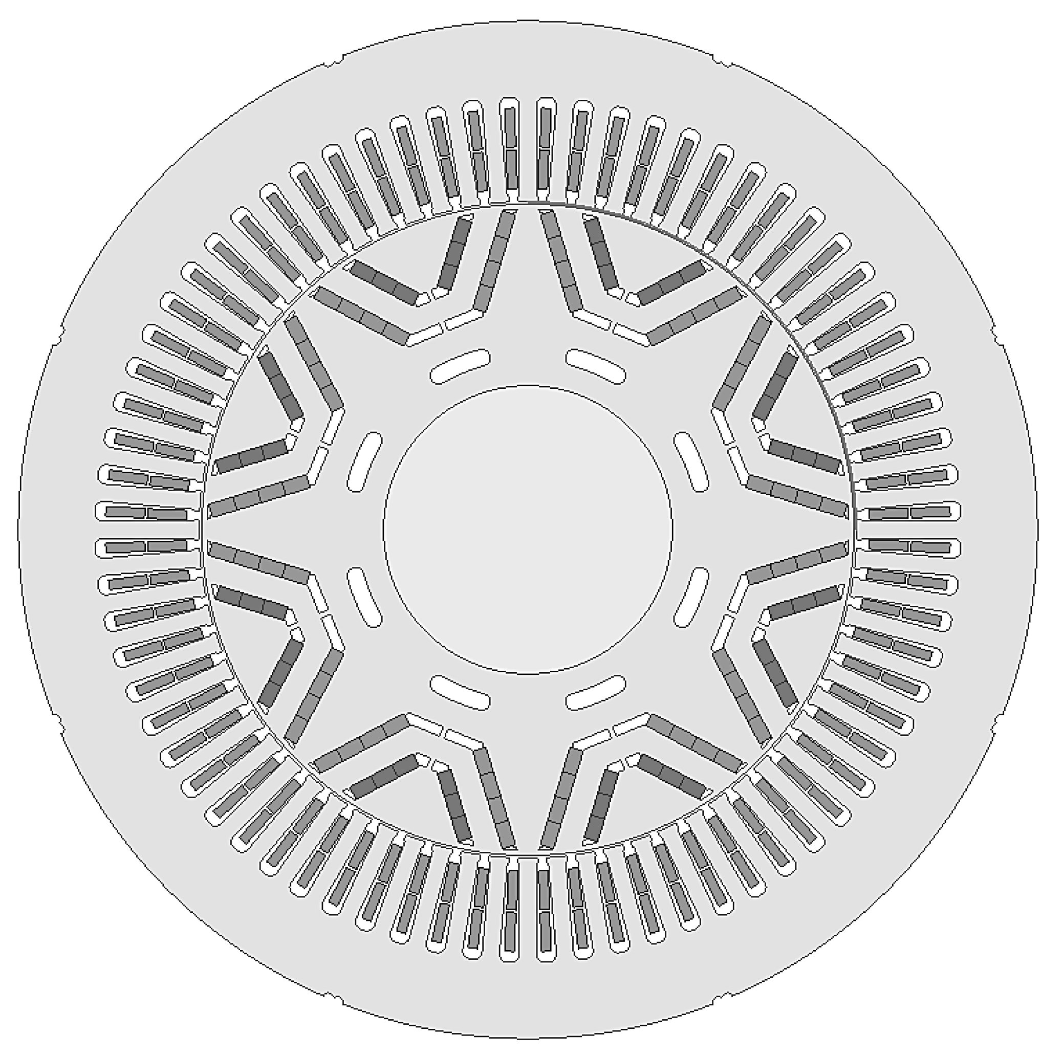
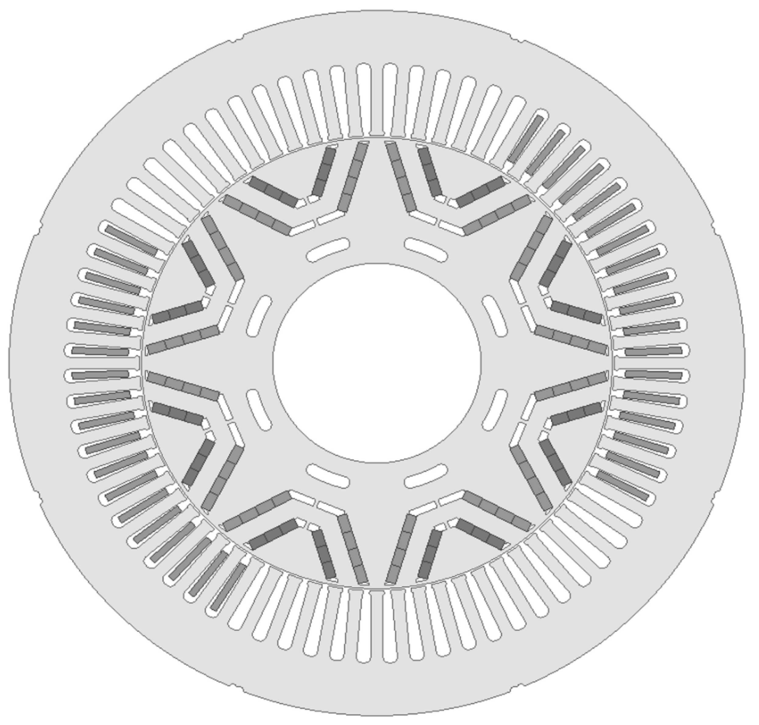
The analysis target is an eight-pole, 72-slot IPMSM, as shown in
Figure 1, with 3 equivalent slots per pole.
Table 1 presents the specifications of the analysis model. The maximum torque is 1200 Nm, and the operating speed ranges from a base speed of 1500 rpm to a maximum speed of 5000 rpm. The maximum output power is 190 kW. The stator winding is a concentric winding with eight parallel circuits, and the maximum applied current is 750 Arms.
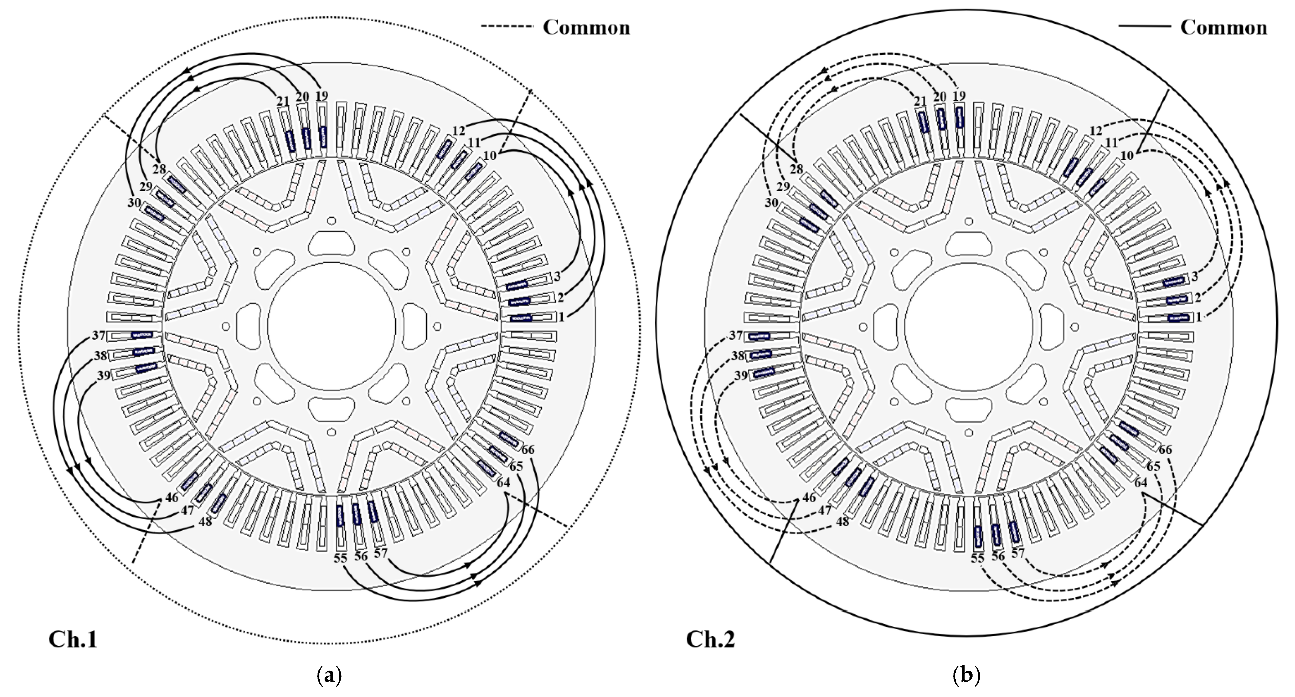
Figure 2 shows the initial winding configuration of the analysis model, where (a) represents the winding diagram for Ch.1, and (b) represents the winding diagram for Ch.2.
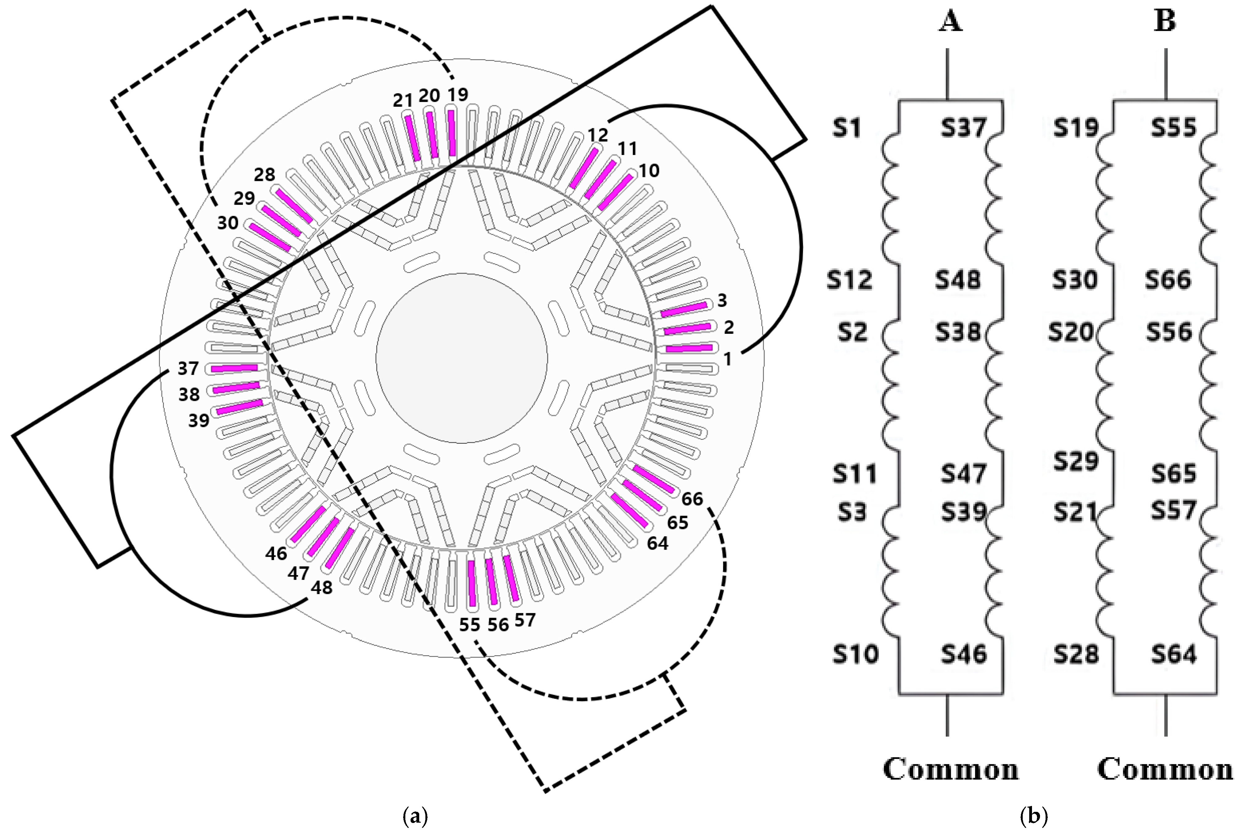
Figure 3 illustrates the initial planar winding diagram of the analysis model. It shows that a parallel circuit is fastened to one inverter through one terminal.
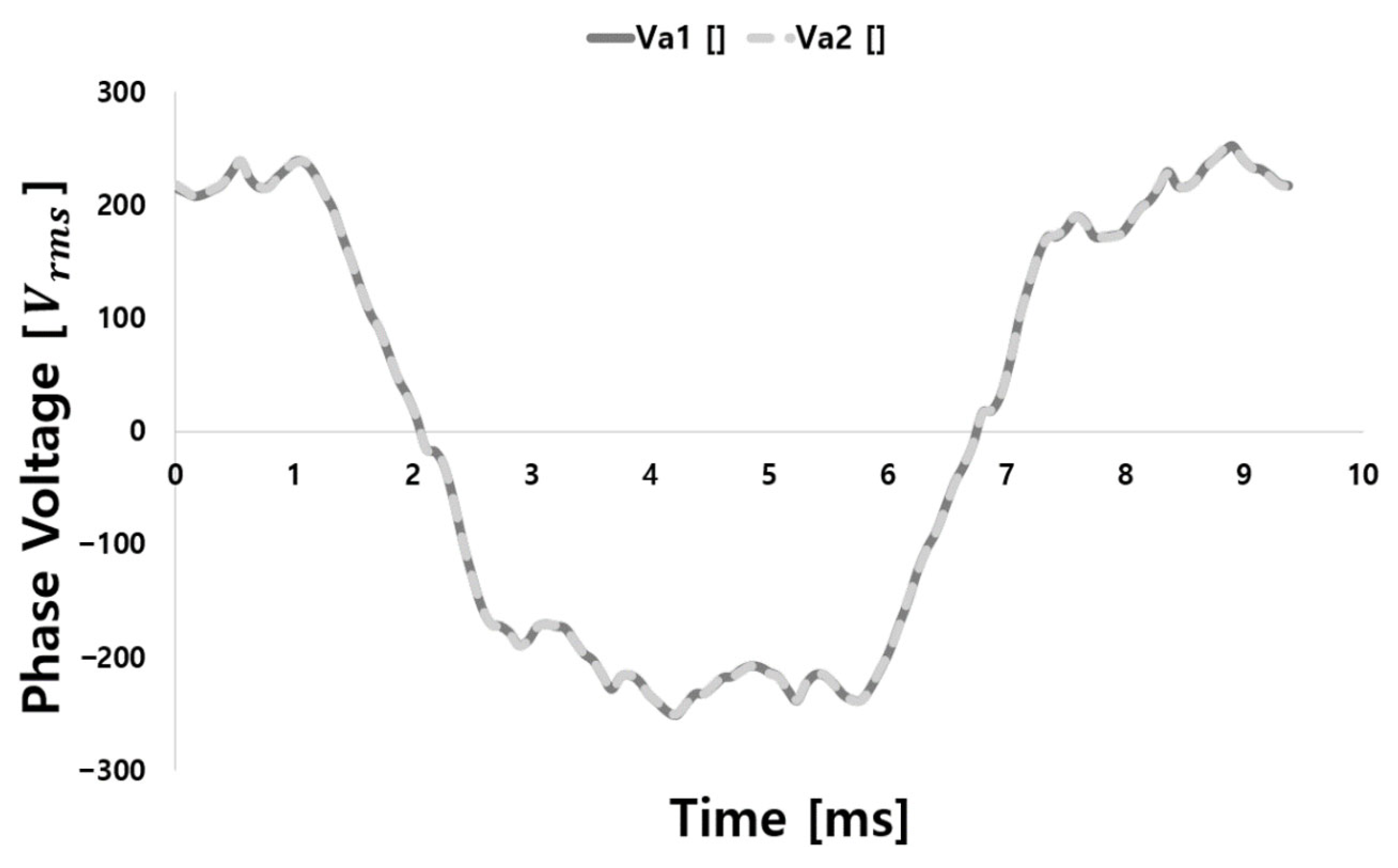
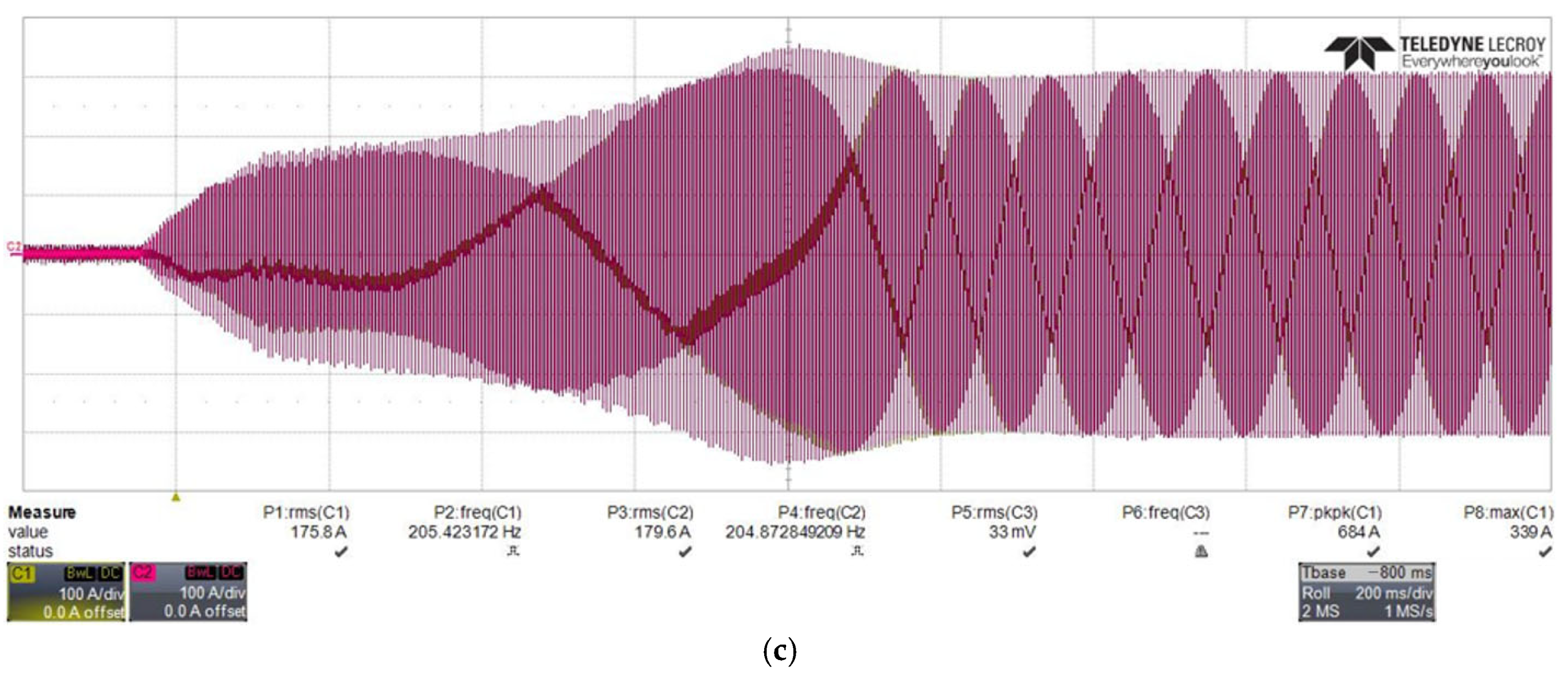
The dynamometer test results of the initial analysis model presented in
Figure 4 show voltage imbalance caused by inter-channel asymmetry. U1 is 106.01 V, and V1 is 102.44 V, resulting in a phase-to-phase voltage difference of 3.57 V. The unit is RMS phase voltage. The conditions that caused this imbalance were analyzed using a two-dimensional finite element method (FEM). To investigate the assumption of a phase difference between channel currents, a current phase difference condition was applied. The analysis confirmed that applying a current phase difference condition resulted in the same voltage imbalance as observed in the dynamometer experiment. When an inter-channel imbalance occurs, it leads to an uneven power distribution between the channel inverters. If excessive current flows through a specific part of the motor, it can result in overheating due to increased copper losses, ultimately causing insulation breakdown and damage to the motor. Furthermore, the occurrence of inter-channel imbalance can degrade inverter control performance, leading to instability in speed and torque control, which negatively affects the motor’s operational stability and performance. Therefore, compensating for inter-channel imbalance is essential to ensure stable motor operation and precise control [
5,
6].
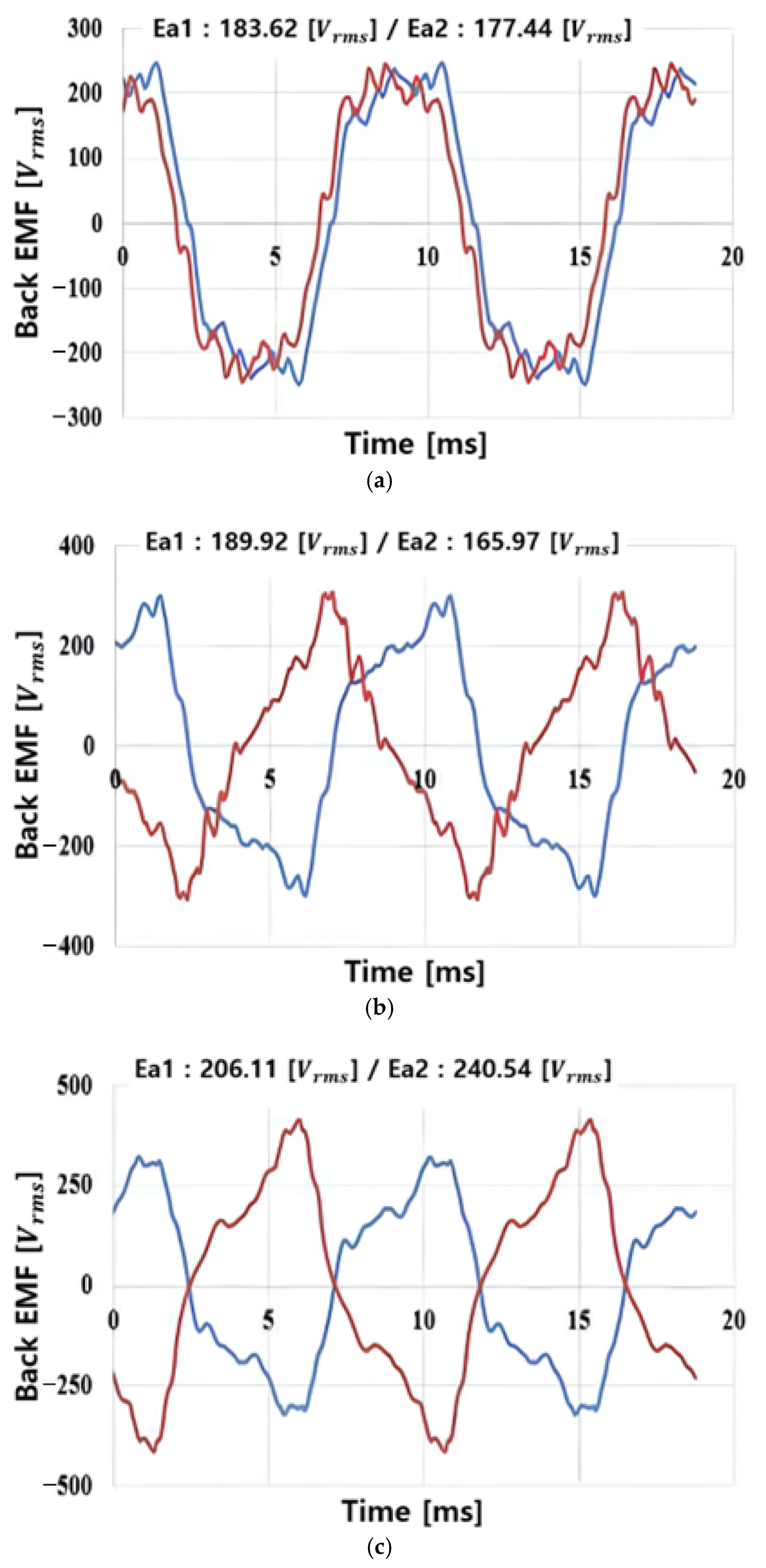
To identify the cause of the phase imbalance, the back electromotive force (EMF) was analyzed for three different cases of phase angle differences, as shown in
Figure 5. It was confirmed that a phase voltage imbalance occurs when there is a phase difference, and the larger the phase difference, the greater the phase-to-phase voltage difference. Even though the windings are coiled, if a difference in no-load back EMF between phases occurs, it can lead to an imbalance in the currents flowing between phases under load, which may result in a torque imbalance.
2.2. Improvement Analysis
Figure 6 shows the winding configuration applied to compensate for inter-channel imbalance. The initial design with eight parallel circuits was modified to four parallel circuits. Since the IPMSM contains permanent magnets inside the rotor, flux distribution is crucial. Theoretically, the amount of magnetic flux emerging from the N pole of the rotor should be equal to the amount entering the S pole. However, due to the magnetic circuit, this balance may not be maintained in practice, potentially leading to back EMF differences and resulting in imbalance. Therefore, the original configuration with eight parallel circuits—equal to the number of poles—was modified to four parallel circuits based on the number of pole pairs. In addition, reducing the number of stator parallel circuits facilitates more uniform current distribution among the parallel windings. Since each channel is controlled by a separate inverter, reducing the number of parallel circuits helps minimize the possible cases of current imbalance in terms of control performance. In
Figure 6a, the solid-lined phases are controlled by Channel 1 (Inverter 1), while the dotted-lined phases are controlled by Channel 2 (Inverter 2). In conventional motors, control is typically achieved using a single inverter. However, in the improved analysis model, due to the large current required to generate high torque, the winding is divided into two channels. This twin inverter system is used to reduce the current burden on the inverter switching devices [
7,
8,
9]. The circuit diagram in
Figure 6b shows that the stator winding has been modified from the original eight-parallel configuration to a four-parallel configuration to prevent current imbalance, and that a twin inverter system has been applied.
The voltage imbalance observed in the dynamometer experiment and FEM analysis of the initial model with an eight-parallel winding configuration was improved in the case of the four-parallel winding, as shown in the FEM analysis in
Figure 7, where the voltage of each phase was uniformly 120 Vrms [
10,
11].
2.3. Electromagnetic Field Characteristics in Case of Inverter Fault
In the scenario where one of the two channels in the motor’s twin inverter system fails to operate—meaning one of the two inverters is faulty and unable to supply power to the motor—it can be implemented by assuming the absence of windings, as shown in
Figure 8. Although the windings physically exist, they are considered to be open-circuited under the inverter fault condition, meaning no current flows through them. Theoretically, while the rotor of the motor has eight poles, the stator’s rotating magnetic field forms four poles under these conditions. As a result, synchronization between the rotor and the stator’s magnetic field cannot be achieved, preventing the motor from operating normally [
12,
13,
14].
Figure 9a,b show the flux density distribution and flux lines, respectively, at the maximum load operating point of the motor. The inverter control process remains the same as before the channel failure, with power supplied to only the remaining operational inverter. When power is supplied to only one inverter due to failure, it is equivalent to having no current flowing through half of the windings. In this case, flux is generated only in the windings carrying current, resulting in an asymmetric flux distribution within the motor. This imbalance disrupts the magnetic flux path between the rotor and stator, leading to an uneven torque generation in the motor. Consequently, the rotor’s rotation becomes unstable, and the overall performance of the motor deteriorates. Furthermore, the unbalanced flux can introduce adverse effects such as increased motor vibration and noise, potentially leading to further operational issues. As shown in
Table 2, torque decreases and torque ripple increases under the fault condition.
Figure 10a,b show the torque and voltage waveforms during normal inverter operation and inverter failure. When power is supplied to only one channel due to an inverter failure, the imbalance in flux distribution negatively impacts the characteristics, resulting in performance values being reduced to approximately half of those under healthy operating conditions. A comparison of characteristics at the maximum load operating point shows that the torque during normal operation is 1200 Nm, whereas in the event of an inverter failure, the torque decreases by 55.67% of the healthy torque. Additionally, torque ripple increases by 16.38%, indicating performance degradation. These results demonstrate that in the event of an inverter failure, the output decreases to less than half, and the torque ripple, which can cause noise and vibration, increases. However, on a positive note, the twin inverter system allows the motor to continue operating at a lower power level using the remaining functional inverter, ensuring continued operation even in the event of a failure [
15,
16,
17].
2.4. Attribute Analysis with Fault Condition
To improve current imbalance, an enhanced stator winding design was implemented. However, a phase difference may still occur due to variations in current offset values during inverter control, leading to inter-channel imbalance. In the twin inverter system, the control command that was previously applied to a single inverter must now be distributed between two inverters, making the system highly sensitive to the selected offset values of each inverter.
Figure 11 shows the current waveforms for each channel under different current offset conditions: (a) with an offset of 0, (b) with an offset of −0.015, and (c) with an offset of +0.03. By analyzing the current waveforms applied to each channel under these offset conditions, it was confirmed that the green region—where the waveforms of the channel currents do not match—was the smallest when the offset value was +0.03.
Table 3 presents the fault condition cases analyzed for inter-channel imbalance. Channel 1 was set to healthy operating conditions, while Channel 2 was subjected to current and phase imbalance conditions. In practice, when such current imbalance conditions occur, additional issues may arise, including changes in electromagnetic characteristics, insulation breakdown due to localized increases in copper loss, and irreversible demagnetization of permanent magnets caused by fluctuations in current magnitude or phase angle [
18,
19].
Figure 12 shows the voltage waveforms generated in each channel under the imbalance conditions specified in
Table 3. Each case was analyzed at two key operating points within the maximum output region: the base speed and the maximum speed. At the base speed, a large current is applied, while at the maximum speed, field-weakening control is significantly affected by the current phase angle. Therefore, by analyzing these two points, it is possible to infer the characteristics of inter-channel voltage differences across the entire maximum output region. In Case 1, where a current imbalance of +10 A was applied, the difference in back electromotive force (EMF) between channels was 1.11 Vrms at the base speed and 14.15 Vrms at the maximum speed. In Case 2, with a current imbalance of −10 A, the back EMF difference between channels was 1.12 Vrms at the base speed and 13.07 Vrms at the maximum speed. For Case 3, under a phase angle imbalance of +5 degrees, the back EMF difference between channels was 5.1 Vrms at the base speed and 142.33 Vrms at the maximum speed. Similarly, in Case 4, with a phase angle imbalance of −5 degrees, the back EMF difference between channels was 5.1 Vrms at the base speed and 142.33 Vrms at the maximum speed. In Case 5, where a current imbalance of +10 A and a phase angle imbalance of −5 degrees were applied, the back EMF difference between channels was 3.83 Vrms at the base speed and 126.92 Vrms at the maximum speed. These results indicate that phase angle differences between channels have a significant impact on the system’s characteristics when imbalance occurs. Therefore, high phase control accuracy is essential to ensure stable operation [
20,
21,
22].
3. Conclusions
This paper investigates the electromagnetic characteristics of an interior permanent magnet synchronous motor (IPMSM) used for electric vehicle traction under various control imbalance conditions, assuming a scenario in which one of the inverters in a twin inverter system fails to operate properly. While conventional traction motors have primarily been driven by single inverters, advancements in technology have led to the adoption of high-voltage and high-current systems, necessitating the use of twin inverter systems for stable operation. To ensure the reliability of twin inverter systems, this study considers a wide range of fault scenarios—from minor control mismatches to the complete failure of one inverter. Prior to that, under the single inverter condition, it was confirmed that applying an eight-parallel winding configuration to the stator caused phase voltage imbalance. By adjusting the number of parallel circuits to match the number of pole pairs, the voltage imbalance was eliminated. Based on these results, a twin inverter system was implemented with an appropriate number of stator parallel circuits per inverter. Electromagnetic characteristics were then analyzed under control imbalance conditions within the twin inverter configuration, including inverter control offset, inter-channel differences in current magnitude and phase, and the complete shutdown of one inverter. Through analysis of the applied current waveforms based on current offset values between channels using a dynamometer, an optimal offset value was identified that makes the current waveforms between channels closely match. In addition, the simulation results confirmed that when one inverter is completely failed and removed, the motor can still operate at approximately half of its normal performance. Finally, by applying various current magnitude and phase angle imbalance conditions between channels in both the base speed and max speed regions, each case was analyzed using simulations. The voltage waveforms and electromagnetic characteristics of each channel were examined, and the importance of the phase angle parameter was highlighted accordingly. Both FEM simulations and dynamometer tests were conducted to evaluate the resulting electromagnetic behavior. These results provide an intuitive understanding of how each type of control imbalance affects the motor’s performance and highlight the importance of balanced control and system-level stability in twin inverter applications.
Author Contributions
Conceptualization, J.-G.S. and H.-J.J.; data curation, J.-G.S. and T.-S.K.; formal analysis, H.-J.J.; investigation, J.-G.S. and T.-S.K.; supervision, K.-C.K.; writing—original draft, J.-G.S. and H.-J.J.; writing—review and editing, K.-C.K. All authors have read and agreed to the published version of the manuscript.
Funding
This work was supported by the Technology Innovation Program (K_G01200183304, Development of WFSM drive unit technology for complete exclusion of rare earths magnet) funded by the Ministry of Trade, Industry & Energy (MOTIE, Republic of Korea).
Data Availability Statement
The original contributions presented in this study are included in the article. Further inquiries can be directed to the corresponding author.
Conflicts of Interest
Author Hong-Jae Jang was employed by the Daewon Kang Up Co., Ltd. The remaining authors declare that the research was conducted in the absence of any commercial or financial relationships that could be construed as a potential conflict of interest.
References
- Kalaiselvi, J.; Srinivas, S. Hybrid PWMs for shaft voltage reduction in a dual inverter fed induction motor drive. In Proceedings of the 2013 IEEE International Conference on Industrial Technology (ICIT), Cape Town, South Africa, 25–28 February 2013; pp. 539–544. [Google Scholar]
- Matsumori, H.; Makimura, Y.; Morisita, S.; Maeda, Y.; Kosaka, T.; Matsui, N.; Saito, N.; Ito, Y.; Saha, S. Optimum PWM switching mode selection of dual inverter-fed open winding IPMSM drive system for high-power premium class EV. In Proceedings of the 2020 IEEE Energy Conversion Congress and Exposition (ECCE), Detroit, MI, USA, 11–15 October 2020; pp. 6318–6324. [Google Scholar]
- Kim, K.-C. A novel magnetic flux weakening method of permanent magnet synchronous motor for electric vehicles. IEEE Trans. Magn. 2012, 48, 4042–4045. [Google Scholar] [CrossRef]
- Sue, S.-M.; Pan, C.-T. Voltage-constraint-tracking-based field-weakening control of IPM synchronous motor drives. IEEE Trans. Ind. Electron. 2008, 55, 340–347. [Google Scholar] [CrossRef]
- Kadota, M.; Lerdudomsak, S.; Doki, S.; Okuma, S. A novel current control system of IPMSM operating at high speed based on model predictive control. In Proceedings of the 2007 Power Conversion Conference—Nagoya, Nagoya, Japan, 2–5 April 2007; pp. 1315–1319. [Google Scholar]
- Ji, S.-H.; Lee, J.-K.; Jang, K.-B.; Kim, G.-T. Torque calculation and experiment of IPMSM by current phase angle control. In Proceedings of the 2011 KIEE Conference, Gwangju, Republic of Korea, 20 October 2011; pp. 71–74. [Google Scholar]
- Hong, I.-P.; Yoo, J.-Y. Field weakening control of IPMSM by current phase angle control. In Proceedings of the Power Electronics Conference, Gyeonggi, Republic of Korea, 31 October 2008; pp. 19–21. [Google Scholar]
- Nam, T.-H.; Kim, M.-S.; Kwon, Y.-J.; Jeong, D.-H.; Cheo, D.-S.; Hwang, Y.-H.; Jung, S.-Y. Design to improve efficiency and torque ripple through rotor shape design of IPMSM for electric vehicle. In Proceedings of the 2023 KIEE Conference, Chungbuk, Republic of Korea, 19 October 2023. [Google Scholar]
- Lee, S.-W.; Kang, J.-K.; Kim, S.-H.; Hur, J. IPMSM fault diagnosis method using variable reluctance resolver. Trans. Korean Inst. Electr. Eng. 2024, 73, 523–530. [Google Scholar] [CrossRef]
- Ibrahim, M.; Rjabtšikov, V. EV-permanent magnet synchronous motor control strategy evaluation based on digital twin concept. In Proceedings of the 2023 IEEE 17th International Conference on Compatibility, Power Electronics and Power Engineering (CPE-POWERENG), Tallinn, Estonia, 20–23 June 2023; pp. 1–5. [Google Scholar]
- Kim, J.-G.; Park, Y.-J.; Lee, E.-W. Analysis on the characteristics of voltage unbalance factor by load variations. Trans. Korean Inst. Electr. Eng. 2005, 54P, 47–52. [Google Scholar]
- Shim, J.-H.; Choi, H.-G.; Ha, J.-I. PWM variable carrier generating method for OEW PMSM with dual inverter and current ripple analysis according to zero vector position. Trans. Korean Inst. Power Electron. 2020, 25, 279–285. [Google Scholar]
- Kim, S.-A.; Hong, K.-P. Development of average model to analyze dynamic characteristics of variable speed driven turbo air compressor system with multi-level inverter. Trans. Korean Inst. Electr. Eng. 2020, 69, 1200–1207. [Google Scholar] [CrossRef]
- Kim, J.-G.; Park, Y.-J.; Lee, E.-W. Torque measurement of induction motor caused by voltage unbalance. In Proceedings of the KIEE Conference, Daejeon, Republic of Korea, 28-29 May 2004; pp. 101–104. [Google Scholar]
- Lee, C.-H.; Kim, C.-M.; Jang, H.-J.; Kim, T.-S.; Kim, K.-C. Analysis of whether motor can be operated according to poles/slot combination under conditions assuming failure. In Proceedings of the KIEE Conference, Chungbuk, Republic of Korea, 19–21 October 2023; pp. 78–79. [Google Scholar]
- Yoo, S.-M.; Shin, J.-W.; Lee, W.-S.; Hwang, S.-H. Operating characteristics analysis of asymmetric 6-phase permanent magnet synchronous motor by unbalanced dual inverter. In Proceedings of the KIEE Conference, Jeju, Republic of Korea, 6–8 May 2021; pp. 257–258. [Google Scholar]
- Santos, N.M.R.; Pires, V.; Silva, J.F. A dual inverter topology controlled by a voltage sliding mode in normal and fault operation. In Proceedings of the 9th International Conference on Compatibility and Power Electronics (CPE), Costa da Caparica, Portugal, 24–26 June 2015; pp. 346–351. [Google Scholar]
- Kwak, N.J.; Hwang, J.H.; Hong, W.P. Switch open fault diagnosis of inverter using features of dq currents. Inst. Electron. Eng. Korea Syst. Control 2011, 48, 31–38. [Google Scholar]
- Kimura, T.; Yamada, T.; Kazaoka, R.; Noguchi, T. Control Method of a Dual Inverter System for EV with One Battery. In Proceedings of the 2022 International Power Electronics Conference (IPEC-Himeji 2022- ECCE Asia), Himeji, Japan, 15–19 May 2022; pp. 31–38. [Google Scholar]
- Rodríguez, J.; Lai, J.S.; Peng, F.Z. Multilevel inverters: A survey of topologies, controls, and applications. IEEE Trans. Ind. Electron. 2002, 49, 724–738. [Google Scholar] [CrossRef]
- Kim, J.; Jung, J.; Nam, K. Dual-inverter control strategy for high-speed operation of EV induction motors. IEEE Trans. Ind. Electron. 2004, 51, 312–320. [Google Scholar] [CrossRef]
- Jang, H.-J.; Kim, C.-M.; Lee, C.-H.; Kim, T.-S.; Shin, J.-K.; Kim, K.-C. Study on the Electromagnetic Characteristics of a Twin Inverter System EV Traction Motor under Various Operating Conditions. In Proceedings of the 2024 IEEE 21st Biennial Conference on Electromagnetic Field Computation (CEFC), Jeju, Republic of Korea, 14–17 May 2024. [Google Scholar]
Figure 1.
Analysis model.
Figure 1.
Analysis model.
Figure 2.
Initial connection of the analysis model: (a) Ch.1, (b) Ch.2.
Figure 2.
Initial connection of the analysis model: (a) Ch.1, (b) Ch.2.
Figure 3.
Initial planar winding connection diagram of the analysis model.
Figure 3.
Initial planar winding connection diagram of the analysis model.
Figure 4.
Dynamometer test waveform to channel current imbalance.
Figure 4.
Dynamometer test waveform to channel current imbalance.
Figure 5.
Back electromotive force analysis according to phase difference: (a) 20-degree phase difference, (b) 40-degree phase difference, (c) 90-degree phase difference.
Figure 5.
Back electromotive force analysis according to phase difference: (a) 20-degree phase difference, (b) 40-degree phase difference, (c) 90-degree phase difference.
Figure 6.
Improvement model: (a) 2D winding, (b) winding connection diagram.
Figure 6.
Improvement model: (a) 2D winding, (b) winding connection diagram.
Figure 7.
Improvement model phase voltage.
Figure 7.
Improvement model phase voltage.
Figure 8.
In case of Channel 2 fault, the assumed 2D-FEM analysis model.
Figure 8.
In case of Channel 2 fault, the assumed 2D-FEM analysis model.
Figure 9.
Field distribution in case of Channel 2 fault: (a) flux density, (b) flux line.
Figure 9.
Field distribution in case of Channel 2 fault: (a) flux density, (b) flux line.
Figure 10.
Comparison of operating characteristics in healthy and fault conditions: (a) torque, (b) voltage.
Figure 10.
Comparison of operating characteristics in healthy and fault conditions: (a) torque, (b) voltage.
Figure 11.
Inter-channel applied current waveform according to inverter offset value difference: (a) offset value: 0, (b) offset value: −0.015, (c) offset value: +0.03.
Figure 11.
Inter-channel applied current waveform according to inverter offset value difference: (a) offset value: 0, (b) offset value: −0.015, (c) offset value: +0.03.
Figure 12.
Fault condition assumption analysis results. (a) Case1, 2, 3; (b) Case4, 5.
Figure 12.
Fault condition assumption analysis results. (a) Case1, 2, 3; (b) Case4, 5.
Table 1.
Specifications of analysis model.
Table 1.
Specifications of analysis model.
| Parameter | Analysis Model | Unit |
|---|
| Number of poles/slots | 8/72 | - |
| Max. Torque | 1200 | Nm |
| Operation range (Base/Max) | 1500/5000 | rpm |
| Max. Power | 190 | kW |
| Parallel paths | 8 | - |
| Winding | Concentric | - |
| Max. Current | 750 | Arms |
Table 2.
Comparison of operating characteristics in healthy and fault conditions.
Table 2.
Comparison of operating characteristics in healthy and fault conditions.
| Parameter | Value | Unit |
|---|
| Healthy | Fault |
|---|
| Torque | 1198.38 | 531.22 | Nm |
| Torque Ripple | 7.64 | 24.02 | % |
| Phase Voltage | 120.30 | 135.03 | Vrms |
| Line Voltage | 205.32 | 183.03 | Vrms |
Table 3.
Case of fault condition.
Table 3.
Case of fault condition.
| Case | Parameter | Channel | Note |
|---|
| Channel 1 | Channel 2 |
|---|
| 1 | Current | Healthy condition | Channel 1 + 10 A | Current unbalanced assumptions |
| 2 | Current | Healthy condition | Channel—10 A | Current unbalanced assumptions |
| 3 | Current
angle | Healthy condition | Channel 1 + 5 deg | Phase unbalanced assumptions |
| 4 | Current
angle | Healthy condition | Channel 1—5 deg | Phase unbalanced assumptions |
| 5 | Current + Current
angle | Healthy condition | Channel 1 + 10 A
Channel 1 + 5 deg | Current and phase unbalanced assumptions |
| Disclaimer/Publisher’s Note: The statements, opinions and data contained in all publications are solely those of the individual author(s) and contributor(s) and not of MDPI and/or the editor(s). MDPI and/or the editor(s) disclaim responsibility for any injury to people or property resulting from any ideas, methods, instructions or products referred to in the content. |
© 2025 by the authors. Licensee MDPI, Basel, Switzerland. This article is an open access article distributed under the terms and conditions of the Creative Commons Attribution (CC BY) license (https://creativecommons.org/licenses/by/4.0/).


