1. Introduction
Thermal oil recovery methods operate by reducing oil viscosity through heat transfer, facilitating its mobilisation and production. These methods encompass steam flooding (both cyclic and continuous), electric heating, in situ combustion (ISC), and SAGD. These thermal methods each have distinct operational profiles. In situ combustion is thermally efficient as it generates heat within the reservoir but can be operationally complex and difficult to control. In situ combustion entails the injection of air into viscous oil formations, where a controlled fraction of the in-place oil is ignited to generate heat internally within the reservoir [
1]. Steam-based methods such as steam flooding and SAGD are highly effective at reducing oil viscosity but can be energy- and water-intensive with significant greenhouse gas emissions [
2]. In steam-based processes, the steam is injected into the reservoir to raise the temperature of the heavy oil or bitumen, thereby lowering its viscosity to a level that allows it to flow under the influence of gravity. Variants of steam-based recovery include steam flooding (SF), cyclic steam stimulation (CSS)—commonly known as “huff and puff”—and SAGD, each offering distinct operational advantages depending on reservoir characteristics and development strategy. In the SAGD process, this is achieved using two parallel horizontal wells. The upper well functions as the steam injector, delivering heat to the reservoir, whilst the lower well serves as the production well, collecting and extracting the mobilised oil [
2].
Steam injection, on the other hand, is typically employed in shallow, thick, and highly permeable heavy oil reservoirs to reduce oil viscosity and enhance flow [
3]. Variants of steam-based recovery include steam flooding (SF), cyclic steam stimulation (CSS)—commonly known as “huff and puff”—and steam-assisted gravity drainage (SAGD), each offering distinct operational advantages depending on reservoir characteristics and development strategy.
Soon after SAGD’s beginnings, new alternatives were sought to make it more efficient by increasing the oil recovery and/or decreasing the required resources for its implementation. Currently, under renewed environmental concerns for heavy oil exploitation, more stringent regulations demand less energy consumption and a reduction in greenhouse gas (GHG) emissions. Single-solvent coinjection has been studied in several evolving processes (LASER, ES-SAGD, SAGP, SAS, Solvent Injection with Hot Water) to combine the advantages of heat and solvent [
4] using numerical and experimental methods [
5,
6,
7,
8,
9,
10,
11,
12,
13,
14,
15,
16,
17,
18,
19,
20,
21,
22,
23], and some field tests have been implemented [
24,
25,
26].
In ES-SAGD, steam and solvent are coinjected using a typical SAGD well configuration to increase the mobility of highly viscous bitumen through combined heat and mass transfer effects [
27,
28,
29,
30]. The interrelated effects of heat transfer [
31], diffusion and dispersion, in addition to reservoir properties and operating conditions [
32], play essential roles in determining the appropriate solvent composition, concentration, and coinjection strategy that can be used to enhance the overall performance of SAGD.
The use of solvents to enhance SAGD performance requires a strong understanding of the roles of key parameters to achieve the most from this application. Some of these operational parameters, which require adjustments with variations in the reservoir properties, are steam-bitumen/rock heat transfer, solvent-bitumen mass transfer, solvent type, solvent concentration, steam temperature, and injection pressure to maximise oil recovery and minimise energy consumption [
33]. One aspect of the solvent-assisted SAGD process that has not been adequately investigated is the effect of solvents on residual oil saturation that is directly linked to the recovery factor [
33]. In that study, pentane and hexane were coinjected with steam in SAGD experiments using Long Lake bitumen to determine their effects on residual oil saturation.
It is expected that the solvent will travel with steam in the vapour phase to the vapour chamber boundary, where both steam condensation and solvent dissolution in bitumen can be effective for mobilising bitumen [
6]. If the solvent exhibits too-heavy molar weight and/or is in too-high concentration, it will start condensing and draining down before reaching the chamber boundary, which will provide no benefit [
9]. Lighter solvents, such as pentane and hexane, showed promising results as potential solvents as these tend to be more soluble in bitumen and can potentially result in enhanced dilution if they can remain vaporised within the vapour chamber [
33].
The solvent vapour does not condense until the partial pressure of the solvent in the vapour is higher than its dewpoint pressure; however, it dissolves and diffuses into the oil. As the diluted oil drains, the steam chamber will continue growing, and a renewed interface with a lower solvent concentration will be exposed [
11]. Research on a Lloydminster heavy oil sample and methane, ethane, propane and carbon dioxide found that the interfacial tension was reduced almost linearly with pressure for these four oil-solvent systems at reservoir temperature [
34]. In agreement with other research [
35], it was suggested that the reduced interfacial tension alters the gravity-capillary force balance and thus reduces the residual oil saturation.
An experimental study coinjecting single-component solvent found that maximum oil drainage rates occurred when the steam temperature matched the solvent vaporisation temperature [
36]. In their study, the drainage rate improved with (1) the increasing carbon number of the injected solvent and (2) as the vaporisation temperature of the solvent became closer to the injected steam temperature.
To date, different research has tested the efficacy of the ES-SAGD process using single-component solvents, enhancing oil production rates and reducing the steam–oil ratio compared to conventional SAGD. Nevertheless, there has not been an experimental assessment of residual oil saturation to corroborate the data calculated using numerical methods. To achieve this goal, this study employs a linear sand pack to thoroughly investigate residual oil saturation under the ES-SAGD process. The experiments leverage Long Lake bitumen and replicate real operating conditions regarding pressure and temperature specific to this oilfield. This work represents a comprehensive experimental investigation aimed at adjusting the implementation of field pilots and ensuring effective in-house project planning.
2. Background Information on Expanding Solvent Steam-Assisted Gravity Drainage (ES-SAGD)
ES-SAGD was introduced as a hybrid process designed to enhance the efficiency of conventional SAGD whilst mitigating its limitations [
4]. This innovative approach leverages the synergistic effects of both steam and solvent to further reduce the viscosity of bitumen, thereby improving oil recovery rates.
In the ES-SAGD process, steam delivers thermal energy to the reservoir, effectively lowering the viscosity of bitumen. Simultaneously, a small quantity of solvent is coinjected in vapour form, which dissolves into the bitumen along the edges of the steam chamber, further enhancing viscosity reduction. An appropriate solvent or diluent selection is based on its phase behaviour, ensuring compatibility with the operating steam temperature under reservoir conditions [
36].
As the steam-solvent mixture forms a vapour chamber within the reservoir, it gradually expands, and both steam and solvent condense at the chamber’s boundaries upon contact with the surrounding cold bitumen [
13]. At this stage, viscosity reduction occurs through two primary mechanisms: the transfer of latent heat from the condensing steam and the diffusion of the condensed solvent into the bitumen, promoting dilution. This dual-action mechanism leads to a more significant viscosity reduction than conventional SAGD, facilitating faster and more efficient oil recovery.
Beyond enhancing oil production rates, ES-SAGD offers several advantages over traditional SAGD, including a lower cumulative steam-oil ratio (cSOR), reduced water consumption, and a decrease in greenhouse gas (GHG) emissions, making it a more energy-efficient and environmentally sustainable recovery method [
18].
2.1. Viscosity Reduction by Heat Transfer, Diffusion and Dispersion of Solvent
Beyond enhancing oil production rates, ES-SAGD offers several advantages over traditional SAGD, including a lower cSOR, reduced water consumption, and a decrease in greenhouse gas (GHG) emissions, making it a more energy-efficient and environmentally sustainable recovery method [
2]. As the steam-solvent mixture enters the vapour chamber, it migrates towards the chamber boundary, where both components undergo phase transitions. The steam condenses, releasing its latent heat to mobilise the bitumen, whilst the solvent dissolves and diffuses into the bitumen, further reducing its viscosity [
14]. Under specific phase behaviour conditions, a secondary hydrocarbon liquid phase may form at the vapour chamber boundary [
4]. A critical objective of the ES-SAGD process is to maximise solvent recovery for recycling and reinjection. Minimising solvent losses to the surrounding oil sands and formations is essential, as the injected solvent as a refined oil product, is considerably more costly than the produced bitumen [
9].
During solvent injection into heavy oil reservoirs, the interaction between the injected solvent and the heavy oil can lead to asphaltene precipitation, depending on the solvent type, pressure, and temperature conditions [
37]. Asphaltenes are insoluble in straight-chain alkanes ranging from propane (C
3) to n-decane (C
10), as well as in certain incompatible fluids such as CO
2, which promotes their precipitation [
38]. The extent of asphaltene deposition is inversely related to the alkane chain length, with shorter-chain alkanes inducing greater precipitation [
39]. In solvent-based recovery processes, asphaltene precipitation can be beneficial by reducing the viscosity of the produced heavy oil and enhancing its quality [
40]. However, excessive asphaltene precipitation may result in pore blockage and a decline in system permeability, ultimately impairing hydrocarbon mobility and causing formation damage [
41].
2.2. Solvent Selection
The integration of solvents with steam for bitumen recovery has been a subject of extensive research, with early investigations highlighting the influence of solvent type, concentration, and application method on process efficiency.
Pioneered studies on solvent-assisted bitumen recovery from oil sands demonstrate that the effectiveness of the process is highly dependent on the choice of solvent, the quantity used, and the technique of solvent introduction [
42]. Their findings laid the groundwork for subsequent research into optimising solvent–steam interactions for enhanced bitumen mobilisation.
Building upon these insights, another research explored the potential of hydrocarbon additives in conjunction with low-pressure steam, whilst also assessing possible adverse effects [
43]. Their experimental investigations spanned a range of hydrocarbons, from methane to synthetic crude oil. The study revealed that higher molecular weight hydrocarbon mixtures could significantly improve bitumen recovery, provided they contained sufficient light components to sustain the necessary drive energy. However, this enhancement came at the cost of increased hydrocarbon retention within the formation, raising concerns regarding solvent losses.
Nasr et al. [
36] proposed the use of hexane or higher-carbon-number diluents for the ES-SAGD process. Their study highlighted that the most effective solvent is one whose thermodynamic properties closely resemble those of water at the prevailing temperature and pressure conditions within the steam chamber.
McCormack [
44] conducted a numerical investigation on the impact of hexane coinjection with steam in a SAGD process. The findings demonstrated that ES-SAGD, with hexane addition, not only enhances oil recovery but also reduces energy requirements compared to conventional SAGD.
Further research by Nourozieh [
45] revealed that lighter hydrocarbons are more effective than heavier hydrocarbons in lowering oil density. This is attributed to the smaller molecular size of lighter hydrocarbons, which results in a greater number of molecules per unit weight composition (wt%), thereby facilitating improved oil dilution and viscosity reduction.
The literature suggests several key screening criteria for selecting an appropriate solvent for ES-SAGD. The most effective solvent is one whose thermodynamic properties closely resemble those of water at the prevailing steam chamber conditions. Lighter hydrocarbons are noted for their effectiveness in lowering oil density due to their smaller molecular size, which enhances dilution. It is also critical that the solvent remains in the vapour phase to ensure proper distribution within the chamber. However, this must be balanced against findings that show higher molecular weight solvents can improve bitumen recovery, though they come with a greater risk of being retained in the formation.
2.3. Single Solvent ES-SAGD Field Applications and Experimental Investigations
In ES-SAGD, a solvent or solvent mixture is coinjected with steam within a SAGD well configuration to enhance oil recovery. Given that solvent/steam mixtures are more expensive than steam alone, assessing the impact of solvent type and concentration on SAGD performance is critical [
46]. To address this, an extensive simulation study was conducted using a two-dimensional reservoir model representative of typical Athabasca rock and fluid properties. The study provided a detailed evaluation of drainage mechanisms, offering insights into optimising solvent coinjection strategies to maximise production whilst minimising energy consumption [
47].
Hele-Shaw cell experiments conducted with Peace River, Cold Lake, and Lloydminster oils have demonstrated that propane injection near its saturated vapour pressure induces deasphalting. This phenomenon does not hinder the flow of diluted oil, as asphaltenes occupy less than 20% of the pore space, allowing propane vapour to bypass them and interact with the remaining heavy oil. Consequently, continuous deasphalting further reduces viscosity and enhances oil mobility [
48].
Two-dimensional physical model tests using saturated propane with Lloydminster heavy oil at an initial temperature of 20 °C revealed that the optimal extraction rates occur at operating pressures between 846 and 915 kPa. However, at higher propane pressures, excessive asphaltene precipitation impairs drainage flow. Additionally, bench-scale mixing experiments demonstrated that propane significantly reduces the viscosity of Lloydminster and Cold Lake heavy oils by factors of 50 and 300, respectively [
49].
Qualitative experiments using Hele-Shaw cells and packed beds indicate that in situ upgrading and deasphalting are less pronounced when butane is used as a solvent compared to propane. Specifically, butane at its dew point does not induce deasphalting in Peace River oil at 25 °C and only causes minimal asphaltene precipitation in Lloydminster oil at 20 °C. However, a more extensive pattern of asphaltene deposition was observed in Peace River oil when saturated butane was used at 30 °C. Hele-Shaw cell experiments suggest that propane yields approximately 2.5 times the production rate of higher-quality oil compared to butane [
50].
Imperial Oil of Canada investigated the integration of liquid additives (C5+) into cyclic steam stimulation (CSS) under the process known as LASER (“Liquid Addition to Steam for Enhancing Recovery”). Encouraged by promising findings from physical experiments [
51], a pilot test was launched in Cold Lake in August 2002 [
52]. The pilot demonstrated enhanced bitumen recovery with the introduction of a diluent, with a notably high recovery rate of approximately 80% during the first operational cycle. A substantial portion of the recovered diluent was captured from venting facilities, significantly improving the project’s economic feasibility.
Despite this, the butane extraction process (BUTEX) offers an economically viable approach for heavy oil production whilst reducing the risk of reservoir plugging [
53]. EnCana conducted a field pilot test of a solvent-aided process utilising butane, which resulted in a 2.5-fold increase in production rates over six months and a notable improvement in oil quality [
54].
Nexen conducted an ES-SAGD pilot test at the Long Lake site from 13 February to 16 April 2006. During this trial, heavy hydrocarbon fractions (ranging from C7 to C12) were coinjected with steam at an initial concentration of 10%. This concentration was subsequently reduced to 5% to maintain an optimal solvent ratio within the steam chamber. However, after two months of operation, no noticeable increase in bitumen production was observed, leading to the termination of the test [
55].
EnCana conducted an ES-SAGD field test at Senlac, aiming to enhance SAGD performance through butane coinjection as the selected solvent. However, the test was discontinued after two months due to a loss of reservoir containment. Despite this, the process demonstrated a 50% increase in bitumen production and over 70% recovery from the well pair. Another contributing factor to the test’s termination was the unintended mixing of recovered butane with the produced gas, which was subsequently combusted in the boilers [
55].
In 2004, EnCana initiated another ES-SAGD project at Christina Lake. This trial yielded promising results, as the steam-oil ratio (SOR) was significantly reduced from 5 to 1.6, whilst the oil drainage rate increased from 167 m
3/day to 240 m
3/day [
55].
Field implementations have primarily focused on key performance indicators (KPIs) such as solvent recovery—driven by both the economic implications of solvent cost and the feasibility of reinjection—reduction in the steam-oil ratio (SOR), and improvement in RF. According to published literature, the outcomes of these applications are generally positive and encouraging, although they exhibit variability [
33]. However, micro-scale phenomena, including mineralogical interactions, remain largely unexplored, and critical aspects such as asphaltene segregation are yet to be fully understood.
While a detailed quantitative economic analysis is beyond the scope of this experimental study, the economic viability of any ES-SAGD process is a critical consideration. Key economic drivers identified in the literature include the cost of the injected solvent relative to the price of produced bitumen, the efficiency of solvent recovery for reinjection, and the overall reduction in the steam-oil ratio (SOR), which lowers operational energy costs.
3. Experimental Equipment and Procedures
3.1. Setup Design Features for Efficiency
Due to the critical impact of heat loss and steam condensation in SAGD-type core flooding experiments, several design and operational strategies were implemented to mitigate thermal inefficiencies throughout the setup:
Insulation of the sand pack: The sand pack assembly was wrapped in a layer of thermal insulation to minimise conductive heat loss through the metal housing during the experiment. After the thermocouples’ installation, another insulation layer was added.
Minimising heat loss in steam and solvent delivery: The steam generator and steam and solvent lines were positioned close to the sand pack holder to reduce the length of steam transport. It was housed within a thermally insulated enclosure, and the connecting tubing was wrapped with insulation material and equipped with a heating tape to preserve steam temperature.
Preheating the sand pack: The lower section of the sand pack was preheated to 70 °C before steam injection, replicating initial well conditions, facilitating the establishment of a thermal connection between the injector and producer well, and aiding in initial bitumen mobilisation.
Insulating the injection and production lines reduced potential plugging and intermittent flow by maintaining high fluid temperatures.
Temperature monitoring: Two thermocouples were installed—one at the outlet of the steam generator and another at the injection port of the sand pack—to continuously monitor and ensure thermal integrity from generation to injection. A third thermocouple was installed at the sand pack outlet.
Steam stabilisation: Steam was pre-circulated, bypassing the sand pack until reaching the injection conditions to achieve thermal equilibrium within the injector and steam generator before the onset of testing.
3.2. Experimental Setup
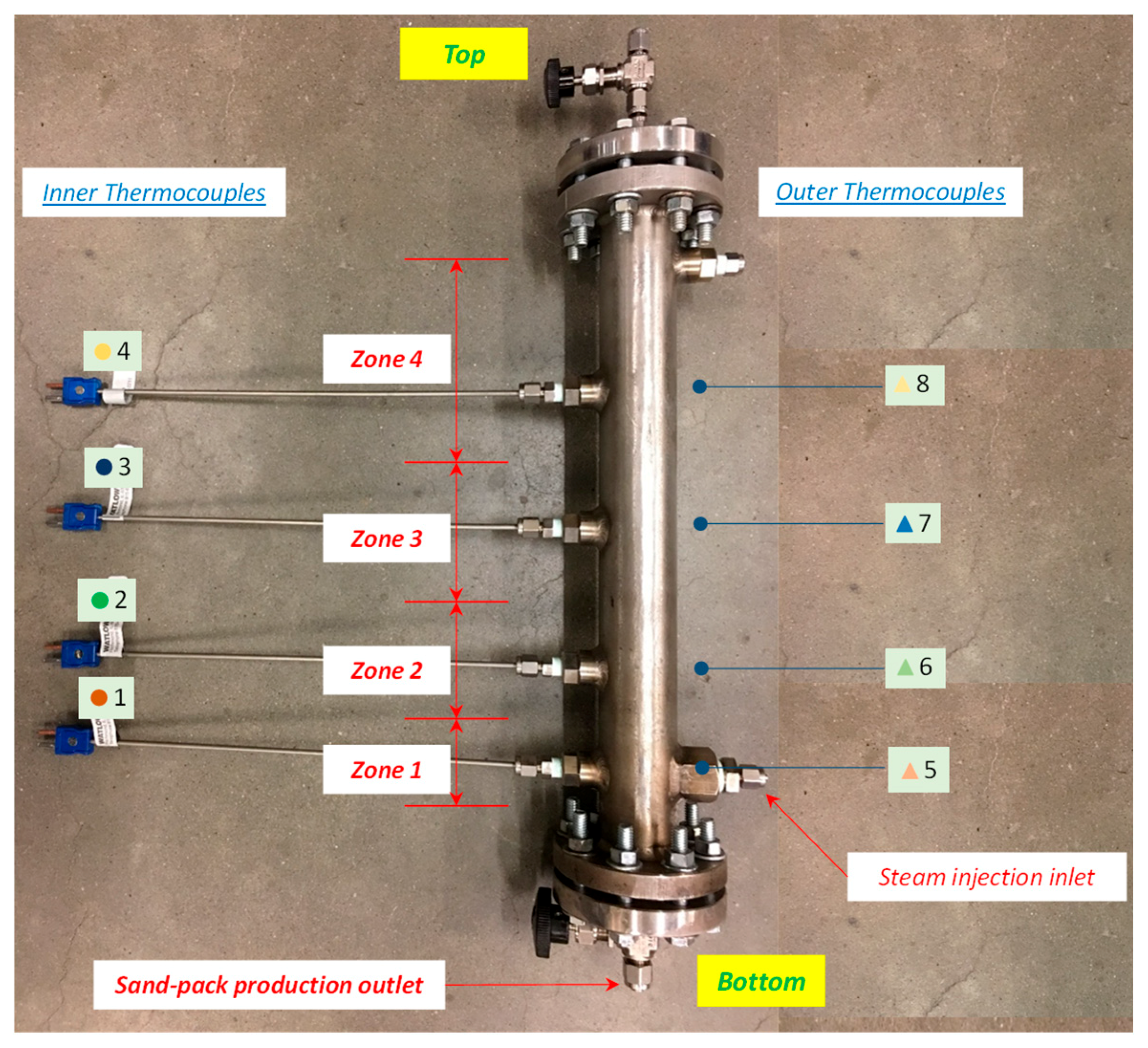
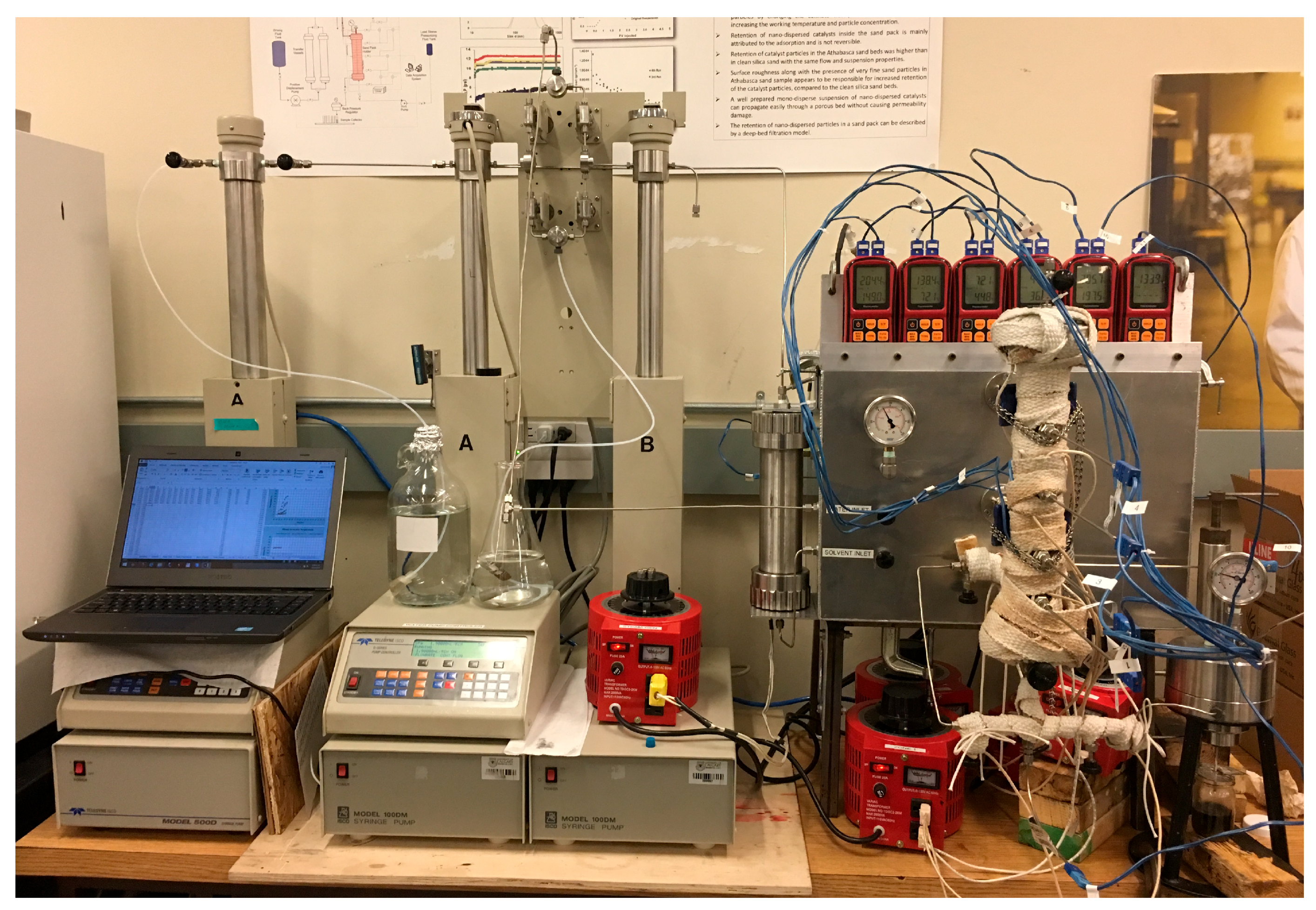
A physical sand pack model (31.6 cm length and 2.54 cm inner diameter), which was able to operate at temperatures and pressure conditions of the SAGD operation in the Long Lake field (207 °C and 230 psi), was constructed. This model was utilised to evaluate the effect of solvent and steam coinjection on the residual oil saturation remaining in the sand pack after the SAGD test. Additionally, other performance parameters of the oil recovery process, such as the produced oil volume versus injected steam volume and the temperature profiles in the sand pack, were evaluated based on monitoring during the tests and post-test analysis of the produced fluid samples. Steam was injected into the sand pack using a steam inlet port installed in the lower sand pack section (2.5 cm above the sand pack bottom) at zone 1, and the other three zones were monitored using K-Type Thermocouples (Omega, Inc., Manchester, UK) to read each zone’s temperature (inner thermocouples 1, 2, 3, 4). An additional four outside thermocouples (5, 6, 7, 8) were added when insulating the cell (
Figure 1) to diminish heat losses. The cell was also rigged with removable endcaps, allowing the installation of flow ports and a pre-milled pattern for fluid distribution at the end adjacent to the sand. This pre-milled pattern was covered with a stainless-steel 200-mesh screen.
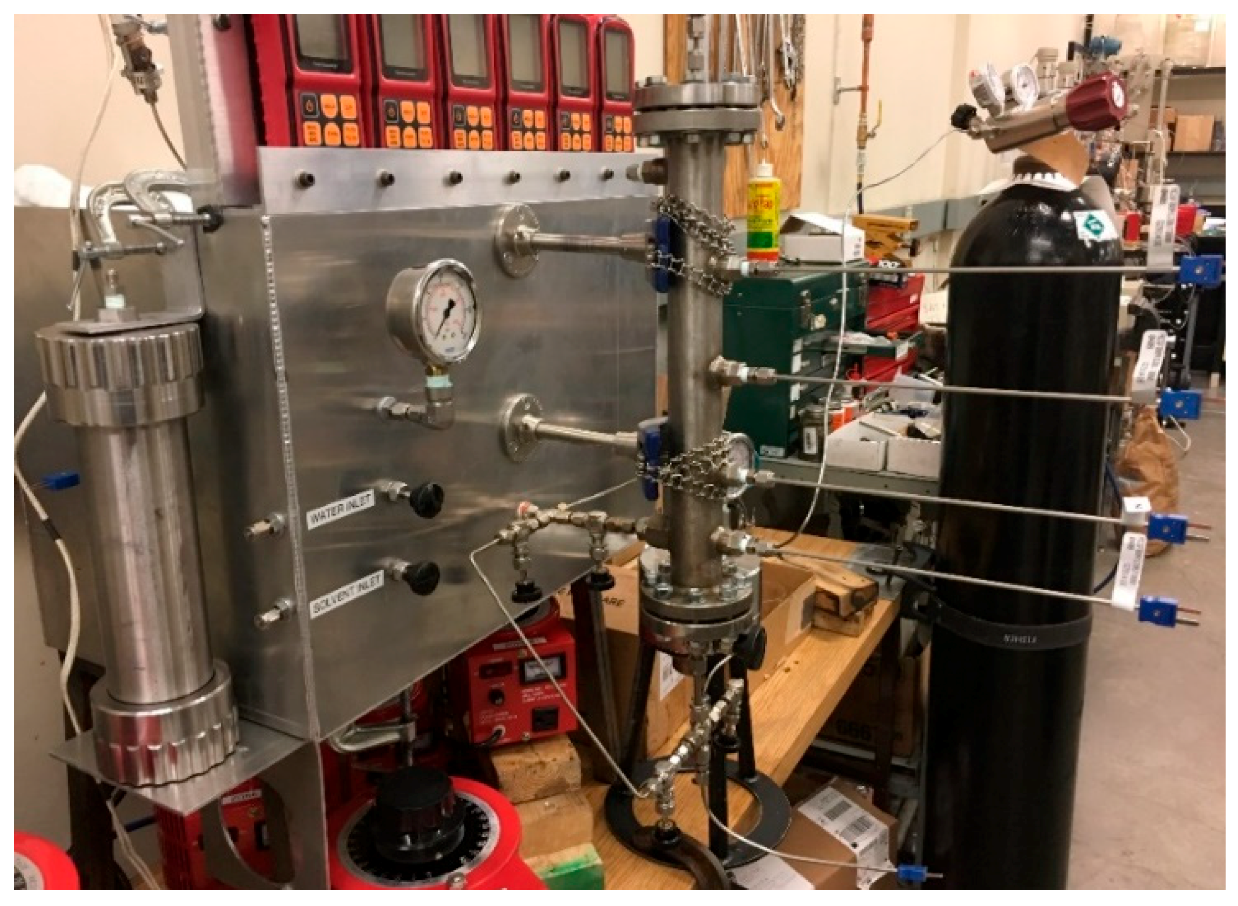
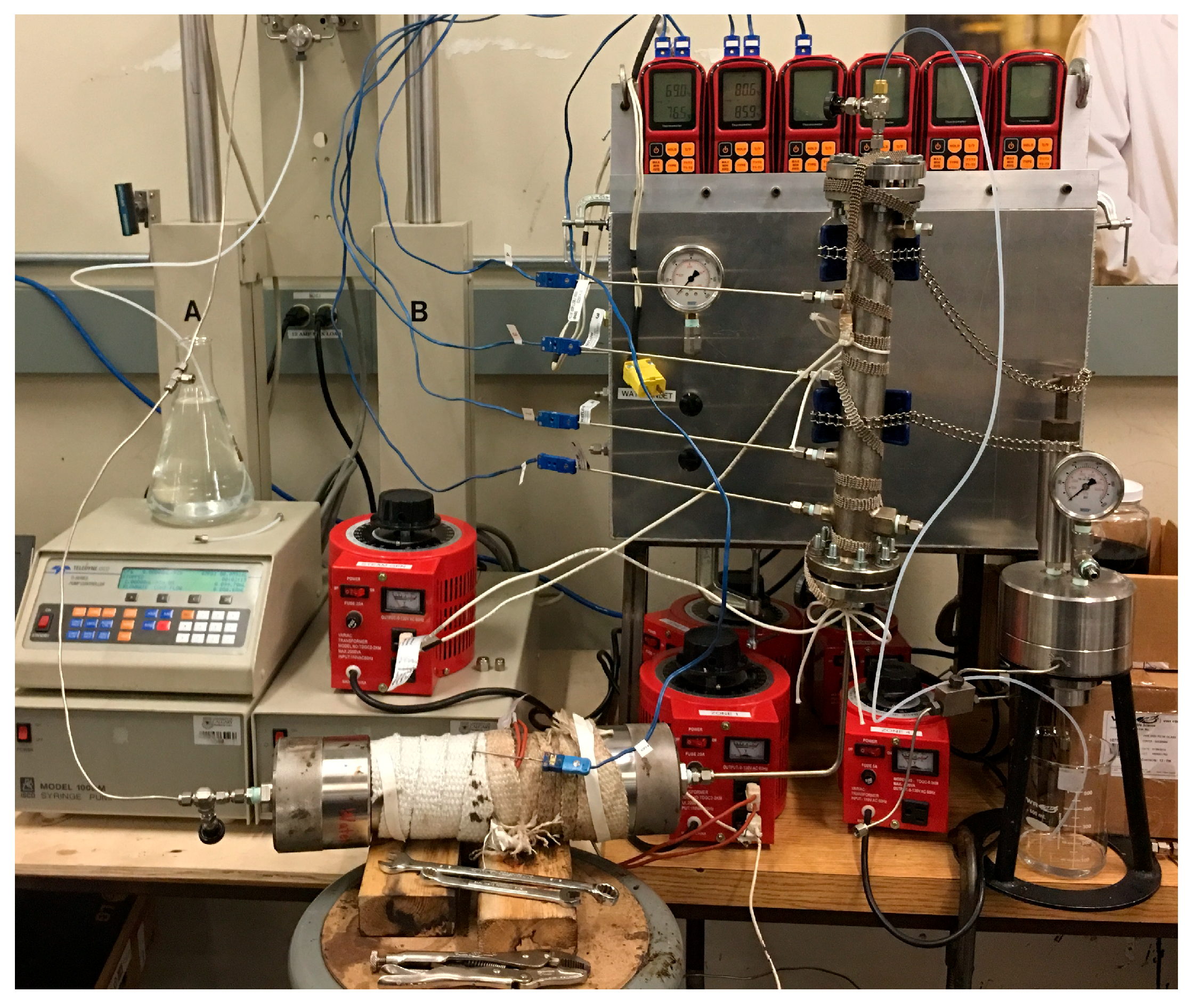
The required steam for the test was generated by using a flow-through steam generator, which contained a full-length rod heater of 3/16 inch diameter placed along the axis of a three-metre-long stainless-steel tube of 3/8 inch diameter. Injection of deionised water into the annulus between the heater and the tube allowed it to pass through the annulus in contact with the electrical heater, thus generating the required steam. This heater and tube assembly was coiled into a six-inch diameter coil, and the whole system was installed within an aluminium box, which subsequently was filled with insulating material. A display with six dual-channel thermocouple readouts to monitor the temperature in the four inner and four outer thermocouples installed on the sand pack was placed at the top of the steam generator case. This display was also connected to the steam generator, steam inlet port and production outlet port (
Figure 2).
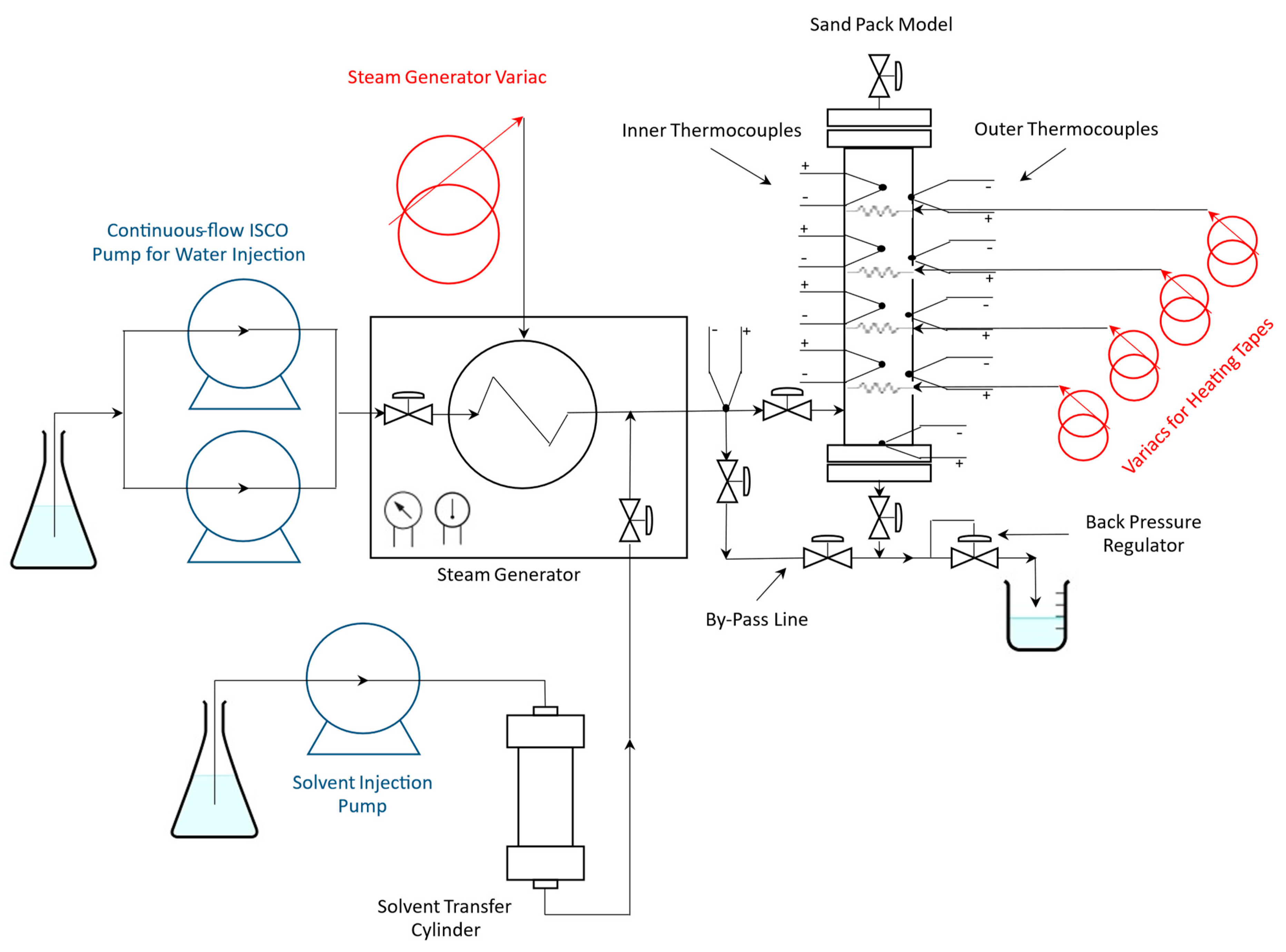
The use of two 300D Syringe pumps and their corresponding Pump Controllers (Teledyne ISCO, Inc., Lincoln, NE, USA) with deionised water for steam generation and one additional for actuation of the solvent transfer cylinder (in the case of ES-SAGD experiments) maintained constant flow rates. For ES-SAGD tests, the outlet line from the transfer cylinder was connected to the line connected from the steam generator to the sand pack inlet to mix the two fluids just before entering the sand pack.
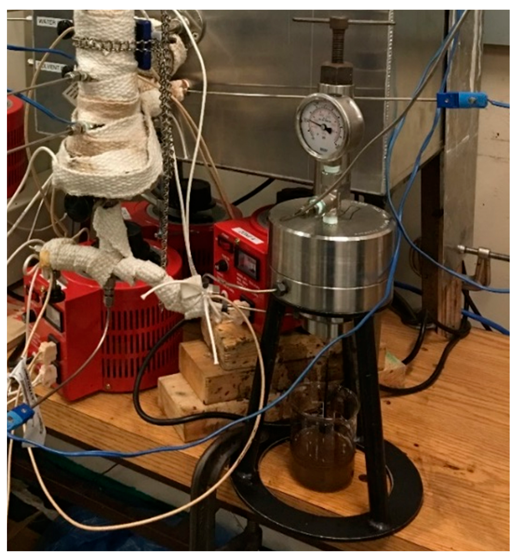
Produced fluids passed through a Back Pressure Regulator (BPR) to keep a constant pressure at the production end of the sand pack. The BPR was set at 230 psi (1.585 MPa) in all tests, and the production line was heated to avoid plugging with the produced bitumen (
Figure 3).
The system configuration is shown in a diagram (
Figure 4), and a picture of the assembled test rig is presented (
Figure 5).
3.3. Sand Packing into the Holder
The sand packing process was initiated with the installation of the bottom endcap and the four internal thermocouples before filling up the holder with Ottawa sand from the top. The sand pack was tapped with a brass hammer during filling to evenly settle the sand. Subsequently, the top endcap was installed, and the bolts were gradually and sequentially tightened to exert axial stress on the sand pack whilst tapping was continued with the hammer. For air removal, CO2 was passed through the sand before evacuating the sand pack with a vacuum pump. It was then saturated with deionised water at 200 psi pressure to dissolve any remaining CO2. Deionised water was passed through the sand pack at 200 psi back pressure to remove any dissolved CO2.
3.4. Permeability and Porosity Measurements
For permeability measurement, a fixed gravity head was applied to flow water through the sand pack and the stabilised flow rate was measured to calculate permeability applying Darcy’s Law as:
where
q is the flow rate (mL/s);
A is the cross-sectional area of the sand pack (cm
2);
μ is the viscosity of the water (cp); Δp is the pressure drop along the sand pack (atm);
L is the length of the sand pack (cm), and
k is the permeability of the sand pack, (darcies).
Finally, the sand pack was flooded with preheated Long Lake bitumen to remove movable water and establish the initial oil saturation.
The bulk volume was calculated after fittings and thermocouple installation by measuring the weight of water needed to fill up the holder with deionised water. The sand pack bulk volume was 155 mL. The weight of sand used in filling it was measured for each test. The weights of the dry sand pack and water-saturated sand pack were also measured to calculate the weight of the water volume being taken as pore volume. Sand pack porosity was then calculated as the ratio between water volume and bulk volume.
3.5. Oil Flooding
All experiments conducted in this study utilised dead oil. The bitumen used was sourced from Nexen and was originally produced through the SAGD process at their Long Lake operation (
Table 1). This oil, collected from the inlet separator, contained a substantial amount of diluent, which was subsequently removed through vacuum distillation using rotary evaporators. A large batch of processed oil was prepared for the experiments, with its viscosity adjusted to match that of the original Long Lake oil by blending it with a portion of the separated diluent. The prepared oil was stored in a freezer until required for testing.
For initial oil saturation determination, warmed bitumen (70 °C) was flooded into the sand pack model by using a 300D Syringe pump and a Pump Controller (Teledyne ISCO, Inc.) whilst a heating tape was used on the sand pack model to make its viscosity manageable (
Figure 6). Given that the oil employed possessed a higher density than water, the flooding process was conducted in a vertically upward direction to enhance sweep efficiency. The produced water during oil flooding was weighed, and its volume was considered the same as the oil volume in the sand pack. The volume ratio between oil and pore volume gives the oil saturation. Correspondingly, the volume ratio between the remaining water and pore volume was considered irreducible water saturation.
After these measurements, the sand pack was wrapped with a first layer of insulation and outer thermocouples were installed on the surface. Heat tapes were wrapped around the first insulation layer and on top of the thermocouples in each zone. As the only source of heat for the sand pack had to be the injected steam, the heat tapes were operated to maintain the temperature on the outside of the inner insulation higher than the room temperature but considerably lower than the temperature in the sand. This reduced the heat loss from the walls of the sand pack.
4. Procedure for Testing and Sample Analysis
For fair comparisons between all tests, it was necessary to maintain the same conditions and experimental protocols throughout the study, including sand mesh size and packing procedure, sand-pack dimensions, preheating period, temperature, steam flow rate, sampling procedures, and post-experiment analyses. To accomplish this goal, three preliminary tests were run to define those parameters delivering a sand mesh (16–30) as the more manageable in terms of run time (around 9.5 h) to collect 20 fluid samples (each injected pore volume) at an injection rate of 2 mL/min whilst allowing the steam chamber to grow up consistently and provide a continuous production rate. Then, three SAGD experiments were performed to validate the functionality of the experimental setup and establish a baseline SAGD for comparison with the ensuing ES-SAGD experiments.
4.1. Steam Injection in Sand Pack
A heating tape was used to preheat zone 1 of the sand pack to 70 °C by reading the temperature of its inner thermocouple. To ensure superheated steam injection into the sand pack, the bypass valves were opened whilst keeping the inlet and production outlet valves on the sand pack closed until the fluid from the steam generator flowed at 207 °C under 230 psi (1.585 MPa) pressure. Once the steam temperature stabilised at superheated conditions, the bypass valves were closed, and the flow into the sand pack started. The flow rate was maintained at 2 mL/min throughout the test by switching between two syringe pumps, and temperature and pressure were recorded at 15–20 min time steps until 20 hydrocarbon pore volumes (HCPV) of steam were injected.
4.2. Sand Pack Depressurisation
The termination of the SAGD and ES-SAGD experiments was carried out using a carefully controlled procedure where the electrical power to both the preheater and steam generator was switched off, whilst water flow was maintained to facilitate their gradual cooling. The water flow rate was progressively reduced and completely stopped once the preheater and steam generator reached a safe temperature of approximately 100 °C or lower.
Finally, the water pump was shut down, and the depressurised sand-pack model was disconnected from the injection and production lines.
4.3. Produced Fluid Analysis
Liquid samples collected during the test were utilised to calculate the volume of oil produced. The methodology used for such fluid sample analysis was different for solvent-free SAGD tests and the ES-SAGD tests, as described below.
4.3.1. SAGD Experiments
30 mL of toluene was added to each sample to break the bitumen-water emulsion. The samples were then transferred to separatory funnels. After allowing sufficient time to settle each phase apart, the water layer (located at the bottom) was removed. The supernatant hydrocarbon phase was separated, and its density was measured using a pycnometer.
The measured density was used to determine the volume of bitumen in the original produced sample. The toluene-bitumen density mixture density is related to the fraction of bitumen in the mixture by the relationship described below:
where
ρm is the density of the bitumen-toluene mixture (g/mL);
vt is the volume fraction of toluene (%);
ρt is the density of toluene (g/mL);
vb is the volume fraction of bitumen (%), which is equal t
o (1 − v
t); and
ρb is the density of bitumen (g/mL). This equation gives the volume fractions of bitumen and toluene in the supernatant fluid, and knowing that the total volume of toluene added was 30 mL, the volume of bitumen can be determined. The equation above assumes an ideal solution. This was confirmed by preparing several mixtures of toluene and bitumen and measuring their density. The prepared mixture showed no significant deviation from the linear relationship to concentration.
4.3.2. ES-SAGD Experiments
During the coinjection tests, the fluid (containing water, bitumen and solvent) was produced at a high temperature (at the boiling point of water) after the BPR, and due to the highly volatile nature of the solvent, most of the solvent evaporated from the open sample vessels during the sample collection. To facilitate near-complete removal of the solvent, the open collection vessels were left open for 24 h. The samples remaining in the vessel contained mostly bitumen and water. These samples were analysed using the Dean-Stark distillation technique to separate the water. The mixture of bitumen and toluene remaining in the distillation flask was analysed for its bitumen content using the density method described above.
4.4. Sand Analysis
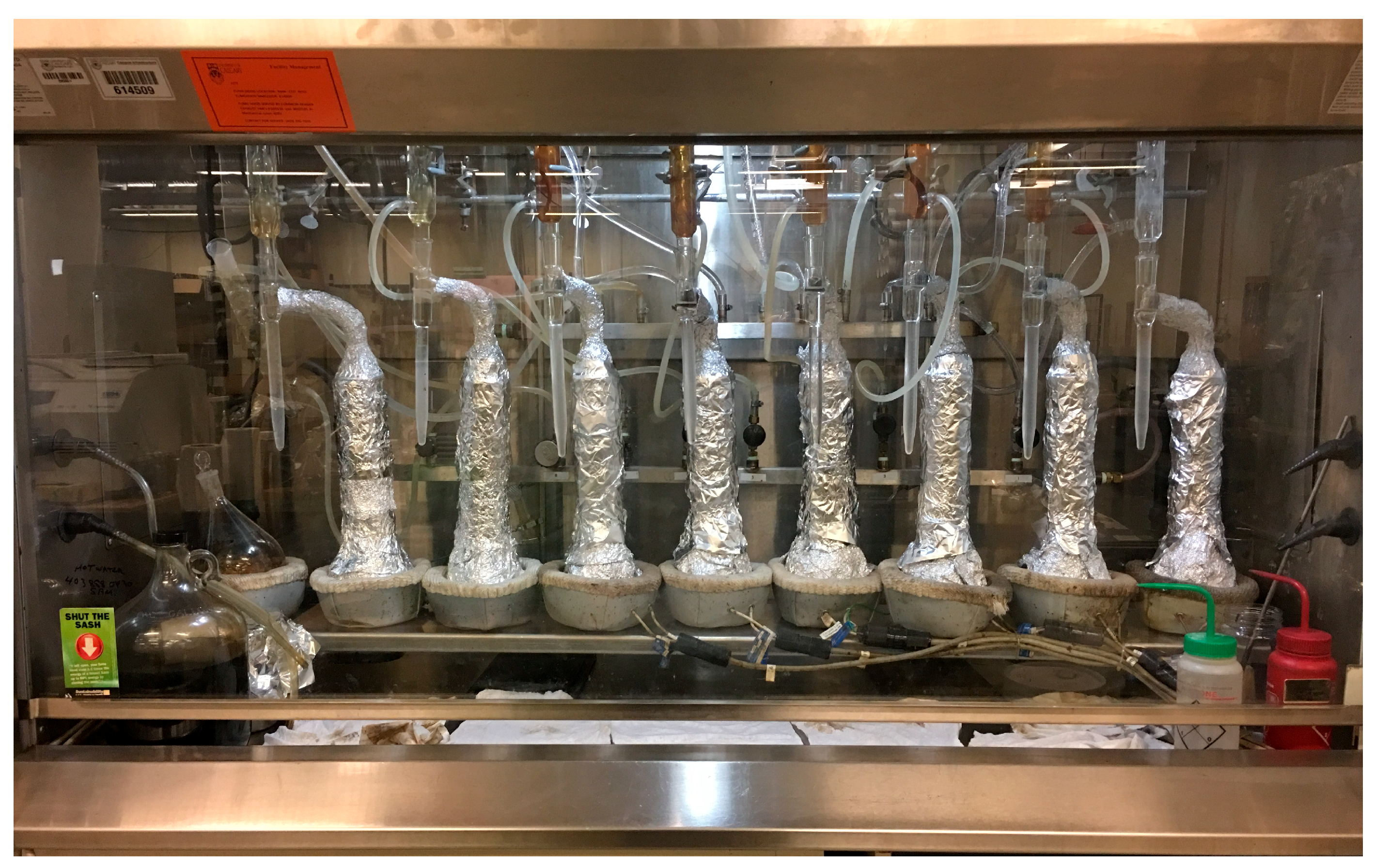
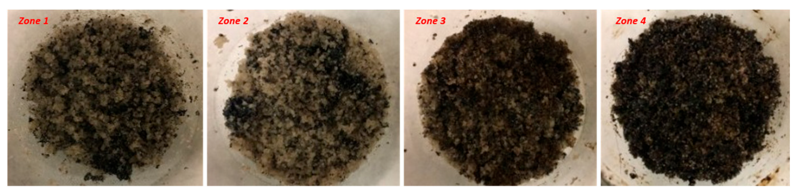
After sand-pack depressurisation, the sand matrix was removed and inspected in each of the four zones. The whole matrix was weighed and analysed using the Soxhlet extraction method (
Figure 7) to determine water and residual oil content.
The sand matrix was loaded into an extraction thimble and put inside the main chamber of the Soxhlet extractor. Toluene vapour flowed up into the Soxhlet chamber housing the thimble and further up into the condenser, after which it cooled and dripped down into the Soxhlet chamber. Co-distilled water and condensed toluene were continuously separated in a trap to recycle toluene through the extraction thimble, thereby dissolving the bitumen in the sand matrix, whilst retaining the co-distilled water in the trap.
The warm toluene dissolved the bitumen in the thimble and dripped into the distillation flask. This process was carried out until toluene without any more bitumen dripped into the distillation flask. A material balance approach was used to calculate the amounts of water, bitumen and sand separated physically. Oil weight was calculated from recorded weights of the original sand matrix, cleaned-dry sand and water collected in this process.
5. Results and Discussion
5.1. Base-Case SAGD
After the preliminary tests to confirm satisfactory performance of the rig were completed and the test parameters were defined, a Base-Case SAGD test was conducted. The properties of the sand pack prepared for this test are listed (
Table 2).
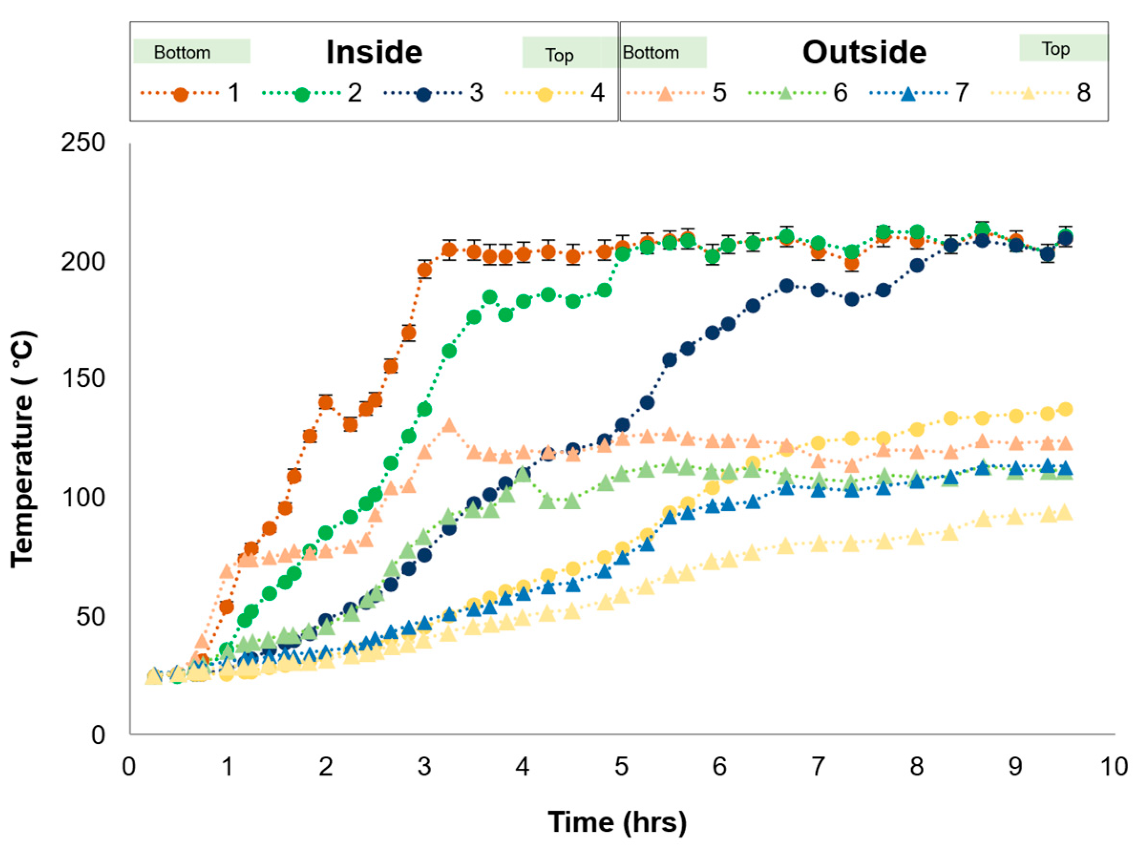
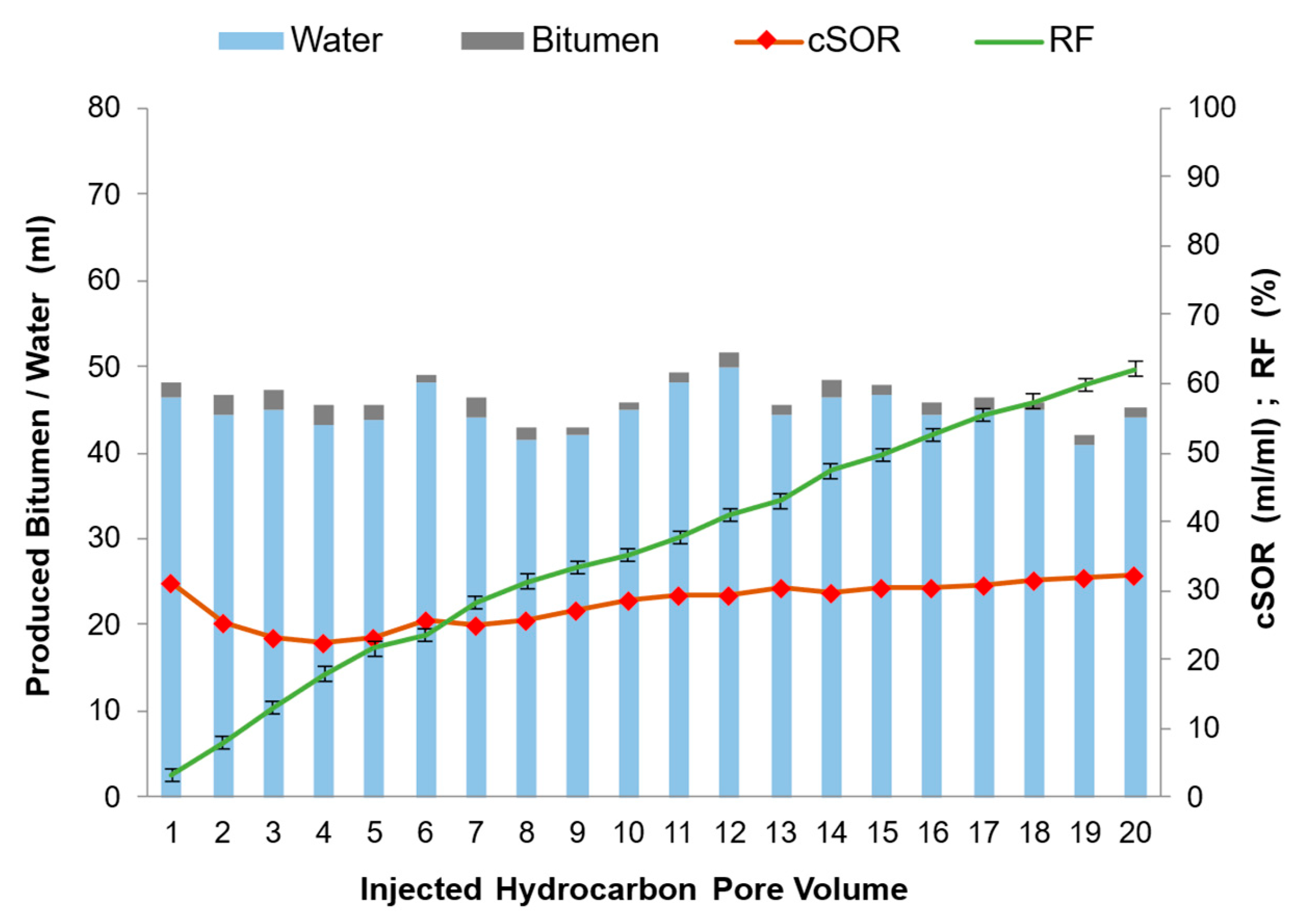
The temperature rise in the four zones recorded during this test is shown (
Figure 8). The temperature in zone four did not rise to the steam temperature (207 °C), showing that the heat loss from the walls of the sand pack prevented the steam front from reaching the top of the sand pack. This may have restricted the whole bitumen drainage from this zone and possibly reduced the final RF (
Figure 9). However, the steam chamber propagation in the first three zones was noticeable in the analysed samples and recorded temperature profiles.
After completing the steam-assisted gravity drainage test and collecting the produced fluid in discrete samples, the sample analysis was performed according to the protocols described earlier. Residual oil saturation (S
or) was measured directly on the extracted sand samples from the sand pack and also calculated through material balance (
Table 3).
The analysis of the collected samples allowed the plotting of RF (recovered bitumen divided by HCPV) versus the volume of steam injected for performance evaluation of the process (
Figure 10).
5.2. ES-SAGD—Pentane Coinjection
With reliable data from Base-Case—SAGD to compare with, the tests for single-component solvent coinjection were conducted using pentane at several volume fractions in the injected fluid, using sand packs whose properties are listed below (
Table 4).
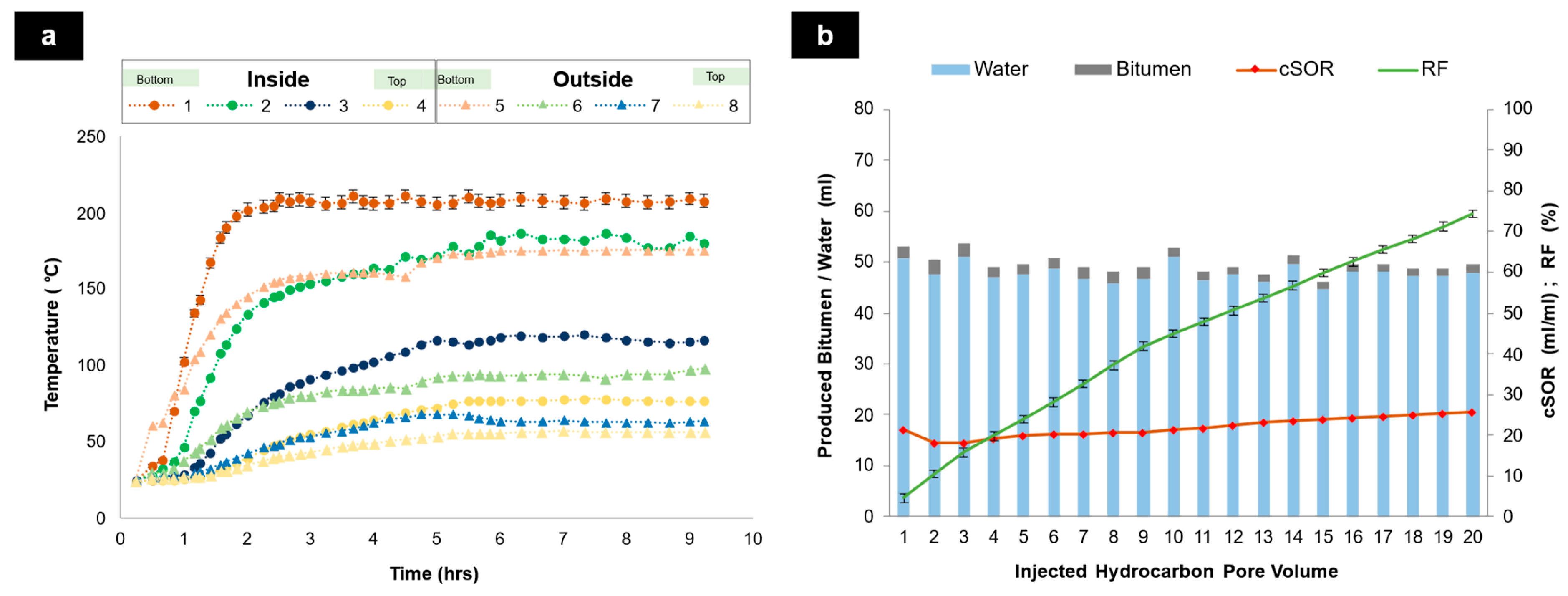
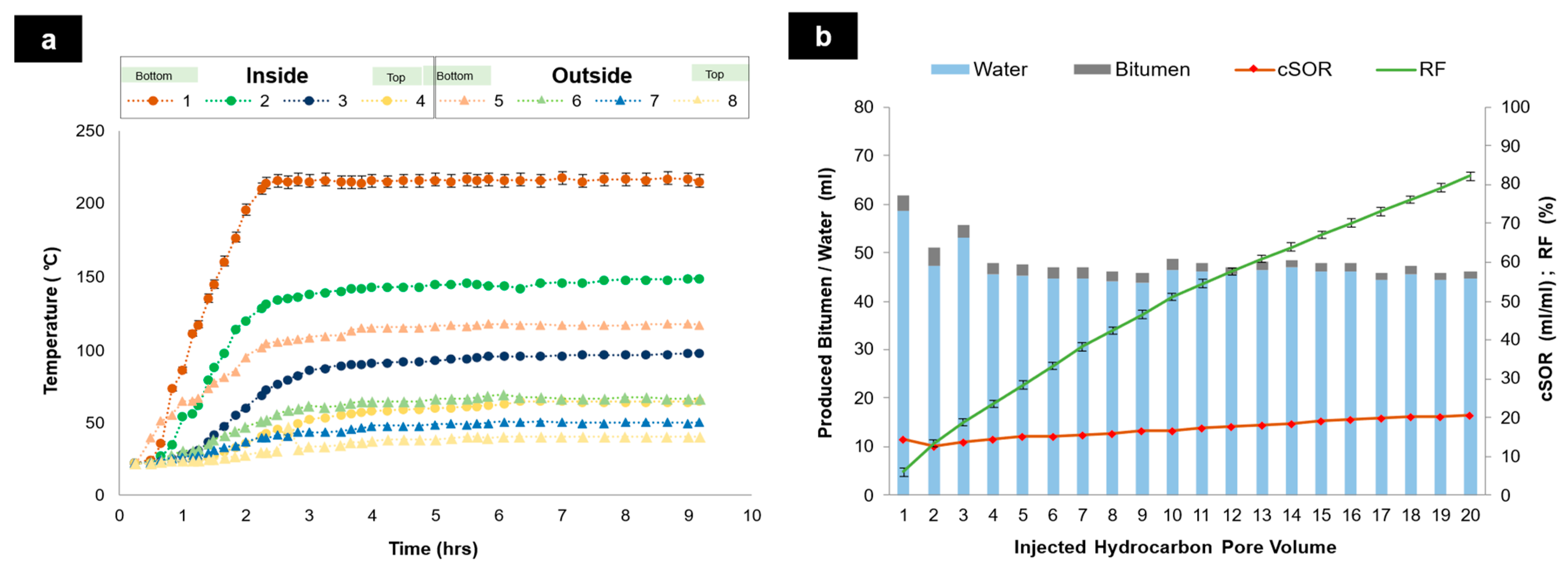
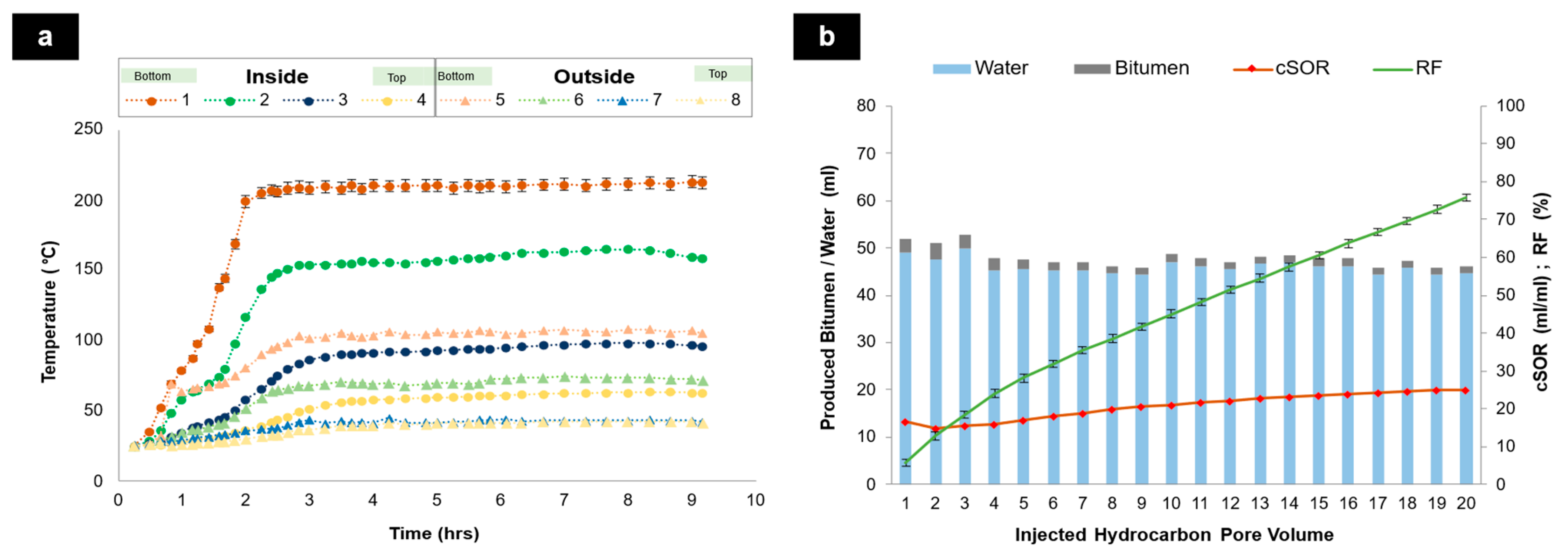
In the test using pentane at 5 vol%, the final temperatures in sand-pack zones two, three and four were not as high as in the Base-Case. Moreover, those final stabilised temperatures were achieved faster than the Base-Case (
Figure 11a). In the cases of pentane at 10 vol% and 15 vol% coinjection, the final temperatures in these zones were even lower (
Figure 12a and
Figure 13a). The performance of pentane in these three figures suggested lower energy requirements compared to the Base-Case SAGD, as expected, and this effect was accentuated gradually with increasing concentration of pentane. The presence of solvent vapour reduces the partial pressure of steam, resulting in a lower saturation temperature.
For these tests of pentane coinjection, the volumes of collected samples were quite similar in volume, whilst the RF increased with rising concentration of pentane, as shown (
Figure 11b,
Figure 12b and
Figure 13b). The cSOR in these three tests decreased sequentially as the solvent concentration increased.
As per the protocol for sample analysis, Sor was determined from (1) the extraction of the sand matrix and (2) by material balance, evidencing a small difference between the two results for each experiment (
Table 5). The S
or determined from the sand extraction is more accurate, as it is a direct measurement, whereas the material balance value is based on the difference between two larger saturations. The residual oil saturation decreased with increasing pentane concentration.
5.3. ES-SAGD—Hexane Coinjection
The next three tests involved the coinjection of hexane. Again, the concentration coinjected was varied at 5, 10 and 15 vol% for each test, respectively. The characteristics of the three sand packs used in these tests are listed (
Table 6).
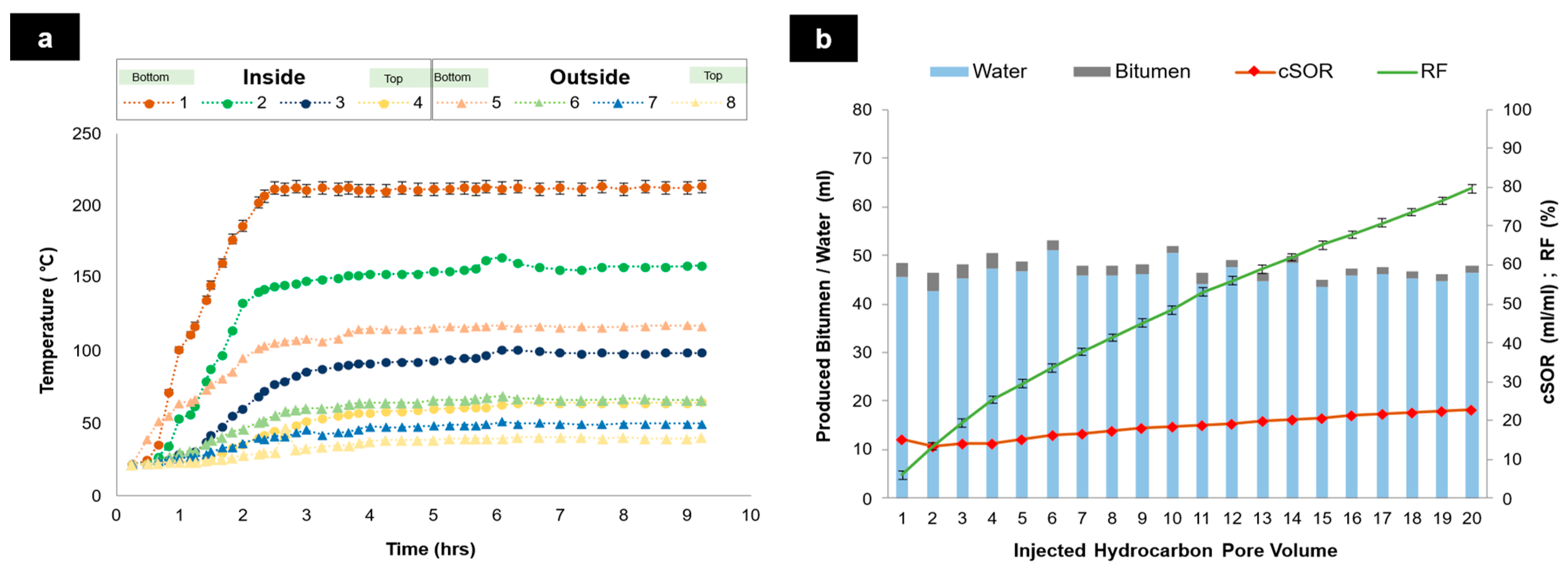
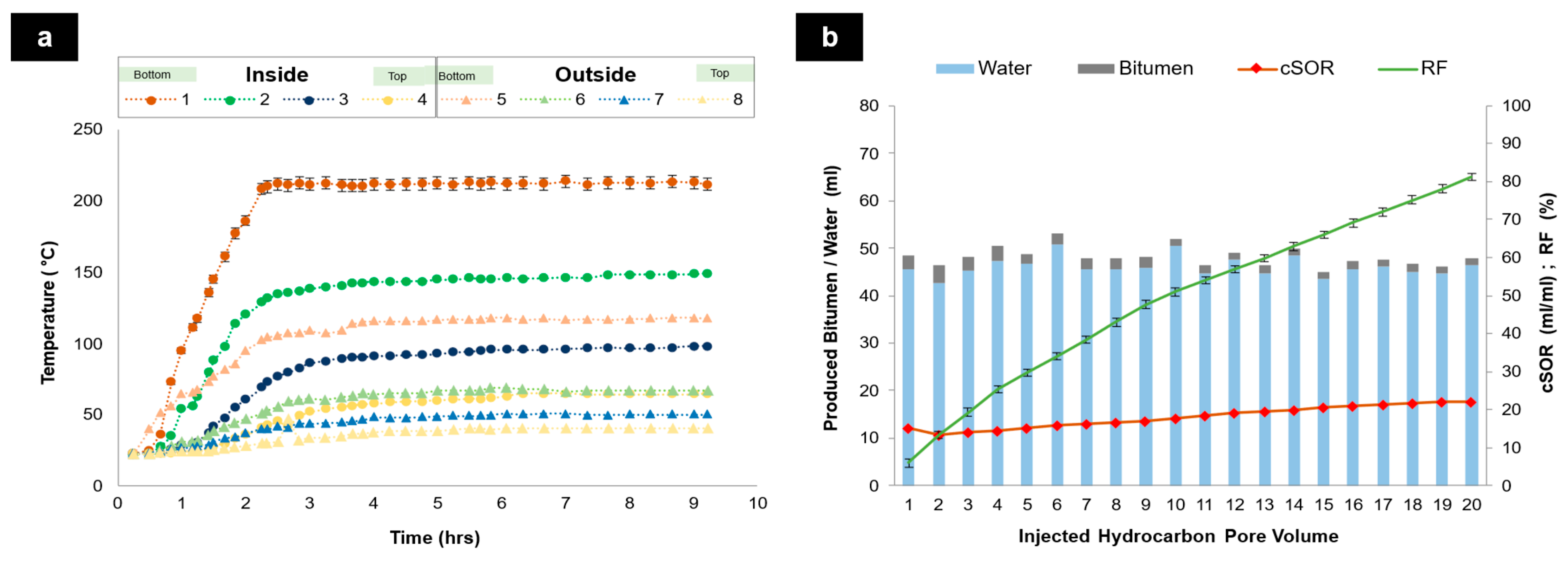
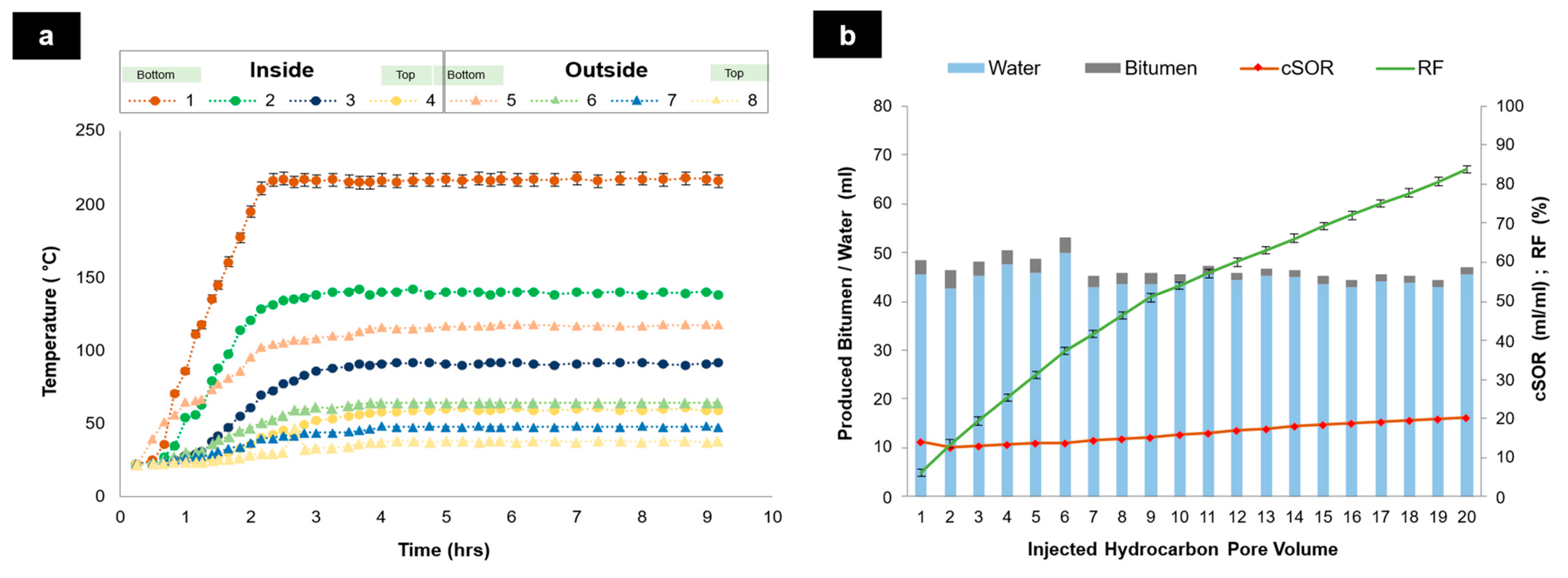
The liquid solvent was mixed with the steam near the inlet of the sand pack and was vaporised by the steam. Final temperatures in sand-pack zones two, three and four were again lower than those for the Base-Case—SAGD and even somewhat lower compared with pentane experiments (
Figure 14a,
Figure 15a and
Figure 16a).
When hexane was coinjected, the produced samples contained higher bitumen volume compared to Base-Case-SAGD and also compared with pentane coinjection (
Figure 14b,
Figure 15b and
Figure 16b), and the cSOR decreased as the solvent volume fraction increased.
The cumulative injection volume was in the range of 1000–1006 mL. The residual oil saturations based on sand extraction and material balance are listed (
Table 7). The residual oil saturations were lower with hexane compared to pentane at all three concentrations, showing that hexane is a better solvent than pentane for ES-SAGD.
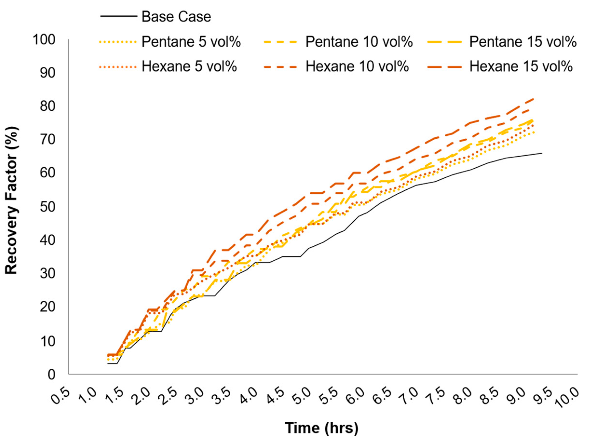
The recovery performance of the six ES-SAGD tests is compared against the Base-Case SAGD (
Figure 17). The RF improved with increasing solvent concentration, but the incremental improvement for each increase in the solvent concentration became smaller at higher concentrations.
It is noticeable that a significant improvement in RF performance occurred with pentane coinjection at all three concentrations. For the cases of 10% and 15% pentane, the final RF difference is not that large, suggesting that the optimum concentration for this solvent may be around 10 vol%. It was noted that the higher concentration of 15 vol% allowed a boost to the recovery behaviour in the early stage of the test, whilst losing its effectiveness onwards. This suggests that it may be advantageous to start at a higher solvent concentration and then gradually reduce the solvent amount in the later stages of production.
During the test with a hexane concentration of 5 vol%, RF increased by 13.7%, surpassing the 5 vol% pentane coinjection performance (12.2%). There was a significant improvement when reaching 10 vol% and only a small further gain at 15 vol%. Moreover, with hexane, the enhancement was more pronounced for higher concentrations in the later stage of the test.
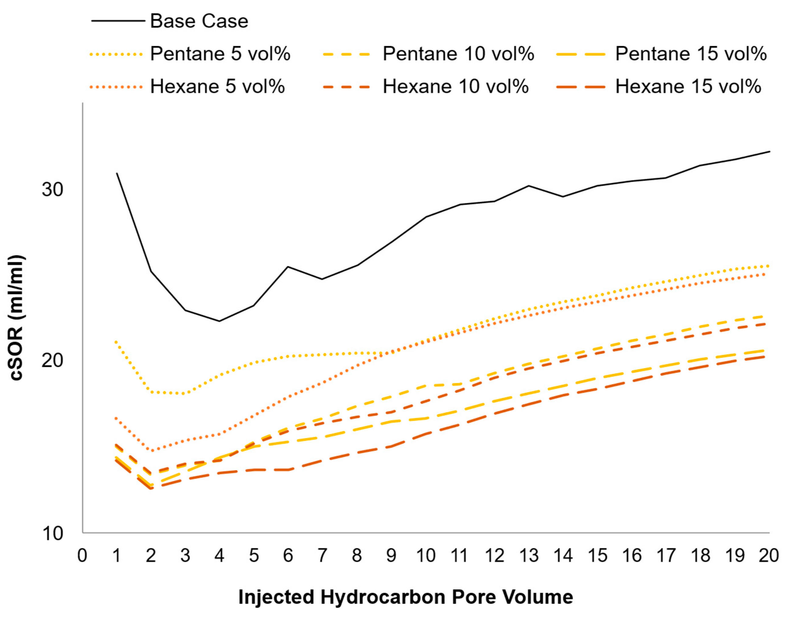
At the same time, the six ES-SAGD tests show an improved cSOR compared to the Base-Case SAGD (
Figure 18). The cSOR diminished with increasing solvent concentration, but the incremental improvement for each increase in the solvent concentration became smaller at higher concentrations. During the test with a hexane concentration of 5 vol%, cSOR decreased by 23% at a very early stage of the injection, outperforming the 5 vol% pentane coinjection. When reaching 10 vol%, both solvents presented quite similar performance, with only some differences during the mid-test. Nonetheless, at 15 vol% hexane, cSOR for hexane was better than that of pentane during the early stage and towards mid-test, and this performance lasted longer.
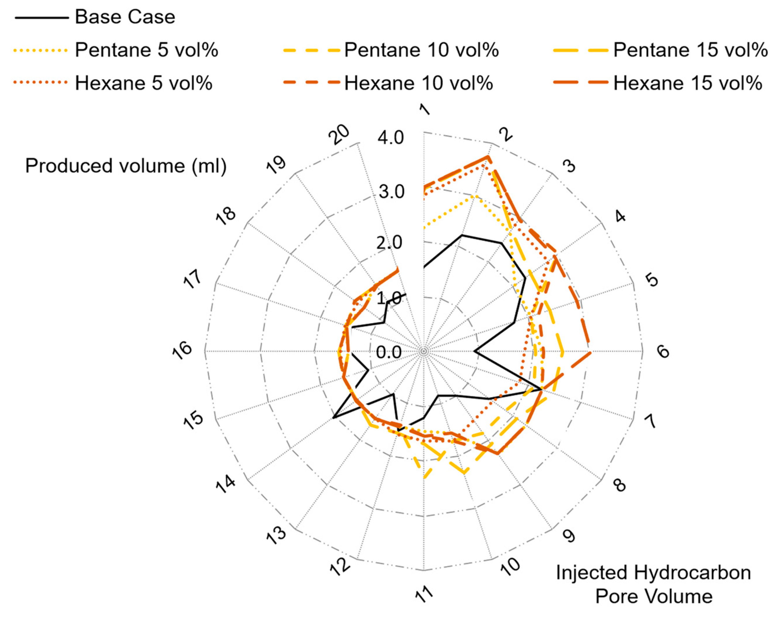
Early-stage solvent coinjection facilitates the establishment of hydraulic communication between the SAGD injection and production wells, thus accelerating the production ramp-up phase (
Figure 19). The experimental results indicate that the oil rate drainage from pentane coinjection showed a higher oil rate drainage during the very early stage of the tests. Its performance decreased, but the effect remained until mid-test and finally stabilised at the end of the tests. Nonetheless, hexane injection is generally higher in the early stage of the ES-SAGD process. Its mobilisation effect sharply declines and remains low for the rest of the tests, making it less effective in the later stages of the process.
An improved solvent efficiency can be achieved by adjusting operating parameters such as the start time for the solvent coinjection, the duration of the steam-solvent coinjection period and the solvent concentration in the steam-solvent mixture.
The interplay between pressure, temperature, and solvent concentration must be carefully managed to ensure that the injected solvent remains in the vapour phase within the steam chamber, optimising its effectiveness. Increasing the concentration of the coinjected solvent can further improve ES-SAGD performance; however, the incremental gains become less pronounced at higher concentrations.
5.4. Uncertainty Analysis
An overall measurement uncertainty of approximately 3.5% was estimated for the volumetric data, as exemplified by the recovery factor’s curves. This uncertainty stems from different contributing factors detailed below.
To sustain the target injection rate of 2 mL/min, the system alternated between two pumps for steam injection, each with a maximum capacity of 300 mL. This intermittent switching introduced transient flow fluctuations within the sand pack, which in turn affected the constant production rate and could induce flow batching. The recovery factor was calculated using samples collected from each pore volume injected, and the volume readings carried an inherent instrument error of ±0.1 mL for the set flow rate.
For temperature measurement, the thermocouples used have an uncertainty of ±2.0 °C within the operational range, and the readouts are displayed with a resolution of ±0.1 °C. This estimated variation is reflected in the readings for the zone 1 curves.
Measurements involving volumes and masses were subject to inherent uncertainties due to instrument limitations (volumetric ±0.1 mL, weighing ±0.01 g) and user technique. The total uncertainty considers both systematic errors and random errors, accounting for 3.0%.
Readings of temperature and pressure were recorded manually during a ~5-min period. Therefore, the continuity in measurements is estimated during plotting.
6. Conclusions
The results underscore the substantial advantages of incorporating solvent into the injected steam. The incorporation of hexane as a steam additive demonstrated superior production performance in SA-SAGD experiments compared to pentane-assisted SAGD. For both solvents, higher concentrations in the injection stream enhanced pore-scale sweep efficiency and increased ultimate RF values. For equivalent solvent volume fractions, mixtures containing pentane exhibited a marginally higher cumulative oil production compared to those with hexane. Nonetheless, the in situ viscosity reduction in heavy oil within the cell was more pronounced in the presence of hexane, indicating a stronger dilution and mobilisation effect relative to pentane mixtures.
Key benefits include a reduction in operating temperature, which in turn minimises heat losses and enhances overall thermal efficiency. The lowered thermal requirement also permits a decrease in steam consumption, thereby reducing the emission of flue gases associated with steam generation. Moreover, the presence of solvent facilitates accelerated mobilisation and recovery of oil from the reservoir, contributing to improved production performance. Although only temperature and pressure among the various real operational parameters were tested, solvent selection emerges as the most pivotal factor governing the success of ES-SAGD processes. The choice of solvent is predominantly influenced by two essential criteria: the vapour pressure of the solvent under reservoir operating conditions and its chemical affinity or interaction with bitumen; therefore, any adverse impact is avoided.
Optimising solvent and steam recovery to enhance the thermal efficiency of the process hinges on determining the optimal injection volumes and pressures based on both steam and solvent. To advance understanding and enhance practical applicability, future experimental investigations should include multicomponent-solvent coinjection, particularly employing cracked naphtha and natural gas condensate. Such efforts are essential for informing the development of optimised solvent coinjection design and potential operational strategies aimed at optimising the SOR of the ES-SAGD process, mitigating pore medium plugging and ensuring a sustained production performance and higher RF with lower water and energy consumption. This optimisation aims to effectively leverage the interplay between solvent concentration and temperature to maximise bitumen mobility in the steam chamber.


