Abstract
This study numerically examines laminar natural convection within a square cavity that has a horizontally attached adiabatic fin on its heated vertical wall. The analysis employed the finite element method to investigate how fin position, length, thickness, and thermal conductivity affect heat transfer behavior over a broad spectrum of Rayleigh numbers (Ra = 10 to 106) and Prandtl numbers (Pr = 0.1 to 10). The findings indicate that the geometric configuration and the properties of the fluid largely influence the thermal disturbances caused by the fin. At lower Ra values, conduction is the primary mechanism, resulting in minimal impact from the fin. However, as Ra rises, convection becomes increasingly significant, with the fin positioned at mid-height (Yfin = 0.5), significantly improving thermal mixing and flow symmetry, especially for high-Pr fluids. Extending the fin complicates vortex dynamics, whereas thickening the fin improves conductive heat transfer, thereby enhancing convection to the fluid. A new fluid-focused metric, the normalized Nusselt ratio (NNR), is introduced to evaluate the true thermal contribution of fin geometry beyond area-based scaling. It exhibits a non-monotonic response to geometric changes, with peak enhancement observed at high Ra and Pr. The findings provide practical guidance for designing passive thermal management systems in sealed enclosures, such as electronics housings, battery modules, and solar thermal collectors, where active cooling is infeasible. This study offers a scalable reference for optimizing natural convection performance in laminar regimes by characterizing the interplay between buoyancy, fluid properties, and fin geometry.
1. Introduction
Natural convection in differentially heated cavities is crucial for understanding many heat transfer applications, including electronic cooling, solar thermal collectors, and industrial thermal management systems [1,2,3]. By investigating how fluid motion arises purely from temperature gradients and buoyancy effects, researchers gain fundamental insights into thermo-fluid behavior in confined spaces. Heat dissipation efficiency in these applications relies heavily on how well fluid flow and temperature distribution are regulated within the enclosure. The attachment of fins to the hot wall of a cavity is a common technique to enhance heat transfer by increasing the surface area and modifying fluid flow patterns, thereby improving thermal efficiency [4,5]. These modifications impact velocity profiles, affect the development of the thermal boundary layer, and significantly alter the overall heat transfer coefficient [6,7]. The effectiveness of these improvements hinges on several key factors, including the Rayleigh number (Ra), which assesses the strength of buoyancy-driven flow; the Prandtl number (Pr), which characterizes thermo-fluid properties; and the geometric configuration of the cavity, which affects natural convection patterns and thermal gradients within the enclosure [8]. Furthermore, the effectiveness of finned surfaces can vary significantly based on factors such as fin geometry, spacing, material properties, and computational fluid dynamics techniques, making it essential to optimize these parameters for specific applications [9].
The orientation of the fin, whether horizontal, vertical, or inclined, has a pronounced impact on the thermal and flow characteristics within differentially heated enclosures. Nag et al. [10] examined horizontal fins and demonstrated that their arrangement and conductivity significantly affect heat transfer performance. Bilgen [11] extended this investigation by comparing vertical and horizontal orientations, concluding that short vertical fins placed near insulated boundaries tend to optimize convective transport. More recently, Khetib et al. [12] introduced inclined fins, where they found that tilting them toward the top or bottom wall can further enhance heat transfer by promoting plume detachment and increasing circulation intensity.
Fin length significantly influences heat transfer in natural convection, particularly at low Rayleigh numbers, where longer fins enhance thermal performance by increasing surface area, as demonstrated by Dou and Jiang [13]. However, at high Ra, this benefit diminishes as extended fins obstruct buoyant flow, introducing a trade-off between surface enhancement and flow interference.
The position of the fin on the hot wall is another critical factor. Placing the fin at the middle height of the cavity often results in the most efficient heat transfer, as demonstrated by Shi and Khodadadi [14]. However, this may vary depending on the fin length and the Rayleigh number.
Varol and Ozgen [15] investigated the effect of fin thickness and found that thicker fins can act as control parameters for heat and fluid flow, especially at higher Rayleigh numbers. The fin’s thickness affects the system’s thermal and hydrodynamic behavior. Thicker fins can increase the heat transfer surface area but may also increase the pressure drop and potentially reduce the flow rate.
The thermal conductivity of the fin material plays a critical role in heat transfer enhancement, as it governs the rate of heat diffusion from the hot wall into the fluid. Jourabian et al. [16] demonstrated that increasing the fin-to-fluid conductivity ratio improves thermal performance substantially in natural convection-dominated cavities.
Computational fluid dynamics (CFD) techniques, such as the finite volume method (FVM) and the lattice Boltzmann method (LBM), have been widely used to simulate natural convection in square cavities with fins. These methods provide detailed insights into the temperature and velocity fields, enabling the optimization of fin design and placement. De Vahl Davis [17] set a well-known benchmark for natural convection in square cavities, illustrating that convective transport is highly responsive to variations in Ra. Markatos and Pericleous [7] built upon this by examining both laminar and turbulent flow regimes, showing that turbulence greatly enhances heat transport. Recently, computational advancements like multigrid finite volume methods have enhanced the accuracy of high-Ra simulations, leading to improved predictions of convective heat transfer characteristics [8]. Chen et al. [18] combined computational fluid dynamics (CFD) with experimental validation, validating that fin-induced convection significantly impacts temperature and velocity distributions in confined spaces. Vesper et al. [19] showed that thermally conductive walls hasten turbulence transition, resulting in changes to convective instabilities and heat flux distribution.
While several studies have investigated the influence of fin geometry, position, thickness, and material properties on natural convection in square cavities, many of these works, including those by Elatar et al. [9], focused on limited ranges of Prandtl numbers and did not systematically decouple the effects of individual fin parameters. Most existing analyses also consider air or a single working fluid, neglecting the broader implications of varying Prandtl numbers, which span orders of magnitude in practical applications, from low-Pr liquids like molten metals to high-Pr oils. As a result, the generalizability of these findings across different fluids remains unclear. Moreover, previous research has largely emphasized global heat transfer metrics, such as the average Nusselt number, without conducting detailed regional analyses of flow behavior or vortex structure evolution, which are essential for understanding the localized thermal performance within the cavity.
To address these limitations, the present study provides a comprehensive parametric investigation over a wide range of Rayleigh numbers (10 ≤ Ra ≤ 106) and Prandtl numbers (0.1 ≤ Pr ≤ 10), systematically isolating the effects of fin length, thickness, vertical position, and thermal conductivity ratio. This presents a technical challenge due to the nonlinear and coupled nature of buoyancy-driven flows, especially when geometric and material effects interact across regimes ranging from diffusion-dominated to convection-dominated behavior. Unlike prior works that either limited the scope to fixed fin geometries or focused solely on global averages, this analysis decouples the geometric and material contributions of the fin and examines their interplay with buoyancy-driven flow.
The present study advances the understanding of how fin geometry interacts with buoyancy-driven flow across both conduction- and convection-dominated regimes. It clarifies the role of fin placement, length, thickness, and conductivity in shaping vortex structures, thermal stratification, and localized heat transfer within laminar enclosures. These insights are particularly valuable for improving the design of passive thermal management systems used in electronics cooling, battery packs, and solar thermal collectors, especially in applications where forced convection is impractical. By examining spatial variations in heat transfer and flow behavior through wall-resolved temperature gradients and streamline patterns, the analysis provides practical guidance for enhancing performance through purely passive means. These findings are particularly relevant to passive cooling applications where reliability, noise reduction, or energy efficiency prohibit the use of fans or pumps. Design guidelines derived from this work can assist engineers in selecting appropriate fin dimensions and placements to maximize heat removal and dissipation in compact thermal enclosures.
To the authors’ knowledge, this is the first numerical study to comprehensively map fin-induced natural convection behavior across five orders of magnitude in Ra and two orders of magnitude in Pr, while distinctly analyzing the isolated influence of each fin parameter under laminar flow conditions. The selected ranges of geometric, thermal, and fluid properties reflect operating conditions typical of electronics housings, battery modules, and sealed solar receivers. This unified treatment enables more precise identification of design-sensitive configurations and provides a benchmark for optimizing passive heat transfer enhancement strategies in thermally driven enclosures.
2. Problem Definition and Mathematical Model
Figure 1 depicts the schematic representation of natural convection within the enclosure. The analysis examines a square cavity where the length (l) matches the width (w), promoting geometric symmetry. The cavity’s depth is considered much greater than its width, enabling a two-dimensional treatment of the problem with minimal changes in the third dimension. This assumption guarantees that depth variations do not influence the numerical solution.
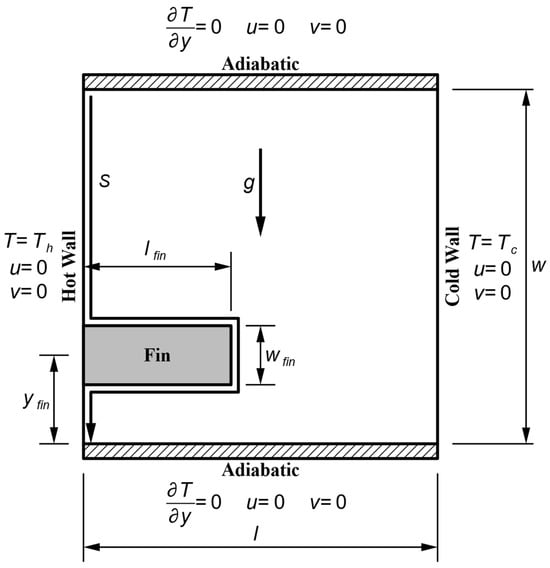
Figure 1.
Schematic representation of natural convection in a square enclosure with a horizontal fin attached to the hot wall, illustrating boundary conditions, cavity dimensions, and fin placement.
The thermal boundary conditions are defined such that the left wall is maintained at a uniform hot temperature (Th) while the right wall is kept at a uniform cold temperature (Tc). This temperature gradient induces buoyancy-driven flow, leading to natural convection within the cavity. The top and bottom walls are adiabatic, ensuring that no heat flux () occurs across these surfaces. A no-slip condition is applied at all solid boundaries, meaning the velocity components are zero (u = 0, v = 0) at these locations.
A horizontal fin with a width (wfin) and length (lfin) is placed inside the cavity along the hot wall at a vertical position to enhance heat transfer performance. The fin acts as a thermal disturbance, modifying the flow structures and altering the heat transfer characteristics within the enclosure. Its presence influences the formation of thermal boundary layers and affects the convective circulation. The study systematically investigates the impact of fin geometry, including its size, position, and thermal conductivity, on the overall heat transfer performance. Figure 1 presents the schematic configuration of the problem, illustrating the boundary conditions, cavity dimensions, and fin vertical position along the hot wall. The present study aims to analyze how the presence of a horizontal fin affects the natural convection process and to determine optimal configurations for enhancing thermal performance in enclosures.
The fin is constructed from a solid material with thermal conductivity (kfin). The cavity is filled with an incompressible, viscous Newtonian fluid characterized by its constant kinematic viscosity (ν) and thermal diffusivity (α). These properties are defined as follows:
where is the fluid density, is the thermal conductivity of the fluid, is the specific heat capacity of the fluid at constant pressure, and is the dynamic viscosity of the fluid.
The governing equations describing the present problem consist of the continuity, momentum, and energy equations. In addition to the previously stated assumptions, heat radiation and viscous dissipation are neglected. The gravitational force acts in the negative y-direction. Since the fluid is assumed to be incompressible and in a steady-state condition, density variations are ignored except in the buoyancy term, which is modeled using the Boussinesq approximation. Under this assumption, the density ρ is treated as a constant everywhere except in the body force term, which varies proportionally with temperature.
The dimensionless forms of x-coordinate (), y-coordinate (), velocity in x-direction (), velocity in y-direction (), pressure (), and temperature () are , , , , , and , respectively. These non-dimensional variables can be defined in relation to their dimensional counterparts, as shown in Equation (3).
Furthermore, the enclosure dimensions (, and ), fin position () and fin dimensions (, and ) can be nondimensionalized as follows:
The dimensionless form of the abovementioned variables is used to express the governing equations in their non-dimensional form:
For continuity equation
For momentum equations:
For energy equation:
The Rayleigh number (Ra) and the Prandtl number (Pr) are key dimensionless parameters that characterize natural convection. The Prandtl number represents the ratio of momentum diffusivity to thermal diffusivity, while the Rayleigh number determines the relative strength of buoyancy-driven convection. These parameters are defined as:
where is the gravitational acceleration and β is the thermal expansion coefficient of the fluid. These dimensionless numbers govern the enclosure’s flow and heat transfer characteristics, influencing the formation of thermal boundary layers and convective circulation patterns.
The non-dimensional boundary conditions for the problem are summarized in Table 1. All walls adhere to the no-slip condition, ensuring that velocity components are zero at solid surfaces. Heat balance is applied at the internal fin walls, accounting for the interaction between the solid and fluid regions. The enclosure’s top (Y = 1) and bottom (Y = 0) walls are thermally insulated, imposing an adiabatic condition where the normal temperature gradient is zero (∂θ/∂Y = 0). The left vertical wall (X = 0) is maintained at a hot temperature (Th), corresponding to a non-dimensional temperature of θ = 1. In contrast, the right vertical wall (X = 1) is set to a cold temperature (Tc), corresponding to θ = 0.

Table 1.
Non-dimensional boundary conditions.
For the horizontal fin, the top and bottom surfaces at Y = Yfin + Wfin/2 and Y = Yfin − Wfin/2, respectively, are maintained at the no-slip condition for velocity. The heat conduction balance between the fin and the fluid is applied at the solid–liquid interface. The right boundary of the fin at X = Lfin follows a similar heat balance condition in the X-direction.
The local Nusselt number () can be calculated at the boundary of the domain or solid–liquid interface as:
where n represents the unit inward normal to the surface.
The average Nusselt numbers for the hot and cold walls in an enclosure without a fin are obtained by integrating the local Nusselt number along the corresponding boundary:
When a horizontal fin is introduced along the hot wall, the calculation of is modified to include the heat transfer contributions from the fin’s surfaces:
The effectiveness of adding a fin is assessed by computing the ratio of the total heat transfer rate in the finned enclosure () to that in the unfinned case (), defined as:
While this definition is thermally meaningful, it can become misleading in practical evaluation when comparing systems with and without extended surfaces. Physically, introducing a fin increases the total heated surface area in contact with the fluid, enabling more thermal energy to enter the enclosure. However, this also distributes the heat input over a larger boundary area, reducing the average heat flux intensity across the surface. As a result, even when the total heat transfer improves, the apparent enhancement may seem modest or even negligible if one focuses solely on localized measures. This can obscure whether observed gains reflect actual fluid-side improvement or merely result from surface area scaling.
To resolve this ambiguity, this study introduces the Normalized Nusselt Ratio (NNR) as a design-centric, fluid-focused performance metric that accounts for both convective enhancement and geometric disruption. Equation (16) scales the convective gain relative to the added surface area and the total heat transferred into the fluid rather than the localized surface flux. Unlike traditional effectiveness metrics, NNR directly evaluates whether the additional surface area introduced by the fin contributes meaningfully to convection, or merely adds dead surface that enlarges the system without a substantial thermal payoff.
It is essential to distinguish between fin effectiveness and the Normalized Nusselt Ratio (NNR) in terms of formulation and physical interpretation. As commonly used in heat transfer literature, fin effectiveness typically emphasizes the amount of heat conducted from the solid fin into the adjacent fluid. In other words, it measures how well the fin acts as a heat source relative to the unfinned case. In contrast, the NNR focuses on the net convective transport and dissipation of heat within the fluid domain, particularly in the boundary layer adjacent to the heated surface. This includes both the enhancement due to increased conduction through the fin and the ability of the surrounding fluid to remove and redistribute that heat. While the former captures the solid-to-fluid transfer performance, the latter more directly reflects how the fin influences the global convective behavior of the enclosure. This distinction is rarely emphasized in the literature despite its importance in applications where fluid-side heat extraction is the ultimate performance objective. By decoupling area-based scaling from thermal outcomes, the NNR fills a critical gap in the literature, where global Nusselt numbers are often used without adequately accounting for surface geometry effects.
In addition to velocity components in the horizontal (U) and vertical (V) directions, the stream function (ψ) is employed to characterize the flow field within the enclosure. The dimensionless stream function (Ψ = ψ/α) satisfies the equation:
The stream function is set to zero along all solid walls, ensuring no flow penetration through the boundaries. The distribution of Ψ provides valuable insights into the enclosure’s flow structures and convective circulation.
3. Method of Solution, Convergence, and Validation
The mathematical model formulated in the previous section is solved numerically using COMSOL Multiphysics® 6.0 (COMSOL AB, Stockholm, Sweden). The governing equations are discretized using the finite element method (FEM), ensuring accurate spatial resolution. A linear discretization is employed for the temperature field, while a quadratic discretization is used for the velocity components to enhance the accuracy of the flow solution. The numerical scheme does not incorporate a turbulence model since the studied Prandtl number (Pr) and Rayleigh number (Ra) ranges correspond to laminar or transition flow conditions [20].
The boundary conditions are enforced through a combination of Dirichlet and Neumann conditions. The hot (X = 0) and cold (X = 1) walls impose a Dirichlet boundary condition for temperature, maintaining constant values of θ = 1 and θ = 0, respectively. The top (Y = 1) and bottom (Y = 0) walls are adiabatic, leading to a Neumann boundary condition where the normal temperature gradient is zero. A no-slip condition is applied to all solid surfaces, ensuring that velocity components at the walls and along the solid-fluid interface are zero.
A grid independence study is conducted for an enclosure filled with air (Pr = 0.71) without a fin to ensure the reliability of the numerical results. The Rayleigh number is varied over a wide range (Ra = 10, 102, 103, 104, 105, 106), and the average Nusselt number on the hot wall () is computed using uniform grid resolutions. The grid resolutions tested include 32 × 32, 64 × 64, 128 × 128, and 256 × 256 elements. The comparison of results demonstrates that converges as the number of elements increases.
The variation of the average Nusselt number () with different uniform grid sizes is presented in Table 2. The most considerable observed difference in between the two finest uniform grids (256 × 256 and 512 × 512) is 0.0021, which corresponds to a relative error of 0.0238% at Ra = 106. This negligible difference confirms that the results can be considered grid-independent.
Table 2.
The mean Nusselt number on the hot wall of an enclosure without a fin for different grid sizes.
These findings also provide guidance for selecting an appropriate element size near the heated wall. Based on the study, the grid resolution should be finer than 1/256 ≈ 0.00391 to capture the boundary layer effects accurately. This criterion is subsequently applied in the following sections to develop an unstructured mesh for an enclosure with a fin on the hot wall, ensuring numerical accuracy and computational efficiency.
An effective mesh refinement strategy is crucial for maintaining numerical accuracy when adding a fin within the enclosure. This study utilizes a hybrid meshing technique that uses a structured grid near the boundaries and an unstructured mesh in the interior, optimizing both computational efficiency and accuracy.
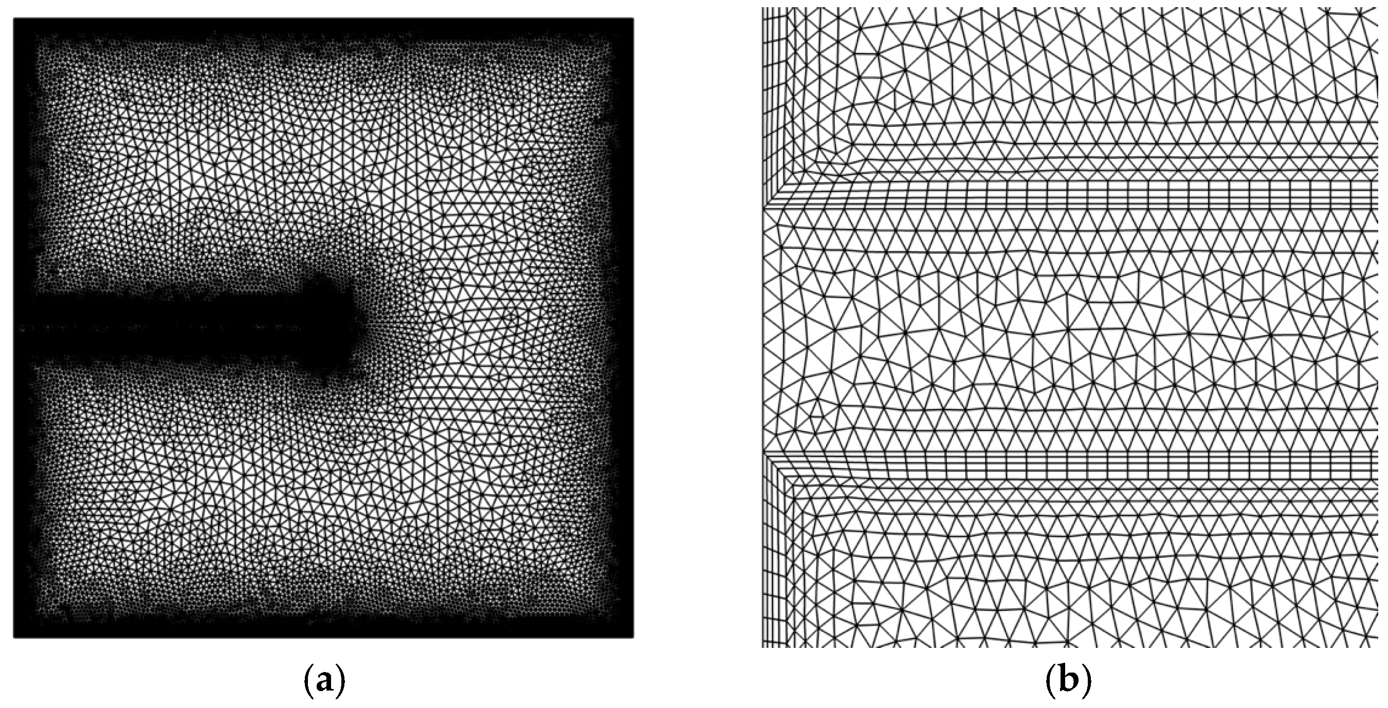
A structured mesh is utilized close to the solid boundaries, featuring four layers with a stretching factor of 1.2 to guarantee adequate boundary layer resolution. The thickness of the first layer is limited to a maximum value of 0.00391, established through the grid independence study, which ensures accurate heat transfer calculations at the solid-fluid interface. An irregular, unstructured mesh is utilized outside the boundary layers to enhance accuracy while ensuring numerical stability. In this area, the maximum element size is specified to be 0.03, and a growth factor of 1.1 is applied to enable a seamless transition from the finely-tuned near-wall region to the coarser mesh in the central domain. This gradual refinement minimizes numerical diffusion while preserving computational efficiency. Figure 2 depicts the mesh structure for a square enclosure featuring a horizontal fin with a thickness of 0.01 and a length of 0.5, placed at Yfin = 0.5. In Figure 2a, the complete computational grid is shown, whereas Figure 2b offers a detailed view of the area where the fin interfaces with the hot wall, emphasizing the locally refined grid designed to address steep thermal gradients. This approach to mesh treatment is consistently utilized throughout the study to guarantee accurate predictions of natural convection phenomena, especially when a fin is present.
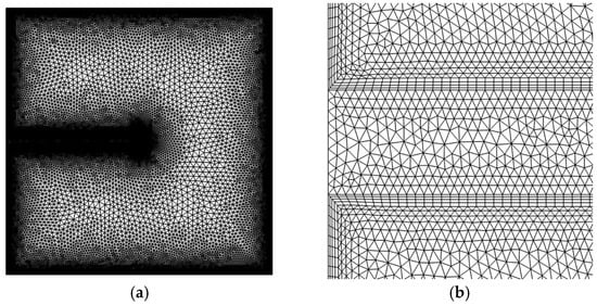
Figure 2.
Mesh for a square enclosure with a fin on the hot wall of 0.01 thickness and 0.5 length (a) full view (b) zoomed view of the region where the fin meets the hot wall.
Although the present study is based on a numerical model, care has been taken to ensure physical consistency and experimental relevance. The assumptions adopted, namely laminar, steady-state, two-dimensional flow, and the Boussinesq approximation, are deliberately selected to isolate fundamental thermal-fluid interactions without introducing additional uncertainties from turbulence or transient effects. This controlled environment allows for a systematic and high-resolution exploration of parameter sensitivities (e.g., fin geometry, fluid properties), which would be extremely difficult to replicate experimentally at scale. Nonetheless, numerous prior studies have experimentally validated the governing phenomena (e.g., natural convection in enclosure-type geometries) under comparable conditions. The results presented here are non-dimensional and thus scalable to practical configurations. Future experimental verification is feasible using cavity-based test rigs with embedded fins, constant-temperature boundary heating, and optical access. Flow fields may be measured using Laser Doppler Velocimetry (LDV), hot-wire anemometry, or Micro-Electro-Mechanical Systems (MEMS) such as those described in [21], while thermal fields can be validated via fine thermocouple arrays or infrared imaging. The present simulations are intended not as a design blueprint but as a reference framework for understanding and optimizing passive heat transfer in laminar enclosures.
4. Results and Discussions
The natural convection problem analyzed in this study is influenced by several parameters, including the Rayleigh number (Ra), Prandtl number (Pr), conductivity ratio (kfin/k), fin length (Lfin), fin thickness (Wfin), and fin position (Yfin). A systematic parametric study was conducted by varying these parameters to investigate their effects on heat transfer and flow behavior within the enclosure. The specific ranges considered for each parameter are summarized in Table 3. The fin thickness (Wfin) is varied from 1 × 10⁻³ to 0.1, meaning that the thermal conductivity of the fin (kfin) significantly influences the heat transfer characteristics. A broad range of conductivity ratios (kfin/k), spanning 1 to 102, is examined to account for this effect. The fin length (Lfin) and its vertical position (Yfin) are varied between 0.1 and 0.9 to assess their impact on the Nusselt number and convective flow structure.
Table 3.
Range of investigated parameters.
These parameter ranges were selected to ensure both physical realism and comprehensive coverage of laminar convection behavior in enclosure-based heat transfer systems. The Rayleigh number range (10 ≤ Ra ≤ 106) captures the full spectrum from conduction-dominated to convection-dominated regimes under laminar conditions. The Prandtl number range (0.1 ≤ Pr ≤ 10) encompasses both thermally diffusive and momentum-dominant fluids, such as liquid metals, water, oils, and refrigerants, thus broadening the applicability of the findings across various engineering contexts.
The geometric parameters of the fin length (Lfin), vertical position (Yfin), and thickness (Wfin) were normalized with respect to the cavity size and varied over wide ranges to systematically assess their influence. Fin lengths between 0.1 and 0.9 were chosen to examine the progressive transition from compact thermal perturbations to near-wall obstructions that span most of the cavity. Short fins allow for minimal disruption to the convective path, whereas longer fins interact significantly with the primary flow structures, particularly at higher Rayleigh numbers. Vertical fin positions from 0.1 to 0.9 capture the effects of placing the fin near the lower boundary layer, at the center of the enclosure (where the primary plume typically develops), or in the upper recirculation zone. This enables the evaluation of how thermal plume interaction and flow symmetry evolve with placement. Fin thicknesses from 10−3 to 10−1 were selected to represent a broad spectrum of practical designs, from slender fins with negligible blockage effects to bulkier fins capable of redirecting flow and storing or diffusing heat. Thicker fins also introduce additional thermal mass and conduction pathways, which influence local gradients and boundary layer reattachment.
The conductivity ratio (kfin/k) was varied across three orders of magnitude (i.e., 1, 10, and 100) to reflect a range of realistic material contrasts. A ratio of 1 represents baseline cases, such as polymeric or composite fins in water or air. Ratios of 10 and 100 approximate scenarios where metallic fins (e.g., aluminum or copper) are used in fluids with significantly lower conductivity (e.g., oils or gases). This allows the study to capture the thermal interaction at the fluid-solid interface under different thermal coupling strengths and to distinguish between diffusion-limited and convection-limited transfer mechanisms. These parameter choices are collectively informed by prior benchmark studies [10,11,12,13,14,15,16] and aligned with real-world thermal system designs, enabling generalizable conclusions and detailed insight into passive enhancement strategies. In particular, the selected ranges are typical of passive thermal systems such as battery enclosures, sealed electronics housings, and solar receivers, where compact fin designs must be optimized for space, conduction efficiency, and minimal flow disruption.
Due to the large number of studied cases, a base case configuration is selected, defined by air as the working fluid (Pr = 0.71), a conductivity ratio of kfin/k = 1, a fin length and vertical position of Lfin = Yfin = 0.5, and a fin thickness of Wfin = 10−2. Each subsequent variation in the parametric study is performed by changing only one parameter at a time, while keeping all others fixed, to isolate its effect on heat transfer and flow dynamics.
The following subsections synthesize the thermal and flow behaviors observed across the studied configurations, highlighting key trends based on Rayleigh and Prandtl numbers and geometric and material variations of the fin. To maintain clarity while preserving the completeness of the parametric analysis, only a subset of representative results is presented in the main text. These include cases with contrasting Rayleigh (Ra) and Prandtl (Pr) numbers that effectively capture the transition from conduction- to convection-dominated regimes and illustrate the influence of thermal diffusivity. The full set of figures, covering all parameter variations across fin length, thickness, position, and conductivity ratio, is available in the Supplementary Materials for reference.
4.1. Heat Transfer Regimes (Low vs. High Ra)
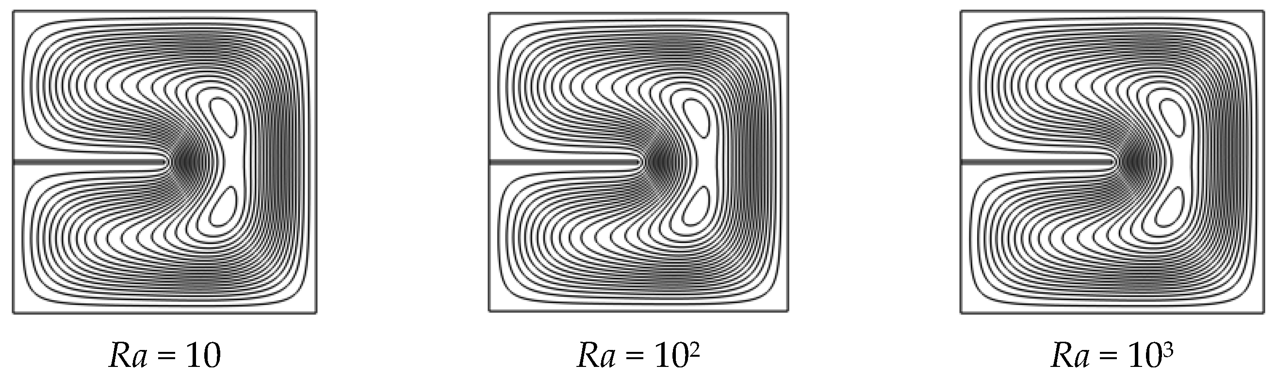
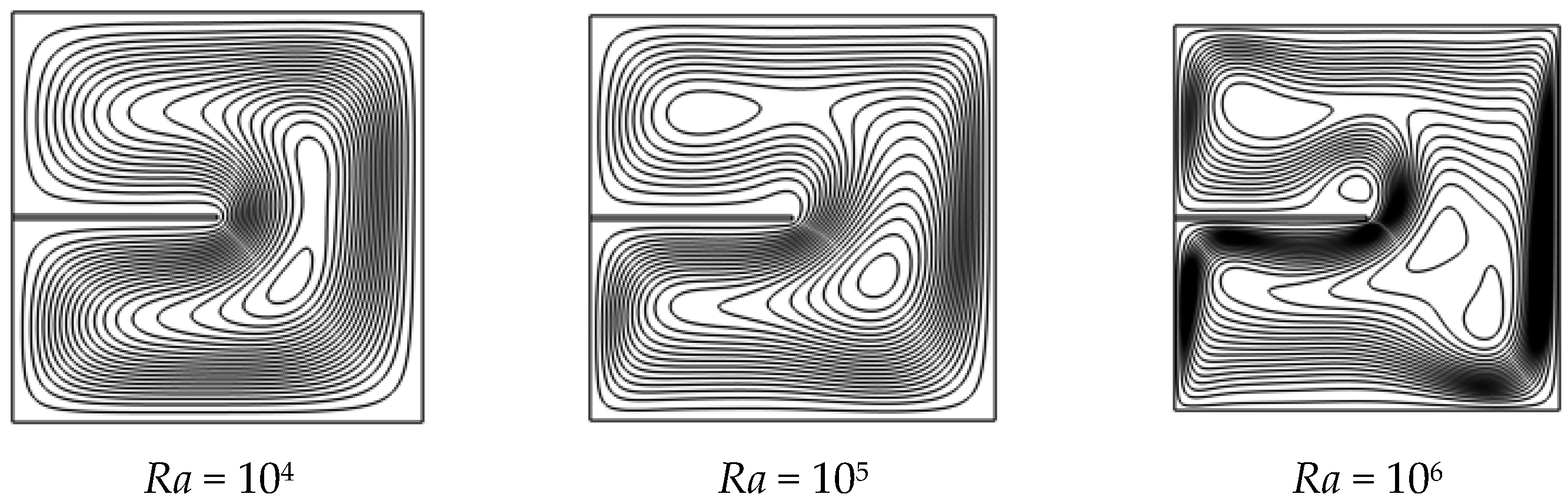
Natural convection within the square enclosure undergoes a significant transformation as the Rayleigh number (Ra) increases, transitioning from a conduction-dominated to a convection-dominated regime. Figure 3 and Figure 4 illustrate the evolution of thermal and flow structures with increasing Ra. The isotherms (Figure 3) capture the thermal stratification across six orders of magnitude of Rayleigh number, while the streamlines (Figure 4) visualize the onset and intensification of natural convection. Together, these plots reveal how convective behavior changes with Rayleigh number and show that the fin increasingly influences heat transfer, having little effect at low Ra but significantly enhancing convection as Ra increases.
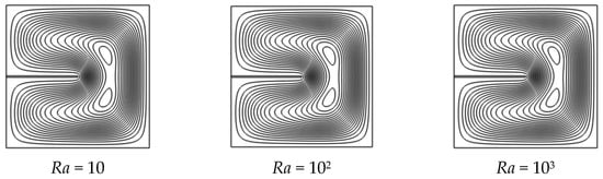

Figure 3.
Streamlines for varying Rayleigh numbers (Ra = 10 to 106) at base case conditions: Pr = 0.71, Yfin = 0.5, Lfin = 0.5, Wfin = 0.01, and kfin/k = 1.
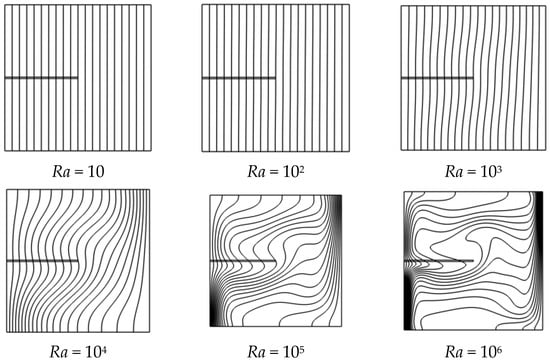
Figure 4.
Isotherms for varying Rayleigh numbers (Ra = 10 to 106) at base case conditions: Pr = 0.71, Yfin = 0.5, Lfin = 0.5, Wfin = 0.01, and kfin/k = 1.
At low Rayleigh numbers (Ra ≤ 102), the flow remains nearly quiescent, and heat transfer is governed primarily by conduction. The presence of a fin has minimal impact in this regime, as observed from the nearly uniform, horizontal isotherms and the absence of any noticeable circulation patterns. This is clearly illustrated in the base case with Pr = 0.71 and various fin positions (see Figure S1), where the fin only induces a mild local perturbation without generating recirculating flow. The heat transfer enhancement is negligible across all geometries (Figures S4 and S7) and positions (Figure S1), and the temperature distribution remains stratified and symmetric.
As the Rayleigh number increases into the intermediate range (Ra = 103 to 104), buoyancy generates weak circulation within the cavity. Isotherms near the hot wall start to bend upward, and the influence of the fin becomes more discernible. In this transitional regime, the fin acts as a localized disturbance that affects the symmetry and structure of the developing plume. For instance, Figures S2 and S5 demonstrate how mid-positioned or extended fins can slightly displace the vortex center and introduce asymmetry. While overall heat transfer increases compared to the conduction regime, the effect of fin geometry on enhancement remains limited but non-negligible.
Natural convection becomes the dominant transport mechanism at higher Rayleigh numbers (Ra ≥ 105), and strong, coherent circulation loops are established. In this regime, the fin has a pronounced impact on both thermal and flow behavior. When placed at mid-height (Yfin = 0.5), the fin reinforces vortex symmetry, promotes thermal mixing, and improves wall heat extraction, particularly in high-Pr fluids. Figures S2 and S5 show the emergence of intense streamlines and secondary vortices induced by the fin, especially when its length or thickness is increased. Figure S8, which illustrates the effect of fin thickness, similarly shows how wider fins intensify local recirculation. These changes in flow structure directly correlate with higher local and global heat transfer rates.
These results confirm that the effectiveness of a fin is highly regime-dependent. In conduction-dominated settings (low Ra), geometry has negligible influence. In contrast, in convection-dominated regimes (high Ra), thoughtful selection of fin position and size significantly enhances performance. This understanding is crucial for the design of passive cooling systems tailored to operate efficiently under specific thermal loads and enclosure conditions.
The local Nusselt number (Nuloc) distribution along the heated wall further illustrates the transition between thermal regimes and the evolving role of the fin. At low Rayleigh numbers (e.g., Ra = 10 and 102), Nuloc remains nearly uniform and low in magnitude, confirming conduction dominance with minimal fin-induced enhancement. This is evident in Figure S3, where flat profiles and minimal spatial gradients reflect the weak thermal gradients near the wall. As Ra increases to intermediate values (Ra = 103–104), localized peaks begin to emerge near the fin tip or attachment region, indicating the initial influence of convective motion. These localized intensifications correspond to the onset of buoyancy-driven separation and plume deflection.
At higher Rayleigh numbers (Ra ≥ 105), the Nuloc profiles develop sharper gradients and multiple peaks, especially near the upper and lower corners of the hot wall, signaling strong thermal boundary layers and vigorous convection. The presence of the fin significantly reshapes these distributions depending on its geometry and placement. For example, Figure S9 highlights how mid-positioned and moderately thick fins produce symmetric enhancement zones along the wall, while suboptimal placements lead to skewed or split profiles. Figure S3 similarly shows the effect of fin position on Nuloc symmetry. Figure S12 further demonstrates that increasing the fin’s thermal conductivity amplifies these enhancement zones, especially near the fin base, confirming the additional role of material properties in modulating wall heat extraction. These localized heat transfer variations reflect complex interactions between the fin-induced disturbance and natural plume evolution. The analysis of Nuloc thus reinforces the conclusion that optimal heat transfer performance arises from careful tuning of the fin’s interaction with buoyant flow.
4.2. Influence of Prandtl Number on Flow Structure and Thermal Response
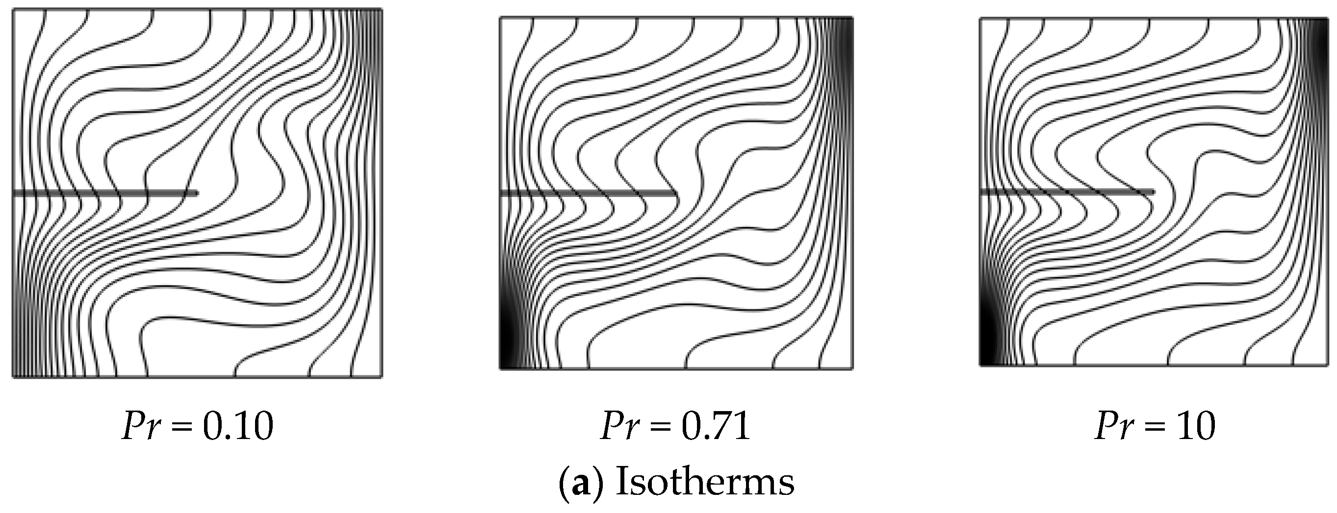
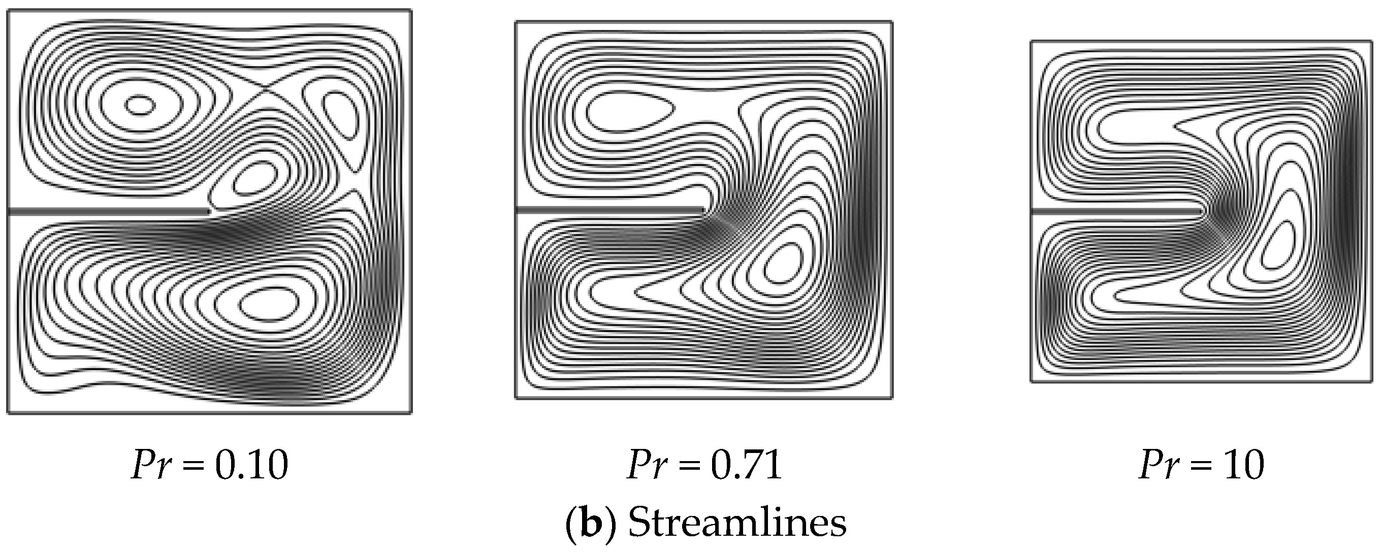
Figure 5 illustrates how varying the Prandtl number (Pr = 0.1, 0.71, and 10) at fixed Ra = 105 affects natural convection. Heat diffuses rapidly at low Pr (0.1), resulting in smooth isotherms and weak recirculation. The fin has minimal influence due to the dominance of thermal diffusion. For Pr = 0.71 (air), convection strengthens, with clear vortex formation and the fin enhancing plume curvature and mixing. At high Pr (10), the flow becomes sharply localized, boundary layers thin, and the fin induces strong secondary vortices and plume redirection.


Figure 5.
Isotherms and streamlines for varying Pr numbers (Pr = 0.1 to 10) and Ra = 105 at base case conditions: Pr = 0.71, Yfin = 0.5, Lfin = 0.5, Wfin = 0.01, and kfin/k = 1.
Overall, higher Prandtl numbers increase the fin’s thermal influence by reinforcing boundary layer interactions and flow symmetry. This demonstrates that fin design must be tailored to the thermo-physical properties of the fluid to achieve effective thermal enhancement.
At low Prandtl numbers (Pr ≈ 0.1), thermal diffusion is dominant, and heat spreads more uniformly throughout the enclosure. Figures S1, S4 and S7 show that the isotherms are smoother, with weaker temperature gradients near the hot wall. The velocity field, however, remains sluggish due to high thermal diffusivity and low momentum diffusion, leading to broad, weak recirculation zones. This is further illustrated in the streamline plots (Figures S2, S5 and S8), where the flow intensity is low and the vortices are diffuse. The influence of the fin in such cases is minimal, especially at low Ra, and any flow disruption caused by the fin dissipates quickly due to strong thermal diffusion.
The momentum and thermal diffusivities are comparable as the Prandtl number increases to unity (Pr ≈ 1). This is characteristic of air and similar fluids and forms the baseline scenario in many natural convection studies. In this regime, the boundary layers are well coupled, and the fin begins to affect both the temperature field and flow structure. Figures S2, S5 and S8 show intensified vortex formation and stronger recirculation in the presence of fins, particularly when they are placed at mid-height or have greater thickness. Complementary isotherm plots in Figures S1, S4 and S7 reveal corresponding curvature in thermal contours, indicating enhanced mixing and thermal disruption. Although vortex structures remain relatively symmetric in this regime, fin geometry variations and Prandtl number induce mild asymmetries.
At higher Prandtl numbers (Pr = 10), representing more viscous fluids such as oils or refrigerants, momentum diffusion dominates, resulting in thinner thermal boundary layers and stronger buoyancy-induced flow. Figures S2, S5 and S8 reveal that under these conditions, the fin dramatically alters the internal circulation, inducing sharp thermal gradients and well-defined vortex cores. Figures S1, S4 and S7 further illustrate sharper isotherm bending and steeper thermal gradients near the fin, especially when its position or thickness is varied. The thermal plume becomes highly sensitive to fin location and thickness, with increased enhancement in localized heat transfer and significant deformation of the flow pattern.
Importantly, the effect of fin geometry becomes more pronounced at higher Pr. While low-Pr cases show diffusive behavior that masks geometric variations, high-Pr scenarios amplify the influence of each design change. For example, increasing the fin thickness at Pr = 10 leads to intensified secondary vortices (Figure S8) and sharper temperature stratification near the heated wall (Figure S7), while in low-Pr cases, the same change yields only marginal differences.
The Prandtl number governs the relative strength and scale of flow structures and heat transfer gradients. Fins are more effective in high-Pr fluids, interacting with thinner thermal boundary layers and enhancing mixing and wall heat extraction. Figures S2, S5 and S8 demonstrate stronger recirculation zones at Pr = 10, while Figures S1, S4 and S7 show sharper isotherm bending and localized temperature stratification. In contrast, low-Pr fluids exhibit dominant thermal diffusion, and geometric changes produce only mild flow and thermal effects. These findings highlight the importance of aligning fin design not only with geometric considerations but also with the thermo-physical properties of the working fluid.
The influence of Prandtl number (Pr) on local Nusselt number (Nuloc) distributions provides additional insight into how thermal and momentum diffusivities shape surface heat transfer. For low-Pr fluids (e.g., Pr = 0.1), the Nuloc profiles exhibit broad, low-amplitude distributions, reflecting thick thermal boundary layers and sluggish thermal gradients. This behavior is evident in Figure S3, where Nuloc remains subdued and diffuses along the heated wall regardless of Ra. As Pr increases to moderate values (e.g., Pr = 1), sharper peaks form near the fin and at the cavity corners, indicating a more vigorous thermal response and tighter boundary layer confinement. These trends are also visible in Figure S6, particularly in cases with longer fins, where peak localization becomes more pronounced.
High-Pr fluids (Pr = 10) produce the most pronounced Nuloc enhancement, with steep gradients and multiple localized maxima corresponding to plume detachment, fin-tip intensification, and corner effects. These profiles, shown in Figures S9 and S12, demonstrate the combined impact of stronger thermal layering and the fin’s ability to redirect the thermal plume. Notably, mid-height fin placements in high-Pr cases generate well-defined Nuloc peaks that coincide with enhanced mixing and symmetric recirculation zones. This Pr-dependent modulation of Nuloc demonstrates that surface heat transfer depends not only on the geometry but also fundamentally on the fluid’s thermo-physical properties of the working fluid.
4.3. Effect of Fin Geometry and Material
The thermal effectiveness of a fin depends not only on its material properties but also on its geometric attributes, specifically its vertical position, length, and thickness. These factors determine how the fin interacts with thermal boundary layers and convective flow patterns. This section presents a detailed parametric analysis of these three aspects, followed by the role of thermal conductivity.
4.3.1. Fin Position (Yfin)
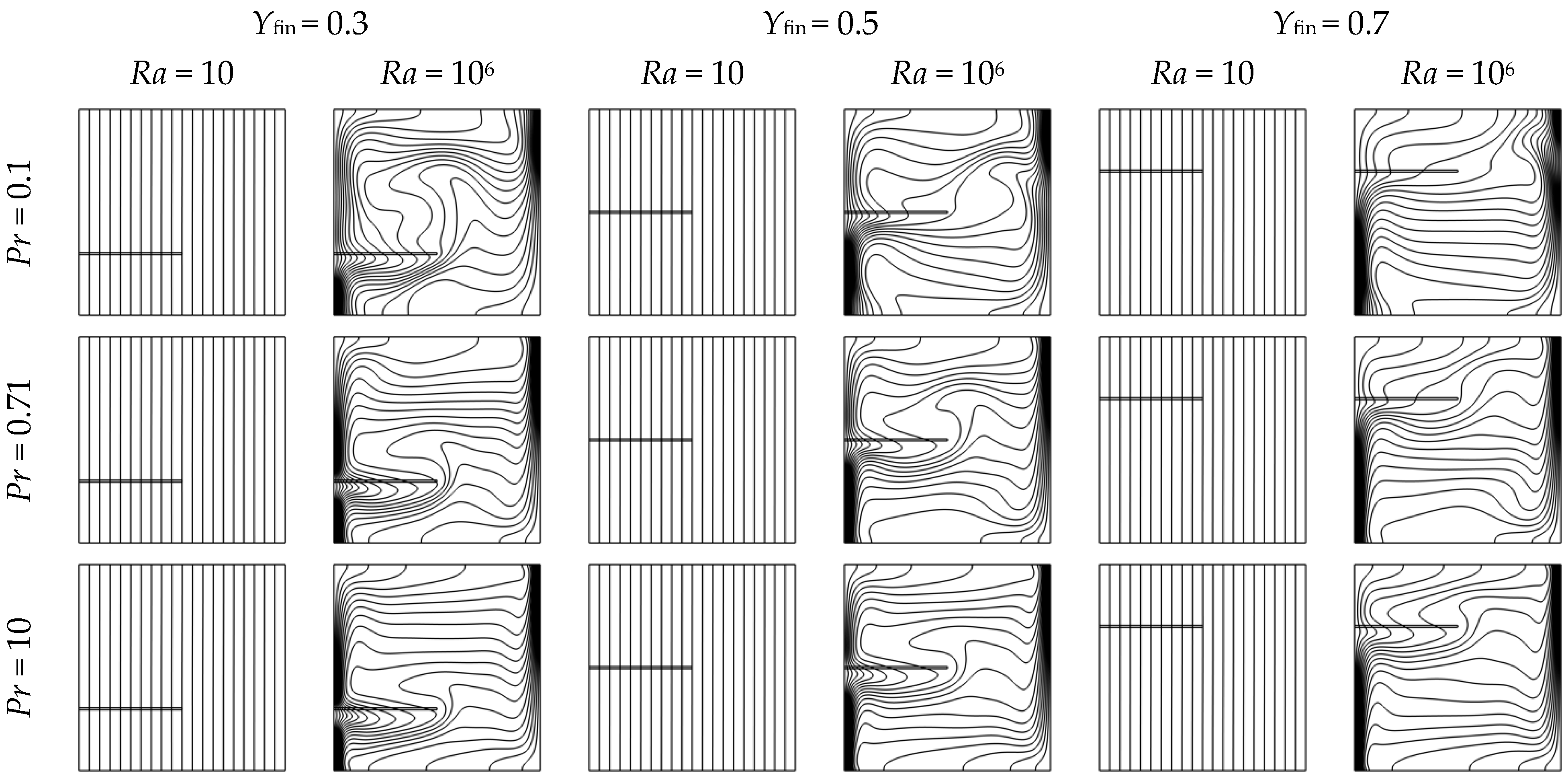
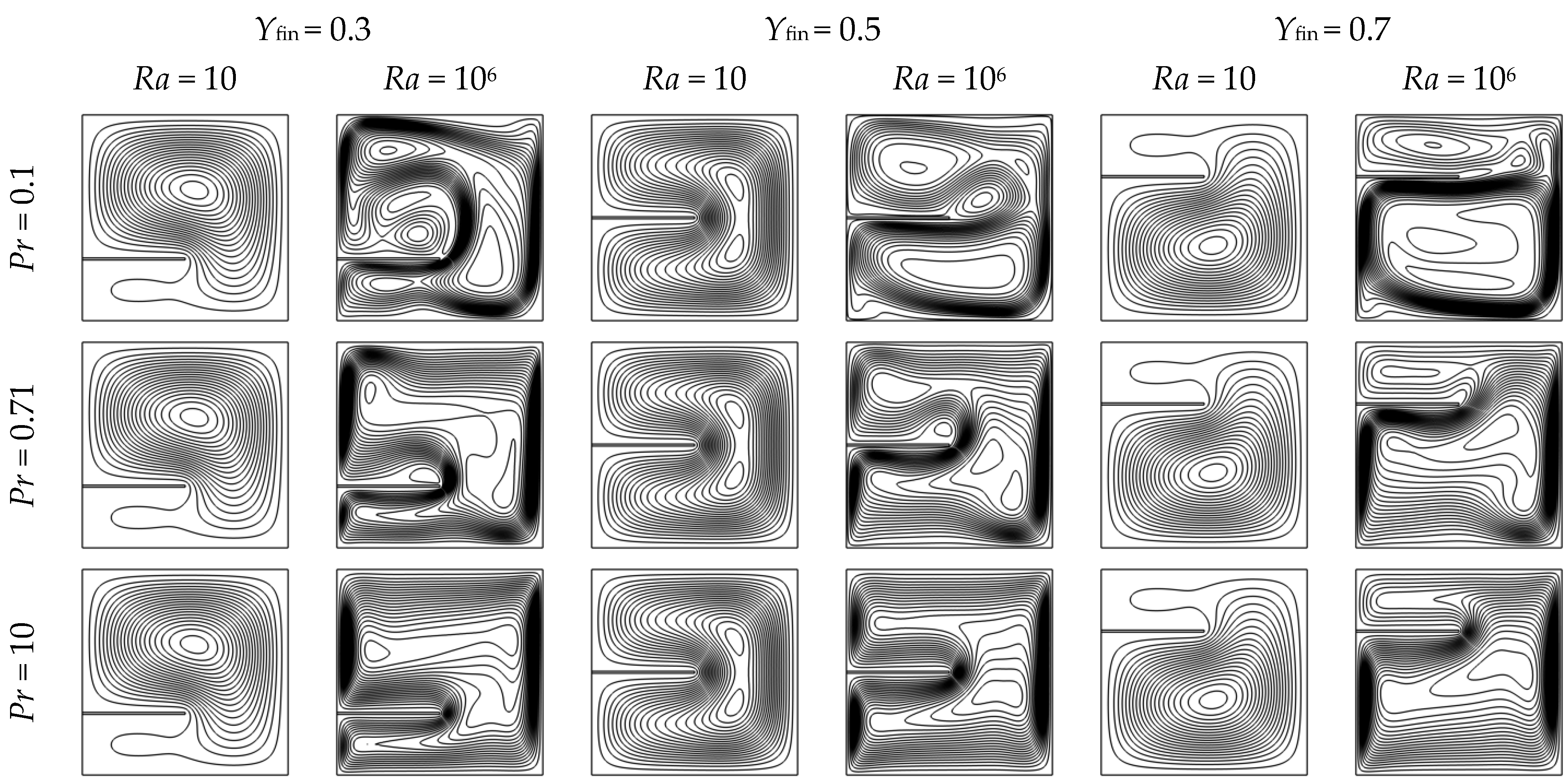
The fin’s position significantly impacts flow symmetry and the behavior of thermal plumes in natural convection. Three different fin placements, near the bottom (Yfin = 0.3), in the center (Yfin = 0.5), and at the top (Yfin = 0.7), were evaluated across a range of Rayleigh and Prandtl numbers.
Positioning the fin at mid-height (Yfin = 0.5) aligns it with the core thermal plume, which enhances vortex symmetry, strengthens circulation, and improves thermal extraction from the hot wall. Conversely, locating the fin near the bottom (Yfin = 0.3) interferes with early plume development and creates secondary flow zones, whereas placement at the top (Yfin = 0.7) engages only minimally with the main circulation due to reduced buoyant momentum.
Figure 6 (isotherms) and Figure 7 (streamlines) illustrate these effects for Ra = 10 and 106, across Pr = 0.1, 0.71, and 10. The figures demonstrate that the central position optimizes heat transfer enhancement through effective coupling with the primary convective structure.
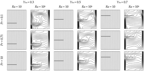
Figure 6.
Isotherms in a square enclosure with a horizontal fin at three vertical positions (Yfin = 0.3, 0.5, and 0.7), for Rayleigh numbers Ra = 10 and 106, and Prandtl numbers Pr = 0.1, 0.71, and 10. Other parameters are fixed: Lfin = 0.5, Wfin = 0.01, and kfin/k = 1.
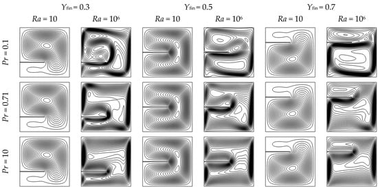
Figure 7.
Streamlines in a square enclosure with a horizontal fin at three vertical positions (Yfin = 0.3, 0.5, and 0.7), for Rayleigh numbers Ra = 10 and 106, and Prandtl numbers Pr = 0.1, 0.71, and 10. Other parameters are fixed: Lfin = 0.5, Wfin = 0.01, and kfin/k = 1.
When the fin is placed near the bottom (Yfin = 0.3), it directly interferes with the early development of the thermal plume, particularly at higher Rayleigh numbers. As shown in Figure S2, this interference often results in an upward shift of the primary vortex and the formation of secondary circulation zones. Figure S3 further shows that this configuration can reduce the local Nusselt number near the fin region, indicating diminished heat transfer efficiency despite the increased surface area.
At mid-height (Yfin = 0.5), the fin intersects the core of the ascending thermal plume, promoting a more symmetric interaction with buoyant flow. This configuration enhances thermal mixing and supports balanced heat extraction along the hot wall. Figure S2 shows that this position often leads to well-structured vortex pairs on either side of the fin, particularly at higher Rayleigh numbers. Although Figure S3 shows that local Nusselt numbers at Yfin = 0.5 are generally moderate, their spatial distribution tends to be more uniform than at other positions, especially in high-Pr fluids. This consistency makes mid-height fins a robust choice across a range of convective regimes.
When the fin is placed near the top (Yfin = 0.7), it has limited influence on the main convective structure. By this height, the thermal plume is well-established, and the fin primarily interacts with weaker recirculatory motion near the upper wall. Figures S1 and S2 show minimal distortion in isotherms and streamlines, indicating weak flow disruption. Figure S3 further confirms that local Nusselt number enhancement is modest and confined to the immediate vicinity of the fin tip, with little impact on the broader heat transfer performance.
Table S2 summarizes the variation of the Normalized Nusselt Ratio (NNR) with fin position across different Rayleigh and Prandtl numbers, offering a consolidated perspective on how vertical placement influences heat transfer. At low Ra (≤102), the NNR remains close to unity across all Yfin values, confirming the negligible effect of the fin in conduction-dominated regimes. As Ra increases (Ra ≥ 104), more distinct patterns emerge: placing the fin near the mid-height (Yfin = 0.5) often yields the highest NNR across a broad range of Prandtl numbers, especially at Ra = 106. This behavior reflects optimal alignment with the thermal plume and enhanced symmetry in vortex formation. While Yfin = 0.7 occasionally performs well in certain Pr–Ra combinations, its effectiveness is less consistent than the mid-height configuration.
In contrast, fins placed near the cavity’s top (Yfin = 0.7) or bottom (Yfin = 0.3) show reduced NNRs, particularly at high Ra and low Pr, due to misalignment with dominant flow structures. For example, bottom-placed fins tend to obstruct upward plume development, while top-placed fins interact less efficiently with the primary vortex, as reflected in Figure S2. These findings underscore the strong regime dependence of fin placement effectiveness and demonstrate that optimal positioning enhances local flow patterns and overall system-level thermal performance as quantified by NNR.
Placing the fin at Yfin = 0.5 often provides a balanced trade-off between interacting with the core thermal plume and maintaining flow symmetry. This mid-height configuration promotes more organized vortex structures, particularly at high Prandtl numbers. Although it does not always yield the highest Nusselt ratio across all Ra and Pr combinations (Table S2), it performs consistently well and represents a reliable compromise between thermal access and flow disturbance.
4.3.2. Fin Length (Lfin)
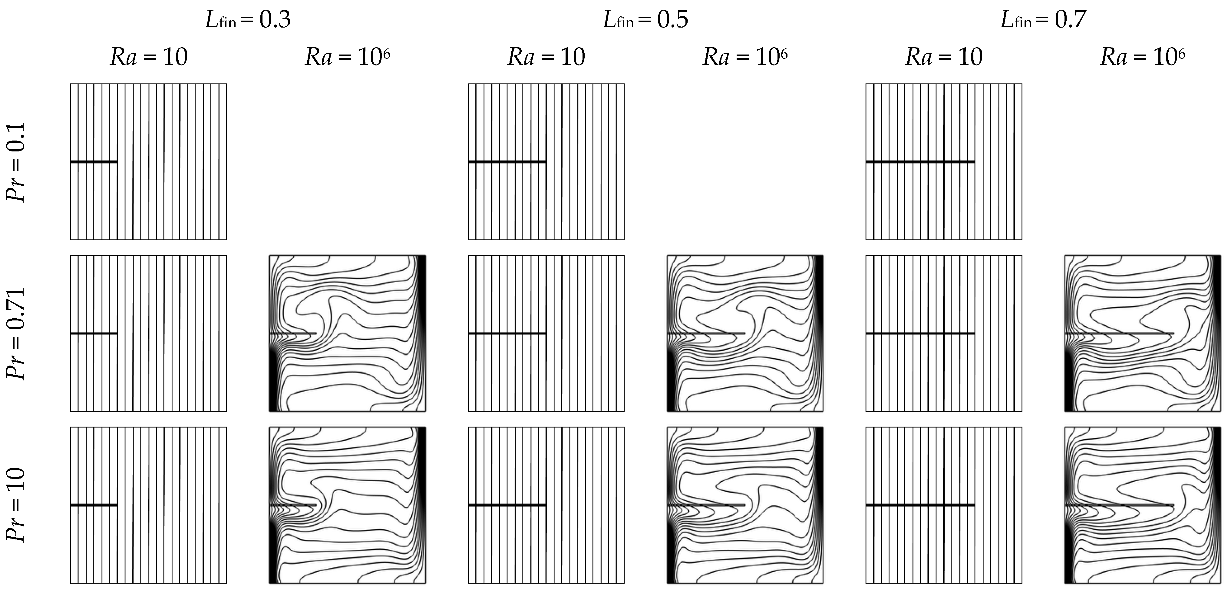
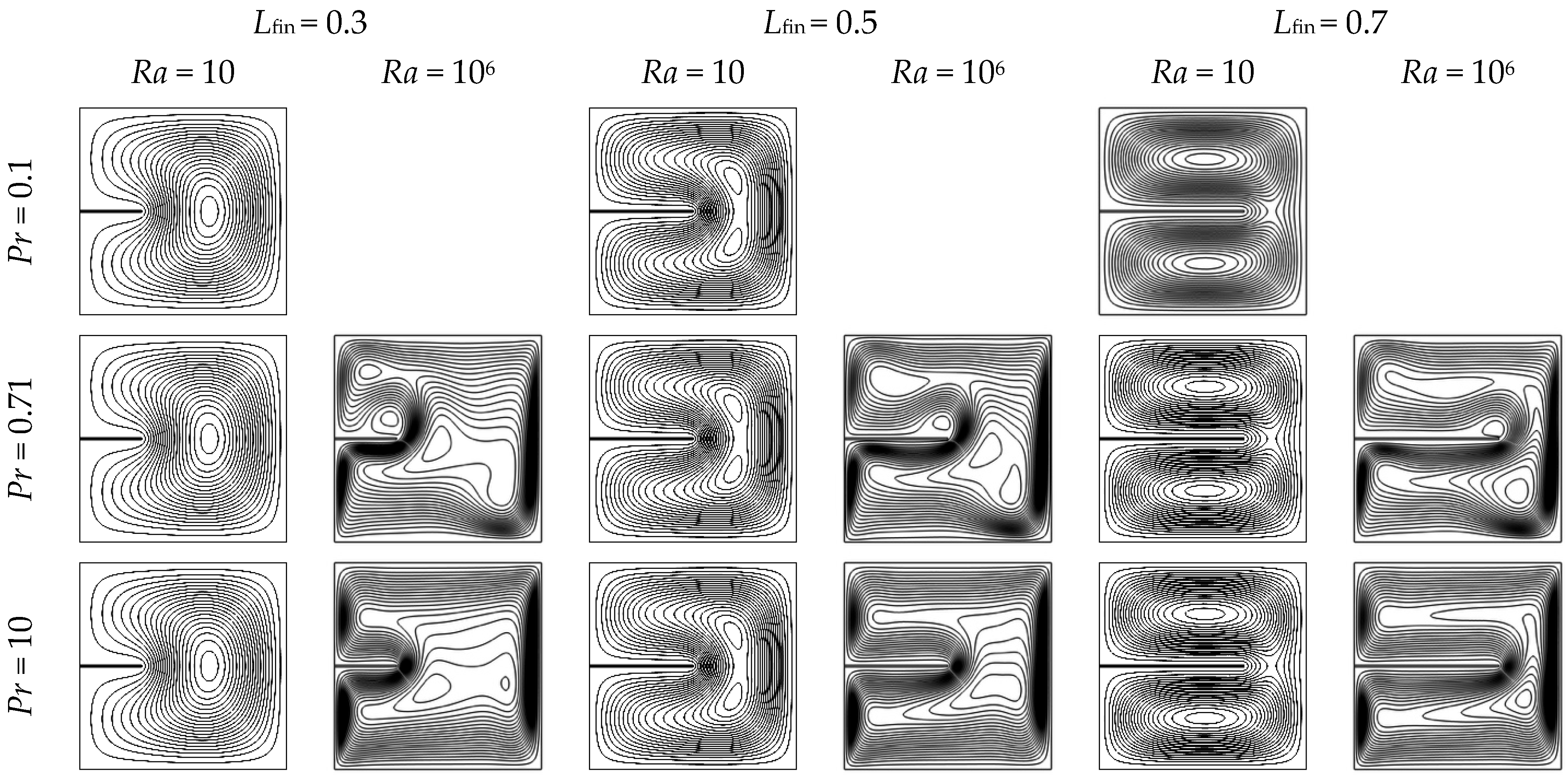
The length of the fin directly influences how it interacts with the thermal boundary layer and the convective flow field. Figure 8 and Figure 9 illustrate that fin lengths of Lfin = 0.3, 0.5, and 0.7 generate unique thermal and flow patterns at Ra = 10 and 106, across Pr = 0.1, 0.71, and 10.
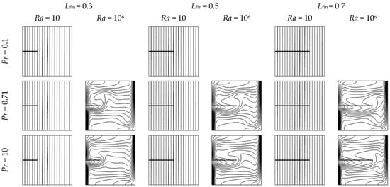
Figure 8.
Isotherms in a square enclosure with a horizontal fin of three different lengths (Lfin = 0.3, 0.5, and 0.7), for Rayleigh numbers Ra = 10 and 106, and Prandtl numbers Pr = 0.1, 0.71, and 10. Other parameters are fixed: Yfin = 0.5, Wfin = 0.01, and kfin/k = 1.
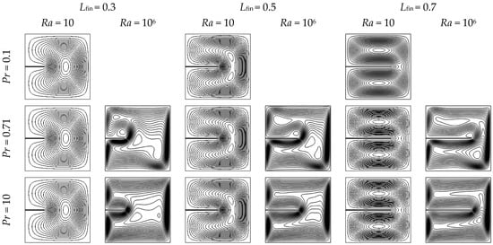
Figure 9.
Streamlines in a square enclosure with a horizontal fin of three different lengths (Lfin = 0.3, 0.5, and 0.7), for Rayleigh numbers Ra = 10 and 106, and Prandtl numbers Pr = 0.1, 0.71, and 10. Other parameters are fixed: Yfin = 0.5, Wfin = 0.01, and kfin/k = 1.
Short fins (Lfin = 0.3) cause slight disturbances in the near-wall flow, enhancing local heat extraction while minimally impacting global circulation. Moderate-length fins (Lfin = 0.5) improve mixing and heat transfer by extending deeper into the convective core. In contrast, longer fins (Lfin = 0.7) hinder plume formation and split the primary vortex, resulting in stagnation zones and decreased thermal performance, particularly at high Ra.
The findings highlight that moderate fin lengths (Lfin ≈ 0.3–0.5) achieve the optimal balance between thermal improvement and reduced flow disturbance.
At low Rayleigh numbers (Ra ≤ 102), where conduction dominates heat transfer, changes in fin length have minimal impact. The isotherms remain nearly vertical and undistorted, indicating a passive thermal field. As shown in Figure S4, the increased surface area from longer fins does not enhance heat transfer since the fluid remains largely stagnant and convective mechanisms are absent.
However, as Ra increases (Ra ≥ 104) and buoyancy forces drive more intense circulation, the impact of fin length becomes significant. Short fins (Lfin ≤ 0.3) introduce only mild disturbances, improving local heat extraction by accelerating fluid motion near the wall without impeding global flow. Shorter fins also allow smooth streamline continuity near the heated wall, avoiding adverse pressure gradients or flow bifurcation, thus maintaining efficient upward thermal transport. In contrast, long fins (Lfin ≥ 0.7) penetrate deeply into the cavity and often obstruct the main thermal plume, resulting in flow bifurcation, formation of additional vortices, and occasionally flow stagnation zones beneath the fin.
Figure S5 illustrates this transition, showing that as the fin extends beyond Lfin ≈ 0.5, the symmetry of the streamline pattern deteriorates and thermal performance may plateau or decline depending on the Prandtl number. Optimal fin lengths were found to lie in the range Lfin = 0.3 to 0.5, maximizing enhancement while minimizing adverse flow interaction.
Table S3 presents the variation of the normalized Nusselt ratio (NNR) with fin length across a range of Rayleigh and Prandtl numbers, enabling a clear assessment of how extending the fin influences thermal performance. At low Rayleigh numbers, the NNR remains nearly constant across all fin lengths, confirming the limited impact of fin geometry in conduction-dominated regimes. As Ra increases, particularly beyond 104, fin length becomes critical. Moderate fin lengths (Lfin ≈ 0.3–0.5) generally yield higher NNRs across most Pr values, offering a favorable trade-off between increased surface area and minimal obstruction of buoyant flow.
Conversely, excessively long fins (Lfin ≥ 0.7) often reduce the NNR, especially at high Ra, as they interfere with the upward thermal plume and hinder circulation. This degradation is clearly observed in Figure S5, where longer fins split or deflect the main vortex structure, leading to flow asymmetry and reduced thermal extraction from the hot wall. This performance drop is more pronounced at moderate Prandtl numbers (e.g., Pr = 0.71 and 7), whereas high-Pr fluids retain some convective enhancement due to stronger thermal boundary layer coupling. These results emphasize that optimal fin length is highly sensitive to the convection regime and fluid properties, and that overly long fins may become counterproductive in strongly convective enclosures.
4.3.3. Fin Thickness (Wfin)
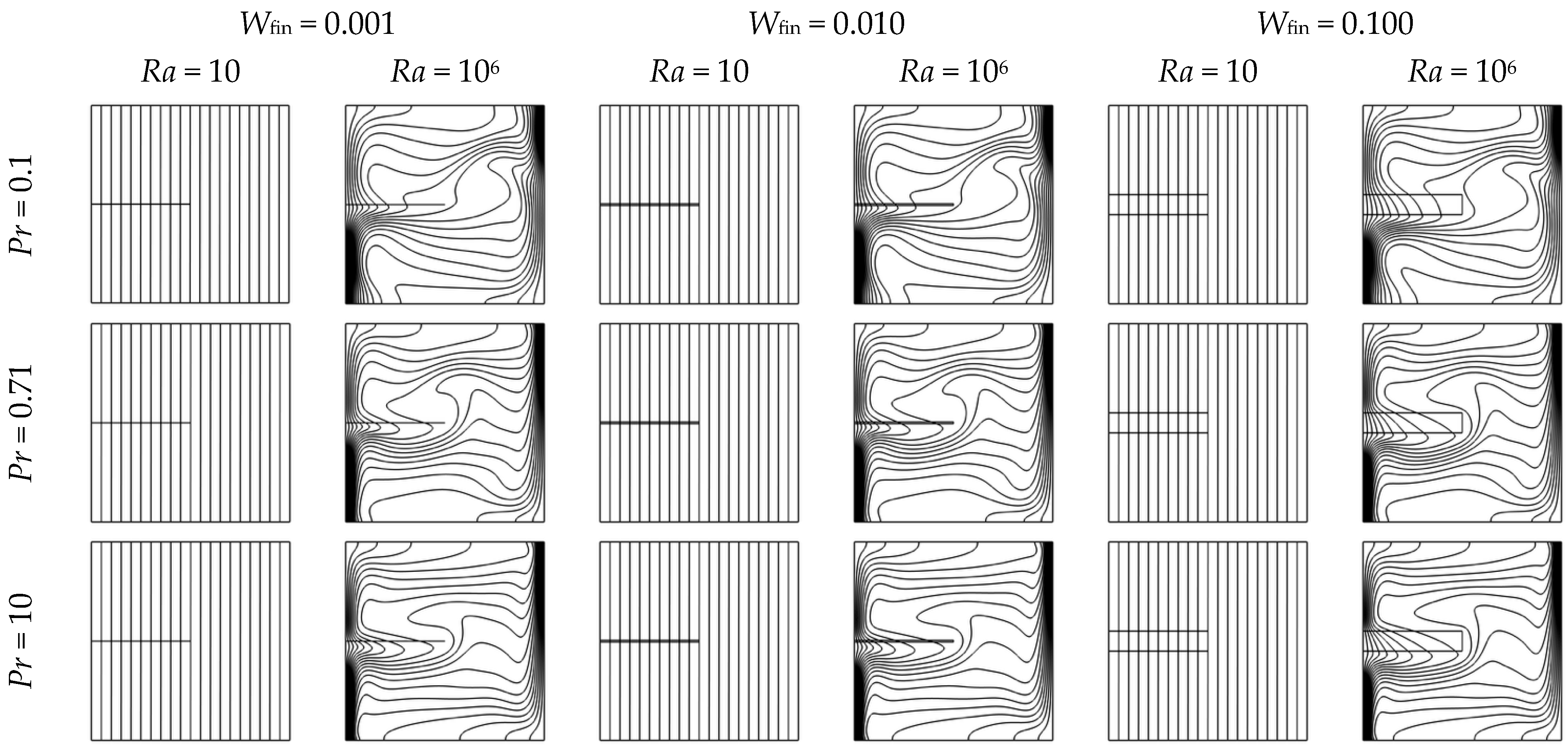
The fin thickness (Wfin) has a dual function, affecting both thermal conduction and hydrodynamic resistance. Figure 10 and Figure 11 display isotherms and streamlines for Wfin values of 0.001, 0.01, and 0.1 at Rayleigh numbers of 10 and 106, across Prandtl numbers of 0.1, 0.71, and 10. At low Rayleigh numbers (Ra ≤ 102), where conduction dominates, variations in Wfin exert little influence on heat transfer or flow behavior. As Ra increases to 106, the influence of Wfin becomes much more pronounced.
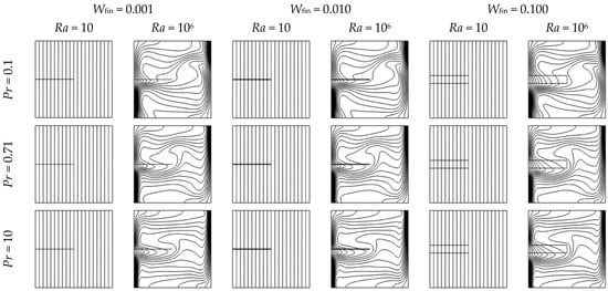
Figure 10.
Isotherms in a square enclosure with a horizontal fin of three different thicknesses (Wfin = 0.001, 0.01, and 0.1), for Rayleigh numbers Ra = 10 and 106, and Prandtl numbers Pr = 0.1, 0.71, and 10. Other parameters are fixed: Yfin = 0.5, Lfin = 0.5, and kfin/k = 1.
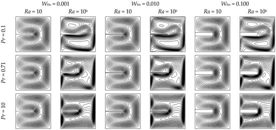
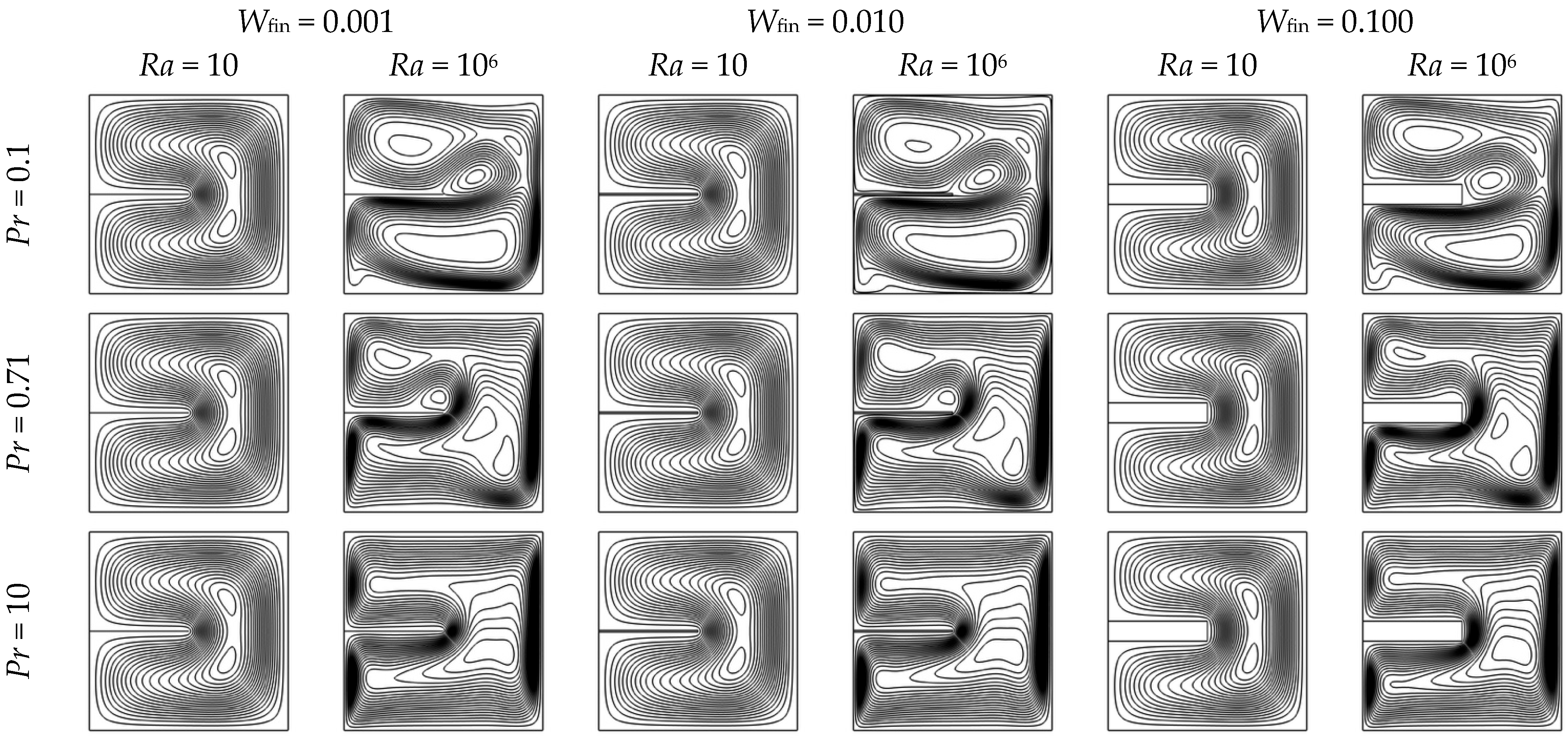
Figure 11.
Streamlines in a square enclosure with a horizontal fin of three different thicknesses (Wfin = 0.001, 0.01, and 0.1), for Rayleigh numbers Ra = 10 and 106, and Prandtl numbers Pr = 0.1, 0.71, and 10. Other parameters are fixed: Yfin = 0.5, Lfin = 0.5, and kfin/k = 1.
Very thin fins (Wfin = 0.001) cause minimal flow disruption and slightly affect the plume structure; however, their small surface area limits heat conduction into the fluid. Moderate-thickness fins (Wfin ≈ 0.01) increase the heat transfer interface while maintaining coherent circulation, thus improving thermal penetration into the bulk flow and raising Nusselt numbers. In contrast, thick fins (Wfin = 0.1) hinder flow by dividing the domain, disrupting the vortex core, and creating stagnation zones, particularly in low-Prandtl-number fluids where momentum diffusivity is predominant and convective strength is lower.
Figure 10 and Figure 11 illustrate these effects clearly. The isotherms in Figure 10 indicate improved thermal layering at moderate Wfin, whereas the streamlines in Figure 11 demonstrate a rise in recirculation and vortex strength, but only to a certain extent. Once Wfin reaches or exceeds 0.05, the streamlines begin to split and symmetry breaks down, suggesting flow obstruction and a drop in global heat transfer.
This trend is notably prominent at moderate-to-high Ra (≥104), where convection is the primary process. A fin of moderate fin thickness optimally enhances thermal diffusion into the active flow while minimally affecting the continuity of the boundary layer. The flow exhibits heightened sensitivity to geometric influences in fluids with high Prandtl numbers and thinner thermal boundary layers. Figure S9 demonstrates that thicker fins create significant shear gradients and lead to the formation of secondary vortices, disrupting the coherence of vertical plumes. In contrast, very thin fins do not significantly engage with the boundary layer due to their minimal surface projection.
Table S4 illustrates the normalized Nusselt ratio (NNR) variation across different Wfin values. In conduction-dominated flows (Ra ≤ 102), the NNR stays close to unity for all Wfin values, indicating that thermal geometry exerts minimal influence. As Ra increases, moderate fin thicknesses (Wfin = 0.01–0.03) consistently yield the highest NNRs, effectively balancing conductive enhancement with convective compatibility. Conversely, overly thick fins (Wfin ≥ 0.07) decrease NNR due to the compression of flow lanes and the establishment of plume bifurcation, as illustrated in Figures S8 and S9. These structures disrupt mixing and generate dead zones that inhibit recirculation.
These results indicate that the optimal fin thickness lies within a moderate range (Wfin ≈ 0.01), where the fin provides sufficient surface area for effective heat conduction without obstructing convective flow. Excessively thick fins (Wfin ≥ 0.1) tend to disrupt the boundary layer and induce vortex asymmetry, while very thin fins (Wfin = 0.001) offer minimal enhancement due to limited thermal contact. As demonstrated in Table S4, the normalized Nusselt ratio (NNR) serves as a reliable design metric, capturing the trade-off between thermal augmentation and hydrodynamic disturbance. This makes NNR a valuable criterion for selecting Wfin across various Rayleigh and Prandtl number conditions.
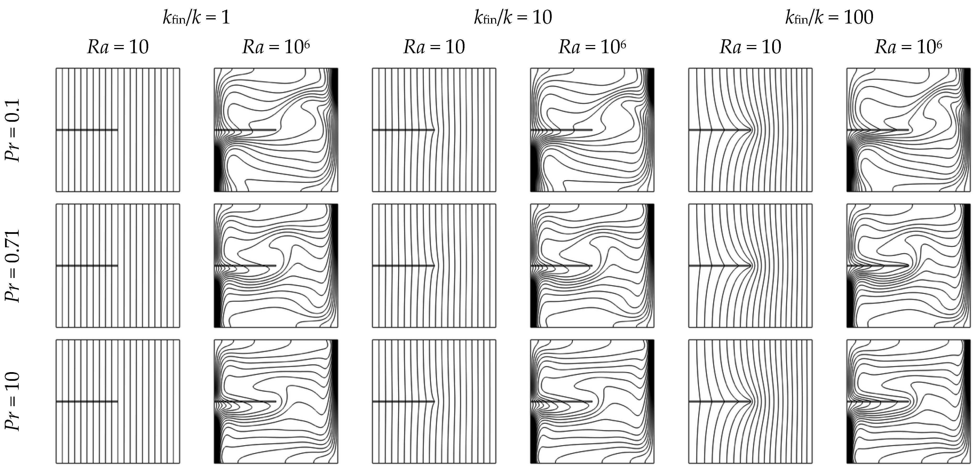
4.3.4. Thermal Conductivity Ratio (kfin/k)
The thermal conductivity ratio between the fin and the fluid medium (kfin/k) critically governs the fin’s ability to bridge heat from the hot wall into the convective core. Figure 12 and Figure 13 illustrate the isotherms and streamlines for kfin/k values of 1, 10, and 100 under fixed geometric conditions and varying Rayleigh (Ra = 10 and 106) and Prandtl numbers (Pr = 0.1, 0.71, and 10).

Figure 12.
Isotherms in a square enclosure with a horizontal fin for three thermal conductivity ratios (kfin/k = 1, 10, and 100), for Rayleigh numbers Ra = 10 and 106, and Prandtl numbers Pr = 0.1, 0.71, and 10. Other parameters are fixed: Yfin = 0.5, Lfin = 0.5, and Wfin = 0.01.
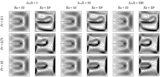
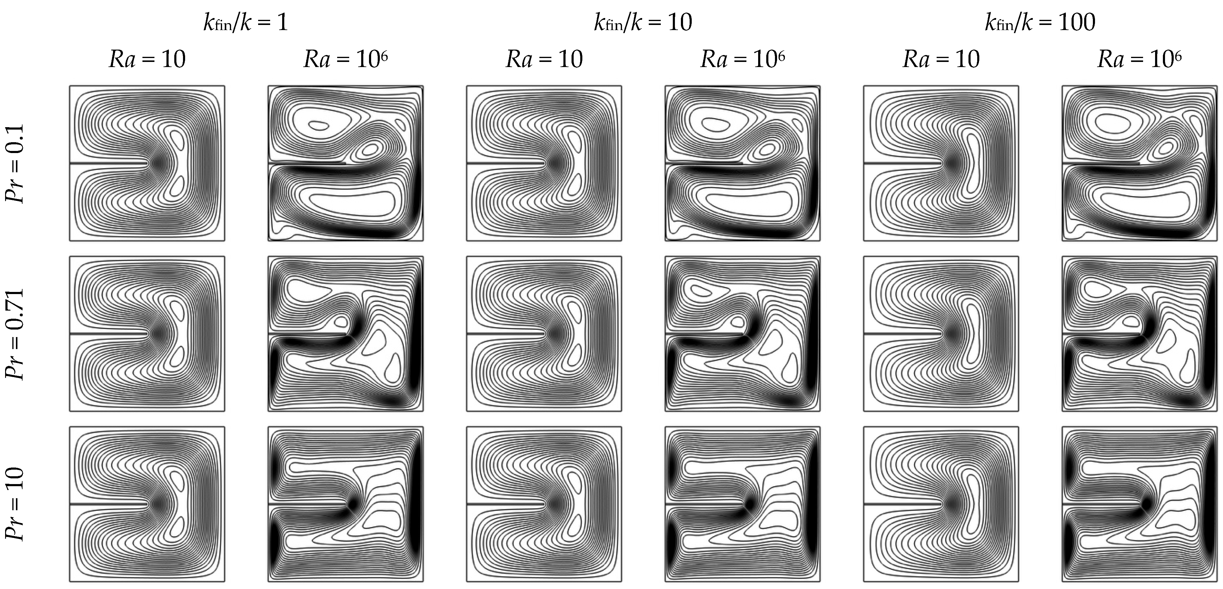
Figure 13.
Streamlines in a square enclosure with a horizontal fin for three thermal conductivity ratios (kfin/k = 1, 10, and 100), for Rayleigh numbers Ra = 10 and 106 and Prandtl numbers Pr = 0.1, 0.71, and 10. Other parameters are fixed: Yfin = 0.5, Lfin = 0.5, and Wfin = 0.01.
When the conductivity ratio is lowest (kfin/k = 1), the fin functions mainly as a passive obstruction instead of a heat conductor. The temperature distribution exhibits minimal penetration into the area, while the streamlines stay mostly unchanged due to the absence of thermal energy moving through the fin. In this scenario, the fin’s impact is restricted to slight disruptions in the flow field, contributing little to the overall heat transfer.
When kfin/k rises to 10, the fin operates as an active thermal conduit. The increased conductivity aids in the lateral distribution of heat along the fin body, leading to sharper thermal gradients at the fin tip. This ignites localized buoyancy-driven acceleration and encourages vortex formation at the fin–fluid interface, particularly under high-Pr and high-Ra conditions. Isotherms become tighter near the hot wall, and secondary vortical structures appear downstream of the fin, signaling enhanced convective interaction.
Increasing the kfin/k ratio to 100 amplifies the heat transfer from the hot wall into the cavity, intensifying thermal diffusion along the fin and steepening local temperature gradients. However, the incremental gains in convective enhancement begin to plateau as the fluid’s ability to transport the additional heat becomes a limiting factor. Although Figures S10 and S11 show more stratified isotherms and greater curvature in streamlines, the bulk circulation strength remains largely unchanged, particularly in low-Prandtl-number fluids, where thermal diffusion dominates over momentum transport. This saturation effect suggests that beyond a conductivity ratio of ~100, further increases yield diminishing returns, as the fin becomes more thermally efficient than the surrounding fluid can accommodate.
Figures S10–S12 offer a closer look at the effects of high kfin/k ratios on the thermal fields near the wall and in the mid-domain. Specifically, the cases for Pr = 10 show closely packed isotherms and enhanced circulation loops, emphasizing the cooperative interplay between thermal conductivity and viscous diffusion. In contrast, for Pr = 0.1, even high fin conductivity leads to minimal flow deformation because of the prevailing thermal diffusion and weak momentum transfer.
The impact of kfin/k on surface heat transfer is further analyzed through the normalized Nusselt ratio (NNR), which is detailed in Supplementary Table S5. In conduction-dominated regimes (Ra ≤ 102), the NNR remains nearly one across all kfin/k values, indicating the limited impact of conductive fins in stagnant fluids. As Ra increases (≥104), the NNR shows a notable rise with the conductivity ratio, particularly for Pr = 0.71 and 10, where thermal enhancement is intensified by boundary layer confinement. However, the NNR reaches a plateau or even decreases slightly after kfin/k = 100, especially in low-Pr scenarios, where inadequate convective extraction diminishes the benefits of further increases in conductivity.
Enhancing the thermal conductivity ratio boosts fin effectiveness by facilitating lateral heat transfer and promoting buoyant flow, but a saturation point occurs when kfin/k approaches 100. Consequently, practical designs should focus on moderately conductive materials like aluminum, which offer an excellent performance-to-cost ratio and prevent diminishing returns in standard natural convection systems.
4.4. Summary of Configurations and Practical Design Map
Before listing the optimal configurations, it is essential to highlight that the interaction between geometry and material properties plays a pivotal role. For example, a short, highly conductive fin may outperform a longer but poorly conducting one, especially at higher Ra and Pr. Similarly, excessive fin thickness can hinder convective motion despite increasing surface area. Therefore, achieving thermal enhancement requires a balanced combination of moderate length, slender profile, and high thermal conductivity to align with the dominant transport mechanisms.
The extensive parametric analysis conducted in this study across five orders of Rayleigh number (Ra = 10–106), two orders of Prandtl number (Pr = 0.1–10), and a wide set of fin configurations reveals consistent design trends that can guide thermal optimization in enclosure-based passive systems. This section summarizes the most thermally favorable configurations and presents a practical design map based on flow regime and fluid properties. Supplementary Tables S2–S5 comprehensively summarize all parametric combinations, highlighting where maximum enhancement was observed across Rayleigh and Prandtl ranges. The results underscore that optimal designs require tuning both geometry and material to the thermal regime and working fluid.
Across all tested conditions, four dominant trends emerged regarding the optimal design of fins in natural convection enclosures. First, placing the fin at mid-height (Yfin ≈ 0.5) consistently outperforms top or bottom placements across a wide range of Rayleigh and Prandtl numbers, as it aligns with the thermal plume core, enhances symmetry, and reinforces central circulation. Second, intermediate fin lengths (Lfin ≈ 0.3–0.5) provide the best balance between increasing surface area and minimizing obstruction of the buoyant flow; in contrast, excessively long fins (Lfin > 0.7) tend to degrade thermal performance, particularly at high Rayleigh numbers, by disrupting the primary flow structure. Third, a moderate fin thickness (Wfin ≈ 0.01) proves to be most effective, offering sufficient conduction area without significantly impeding flow or introducing excessive thermal mass. Finally, increasing the thermal conductivity ratio of the fin material (kfin/k) enhances performance, with a ratio of 10 or more yielding substantial benefits; however, further improvements become marginal beyond a ratio of 100, indicating diminishing returns at ultra-high conductivities.
To make the results accessible to engineers and system designers, a simplified design logic is proposed based on Rayleigh and Prandtl number regimes, as presented in Table 4.
Table 4.
Recommended fin configurations by flow regime and fluid type, based on Ra and Pr for enhanced passive heat transfer.
5. Conclusions
The results indicate that optimal heat transfer performance in laminar conditions can be attained by thoughtfully selecting materials and placing fins. This study introduces the normalized Nusselt ratio (NNR) as a novel performance metric that distinguishes genuine fluid-side enhancement from superficial area-based gains, offering new clarity in evaluating passive thermal designs. The findings provide a functional design framework to improve passive thermal regulation in enclosures operating across a wide range of Rayleigh and Prandtl numbers.
This study numerically examined laminar natural convection in a square enclosure with a horizontal fin attached to the heated vertical wall, focusing on the effects of Rayleigh number, Prandtl number, fin position, length, thickness, and thermal conductivity ratio. The following key conclusions can be drawn from the analysis:
- Flow regime sensitivity: The presence and influence of the fin are minimal at low Rayleigh numbers (Ra ≤ 102), where conduction dominates. As Ra increases beyond 103, the fin significantly alters convective flow structures, especially for high-Pr fluids (Pr ≥ 1), leading to stronger thermal stratification and vortex deformation.
- Fin position impact: A fin placed at mid-height (Yfin = 0.5) enhances heat transfer at high Rayleigh numbers (Ra ≥ 105), especially for Pr ≥ 1, by promoting symmetrical vortex splitting and flow mixing. In contrast, fins placed near the bottom (Yfin = 0.3) encourage plume formation, while those near the top (Yfin = 0.7) show limited influence on established plume structures and contribute minimally to lower-wall heat transfer.
- Fin length and thickness effects: Longer fins (Lfin ≥ 0.7) and thicker fins (Wfin ≥ 10−2) increase thermal interaction with the fluid but may introduce flow blockage, especially at intermediate Rayleigh numbers. Optimal enhancement is achieved when the fin extends across a moderate portion of the cavity (Lfin ≈ 0.5) and maintains slender thickness, allowing flow recirculation without excessive obstruction.
- Thermal conductivity ratio: Increasing the fin-to-fluid thermal conductivity ratio (kfin/k) enhances conduction from the heated wall to the fluid. At high Ra and Pr values, high-conductivity fins (e.g., kfin/k ≥ 100) significantly improve local and global heat transfer by efficiently redistributing heat into the convective flow path.
- Design implications: The performance of passive heat transfer enhancement in enclosure-type systems strongly depends on the interplay between buoyancy forces and fin geometry. Rather than using a single optimal configuration, design strategies should adapt to the operating Ra and Pr ranges to balance convective enhancement and flow stability. The detailed characterization of local flow and thermal behavior across a broad parameter space provides a valuable reference for engineers optimizing fin-based passive cooling solutions in electronics packaging, battery systems, and solar thermal enclosures.
Overall, the study provides a comprehensive reference for predicting and optimizing natural convection behavior in laminar enclosures with internal fins, offering insights that are scalable to various thermal management applications.
Supplementary Materials
The following supporting information can be downloaded at: https://www.mdpi.com/article/10.3390/en18133335/s1, Figure S1: Isotherms at different fin positions (Yfin) for selected Ra and Pr; Figure S2: Streamlines at different fin positions (Yfin) for selected Ra and Pr; Figure S3: Local Nusselt number along walls for various Yfin, Ra, and Pr; Figure S4: Isotherms at different fin lengths (Lfin) for selected Ra and Pr; Figure S5: Streamlines at different fin lengths (Lfin) for selected Ra and Pr; Figure S6: Local Nusselt number along walls for various Lfin, Ra, and Pr; Figure S7: Isotherms at different fin thicknesses (Wfin) for selected Ra and Pr; Figure S8: Streamlines at different fin thicknesses (Wfin) for selected Ra and Pr; Figure S9: Local Nusselt number along walls for various Wfin, Ra, and Pr; Figure S10: Isotherms at different conductivity ratios (kfin/k) for selected Ra and Pr; Figure S11: Streamlines at different conductivity ratios (kfin/k) for selected Ra and Pr; Figure S12: Local Nusselt number along walls for various kfin/k, Ra, and Pr; Table S1: Investigated parameter ranges; Table S2: NNR vs. fin position (Yfin = 0.3, 0.5, 0.7) for varying Ra and Pr; Table S3: NNR vs. fin length (Lfin = 0.3, 0.5, 0.7) for varying Ra and Pr; Table S4: NNR vs. fin thickness (Wfin = 0.001, 0.01, 0.1) for varying Ra and Pr; Table S5: NNR vs. thermal conductivity ratio (kfin/k = 1, 10, 100) for varying Ra and Pr; Table S6: Optimal fin configurations and design guidelines by Ra and Pr.
Funding
This research received no external funding.
Institutional Review Board Statement
Not applicable.
Informed Consent Statement
Not applicable.
Data Availability Statement
The data presented in this study are available on request from the corresponding author due to privacy and legal reasons.
Acknowledgments
The author gratefully acknowledges Umm Al-Qura University, Makkah, Saudi Arabia, for providing the facilities and resources that supported the successful completion of this research.
Conflicts of Interest
The author declares no conflicts of interest.
Abbreviations
The following abbreviations are used in this manuscript:
| Ra | Rayleigh Number |
| Pr | Prandtl Number |
| Nu | Nusselt Number |
| Nuloc | Local Nusselt Number |
| Nuavg | Average Nusselt Number |
| NNR | Normalized Nusselt Ratio |
| FEM | Finite Element Method |
| CFD | Computational Fluid Dynamics |
| FVM | Finite Volume Method |
| LBM | Lattice Boltzmann Method |
| COMSOL | COMSOL Multiphysics Software |
| U | Dimensionless velocity in the x-direction |
| V | Dimensionless velocity in the y-direction |
| Ψ (Psi) | Dimensionless Stream Function |
| θ | Dimensionless Temperature |
| X, Y | Dimensionless spatial coordinates |
| Lfin | Fin Length |
| Wfin | Fin Thickness |
| Yfin | Fin Vertical Position |
| kfin/k | Thermal Conductivity Ratio (fin to fluid) |
References
- Baïri, A.; Zarco-Pernia, E.; de María, J.-M.G. A review on natural convection in enclosures for engineering applications. The particular case of the parallelogrammic diode cavity. Appl. Therm. Eng. 2014, 63, 304–322. [Google Scholar] [CrossRef]
- Rahimi, A.; Saee, A.D.; Kasaeipoor, A.; Malekshah, E.H. A comprehensive review on natural convection flow and heat transfer: The most practical geometries for engineering applications. Int. J. Numer. Methods Heat Fluid Flow 2018, 29, 834–877. [Google Scholar] [CrossRef]
- Rostami, S.; Aghakhani, S.; Pordanjani, A.H.; Afrand, M.; Cheraghian, G.; Oztop, H.F.; Shadloo, M.S. A Review on the Control Parameters of Natural Convection in Different Shaped Cavities with and without Nanofluid. Processes 2020, 8, 1011. [Google Scholar] [CrossRef]
- Bilgen, E. Natural convection in enclosures with partial partitions. Renew. Energy 2002, 26, 257–270. [Google Scholar] [CrossRef]
- Frederick, R.L.; Moraga, S.G. Three-dimensional natural convection in finned cubical enclosures. Int. J. Heat Fluid Flow 2007, 28, 289–298. [Google Scholar] [CrossRef]
- De Vahl Davis, G.; Jones, I.P. Natural convection in a square cavity: A comparison exercise. Int. J. Numer. Methods Fluids 1983, 3, 227–248. [Google Scholar] [CrossRef]
- Markatos, N.C.; Pericleous, K.A. Laminar and turbulent natural convection in an enclosed cavity. Int. J. Heat Mass Transf. 1984, 27, 755–772. [Google Scholar] [CrossRef]
- Hortmann, M.; Perić, M.; Scheuerer, G. Finite volume multigrid prediction of laminar natural convection: Benchmark solutions. Int. J. Numer. Methods Fluids 1990, 11, 189–207. [Google Scholar] [CrossRef]
- Elatar, A.; Teamah, M.A.; Hassab, M.A. Numerical study of laminar natural convection inside square enclosure with single horizontal fin. Int. J. Therm. Sci. 2016, 99, 41–51. [Google Scholar] [CrossRef]
- Nag, A.; Sarkar, A.; Sastri, V.M.K. Effect of Thick Horizontal Partial Partition Attached to One of the Active Walls of a Differentially Heated Square Cavity. Numer. Heat Transf. Part A Appl. 1994, 25, 611–625. [Google Scholar] [CrossRef]
- Bilgen, E. Natural convection in cavities with a thin fin on the hot wall. Int. J. Heat Mass Transf. 2005, 48, 3493–3505. [Google Scholar] [CrossRef]
- Khetib, Y.; Alahmadi, A.A.; Alzaed, A.; Azimy, H.; Sharifpur, M.; Cheraghian, G. Effect of Straight, Inclined and Curved Fins on Natural Convection and Entropy Generation of a Nanofluid in a Square Cavity Influenced by a Magnetic Field. Processes 2021, 9, 1339. [Google Scholar] [CrossRef]
- Dou, H.-S.; Jiang, G. Numerical Simulation of Flow Instability and Heat Transfer. Int. J. Mod. Phys. Conf. Ser. 2014, 34, 1460377. [Google Scholar] [CrossRef]
- Shi, X.; Khodadadi, J.M. Laminar Natural Convection Heat Transfer in a Differentially Heated Square Cavity Due to a Thin Fin on the Hot Wall. J. Heat Transf. 2003, 125, 624–634. [Google Scholar] [CrossRef]
- Varol, Y.; Ozgen, F. Effect of inclined thick fin on natural convection in a cavity heated from bottom. Prog. Comput. Fluid Dyn. Int. J. 2015, 15, 47. [Google Scholar] [CrossRef]
- Jourabian, M.; Farhadi, M.; Sedighi, K.; Darzi, A.R.; Vazifeshenas, Y. Simulation of natural convection melting in a cavity with fin using lattice Boltzmann method. Numer. Methods Fluids 2012, 70, 313–325. [Google Scholar] [CrossRef]
- De Vahl Davis, G. Natural convection of air in a square cavity: A bench mark numerical solution. Int. J. Numer. Methods Fluids 1983, 3, 249–264. [Google Scholar] [CrossRef]
- Chen, H.-T.; Lin, M.-C.; Chang, J.-R. Numerical and experimental studies of natural convection in a heated cavity with a horizontal fin on a hot sidewall. Int. J. Heat Mass Transf. 2018, 124, 1217–1229. [Google Scholar] [CrossRef]
- Vesper, J.E.; Tietjen, S.C.; Chakkingal, M.; Kenjereš, S. Numerical analysis of effects of fins and conductive walls on heat transfer in side heated cavities—Onset of three-dimensional phenomena in natural convection. Int. J. Heat Mass Transf. 2022, 183, 122033. [Google Scholar] [CrossRef]
- Bawazeer, S.; Mohamad, A.A.; Oclon, P. Natural convection in a differentially heated enclosure filled with low Prandtl number fluids with modified lattice Boltzmann method. Int. J. Heat Mass Transf. 2019, 143, 118562. [Google Scholar] [CrossRef]
- Ligęza, P.; Kęsek, D. Employment of temperature waves superposition in method of absolute measurement of gas flow velocities down to the sub 1 m/s range. Sens. Actuators A Phys. 2015, 228, 50–54. [Google Scholar] [CrossRef]


Disclaimer/Publisher’s Note: The statements, opinions and data contained in all publications are solely those of the individual author(s) and contributor(s) and not of MDPI and/or the editor(s). MDPI and/or the editor(s) disclaim responsibility for any injury to people or property resulting from any ideas, methods, instructions or products referred to in the content. |
© 2025 by the author. Licensee MDPI, Basel, Switzerland. This article is an open access article distributed under the terms and conditions of the Creative Commons Attribution (CC BY) license (https://creativecommons.org/licenses/by/4.0/).