Abstract
This paper addresses the challenge of poor dynamic performance in Modular Multilevel Converter-based High-Voltage Direct Current (MMC-HVDC) systems within weak power grids when conventional control strategies are applied. To enhance system performance, a novel grid-connected power control method integrating Virtual Synchronous Generators (VSGs) and Passivity-Based Control (PBC) is proposed. The passivity characteristics of the MMC and the roles of virtual inertia and damping in VSG control are thoroughly examined. Based on the passivity property of the MMC, PBC is implemented in the current inner loop, while VSG control, leveraging its unique working characteristics, is incorporated into the power outer loop. To further optimize performance, adaptive virtual inertia and damping compensation mechanisms, utilizing sigmoid functions, are introduced within the VSG framework. The synergistic operation of PBC and adaptive VSGs significantly improves the dynamic response and robustness of the MMC-HVDC system. The effectiveness and feasibility of the proposed method are validated through simulation experiments in MATLAB/Simulink, conducted under power variations, grid voltage variations, and load changes.
1. Introduction
With the rapid development of renewable energy technologies, distributed power sources, energy storage components, and AC/DC loads are widely connected to the power grid, making energy interaction in the grid more frequent. To achieve coordinated operation of “source-grid-load-storage” [1,2] in the energy Internet system, the research and application of Modular Multilevel Converters are becoming increasingly widespread.
As an important part of the modern power system, the High-Voltage Direct Current (HVDC) transmission system plays an irreplaceable role in the fields of long-distance power transmission, asynchronous grid interconnection, and new energy grid connection. With the continuous progress of technology, HVDC transmission will play an increasingly critical role in the future energy Internet. Currently, HVDC technology involves significant AC/DC conversion, utilizing common converter topologies that include two-level [3], three-level [4], cascaded H-bridge [5], and MMC [6]. Among these, the MMC does not require a series connection of multiple switching devices in series in high-voltage applications and has a certain redundancy mechanism. When there are power and voltage fluctuations on the grid side, it can flexibly adjust power and voltage levels by changing the number of submodules in operation. This approach helps avoid typical problems such as large circulating currents, excessive heat generation, and high costs that are typically associated with traditional converters, which often rely on multi-winding phase-shifting transformers to achieve power and voltage amplification [7,8]. Consequently, the MMC has garnered growing attention from scholars in HVDC applications.
In recent years, a large number of distributed power sources and AC/DC load devices have been connected to the MMC-HVDC system, which leads to frequency and power oscillations that are prone to occur in MMC-HVDC systems in weak grid environments, thus degrading the dynamic performance of the MMC-HVDC system. Conventional control strategies have difficulty in dealing with such problems. Currently, scholars have conducted a lot of research on the control strategy. Regarding current control, References [9,10] introduces the principle of system energy balance from the perspective of nonlinear systems. It replaces traditional PI control with passive control, improving the system’s ability to cope with the grid voltage mismatch. However, it does not consider the power fluctuations and frequency oscillations caused by sudden changes in grid-side loads. Reference [11] combines passive control with second-order hyper-spiral sliding mode control to optimize the current inner loop control structure, resulting in better robustness of the MMC. Nonetheless, it does not involve the optimization of the system’s primary frequency modulation performance. Reference [12] combines fractional order sliding mode control with radial basis function neural network adaptive damping passive control, effectively improving the system’s dynamic response capability. The drawback is that its training dataset has high requirements, and parameter adjustment is also difficult.
In terms of power control, References [13,14] introduce the VSG controller into the power outer loop controller of the MMC. This addition provides virtual inertia support and enhances the dynamic response and robustness of the MMC system in weak power grids. To enhance the dynamic response of VSG control, some scholars have introduced artificial intelligence algorithms such as grey wolf optimization [15], particle swarm optimization [16], and fuzzy ant colony optimization [17] into VSG control. These methods are more flexible, but due to the frequent fluctuations of the power grid in weak grid environments, it is difficult to establish a usable and accurate power system. Reference [18] integrates model predictive control and capacitor voltage balance control into VSG control, optimizing the switching frequency and improving the system’s dynamic response. However, its control algorithm has a longer computation time and higher requirements for the system model. Reference [19] proposes a VSG control strategy based on a fuzzy control algorithm for MMC system control, optimizing the system’s frequency regulation and power transmission balance. Nevertheless, the control algorithm is relatively complex, limiting its practical application. Reference [20] introduces a method of applying a sliding mode controller to VSG control. This method improves the inverter’s dynamic control performance and steady-state tracking capability. The drawback is that its control system damping coefficient and moment of inertia remain constant, sacrificing some dynamic response performance. References [21,22,23] analyzed the impact of changes in J and D parameters on the system and designed corresponding adaptive controllers for J and D parameters to improve the system’s dynamic performance, but they were not applied to the MMC-HVDC system.
The aforementioned studies have made significant contributions to MMC-HVDC power control. However, there is still potential for research in this area, particularly in weak grid environments. In this paper, an adaptive control strategy based on VSG-PBC parameters is proposed based on the above literature studies to improve the dynamic performance of the MMC-HVDC system operating in a weak grid. By introducing a passivity-based controller into the current inner loop, the energy dissipation of the system is accelerated. A sigmoid-based adaptive VSG controller is introduced in the power outer loop, which effectively suppresses the transient oscillations of the system through the adaptive virtual inertia compensation mechanism and adaptive damping compensation mechanism therein. The two controllers act synergistically to improve the dynamic response of the system. Additionally, an MMC-HVDC system model based on VSG parameter adaptive control has been developed in MATLAB/Simulink (2022a). Simulation experiments were performed under various conditions, including power fluctuations, variations in grid-side voltage amplitude, and changes in grid-side load. These experiments were designed to verify the feasibility and effectiveness of the presented VSG-PBC parameter adaptive control strategy.
2. MMC-HVDC System Structure
The MMC-HVDC system is prone to DC voltage fluctuations under weak grids when it is difficult for the system to achieve voltage matching and efficient energy transfer. In order to cope with this problem, this paper introduces the DAB circuit in the MMC-HVDC system.
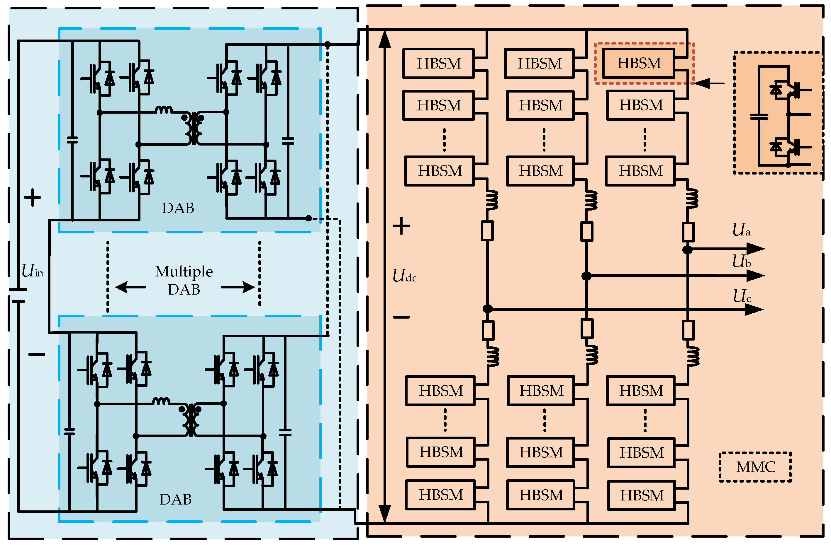
Figure 1 shows the DAB and MMC topologies. HBSM stands for half bridge submodule, and Udc is the MMC’s DC input voltage. Ua, Ub, and Uc are the AC voltages of phases A, B, and C, respectively, which are output by the MMC.
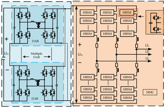
Figure 1.
The detailed topology of the MMC and DAB.
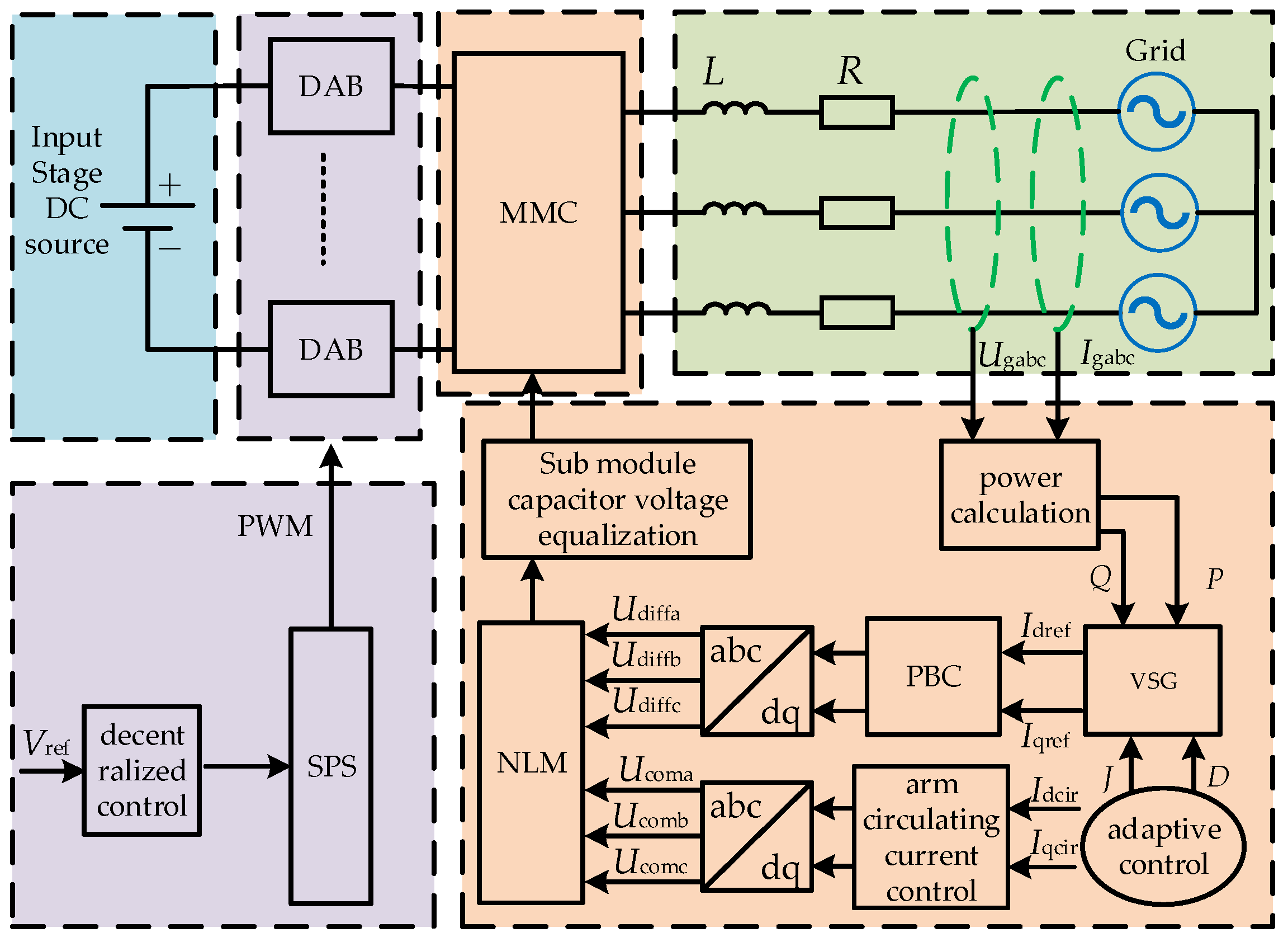
Figure 2 shows the main circuit topology and control of the MMC-HVDC grid-connected power control system. L and R are the equivalent inductance and resistance on the power grid cable, respectively.
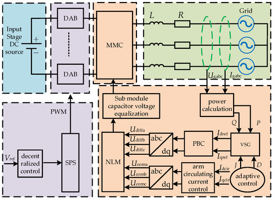
Figure 2.
MMC-HVDC system topology.
The MMC-HVDC system in this paper consists of three parts: the input stage, the isolation stage, and the output stage. The input stage is the high-voltage DC voltage output from the previous grid voltage system, which is represented by a DC source in this paper. The isolation stage is composed of multiple cascaded Dual Active Bridge (DAB) modules with Input Series Output Parallel (ISOP) [24], which provide stabilized voltage for the output stage. The output stage consists of the MMC, which acts as an inverter, converting high-voltage DC power into high-voltage AC power and ultimately integrating the energy from the input stage into the power grid.
3. MMC-HVDC Output Stage Control Strategy
3.1. MMC Mathematical Model
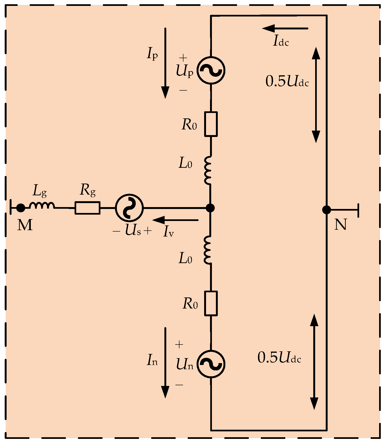
To simplify the analysis, this section takes phase A of the MMC for specific analysis. Figure 3 shows the A-phase topology of the output stage inverter of the MMC.
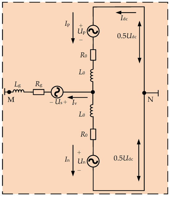
Figure 3.
Simplified diagram of phase A of the MMC.
In Figure 3, Udc is the DC-side voltage; Up is the voltage of the upper bridge arm HBSM; Un is the voltage of the lower bridge arm HBSM; L0 is the inductance of the bridge arm; R0 is the resistance of the bridge arm; Us is the grid-side voltage; Lg is the grid-side inductance; Rg is the resistance on the grid side; Ip is the upper bridge arm current; In is the lower bridge arm current; Iv is the grid-side current; and UNM is the potential difference between point N and point M. The value of UNM is generally taken as 0.
By applying Kirchhoff’s current voltage law to Figure 3, the equations for the upper and lower bridge arms can be obtained as follows:
Add the equations of the upper and lower bridge arms and then perform a dq-axis transformation to obtain the following:
where Ivd and Ivq are the bridge arm currents of the dq axis, respectively; Usd and Usq are the grid-side voltages of the dq axis, respectively; Udiffd and Udiffq are the differential mode voltages of the dq axis, respectively; ωa is the grid fundamental angular frequency; s is a differential operator; L = L0/2 + Lg; and R = R0/2 + Rg.
3.2. MMC Current Inner Loop PBC Control
Conventional PI control is sensitive to system parameter variations and external perturbations and requires precise parameter tuning to maintain performance. In the presence of uncertainties or perturbations in the system, PI control may cause performance degradation or even instability. In contrast, PBC control can naturally handle system uncertainties and external perturbations through energy shaping and damping injection. Even if the system parameters change, the control performance maintains stability provided the passivity condition is still satisfied.
Rewriting (2) into the Euler–Lagrange (EL) model form is calculated as follows:
where U is the input vector; x is the state variable; J is the interconnection matrix (antisymmetric); R is a semi-positive definite dissipative matrix; and M is a positive definite energy storage matrix. The expression of each matrix is as follows:
The MMC system and energy function can be expressed as follows:
where x is the state variable; u is the input variable; y is the output variable; and V is the energy function.
The derivative of the energy function of the MMC can be derived as follows:
According to (5), it can be concluded that the MMC satisfies passivity and can use passive-related control strategies.
The error EL model of the MMC is as follows:
where x* is the expected stable equilibrium point; xe is the state error; Ue is the output error; and Ve is the error energy function of the MMC. The expression of each matrix is as follows:
Derive the error energy function in (6) to obtain the following [24]:
To enable the system to quickly converge to the desired point, that is, to rapidly reduce the error energy function to zero, damping acceleration energy dissipation can be introduced. The error EL model of the MMC injected with damping is as follows:
where Rtxe = (R + Ra)xe, .
To eliminate steady-state errors and achieve decoupling, set (8) to 0 and substitute it into the derivative of the energy function to obtain the following:
At this point, (9) achieves decoupling and is less than 0, indicating that the selected U can rapidly converge the energy error function.
Substituting (8) into (5) yields (10):
Figure 4 illustrates the passive controller for the MMC, which was derived from Equation (10).
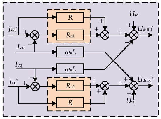
Figure 4.
MMC inner loop passive control.
Substitute (10) into (2) to obtain the relationship between the passive control current of the MMC inner loop and its reference value can be obtained as follows:
The relationship between the traditional MMC inner loop PI control current and its reference value can be expressed as follows:
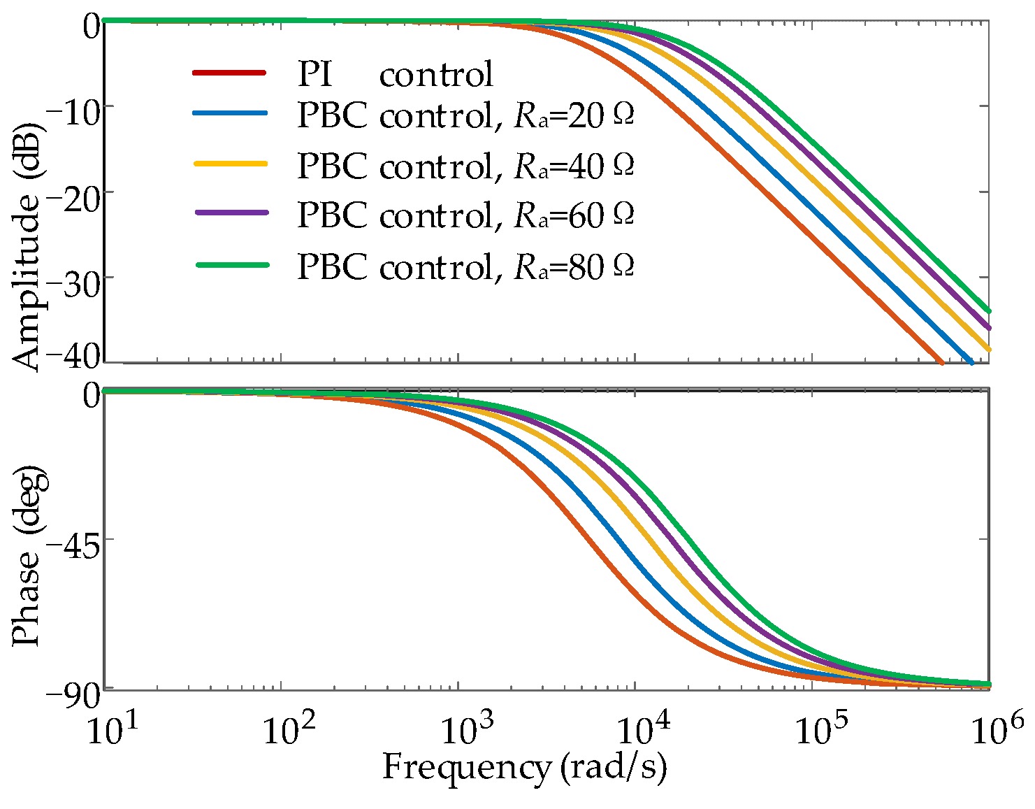
Figure 5 shows the amplitude–frequency and phase–frequency characteristic curves of (11) and (12).
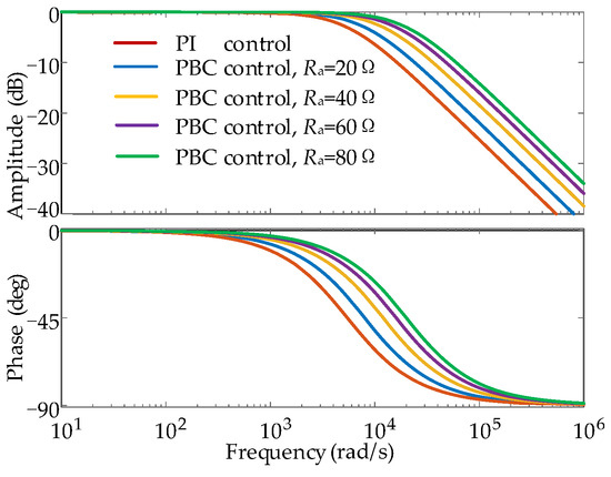
Figure 5.
Amplitude–frequency and phase–frequency diagram of the MMC inner loop current.
Based on Figure 5, PBC control has a higher cut-off frequency compared to traditional PI control, and the bandwidth of the current loop is also larger. The PBC control system’s signal-tracking ability is stronger, and its response speed is faster. Furthermore, as the injection resistance increases, the system’s cut-off frequency increases, but the system’s anti-interference ability will weaken.
3.3. MMC Power Outer Loop VSG Control
3.3.1. MMC-VSG Control
Traditional PI control is mainly applicable to linear systems, with limited performance when facing complex nonlinear systems. In contrast, VSG control can better adapt to the complex operating environment of the nonlinear system by simulating the dynamic characteristics of synchronous generators and improving the stability, reliability, and power quality of the system, especially in a weak grid environment, which has significant advantages.
The MMC-VSG control needs to satisfy the rotor motion equation of the synchronous generator:
where Pm is the mechanical power; Pe is the electromagnetic power; ω is the mechanical angular velocity of the synchronous generator; and ω0 is the reference grid angular velocity.
A governor with active frequency droop characteristics is introduced in VSG control to simulate the frequency regulation characteristics of synchronous generators:
where Pref is the reference active power; Kp is the active power frequency droop coefficient.
Substituting (14) into (13), the following can be obtained:
The virtual voltage controlled by a VSG consists of three parts. The first part is the no-load electromotive force En of the VSG; the second part is the VSG reactive power regulation section ΔEQ; and the third part is the VSG terminal voltage regulation section ΔEV. By simultaneously introducing an integral excitation regulator, we can obtain the expression for reactive voltage control.
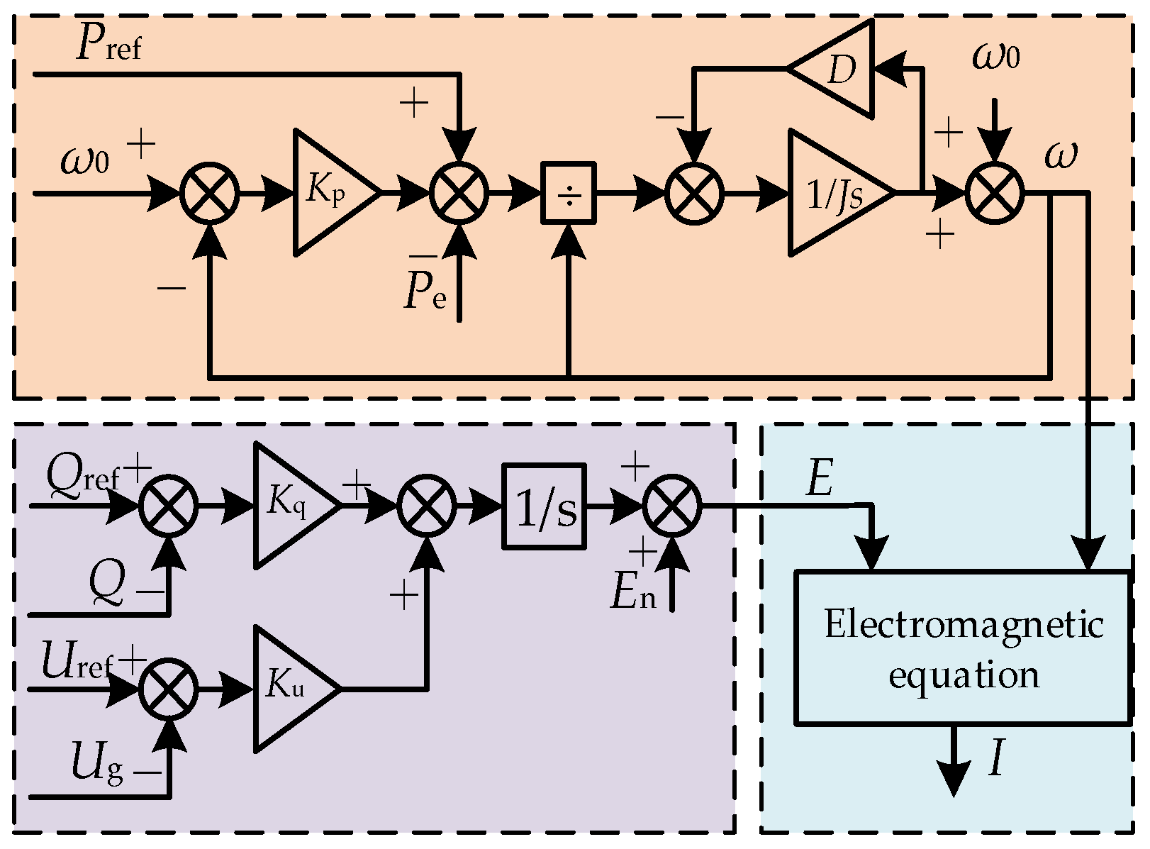
As shown in Figure 6, the MMC-VSG control diagram can be obtained from (15) and (16).
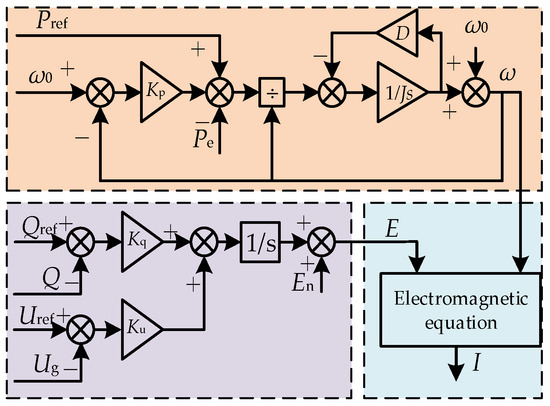
Figure 6.
MMC-VSG control.
3.3.2. The Influence of J and D on the Dynamic Response of MMC-VSG Control
The formula for the active power output of the MMC-VSG can be expressed as follows:
where K is the output power coefficient; X is the equivalent line reactance; U is the effective value of the grid voltage; E is the effective value of the VSG terminal voltage; and θ is the phase angle difference between E and U. When θ is very small, sinθ is approximately equal to θ.
If the coupling between active and reactive power circuits is not considered, the power frequency small signal model controlled by a VSG is as follows:
According to (18), the natural angular frequency, damping ratio, and their open-loop transfer function can be determined as follows:
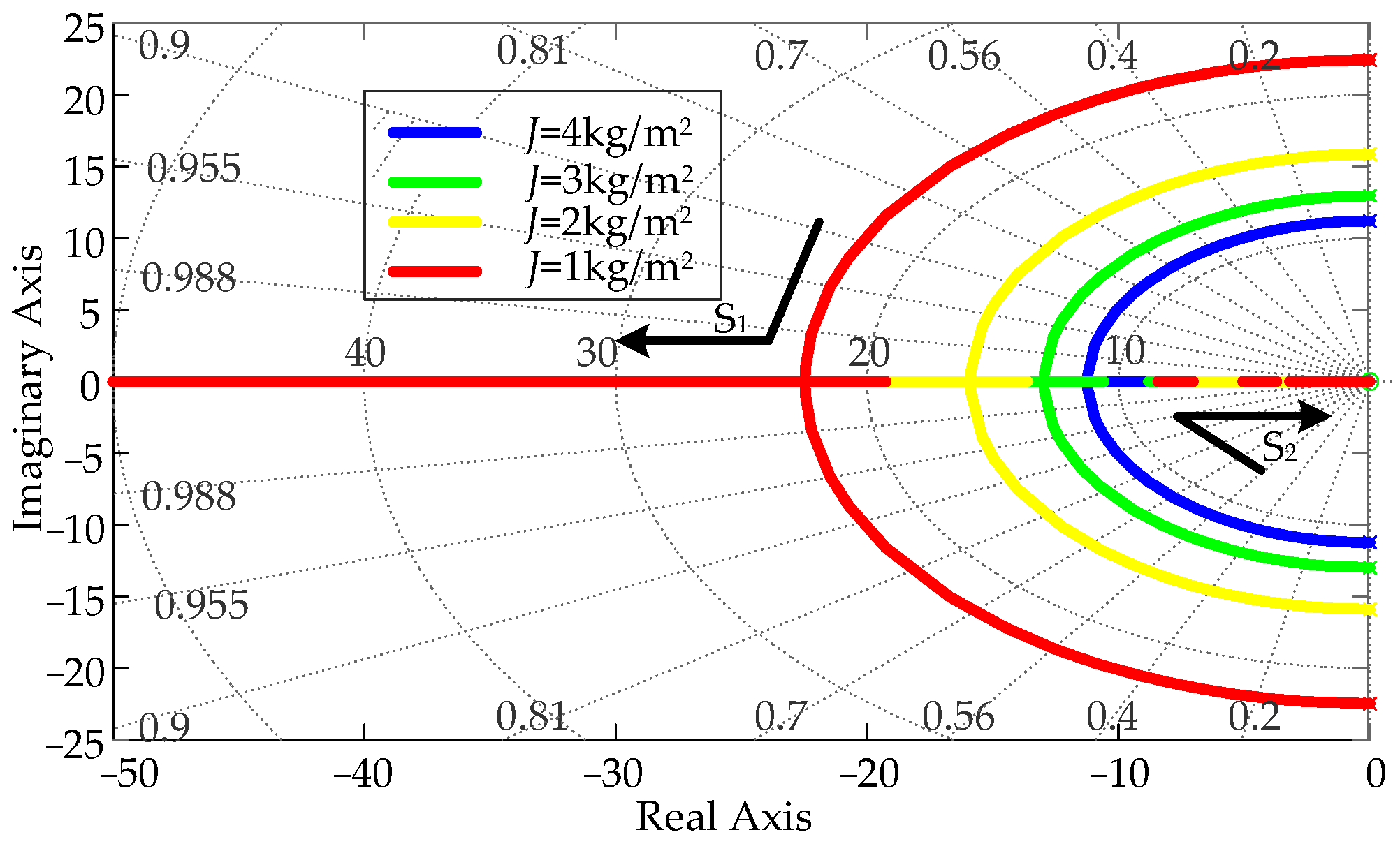
As shown in Figure 7, the root trajectories of changes in J and D parameters can be plotted using (19).
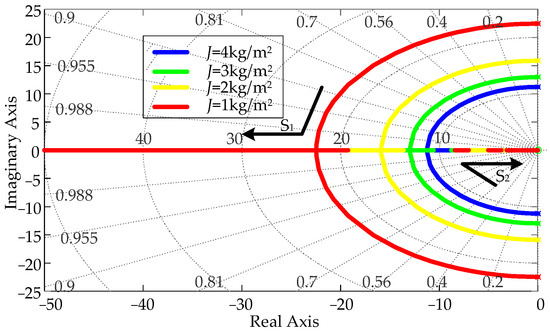
Figure 7.
Root locus diagram of changes in J and D.
As shown in Figure 7, when the J value is constant, the pole varies with the damping coefficient D. As D increases, the damping ratio increases, and the pole gradually approaches the negative real axis from the negative imaginary axis. The system will transition from underdamping to overdamping, improving system stability but slowing down response time. On the contrary, when the damping coefficient D is constant, the pole changes with the moment of inertia J. As J increases, the product of the system damping ratio and natural frequency decreases, and the system’s stability time becomes longer. Therefore, the values of J and D are crucial for the MMC-VSG control system.
3.3.3. VSG Parameter Adaptive Control
In weak grid environments, the MMC-HVDC system is prone to power and frequency oscillations. This oscillation is usually a damped oscillation. J affects the system’s response speed, while D affects the amplitude variation in the system. Let the difference between the angular velocity of the VSG and the reference angular velocity be ∆ω, and the rate of change in angular velocity be dω/dt.
For the synchronous generator simulated by the VSG, the system undergoes several dynamic phases after being perturbed. In the initial disturbance stage, after the system is perturbed, the input mechanical power to the generator is larger than the output electromagnetic power, and the rotor obtains the accelerating torque, ∆ω > 0, dω/dt > 0. In order to ensure the stability of the system’s angular velocity, the change in angular frequency must be reduced, and at this time, J and D should be increased.
In the inertial response phase, the output electromagnetic power is gradually larger than the input mechanical power. As the power angle increases and other influencing factors come into play, the rotor is subjected to deceleration torque, ∆ω > 0, dω/dt < 0. To reach the grid angular velocity as soon as possible, J and D should be reduced appropriately.
In the damped oscillation phase, the system is in the process of restoring stability, and the angular velocity fluctuates around the rated value with small fluctuations due to the interaction of the mechanical and electromagnetic transient processes, ∆ω < 0 and dω/dt < 0. In order to reduce the slew rate and the angular velocity overshoot, the inertia J and D should be increased appropriately.
In the phase of convergence to stabilization, the oscillations have decayed, and the system gradually overcomes the effects of the perturbations, with Δω < 0 and dω/dt > 0. In order for the system to reach its nominal angular velocity quickly, it is necessary to reduce the inertia J and increase D.
Based on the above analysis, corresponding adaptive control strategies can be designed as follows:
where J0 and D0 are the set values of the moment of inertia and damping coefficient for VSG control, respectively; Kj and Kd are adjustment coefficients for J and D; and Ti and Td are the thresholds.
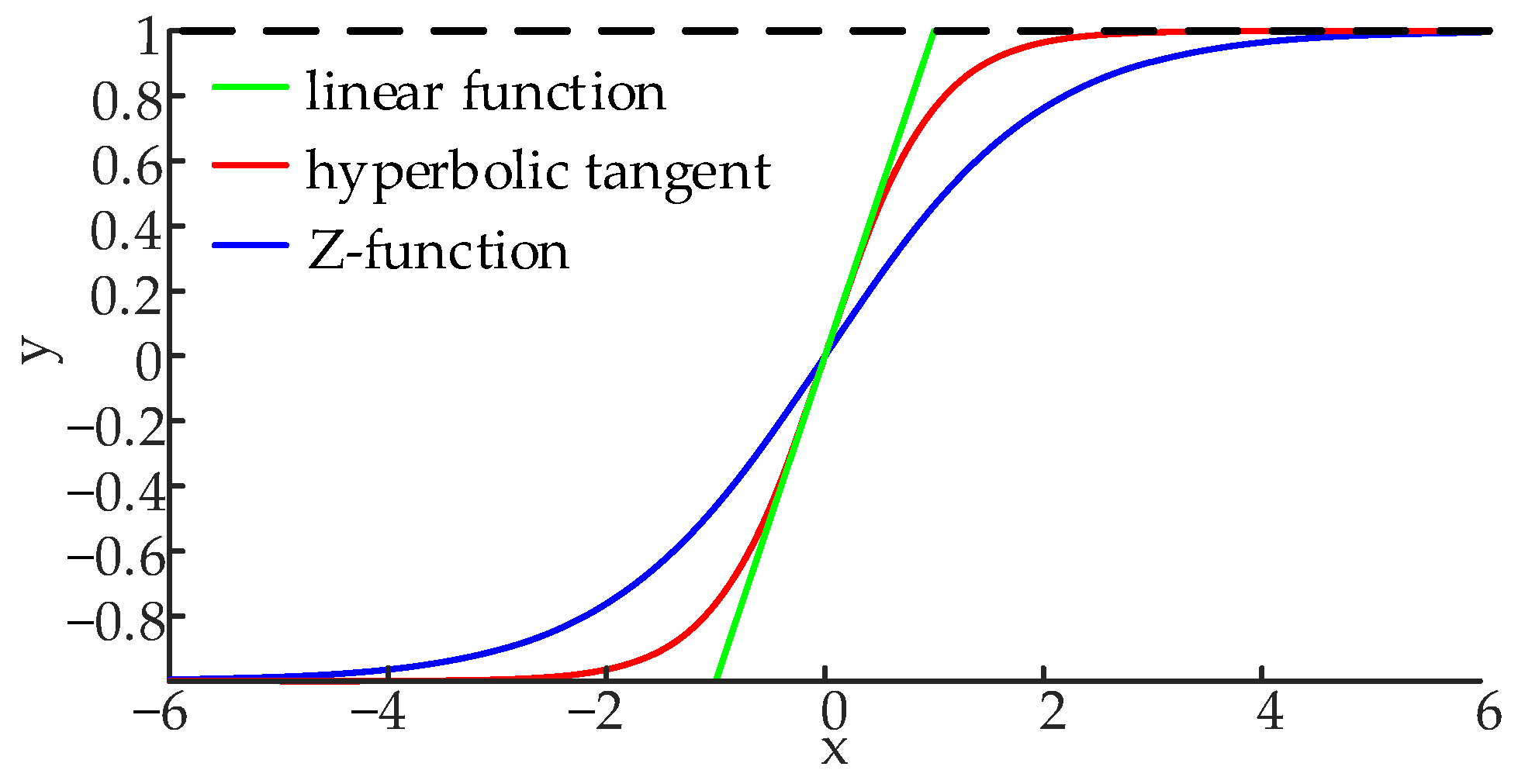
Although the current approach can achieve adaptive J and D parameters, it cannot limit amplitude due to its dependence on linear functions. This limitation can lead to excessive fluctuations in the J parameter, which ultimately degrades the system’s dynamic performance. To address these issues, some researchers have proposed using hyperbolic tangent functions. This method introduces an amplitude-limiting function into the control mode and reduces the rate of change in the J parameter, effectively enhancing the system’s dynamic performance. The control method is as follows:
On this basis, this paper proposes the introduction of a sigmoid function to further improve the dynamic performance of the system, and its control method is as follows:
Figure 8 shows the graphs of the hyperbolic tangent function, Z-function, and linear function. Compared with the other two functions, the sigmoid function has a smoother rate of change and also possesses an amplitude-limiting function. This can prevent parameter changes from being too large or too fast, thereby improving the system’s dynamic performance. Among them, the Z function is defined as twice the sigmoid (x), minus 1.
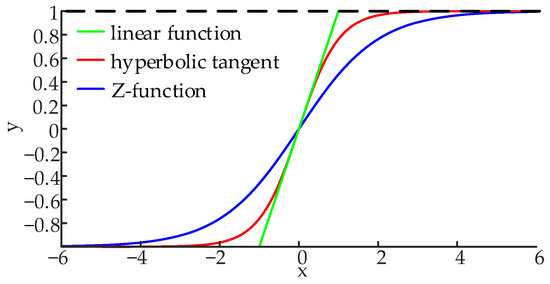
Figure 8.
Power angle and angular power oscillation curves.
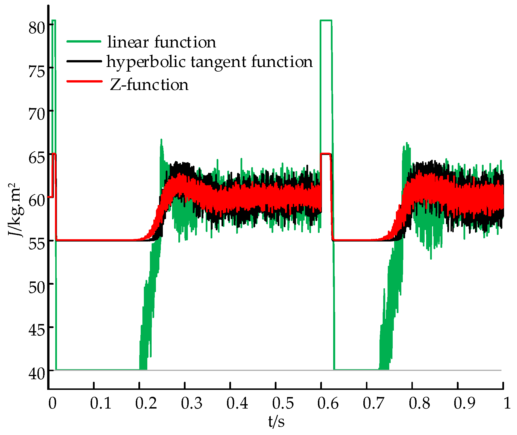
Figure 9 shows the variation in the J value when different control methods are used under power changes. The initial active power of 6 MW is set to become 8 MW after 0.6 s. The value of J0 is 60 kg·m2, the value of D0 is 2553 N·m·s/rad, and the value of the adaptive adjustment factor Kj is 5. Among them, the linear function control method adds an amplitude limiter so that its J value varies between 40 to 80, while the other two function control methods do not have an amplitude limiter.
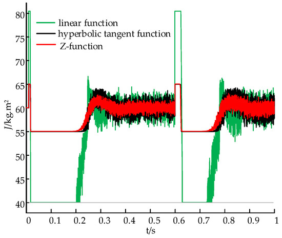
Figure 9.
Variation diagram of parameter J.
As shown in Figure 9, during the startup phase, the value of dω/dt is much larger than the threshold value of the adaptive control. The adaptive control with linear function can only rely on the amplitude limiter, so the value of J varies greatly, while the adaptive control with the Z-function and hyperbolic tangent function can limit the amplitude fluctuation of J to Kj. In addition, the Z-function has a smoother curve than the hyperbolic tangent function, which leads to a smoother change in the J value using the Z-function, which results in a smaller amplitude of J value fluctuation and better dynamic performance. When the system power changes from 6 MW to 8 MW, the dω/dt values change again, repeating the previous adaptive regulation of the J value. Due to the limited range of values of Δω, the variation in D will not be explored in detail in this paper.
4. MMC-HVDC Isolation Stage Control Strategy
It is difficult for a single DAB to withstand the high voltage in the MMC-HVDC system. In order to reduce the withstand voltage of a single DAB, the DAB structure in this paper is of ISOP type. In the ISOP configuration, the total input voltage is distributed across multiple DAB modules in series, thereby reducing the withstand voltage requirement for each individual DAB. When multiple DAB circuits are cascaded, voltage imbalance is likely to occur because the parameters of each module may not be consistent. Voltage imbalance causes an increase in power loss, which reduces the efficiency of the whole system, and long-term voltage imbalance operation leads to a decrease in system stability.
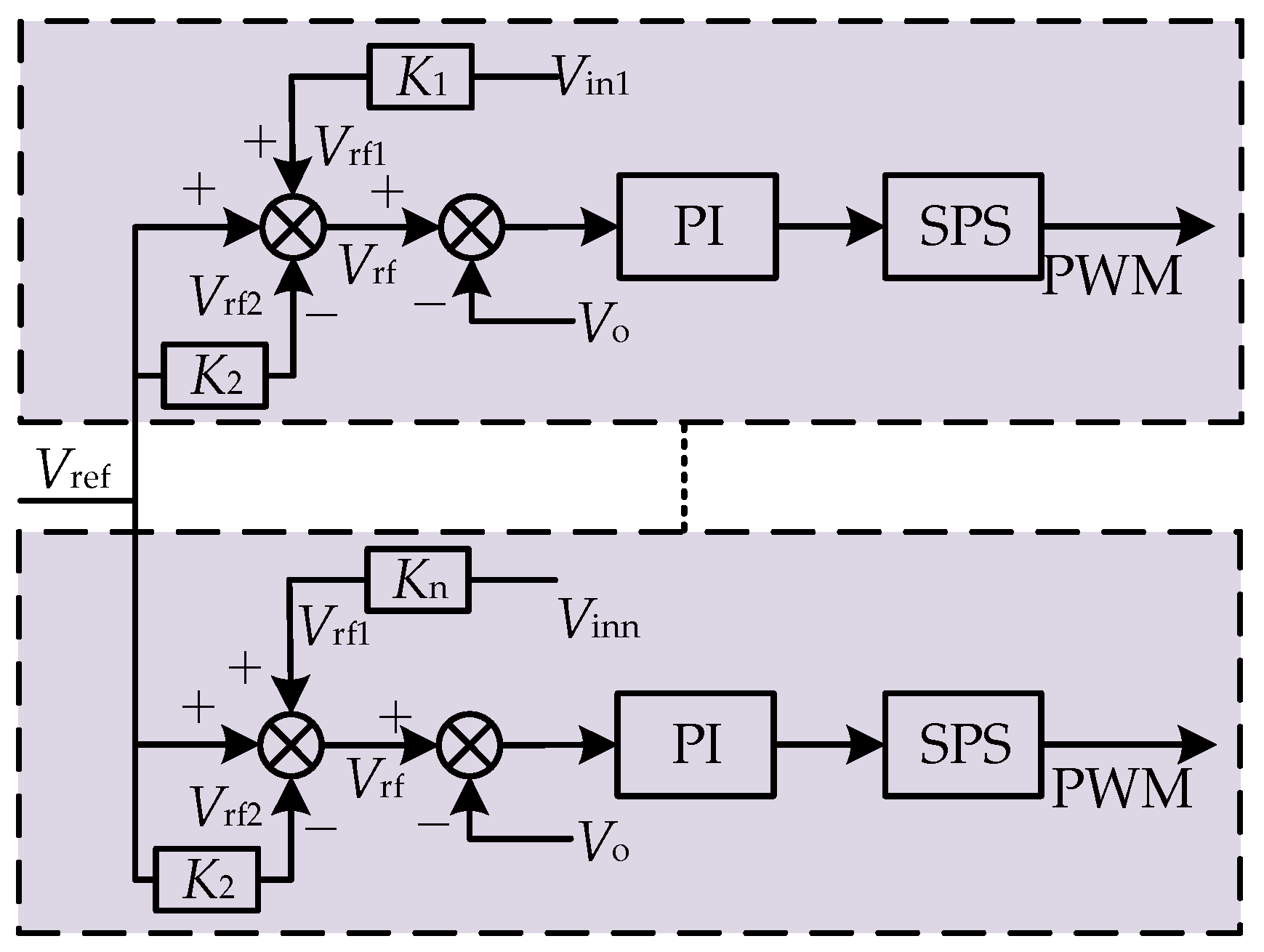
To address this problem, this paper uses a decentralized approach to control the voltage balance at the input port of an ISOP-type DAB. The control principle is as follows. First, the average input voltage of the DAB converter, denoted as Vin, is introduced. Then, a proportional function is applied to Vin to obtain a corrected value Vrf1 based on the given reference output voltage Vref of the DAB converter. At this time, there is a slight difference between Vref and Vrf1. To reduce this error, a correction coefficient is introduced. The correction coefficient is multiplied by Vref to obtain a further corrected value Vrf2, which aims to minimize the deviation of Vrf from Vref. The Vrf is then compared with the actual value of the output voltage Vo. The resulting error signal is fed into a PI controller, which generates a phase shift modulation value. This phase shift modulation value is then used to obtain the PWM wave through a Single-Phase Shift (SPS) modulation process, and finally, the output voltage control is achieved. The control topology is shown in Figure 10.
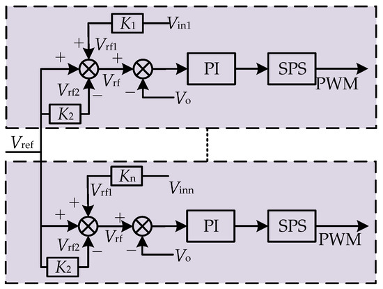
Figure 10.
DAB voltage control.
To verify the effectiveness of the ISOP-DAB input voltage equalization control strategy, the inductance values of the four DAB converters are set to 12 µH, 10 µH, 8 µH, and 6 µH, respectively, and the input voltage is set to 4000 V. Figure 11 shows the voltage waveforms of the DAB inputs with different inductance parameters.
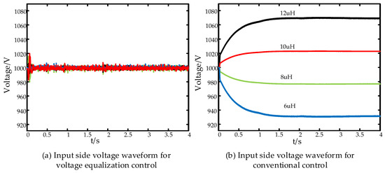
Figure 11.
DAB input voltage: (a) input-ide voltage waveform for voltage equalization control; (b) input-side voltage waveform with conventional control.
Based on Figure 11, it can be seen that when voltage equalization control is not used, the input-side voltage is not uniform due to the different parameters of the submodule DAB, which seriously threatens the stability and transmission efficiency of the system. In contrast, after using the voltage equalization control, the submodule input voltage is stabilized at about 1000 V after control regulation. Thus, the effectiveness of the ISOP-type DAB input voltage equalization control is verified.
5. Simulation Results and Analysis
To verify the effectiveness of the VSG-PBC parameter adaptive control method proposed in this paper, a grid-connected simulation model was built in MATLAB/Simulink based on the MMC-HVDC system topology shown in Figure 2. The MMC-HVDC system is set up to simulate and compare the adaptive VSG-PBC control with the non-adaptive VSG-PBC control and the traditional VSG control under given power, grid voltage amplitude, and load changes on the grid side. The main parameters of the system are shown in Table 1.

Table 1.
MMC-HVDC system simulation parameters.
5.1. Given Output Power Variations
The simulation system parameters are set according to the values in Table 1, and the simulation time is 2 s. At 0~1 s, the given power is 6 MW; at 1~2 s, the given power suddenly changes to 8.5 MW.
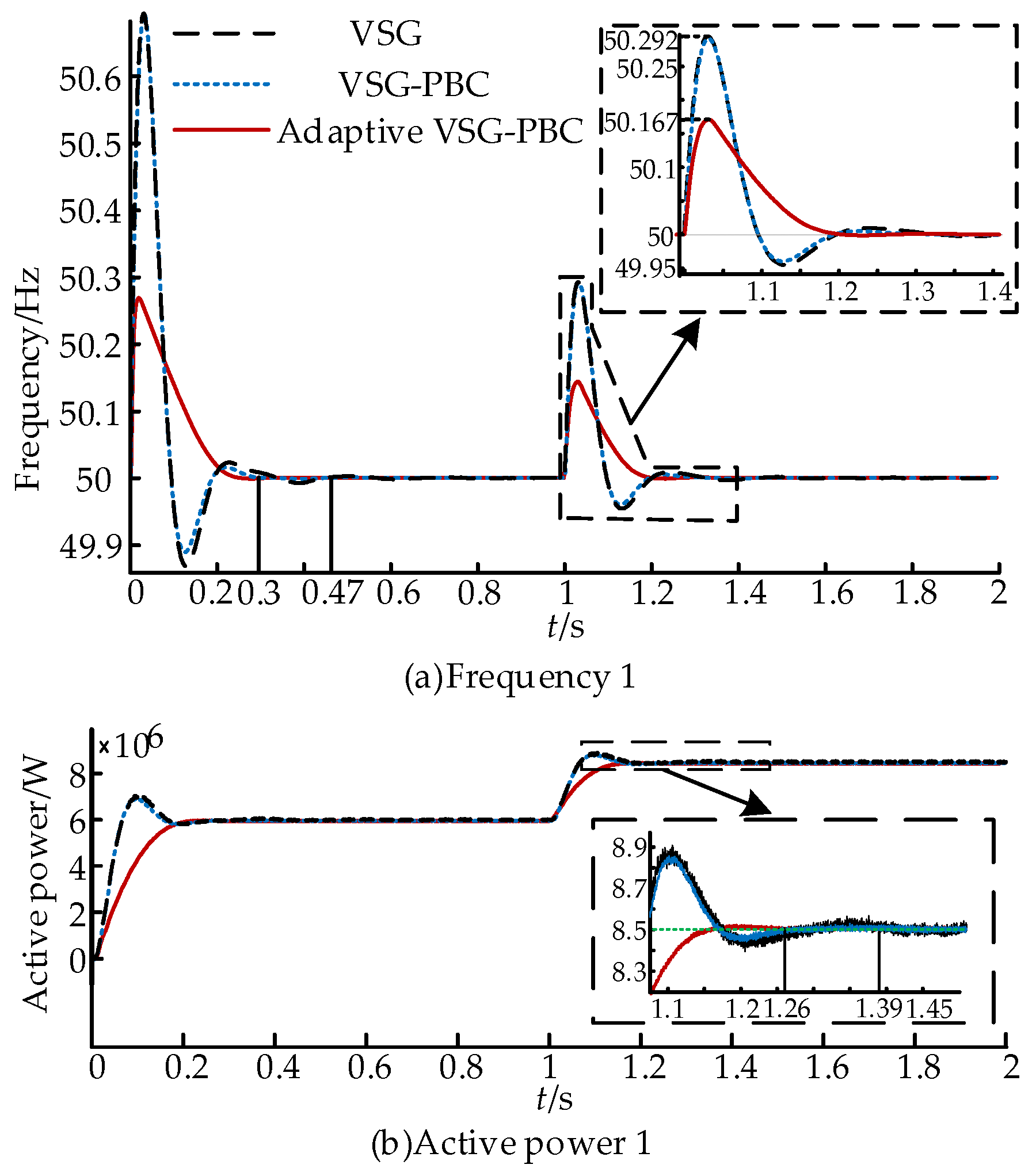
Based on Figure 12, it is evident that the system frequency stabilizes at 0.3 s when utilizing PBC during startup. In contrast, traditional VSG control takes 0.47 s to reach stability. At 1 s, the output active power of the MMC system abruptly increases from 6 MW to 8.5 MW. Under PBC control, stability is achieved at 1.26 s, whereas traditional VSG control requires 1.39 s to stabilize. The maximum frequency peak is 50.167 Hz with adaptive VSG-PBC control compared to 50.292 Hz without adaptive control. In terms of power performance, the adaptive VSG-PBC control has almost no power overshoot due to adaptive change in the parameters of J and D compared to the maximum power overshoot of 8.87 MW with conventional VSG control.
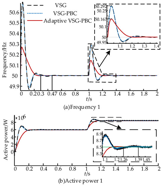
Figure 12.
Power frequency response under power variations: (a) frequency 1; (b) active power 1.
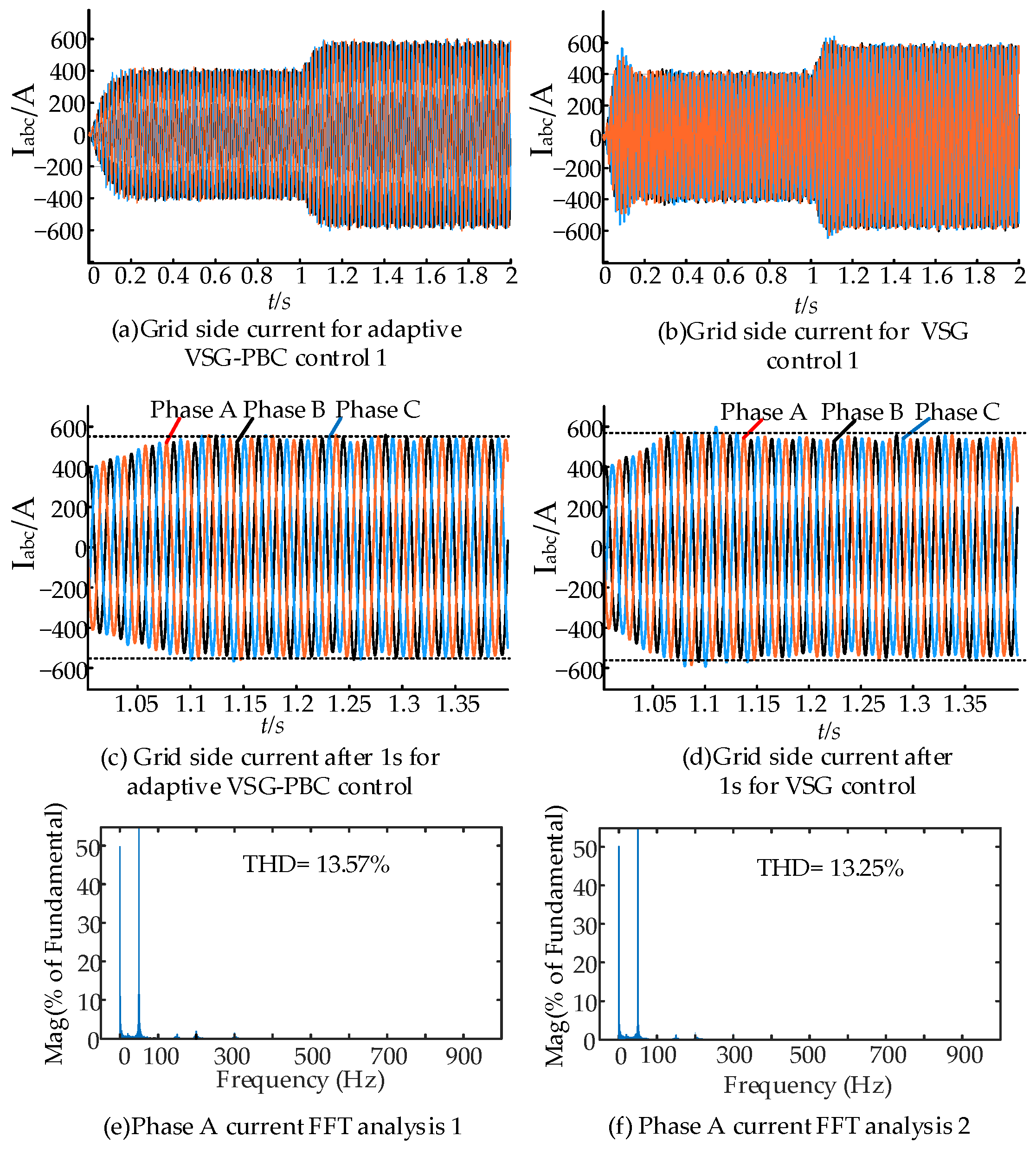
As shown in Figure 13d, the peak value of the grid-side current reaches 621 A when the conventional VSG control is used and the power changes, while the peak value of the grid-side current reaches 586 A when the adaptive VSG-PBC is used, as shown in Figure 13c. In addition, based on Figure 13d, it can be observed that the conventional VSG control current inner loop is under PI control. Due to the PI value being fixed, when there is a sudden power change, the value cannot be automatically coordinated with the changing system, resulting in a degradation of the current performance. In Figure 13c, it can be seen that the adaptive VSG-PBC control introduces PBC control under the working condition of a given power variation, and the control performance of the current remains stable as long as the passive condition is still satisfied. Figure 13e shows the FFT analysis of the A-phase of the conventional VSG power control. Figure 13f shows the FFT analysis of the A-phase of the adaptive VSG-PBC power control. The Total Harmonic Distortion (THD) value of the A-phase is larger in the full time period because of the sudden change in the given power, but still, it can be observed that the current THD value is smaller and the system is stable under the condition of a sudden change in the given power with the adaptive VSG-PBC power control.
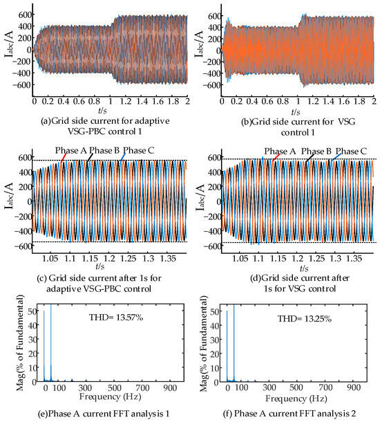
Figure 13.
Grid-side current under power variations: (a) grid-side current for adaptive VSG-PBC control 1; (b) grid-side current for VSG control 1; (c) grid-side current after 1 s for adaptive VSG-PBC control; (d) grid-side current after 1 s for VSG control; (e) phase A current FFT analysis 1; and (f) phase A current FFT analysis 2.
5.2. Operating Conditions of Variations in Voltage Amplitude on the Grid Side
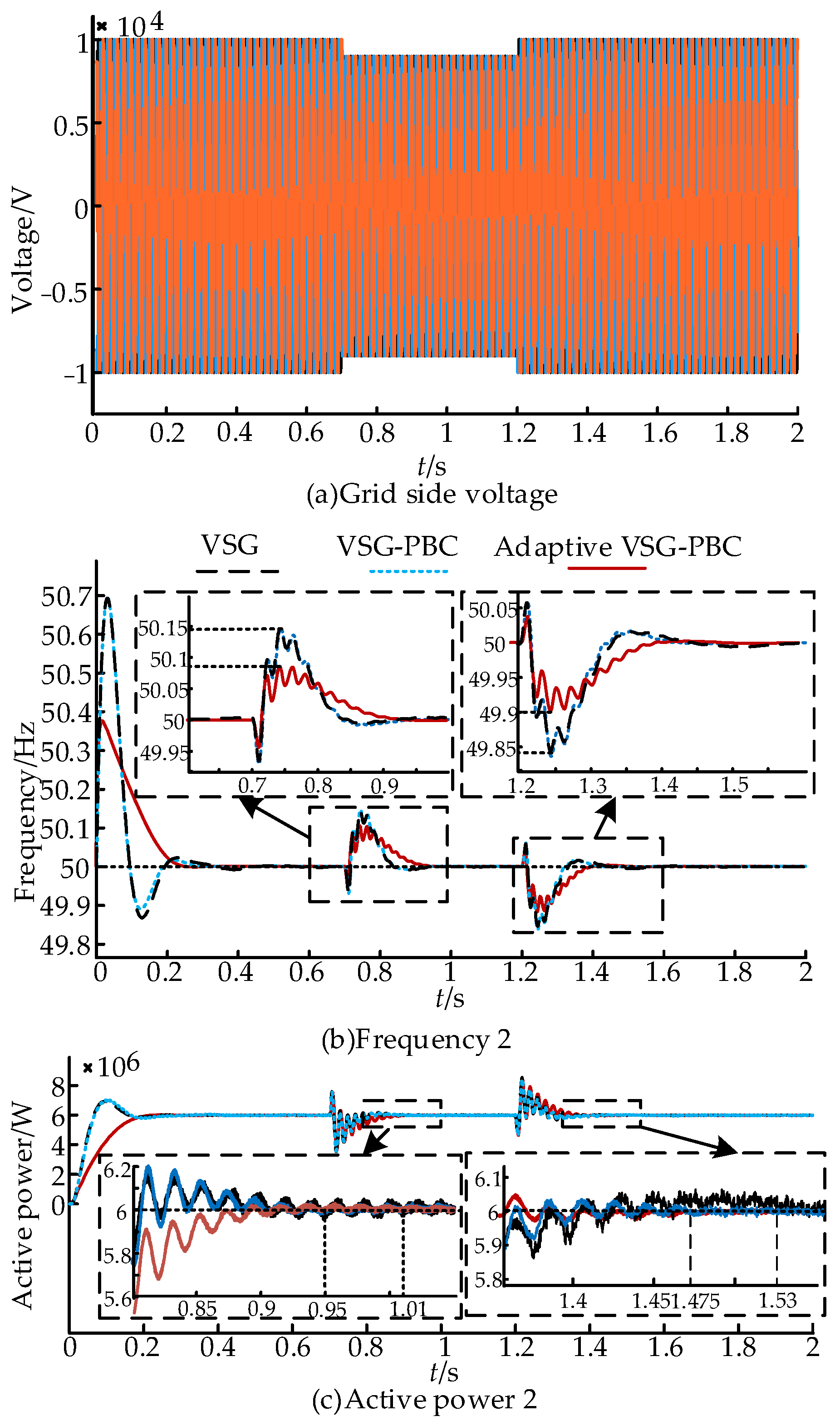
The simulation system parameters are set according to the values in Table 1, ensuring that the given active power is 6 MW and the grid amplitude decreases by 10% during the period from 0.7 s to 1.2 s and returns to normal after 1.2 s.
Based on Figure 14, it is clear that as the voltage amplitude on the grid side decreases, the VSG control effectively tracks the grid voltage due to its voltage regulation capability. When there is a sudden drop in the voltage amplitude of the power grid, the control using PBC stabilizes at 0.95 s, while traditional VSG control stabilizes at 1.01 s. When the voltage amplitude returns to normal, the PBC control achieves stability at 1.475 s, compared to 1.53 s for the traditional VSG control.
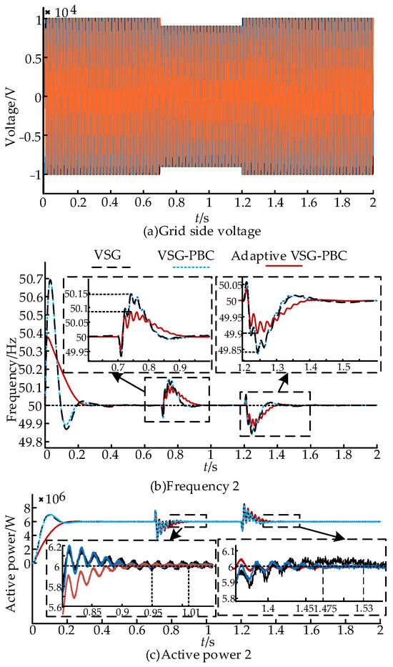
Figure 14.
Power frequency response under power grid voltage amplitude variations: (a) grid-side voltage; (b) frequency 2; and (c) active power 2.
During the sudden drop in voltage amplitude, the maximum frequency peak value with the adaptive VSG-PBC control is 50.1 Hz, while the peak value without adaptive control is 50.15 Hz. When the voltage amplitude resumes normal levels, the maximum frequency offset with adaptive VSG-PBC control reaches 49.9 Hz, whereas the offset without adaptive control is 49.85 Hz. Adaptive VSG-PBC control provides a smoother and more stable power output compared to the other two control methods.
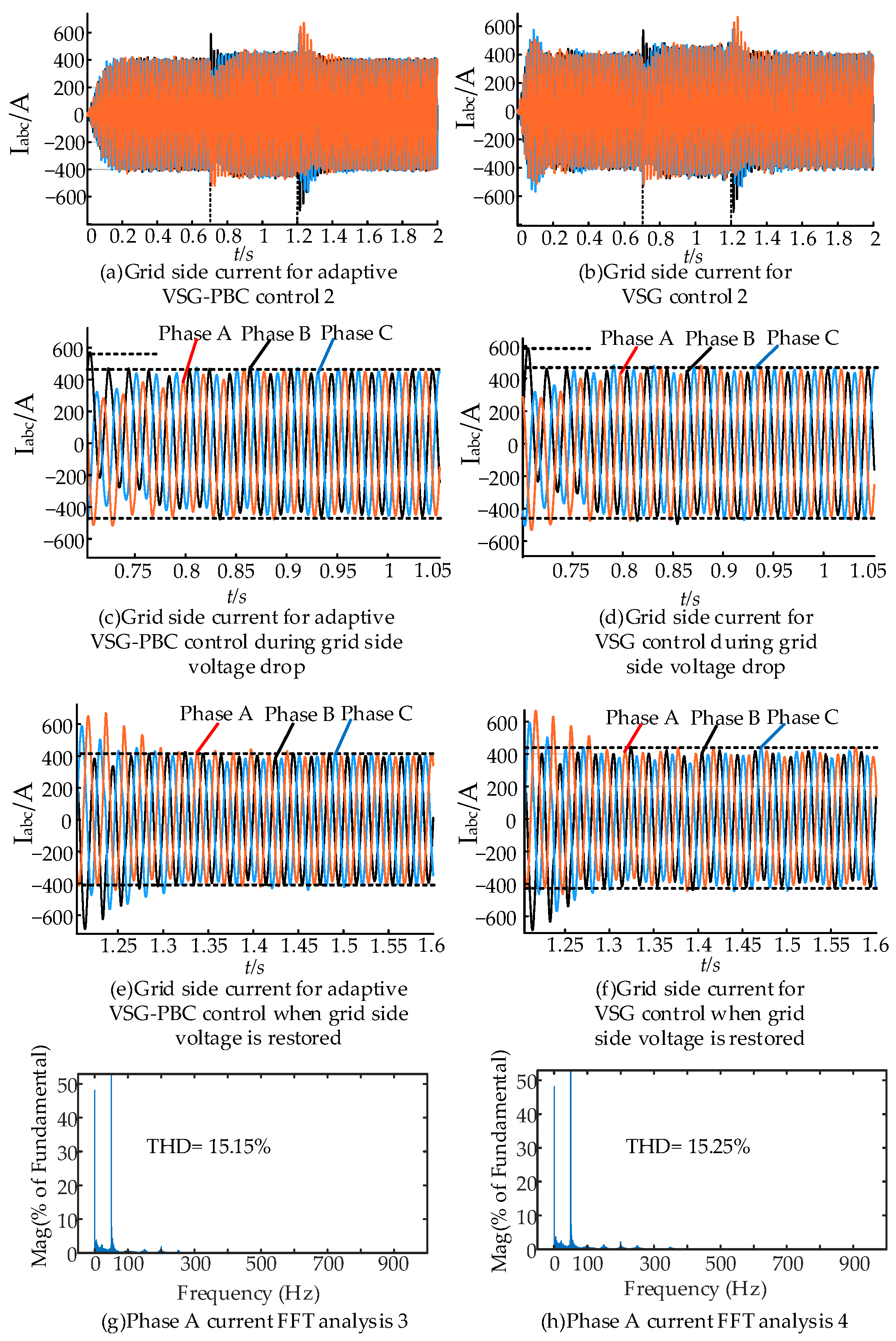
As shown in Figure 15d, when the grid-side voltage changes, the peak grid-side current reaches 589 A with the conventional VSG control, while the peak grid-side current reaches 576 A with the adaptive VSG-PBC control, as shown in Figure 15c. In addition, based on Figure 15d,f, it can be concluded that the traditional VSG control current inner loop is a PI control, and when the grid-side voltage changes abruptly, the current performance is degraded due to the fixed value of its PI, which cannot be automatically coordinated with the changing system. In Figure 15c,e, it can be seen that the adaptive VSG-PBC control introduces PBC control under the working condition of grid-side voltage variation, and the control performance of the current remains stable as long as the passive condition is still satisfied. Figure 15g shows the FFT analysis of conventional VSG power control of the A-phase current. Figure 15h shows the FFT analysis of the adaptive VSG-PBC power control of the A-phase current. The THD value of the A-phase current is larger throughout the time period due to the variation in the grid-side voltage magnitude, but it can be seen that the THD value of the current is smaller and the system is more stable for the adaptive VSG-PBC power control.
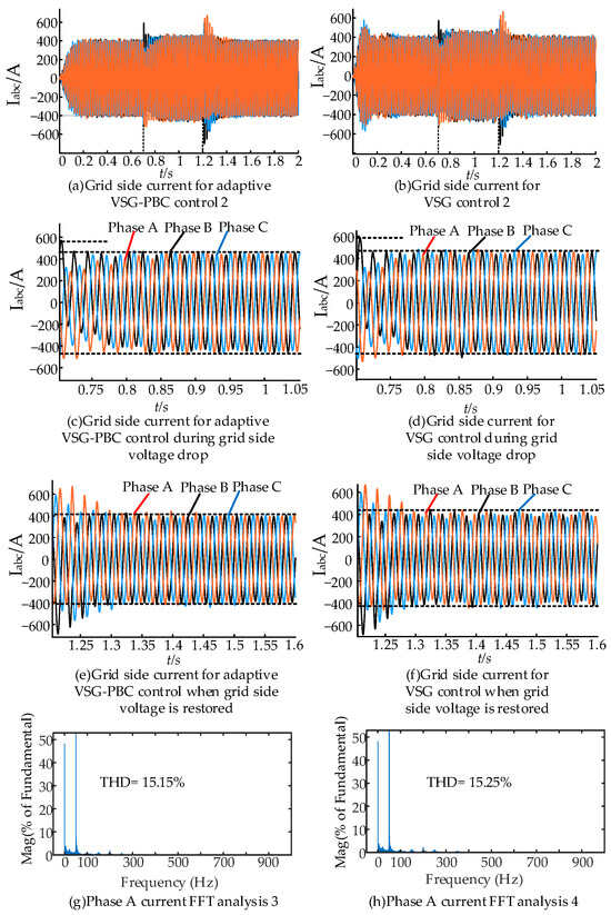
Figure 15.
Grid-side current response under power grid voltage amplitude variations: (a) Grid-side current for adaptive VSG-PBC control 2; (b) grid-side current for VSG control 2; (c) grid-side current for adaptive VSG-PBC control during grid-side voltage drop; (d) grid-side current for VSG control during grid-side voltage drop; (e) grid-side current for adaptive VSG-PBC control when grid-side voltage is restored; (f) grid-side current for VSG control when grid-side voltage is restored; (g) phase A current FFT analysis 3; and (h) phase A current FFT analysis 4.
5.3. Grid-Side Load Mutation Condition
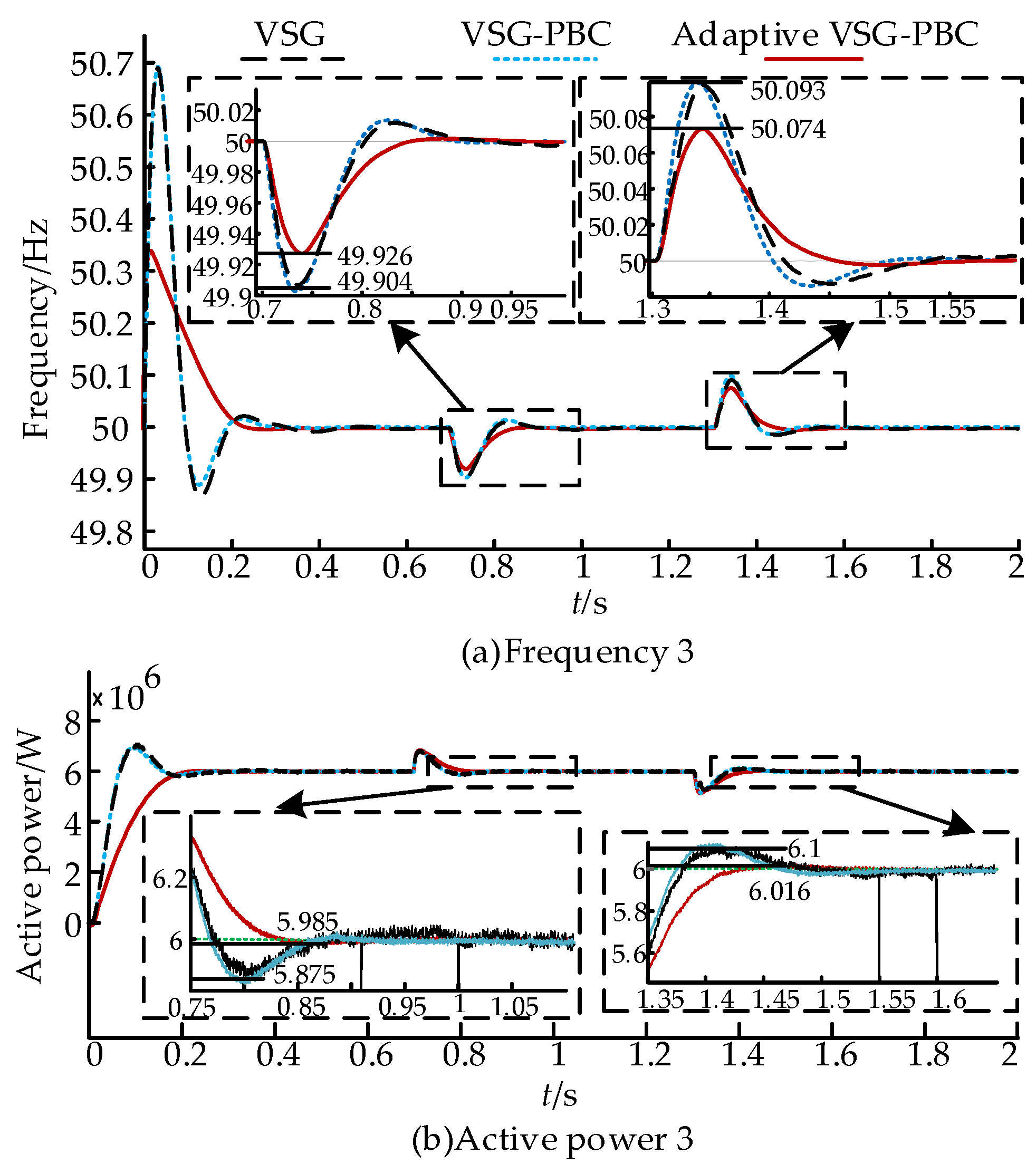
The simulation system parameters are set according to the values in Table 1, ensuring that the given active power is 6 MW. When the time is 0.7 s, 1 MW of the grid-side load is applied, and the added grid-side load is cut off at 1.3 s.
Figure 16 shows that when the load is applied at 0.7 s, the PBC reaches stability by 0.91 s, while the traditional VSG control takes 1.1 s to stabilize. When the load is removed at 1.3 s, the PBC control achieves stability in 1.55 s, whereas the traditional VSG control takes 1.61 s to reach stability.
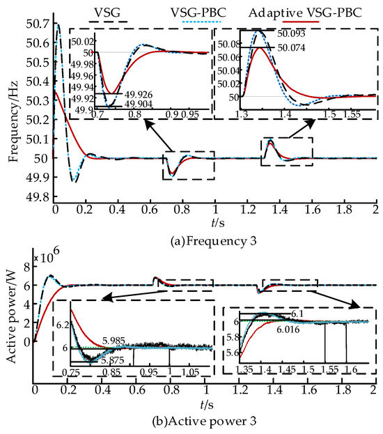
Figure 16.
Power frequency response under grid-side load changes: (a) frequency 3; (b) active power 3.
During the load application, the maximum frequency offset with adaptive VSG-PBC control is 49.926 Hz, while the maximum frequency offset without adaptive control reaches 49.904 Hz. During load shedding, the maximum frequency offset using adaptive VSG-PBC control is 50.074 Hz, compared to 50.093 Hz without adaptive control.
In terms of power, the peak values of using adaptive VSG-PBC control are almost the same as the other two controls. However, when the load approaches a steady state just after being put into operation, the maximum power offset using adaptive VSG-PBC control is 5.985 MW, while the maximum power offset without adaptive VSG control reaches 5.875 MW. When approaching a steady state just after load shedding, the maximum power offset using adaptive VSG-PBC control is 6.1 MW, while the maximum power offset without adaptive VSG control reaches 6.016 MW.
As shown in Figure 17f, when the grid-side load varies, the peak grid-side current reaches 440 A with the conventional VSG control, while the peak grid-side current reaches 421 A with the adaptive VSG-PBC control, as shown in Figure 17e. In addition, in Figure 17d,f, it can be seen that the traditional VSG control current inner loop is PI control, which leads to current performance degradation due to the fixed PI value that cannot be automatically coordinated with the changing system when the load on the grid side changes abruptly. In Figure 17c,e, it can be seen that the adaptive VSG-PBC control introduces PBC control under the working condition of grid-side load variation, and the control performance of the current remains stable as long as the passive condition is still satisfied. Figure 17g shows the FFT analysis of conventional VSG power control of the A-phase current. Figure 17h shows the FFT analysis of the adaptive VSG-PBC power control of the A-phase current. The THD value of the A-phase current is larger throughout the time period due to the variation in the load on the grid side, but it can be seen that the THD value of the current is smaller and the system is more stable for the adaptive VSG-PBC power control.
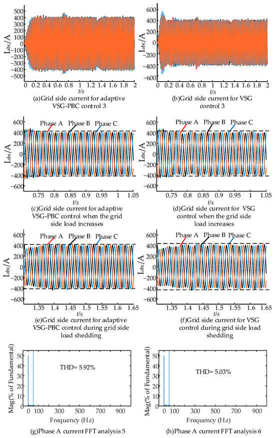
Figure 17.
Grid-side current under grid-side load changes: (a) grid-side current for adaptive VSG-PBC control 3; (b) grid-side current for VSG control 3; (c) grid-side current for adaptive VSG-PBC control when the grid-side load increases; (d) grid-side current for VSG control when the grid-side load increases; (e) grid-side current for adaptive VSG-PBC control during grid-side load shedding; (f) grid-side current for VSG control during grid-side load shedding; (g) phase A current FFT analysis 5; and (h) phase A current FFT analysis 6.
Overall, the adaptive VSG-PBC control reduces frequency and power amplitude oscillations and overshoots by adaptively adjusting the virtual inertia and virtual damping of the MMC-HVDC system under the operating conditions of power change, grid-side voltage amplitude change, and grid-side load change. In addition, it improves the response speed of the MMC-HVDC system through damping injection and energy shaping, optimizes the current tracking performance, and reduces the current distortion, thereby reducing the harmonic content, which in turn improves the dynamic performance and enhances the stability.
6. Conclusions
This paper proposes a grid-connected power control method for the MMC-HVDC system based on adaptive VSGs and PBC to address the problem of poor dynamic performance in traditional control of the MMC-HVDC system in weak grid environments. The following conclusions were drawn through simulation experiments:
- (1)
- The adaptive VSG-PBC control strategy, when compared to traditional VSG control methods, integrates PBC in the current inner loop. The control strategy is based on the passivity of the system and injects additional damping into the control system to enhance energy dissipation and accelerate system regulation. In addition, the PBC control improves the power quality of the grid-connected currents in the MMC-HVDC system by changing the cut-off frequency of the current inner-loop control system.
- (2)
- The adaptive VSG-PBC control strategy, when compared to traditional VSG control methods, incorporates adaptive VSG control in the power outer loop. The strategy includes a mechanism for virtual inertia compensation that employs a sigmoid function, as well as an adaptive damping compensation mechanism. The control strategy designs the change rule of J and D parameters by analyzing the power and frequency oscillation characteristics of the MMC-HVDC system, combining the difference ∆ω between the VSG angular velocity and the reference angular velocity, and the angular velocity change rate dω/dt. In addition, the boundedness and smoothness of the sigmoid function are utilized to optimize the adjustment of the moment of inertia. Simulation results show that this approach effectively reduces the amplitude of power and frequency fluctuations in the MMC-HVDC system when operating in weak grid environments.
- (3)
- The adaptive VSG-PBC control strategy combines the advantages of adaptive VSG control and PBC and their interaction further improves the dynamic performance of the MMC-HVDC system in weak grid environments.
The adaptive VSG-PBC control proposed in this article can achieve grid-connected power control of the MMC-HVDC system, but the situation of grid-side faults has not been analyzed. In the future, research can be conducted on the situation of grid-side faults in the MMC-HVDC system.
Author Contributions
Conceptualization, Y.X. and H.L.; methodology, Y.X.; validation, Y.X., H.L. and S.Y.; formal analysis, Y.X. and S.Y.; investigation, Y.X. and H.L.; resources, Y.Y. and K.L.; writing—original draft preparation, H.L.; writing—review and editing, Y.X., J.S. and Y.Y.; supervision, J.S. and Y.Y.; project administration, Y.X., Y.Y. and K.L. All authors have read and agreed to the published version of the manuscript.
Funding
This research is funded by the Sichuan Provincial Science and Technology Funding Program (2022SZYZF01); the Sichuan Hydrogen Energy and Multi-energy Complementary Microgrid Engineering Technology Research Center Project (2024DWNY006); and the Postgraduate Innovation Fund, Sichuan University of Science and Engineering (Grant No. Y2023295).
Data Availability Statement
Contained within the text and cited references.
Acknowledgments
This work was supported by the School of Automation and Information Engineering and Sichuan University of Science & Engineering.
Conflicts of Interest
Author Ke Li was employed by the company Zonergy Co., Ltd. The remaining authors declare that the research was conducted in the absence of any commercial or financial relationships that could be construed as potential conflicts of interest.
References
- Mi, Y.; Chen, Y.; Yuan, M.; Li, Z.; Tao, B.; Han, Y. Multi-Timescale Optimal Dispatching Strategy for Coordinated Source-Grid-Load-Storage Interaction in Active Distribution Networks Based on Second-Order Cone Planning. Energies 2023, 16, 1356. [Google Scholar] [CrossRef]
- Zhang, T.; Zhou, X.; Gao, Y.; Zhu, R. Optimal Dispatch of the Source-Grid-Load-Storage under a High Penetration of Photovoltaic Access to the Distribution Network. Processes 2023, 11, 2824. [Google Scholar] [CrossRef]
- Nazif, P.B.; Ahmad, S.; Saeed, M.; Guerrero, J.M.; Ortega, D.; Zelaa, B.; Larrazabal, I.; Briz, F. Assessment of Parameter Identification Methods for Digital Twins of Two-Level Bidirectional Converters. In Proceedings of the 2024 Energy Conversion Congress & Expo Europe (ECCE Europe), Darmstadt, Germany, 2–6 September 2024; pp. 1–6. [Google Scholar]
- Rajan, G.S.; Memala, W.A.; Sivachidambaranathan, V.; Jebaseelan, S.S.; Babu, A.R.; Glady, J.B.P. Implementation of Unidirectional Single Phase AC-DC-AC Three-Leg Three Level Converter. In Proceedings of the 2024 International Conference on Science Technology Engineering and Management (ICSTEM), Coimbatore, India, 26–27 April 2024; pp. 1–5. [Google Scholar]
- Patel, H.; Bhawal, S.; Harikrishnan, P.; Hatua, K.; Bhattacharya, S. Three Stage Power Electronic Transformer based MVAC Collection System and its Control System Design for Offshore Wind Power Generation Mills. IEEE Trans. Energy Convers. 2024, 39, 2216–2229. [Google Scholar] [CrossRef]
- Vipin, V.N.; Venkatramanan, D.; Mohan, N. An Online-Optimization-Based High-Frequency Link Control of an MMC-Driven Power Electronic Transformer for Wind-Energy Systems. IEEE Trans. Energy Convers. 2023, 38, 1986–1998. [Google Scholar] [CrossRef]
- Chandio, R.H.; Chachar, F.A.; Soomro, J.B.; Ansari, J.A.; Munir, H.M.; Zawbaa, H.M.; Kamel, S. Control and protection of MMC-based HVDC systems: A review. Energy Rep. 2023, 9, 1571–1588. [Google Scholar] [CrossRef]
- Soomro, J.B.; Akhtar, F.; Hussain, R.; Ahmed Ansari, J.; Munir, H.M. A detailed review of MMC circuit topologies and modelling issues. Int. Trans. Electr. Energy Syst. 2022, 2022, 8734010. [Google Scholar] [CrossRef]
- Abdolahi, M.; Adabi, J.; Mousazadeh Mousavi, S.Y. A passivity control and developed nonlinear disturbance observer for boost converter with constant power load in DC microgrid. Int. J. Circuit Theory Appl. 2024, 52, 5859–5876. [Google Scholar] [CrossRef]
- Baazouzi, K.; Drid, S.; Chrifi-Alaoui, L. Improving the Scalar Control of Induction Motor Using Passivity Based Control. In Proceedings of the 2024 2nd International Conference on Electrical Engineering and Automatic Control (ICEEAC), Setif, Algeria, 12–14 May 2024; pp. 1–6. [Google Scholar]
- Zhou, J.; Zhou, J.; Yang, H.; Huang, L.J.E. Passive Super-Twisting Second-Order Sliding Mode Control Strategy for Input Stage of MMC-PET. Energies 2024, 17, 2036. [Google Scholar] [CrossRef]
- Yang, X.; Chen, W.; Yin, C.; Cheng, Q. Fractional-Order Sliding-Mode Control and Radial Basis Function Neural Network Adaptive Damping Passivity-Based Control with Application to Modular Multilevel Converters. Energies 2024, 17, 580. [Google Scholar] [CrossRef]
- Hosseinnataj, S.; Mehrasa, M.; Rezanejad, M.; Gholamian, S.A.; Rodrigues, E.M.; Melicio, R. Virtual Inertia-based Control Strategy for Stable Operation of a Weak Grid Using Modular Multilevel Converter. In Proceedings of the 2024 IEEE 22nd Mediterranean Electrotechnical Conference (MELECON), Porto, Portugal, 25–27 June 2024; pp. 1198–1203. [Google Scholar]
- Liivik, E.; Yang, Y.; Sangwongwanich, A.; Blaabjerg, F. Advancing Grid-Connected Renewable Generation Systems. Appl. Sci. 2021, 11, 3058. [Google Scholar] [CrossRef]
- Al-Saadi, M.; Mahafzah, K.A.; Hatmi, A. Improved Frequency Response of Parallel Virtual Synchronous Generators Using Grey Wolf Optimization. J. Eur. Systèmes Autom. 2023, 56, 409. [Google Scholar] [CrossRef]
- Sun, X.; Cai, J.; Wang, D.; Lin, J.; Li, K. Small-disturbance stability analysis and control-parameter optimization of grid-connected virtual synchronous generator. Front. Energy Res. 2024, 12, 1428748. [Google Scholar] [CrossRef]
- Yao, L.; Li, M.; Liang, Z.; Zheng, X. Parameter Adaptive Control of Virtual Synchronous Generator Based on Ant Colony Optimization Fuzzy. In Advanced Intelligent Technologies for Industry, Proceedings of the 2nd International Conference on Advanced Intelligent Technologies (ICAIT 2021), Xi’an, China, 15–17 October 2021; Springer Nature: Singapore, 2022; pp. 339–349. [Google Scholar]
- Najjar, M.; Shahparasti, M.; Heydari, R.; Nymand, M. Model predictive controllers with capacitor voltage balancing for a single-phase five-level SiC/Si based ANPC inverter. IEEE Open J. Power Electron. 2021, 2, 202–211. [Google Scholar] [CrossRef]
- Hou, S.; Du, C.; Geng, Z.; Han, Y. An improved modular multilevel converter-high voltage direct current (MMC-HVDC) control method based on fuzzy adaptive proportional integral (PI) integrating model predicitve control. J. Beijing Univ. Chem. Technol. 2023, 50, 55–65. [Google Scholar]
- Hu, C.; Chen, H.; Tang, A. Sliding mode control strategy of grid-forming energy storage converter with fast active support of frequency and voltage. Front. Energy Res. 2024, 12, 1416591. [Google Scholar] [CrossRef]
- Ban, G.; Xu, Y.; Guo, D.; Zhou, W.; Zheng, H.; Yuan, X. Research on adaptive VSG control strategy based on inertia and damping. In Proceedings of the 2021 IEEE Sustainable Power and Energy Conference (iSPEC), Nanjing, China, 23–25 December 2021; pp. 1584–1589. [Google Scholar]
- Han, J.; Feng, X.; Zhao, H.; Hu, P.; He, C. Adaptive VSG control strategy considering energy storage SOC constraints. Front. Energy Res. 2023, 11, 1278648. [Google Scholar] [CrossRef]
- Zhang, C.; Zhu, Z. Research on VSG Control Strategy of Optical Storage Microgrid Based on Energy Storage Coordination. J. Electr. Eng. 2023, 18, 228–234. [Google Scholar]
- Wang, Y.; Cheng, Q.; Cheng, Y. Passivity-based control of MMC-based active power filter under non-ideal conditions. Int. Trans. Electr. Energy Syst. 2020, 30, e12178. [Google Scholar] [CrossRef]


Disclaimer/Publisher’s Note: The statements, opinions and data contained in all publications are solely those of the individual author(s) and contributor(s) and not of MDPI and/or the editor(s). MDPI and/or the editor(s) disclaim responsibility for any injury to people or property resulting from any ideas, methods, instructions or products referred to in the content. |
© 2025 by the authors. Licensee MDPI, Basel, Switzerland. This article is an open access article distributed under the terms and conditions of the Creative Commons Attribution (CC BY) license (https://creativecommons.org/licenses/by/4.0/).