Abstract
Double-skin façades (DSFs) are promising sustainable design elements of buildings. However, they are prone to overheating problems in warm seasons due to high outdoor temperatures and intense solar radiation. Although phase-change material (PCM) blinds have proved to be effective at enhancing the thermal performance of DSFs, the impacts of the design parameters are crucial to the overall thermal performance of the system. This study focused on analyzing the impacts of design parameters on the thermal performance of a ventilated DSF system, which consisted of a macro-encapsulated phase-change material (PCM) blind with an aluminum shell. A simulation study was conducted using ANSYS Workbench FLUENT software, and the temperature distributions of the integrated system were compared with different blind tilt angles and ratios of cavity depth to blind width. The results show that both the blind tilt angle and ratio of cavity depth to blind width had a significant influence on the thermal performance of the DSF system. For instance, lower air-cavity temperatures within the range of 37~40 °C were achieved with the PCM blind at tilt angles of 30° and 60° compared with other selected tilt angles (0° and 90°). In terms of the cavity depth to blind width ratio, a ratio of 2.5 resulted in a lower air-cavity temperature and a better thermal performance by the DSF. With the optimal blind tilt angle and cavity depth to blind width ratio, the integrated DSF and macro-encapsulated PCM-blind system can reduce the cavity temperature by as much as 2.9 °C during the warm season.
1. Introduction
The building sector accounts for over 32% of final global energy consumption [1] and about 70% of total CO2 emissions [2], with building envelopes playing a crucial role in the energy consumption process [3]. For instance, transparent building façades are widely applied due to their aesthetic appreciation and lighting advantages [4]. However, they can contribute up to about 40% of the total heat gain in buildings [5]. To this end, double-skin façade (DSF) envelopes have been studied and implemented, but they also tend to experience overheating issues in warm seasons [6]. There is, therefore, the need for the design parameters and material selection of DSFs to be carefully considered before implementation [7].
In recent years, many researchers have shown the potential of phase-change materials (PCMs) in reducing overall energy consumption by incorporating them into building fabrics and heating, ventilation, and air-conditioning (HVAC) systems [8,9]. For example, Yasiri et al. [10] analyzed the thermal performance of an integrated PCM roof and an external wall system and achieved energy consumption reductions of 25% and 40%, respectively. Kishore et al. [11] evaluated the energy-savings potential of integrated PCM buildings and obtained up to a 47.2% reduction in their annual heat gains. Mokhberi et al. [12] investigated the thermal-regulation-enhancement ability of PCM-filled void formers (VFs), which were incorporated into the structures between floors in multi-story office buildings. The results showed that the integrated PCM structure was able to perform better thermally by reducing heat transmission by 36.74% compared with a standalone insulation-filled structure. Rathore et al. [13] investigated a building envelope integrated with macro-encapsulated PCM in a tropical region and obtained a maximum temperature reduction of 4.3 °C in the indoor peak temperature throughout the year. Integrating phase-change materials (PCMs) into glazing envelopes can also enhance the thermal insulation of building envelopes, leading to improved energy efficiency and thermal comfort [14]. Li et al. [15] developed a thermal model for analyzing glass-envelope buildings incorporated with multiple PCM layers. Their results demonstrated that the PCM layers were able to reduce internal surface temperatures by 1.50 K and 3.54 K under peak heat-flow rates of 1.26 W/m2 and 2.62 W/m2, respectively.
While incorporating PCMs into glass walls can improve indoor thermal comfort and energy performance, it may also reduce indoor daylight levels compared with traditional shading devices. To address this, integrated PCM-blind systems have been explored in previous studies. Weinlöder et al. [16,17] conducted experimental investigations and found that the light transmittance in integrated PCM double-skin façades can reach 0.4. Furthermore, the inclusion of PCM in a south-facing façade reduced heat loss and solar gains by approximately 30% and 50%, respectively. Alawadhi et al. [18] used finite element methods to simulate an integrated PCM window-blind system and reported a 23.3% reduction in heat flow, as well as a reduction in the peak indoor air temperature, ranging from 0.2 °C to 4.3 °C. Nevertheless, the integration of PCM blinds into DSFs appears to be a promising strategy for enhancing thermal performance. Silva et al. [19] evaluated the potential of an integrated PCM-blind system in a DSF and obtained reductions in the maximum and minimum temperatures by 6% and 11%, respectively. In our previous works [20,21], we developed a micro-encapsulated PCM-blind system and evaluated it in a DSF. The results showed an encouraging average air temperature of below 35 °C and an average air-cavity temperature reduction of 2.2 °C.
To provide a comprehensive overview of the current state of research in this field, Table 1 summarizes the applicable seasons, encapsulation methods, and key design parameters for phase-change-material (PCM)-integrated building envelopes. Despite their potential, several challenges persist in the implementation of these systems, as discussed below.
Existing research has predominantly focused on PCM performance under winter conditions or within specific temperature ranges. While PCM-integrated blinds have demonstrated effectiveness in mitigating overheating by absorbing excess heat from the double-skin façade (DSF) cavity during peak warm seasons, their performance during mid-season conditions—when intermittent overheating may still occur—remains underexplored. This research gap underscores the need for further investigation into PCM system behavior across a wider range of climatic conditions to ensure year-round efficacy.
The selection of an appropriate PCM encapsulation method presents another critical challenge. Various techniques, including direct mixing, immersion, shape stabilization, macro-encapsulation, and micro-encapsulation, have been investigated [22]. While microencapsulated PCMs offer certain advantages, they are limited by high costs and potential supercooling effects. In contrast, macro-encapsulation has emerged as the most widely adopted method in construction applications [23]. For instance, Li et al. [24] reported a 13.88% reduction in energy consumption fluctuations during extreme cold conditions using macro-encapsulated PCM blinds within a sunspace. Similarly, Rehman et al. [25] observed a 67.3% reduction in energy associated with interior window surface temperatures when employing a PCM shutter system. Nevertheless, macro-encapsulation is not without drawbacks, including low thermal conductivity and potential leakage issues [26], though these can be partially mitigated through advanced sealing techniques.
Following the selection of macro-encapsulation for PCM-blind development, the choice of shell material and optimization of the design parameters become pivotal in enhancing thermal performance. Prior studies have frequently utilized opaque plastic materials for encapsulation; however, their low thermal conductivity restricts the overall system efficiency. For example, Abdulmunem et al. [27] employed polyvinyl chloride (PVC) panels, while Atiganyanun et al. [28] utilized silicon dioxide particles encapsulated via the sol-gel process. Notably, research on high-thermal-conductivity materials, such as aluminum, for macro-encapsulation remains limited [29,30]. Further exploration in this area is warranted, as materials with superior thermal conductivity could substantially improve PCM systems’ performance.

Table 1.
Summary of the applicable season, encapsulation method, and design parameter of PCM-integrated envelopes.
Table 1.
Summary of the applicable season, encapsulation method, and design parameter of PCM-integrated envelopes.
| Season/ Temperature | Encapsulation Method | Shell Material | Design Parameter | Reference |
|---|---|---|---|---|
| Winter | Macro-encapsulated | Aluminum alloy | - | [24] |
| Winter | Attach to the floor panel | - | Thickness | [31] |
| 10 °C | Macro-encapsulated | Polymer | - | [32] |
| Winter and summer | Macro-encapsulated | Concrete wall | - | [33] |
| Summer | Macro-encapsulated | Polyvinyl chloride (PVC) | Dosage of PCM | [27] |
| Spring and autumn | Attach to the ceiling panel | - | Panel volume | [34] |
| 27 °C | Macro-encapsulated | High-density polyethylene (HDPE) | Length and thickness | [25] |
| 17 °C~30 °C | Macro-encapsulated | Dendritic glass | Geometrical configuration | [35] |
| 40 °C | Micro-encapsulated | Silicon dioxide | Incorporation of PCM | [28] |
| 65 °C | Micro-encapsulated | - | Dosage of PCM | [36] |
In summary, while PCM-integrated building envelopes hold significant promise for energy efficiency, key challenges persist concerning seasonal adaptability, encapsulation methods, and design optimization. It can be seen from the reviews that existing studies have mainly focused on evaluating the thermal performance of PCM-integrated systems with varying positions of the PCM layer or different types of PCMs. Furthermore, critical design parameters of an integrated PCM-DSF system, such as the cavity depth to blind width ratio, require further investigation to optimize the thermal performance. There are few works that have thoroughly discussed the impacts of design parameters (like the ratio of the cavity depth to blind width) on the thermal performance of macro-encapsulated PCM blinds in DSFs. Addressing these limitations will be essential to fully realizing the potential of PCM systems in sustainable building-energy management.
Therefore, this study aims to investigate a macro-encapsulated PCM blind with an aluminum shell for DSF integration. The thermal performance and impacts of the design parameters of the integrated system are discussed to fill the gaps in existing knowledge on macro-encapsulated PCM blinds with an aluminum shell incorporated into DSFs. Firstly, numerical models were developed for a ventilated DSF with a macro-encapsulated PCM blind. The temperature distribution in the integrated system with various design parameters (blind tilt angles and cavity depth to blind width ratio) was simulated using ANSYS Workbench 2020 R2 FLUENT software. The optimal values of these crucial design parameters were identified through simulation and analysis. This study provides useful information for designers and researchers aimed at the optimization of PCM blinds incorporated into envelopes to achieve satisfactory thermal performances with optimized design parameters.
2. System Description and Development
2.1. System Description
Figure 1A illustrates a schematic of the configuration of the macro-encapsulated PCM integrated into the double-skin façade (DSF) system. The DSF operates under natural ventilation driven by buoyancy effects, with an air inlet at the base and an outlet at the top. The proposed PCM blind is positioned within the DSF air cavity at a tilt angle to optimize solar radiation absorption. Each blade of the blind consists of an aluminum shell encapsulating paraffin-based PCM. During the overheating hours (with high air-cavity temperatures), the PCM in each blade absorbs the excessive heat in the DSF cavity during the melting process. Subsequently, as the air-cavity temperature decreases, the stored heat is released via solidification and, ultimately, dissipated through the naturally ventilated DSF cavity.
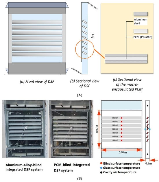
Figure 1.
The integrated system and experimental test rig: (A) scheme diagram of the integrated system; (B) installation spots for data collection [37].
Figure 1B shows the experimental test rig and installation spots for data collection. To obtain the surface temperature of the integrated system, a total of four PT100 sensors were installed on the external and internal surfaces of the outer and inner glass panes of the DSF, while fourteen PT100 sensors were mounted on the upper and lower surfaces of each blade in the blind system. To obtain the air-cavity temperature in the DSF, K-type thermocouples were fixed at appropriate locations. The DSF was naturally ventilated with air openings at the top and at the bottom of the external and internal glass wall. The developed PCM blind was installed in the DSF cavity with an original tilt angle of 30° for receiving the maximum amount of solar radiation.
2.2. PCM-Blind Development
Based on the design concept of the integrated macro-encapsulated PCM-blind system, the process of the system’s development is depicted in Figure 2. The procedure includes material selection, material characterization, and PCM-blade development. Firstly, historical weather data (ambient temperature and solar radiation) and air-cavity temperature data on a real DSF system was collected in 2022 and analyzed to identify a suitable PCM melting temperature. The analytical hierarchy process (AHP) method was adopted to select candidate PCMs. The selection criteria included thermo-physical properties, stability, safety, and cost of commercially available paraffin materials for developing the PCM blind for the DSF system. Then, during the material characterization stage, differential scanning calorimetry (DSC) tests were conducted on the candidate PCM samples to obtain the heat of fusion and the specific heat of the PCM during the melting and solidification processes. The specifications of the selected PCM are summarized in Table 2. Finally, the PCM blade was developed by utilizing a hollow rectangular aluminum-alloy tube for macro-encapsulation of the PCM. The calculated amount of melted PCM was injected into the aluminum-alloy tube, and, once solidified, the ends were sealed with epoxy adhesive and left undisturbed for over 48 h.
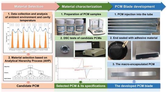
Figure 2.
Procedure used to develop the macro-encapsulated PCM blind.
Table 2.
The specifications of the selected PCM.
2.3. Data Collection and PCM Selection
Data collection was conducted in an experimental test rig placed on the roof of an office building at the University of Shanghai for Science and Technology, Shanghai, which is in a hot-summer and cold-winter region of China. Two stages of data collection were carried out, including one week of data collection (21~27 June 2022) during the overheating season on the aluminum-blind-integrated DSF for the PCM selection and data collection on a typical day (25 October 2022) during the warm season on the PCM-blind-integrated DSF for the boundary condition setup and numerical model’s validation.
Figure 3 presents the variations in the DSF air-cavity temperature with an aluminum blind from 21 to 27 June 2022. In general, the air-cavity temperature fluctuated between 25 °C and 45 °C, with the peak occurring at around 11:00 a.m. every day. Based on the average air-cavity temperature’s cumulative time, the longest duration was in the 25~30 °C range, followed by 30~35 °C, 40~45 °C, and 35~40 °C. Therefore, paraffin was selected for preparation of the PCM blind, and its technical specifications are listed in Table 2.
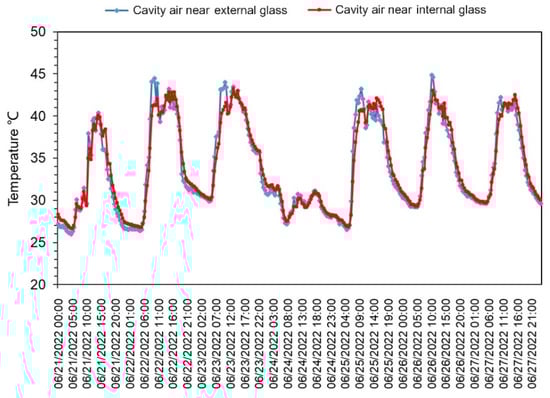
Figure 3.
Temperature profiles in the DSF system from 21 to 27 June 2022.
3. Numerical Model and Procedure
3.1. Heat Transfer Model
The heat transfer process of the integrated PCM blind and DSF system is demonstrated in Figure 4. The solar radiation that reaches the external glass wall can be divided into direct and diffuse solar irradiance [38]. A proportion of the solar radiation enters the room, while the remaining proportion is absorbed by the DSF-PCM-blind system. Long-wave radiation and convective heat transfer occur between the external glass wall and the ambient environment. The PCM blind, which is positioned in the DSF’s cavity, receives the solar radiation that penetrates through the external glass wall. Convective heat transfer between the air cavity and PCM blind, long-wave radiation between the adjacent blades, and long-wave radiation between the PCM blind and glass walls also take place in the DSF’s cavity [39]. The extra heat trapped in the DSF’s cavity can be exhausted by the natural ventilation.
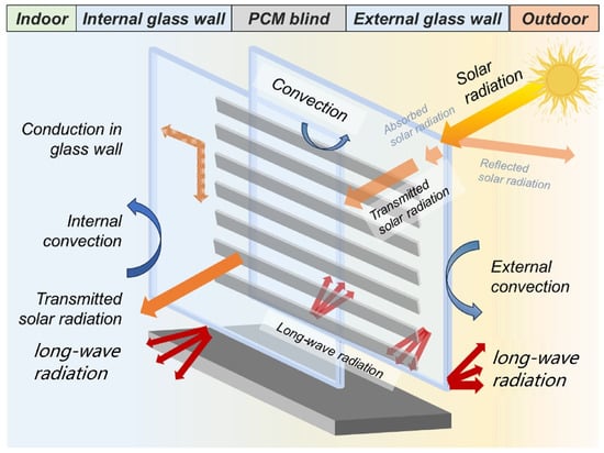
Figure 4.
Heat transfer process in the DSF and macro-encapsulated PCM.
In the establishment of the heat transfer model, we referred to our previous research [38], and it can be expressed by Equations (1)–(7).
where Qnet is the net solar radiation, Qsol is the total solar radiation, Qrefl is the reflected solar radiation, Qconv_o is the convective heat transfer on the outer mglass pane, Qconv_i is the convective heat transfer on the inner glass pane, Qabs is the absorbed solar radiation of the DSF system, Qtra is the transmitted solar heat radiation, Qb is the absorbed heat of the blind, Qrad_b1 is the radiative heat transfer on the blind, Qconv_b1 is the convective heat transfer on the blind, Gsol is the total solar irradiance, α is the absorption coefficient, is the transmittance of the DSF outer glass skin, A is the area of the glazing wall (m2), kp is the heat transfer coefficient of the PCM blind [], and Tp is the surface temperature of the blind (K).
In terms of numerical solutions for simulating the thermal behavior of PCMs, the apparent heat capacity method and the enthalpy method are commonly used [40]. The apparent heat capacity method treats the latent heat of the phase transition as a substantial apparent heat capacity within a relatively narrow temperature range, making it less suitable for modeling PCM systems with broader phase-change temperature zones. In contrast, the enthalpy method offers a superior solution for complex coupled heat exchange problems involving multiple media and boundaries. It establishes a unified energy equation across the entire region, including liquid and solid phases, as well as phase transition interfaces. It calculates the distribution of the thermal enthalpy, allowing for the delineation of phase-change interfaces [41], and eliminates the trouble of tracking phase-change interfaces or separating solid and liquid phases for independent treatment. With its advantages of high accuracy and computational efficiency, the enthalpy method is particularly well-suited for modeling PCM blinds in DSF systems and is shown in Equations (8)–(10) [42].
where H is the latent heat (J), Hs is the latent heat of the solid PCM (J), Hl is the latent heat of the liquid PCM (J), is the density (), T is the surface temperature (K), is the thermal conductivity [], is the thermal conductivity of the solid PCM [], is the thermal conductivity of the liquid PCM [], is the density of the solid PCM (), and is the density of the liquid PCM ().
3.2. CFD Model
CFD (computational fluid dynamics) is a commonly used method for simulating the thermal performance of a PCM-integrated system, since it can provide more detailed and accurate information compared with other methods [43]. This study utilized ICEM preprocessing, the pressure-based solver in ANSYS Workbench FLUENT software, and TECPLOT post-processing for analysis. The following considerations were made prior to the simulation:
- Only one-dimensional conduction was considered within each phase-change blade, while the convective heat transfer was neglected;
- The airflow within the DSF’s cavity was treated as a two-dimensional incompressible fluid;
- Long-wave radiation between the DSF-PCM-blind system and the surrounding environment were not considered;
- Viscous dissipation within the fluid flow was ignored by treating all physical parameters as constants, except for the fluid density;
- Density was only considered in relation to the momentum equation’s volume forces, while remaining constant in all other terms;
- Heat transfer through the DSF system to indoor heat gains was negligible.
3.2.1. Governing Equations
The Boussinesq approximation was used. The buoyancy effects caused by temperature differences were adopted to enhance the convergence of iterative computations. The density term in the gravity equation is represented by Equation (11), as follows:
where is the density of the fluid corresponding to (), is the fluid density corresponding to (), is the ambient temperature (°C), and is the thermal expansion coefficient.
The realizable k-ε model was chosen as the turbulence model, since it has been proven to be able to simulate heat transfer and airflow within DSF cavities [44]. For the radiation model, the discrete ordinates (DO) model was selected, since it can account for non-gray radiation, scattering effects, and radiation in semi-transparent media, which makes it suitable for modeling the DSF-PCM-blind system [45].
The PCM blind was simulated using the enthalpy method, and the energy equation can be described by Equations (12) and (13).
where h is the specific enthalpy (J/kg), href is the specific enthalpy at the reference temperature (J/kg), is the reference temperature (°C); is the enthalpy at the reference temperature (); and is the specific heat capacity at a constant pressure (.
The concept of the liquid fraction was identified in Fluent to identify the melting/solidification processes of the PCM, which is described by Equation (13).
where is the liquid fraction, T is the PCM temperature (K), is the solidification temperature of the PCM (°C), and is the melting temperature of the PCM (°C). When 0 < < 1, the PCM presents a liquid–solid two-phase state.
3.2.2. Boundary Conditions
In terms of the boundary condition setups, the weather data collected on a typical day (25 October 2022) with high air-cavity temperatures were used. The inlet airflow velocity was obtained by two hot-wire anemometers. Climatic parameters including ambient temperature and wind speed were collected using a weather station. An Agilent-DAQ-973A data logging device was employed for data collection. All the sensors and equipment were calibrated before the experiment.
The boundary condition setups are demonstrated in Table 3. The convective heat transfer coefficient between the external glass surface and the outdoor air was set at 16 W/(m2·K), and the convective heat transfer coefficient between the internal glass wall and the indoor air was 3.6 W/(m2·K), which refers to the Chinese standard [46]. The upper and lower walls were insulated. The pressure—inlet and pressure—outlet were set up as the DSF inlet and outlet boundary conditions. The wall boundary conditions were set for the external and internal glass walls. The other walls were set up as adiabatic walls. Unsteady-state simulations were conducted with a time step of 1 s. For the temperature boundary condition’s setup, outdoor temperatures were fitted to the polynomial functions (Figure 5), and the profile files were created as UDFs and imported into FLUENT. For the solar radiation’s setup, both direct and diffuse radiation data, collected at 1800s intervals using the data logger, were used (Figure 5) to create a UDF file, which was imported into FLUENT. The specifications for the air, aluminum alloy, and glass are presented in Table 4.
Table 3.
The boundary conditions used in the model.
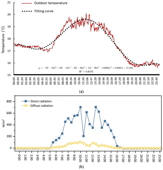
Figure 5.
Temperature and solar radiation profiles for the boundary conditions’ setup: (a) outdoor temperature and its fitting curve; (b) direct and diffuse radiation data for the solar radiation’s setup.
Table 4.
Specifications of the material used in this model.
3.2.3. Independence Test
After the geometric model was developed, unstructured meshes were generated utilizing ICEM software. Four mesh resolutions were tested (100,895-, 203,067-, 301,655-, and 404,064-cell grids) to ensure the solution’s independence. The baseline mesh consisted of polyhedral cells with prism layers near the walls, refined iteratively based on velocity gradient thresholds. In Figure 6a, the simulated temperature profiles along the centerline in the DSF cavity at Y = 55 cm for the four different grid sizes were compared. The differences among the grid sizes with 200,000, 300,000, and 400,000 grid cells were minimal, with an average error of less than 1%. Therefore, the grid size consisting of 301,655 cells (Figure 6b) was selected for further simulation as a compromise between simulation accuracy and computational resources and time.
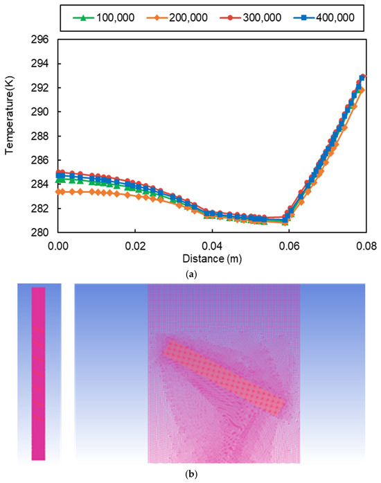
Figure 6.
Grid arrangement of the DSF and macro-encapsulated PCM-blind system: (a) grid independence results for various grid sizes; (b) grid arrangement of the DSF and macro-encapsulated PCM-blind system.
3.2.4. Model Validation
The model’s validation focused on the DSF system, since validations using room-level quantities (e.g., indoor air temperature) may lead to much higher uncertainty [47]. Therefore, the simulation’s results for the average air-cavity temperature were compared with the collected data on the PCM-blind-integrated DSF system on 25 October 2022, as presented in Figure 7. It is obvious that the trends of the measured and simulated average air-cavity temperatures are identical. The maximum values of the simulated and measured average air-cavity temperature are 40.6 °C and 40.5 °C, respectively.
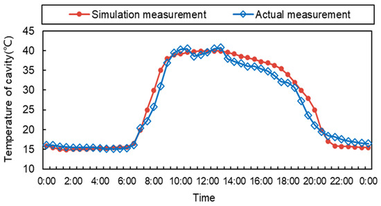
Figure 7.
Comparison of the measured and simulated average air-cavity temperatures.
In order to prove the reliability of the numerical models, the validation approaches in the ASHRAE Guidelines 14-110 [41] and the Measurement and Verification Guidelines 3.0 of the U.S. DOE [48] were adopted. According to these guidelines, the values of the mean bias error (MBE) and the root mean square error (RMSE) should be within the ranges of −10%~10% and −30%~30%, respectively. The MBE and RMSE can be calculated using Equations (14) and (15). By calculating the MBE and RMSE of the experimental data and the simulation results for the air-cavity temperature, it was found that the MBE value was 2.15%, and the RMSE value was 7.5%. The results indicate that both the MBE and RMSE values were within the recommended range suggested by the guidelines, which proved the reliability of the numerical model for simulating the DSF and PCM-blind system.
where is the simulated temperature, is the measured temperature, and is the number of comparison values.
4. Results and Discussion
4.1. System Performance on Typical Meteorological Day
Figure 8a presents the temperature contours of the DSF at the following various times: 8:00 a.m., 10:00 a.m., 12:00 a.m., 14:00 p.m., 16:00 p.m., and 18:00 p.m. on 25 October 2022. The air-cavity temperature first increased, peaked at 12:00 a.m., and then decreased as time passed, which corresponds with the outdoor temperature variations. Due to the presence of the PCM blind, the air-cavity temperature near the external glass skin could maintain a stable temperature range within 30~35 °C, which is much lower than the temperature range of the DSF with an aluminum blind.
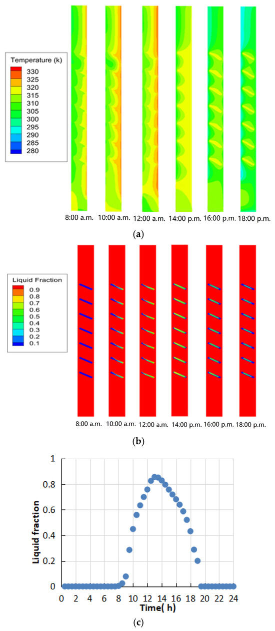
Figure 8.
Trends in the liquid fraction of the PCM blind: (a) contours of the air-cavity temperature of the DSF on a typical meteorological day; (b) liquid fraction contour of the PCM; (c) average liquid fraction of the PCM blind.
Figure 8b shows how the liquid fraction of the PCM changes within the blades over time, and Figure 8c displays the daily average liquid-phase fraction of the PCM blade. The melting process of the PCM occurred from 8:30 a.m. to 19:30 p.m. A gradual rise in the liquid-phase fraction could be witnessed from 8:30 a.m. to 13:00 p.m., which demonstrates that the macro-encapsulated PCM was able to absorb excessive heat in the DSF cavity, maintaining the cavity temperature within the desired range of 37~39 °C during the melting period. From 13:30 p.m. to 19:30 p.m., the liquid-phase fraction steadily decreased to 0 along with the solidification process. During this process, the PCM continuously released the absorbed heat and delayed the temperature drop in the DSF cavity. The highest liquid-phase fraction value was 0.86, which occurred at 13:30 p.m., which indicates that an appropriate quantity of the PCM was used.
4.2. Influence of the Blind Tilt Angle on the System’s Thermal Performance
In order to reveal the influence of the blind tilt angle on the system’s thermal performance, the following four angles were considered: 0°, 30°, 60°, and 90°. Figure 9 displays the temperature distributions within the DSF cavity at 8:00 a.m., 10:00 a.m., 12:00 a.m., 14:00 p.m., 16:00 p.m., and 18:00 p.m. When the blind tilt angle was 0°, the DSF air-cavity temperature was obviously higher than the system with other angles. The maximum air temperature reached 45 °C, which is probably due to its worst solar shading effect allowing more direct solar radiation to gather in the DSF cavity. When the blind tilt angle was 90°, a large temperature difference could be found between the external and internal glass skins. The surface temperature of the external glass skin was about 47 °C, while the temperature of the internal glass skin was 35 °C due to an effective shading effect. In general, the DSF with blind tilt angles of 30° or 60° was able to maintain the air-cavity temperatures within the range of 37~40 °C.
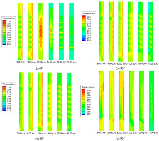
Figure 9.
The effect of the cavity air temperature contours in the DSF and macro-encapsulated PCM blind with different blind tilt angles on the system’s thermal performance.
Figure 10 demonstrates the average air-cavity temperature profiles of the integrated macro-encapsulated PCM blind and DSF system with various blind tilt angles. The temperature trends are consistent with the blind tilt angles. The 0° PCM blind had a notably higher peak temperature at 45.2 °C, while the system with blind tilt angles of 30° or 60° maintained a stable air-cavity temperature within the range of 38~40 °C. Although the 90° PCM blind also achieved a lower air-cavity temperature of about 36 °C, this would weaken the indoor lighting to a large extent. Based on the above analysis, both the 30° and 60° tilt angles are favorable choices for a PCM blind in a DSF cavity.
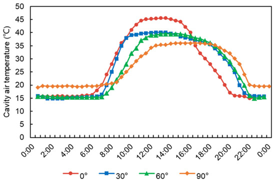
Figure 10.
DSF air-cavity temperature profiles with various blind tilt angles.
Figure 11 and Figure 12 show the profiles of the average liquid fraction of the PCM blind with different blind tilt angles. The phase-change process occurred between 8:00 a.m. and 18:00 p.m. for the PCM blind with different angles, with the peak values of the liquid fraction occurring around 13:00 p.m.~14:00 p.m. in the afternoon. In descending order of blade tilt angles (90°, 60°, 30°, and 0°), the corresponding peak liquid fraction values are 1, 0.93, 0.86, and 0.61, respectively. When the PCM was solid, the liquid fraction was first 0 and then gradually increased as it melted into a liquid state. A liquid fraction between 0 and 1 indicates a liquid–solid mixed-phase state. With a tilt angle of 90°, it took roughly an hour for the PCM to entirely melt into a liquid state. For the PCM blind with tilt angles of 60° and 30°, the liquid fractions of the PCM were similar, reaching peak values near 1.00 after sufficient heat storage (peaking at 0.93 and 0.86, respectively), indicating an appropriate PCM selection and quantity. The PCM blind with a tilt angle of 0° only achieved a maximum liquid fraction of 0.61.
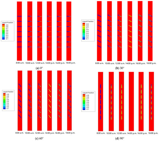
Figure 11.
Liquid fraction contours of the PCM blind with various tilt angles.
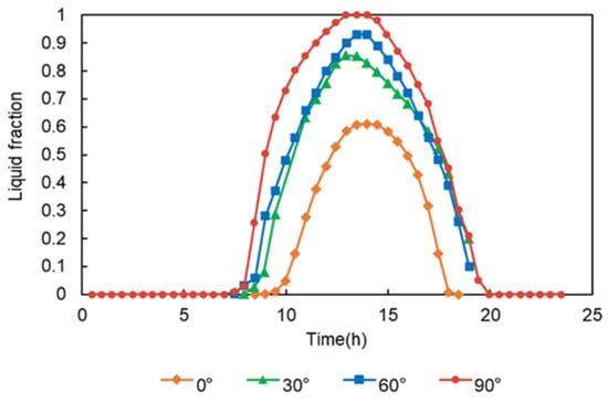
Figure 12.
Liquid fraction of the PCM blind with various blind tilt angles.
4.3. Influence of the Cavity Depth to Blind Width Ratio on the System’s Thermal Performance
Figure 13 compares four different ratios of cavity depth (X) to blind width (L), which were X = 1.5 L, X = 2 L, X = 2.5 L, and X = 3 L. The temperature distributions in the DSF cavity with X = 1.5 L, 2 L, and 2.5 L were quite similar. The average air-cavity temperature remained relatively stable between 10:00 a.m. and 14:00 p.m., fluctuating within the range of 35~42 °C. The stable air-cavity temperature resulted from the effective heat absorption by the PCM blind, which also corresponds to the temperature profiles in the DSF cavity. However, in the DSF cavity with a cavity depth to blind width ratio of X = 3 L, the air-cavity temperature fluctuated significantly between 10:00 a.m. and 16:00 p.m. At 14:00 p.m., the air near the external glass skin and the blind’s surface reached about 45 °C, while the air around the internal glass skin exceeded 40 °C. This indicates that the PCM blind struggled to reduce the cavity temperature effectively. This is probably due to the fact that the dimensions of the PCM blind had reached their upper limit for absorbing extra heat in a DSF cavity with a comparably large depth. Additionally, the larger DSF cavity size would result in a lower airflow velocity, which may weaken the convective heat transfer on the blind’s surface.
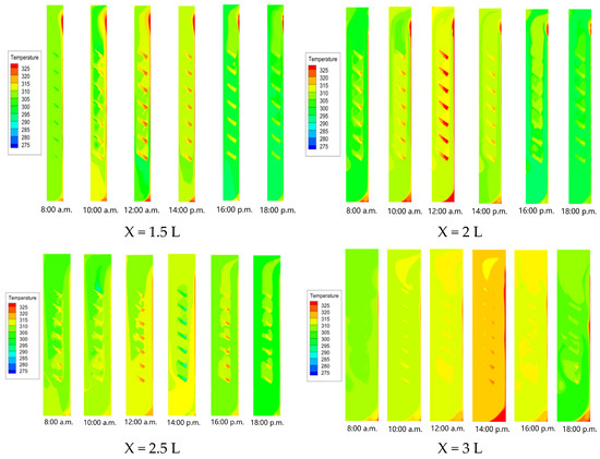
Figure 13.
Air-cavity temperature contours for the DSF and macro-encapsulated PCM blind with various cavity depth to blind width ratios.
According to Figure 14, the differences among the air-cavity temperatures near the internal glass skins with different cavity depth to blind width ratios were relatively small. As the cavity depth to blind width ratio increased, the air temperature near the external glass skin rose. Specifically, for X = 1.5 L, 2 L, and 2.5 L, the air-cavity temperatures were maintained below 42 °C, which indicates the effectiveness of the PCM blind in temperature adjustment. However, for X = 3 L, the front-side cavity temperature peaked at 46 °C, suggesting that the PCM blind struggled to efficiently absorb excessive heat from the air cavity.
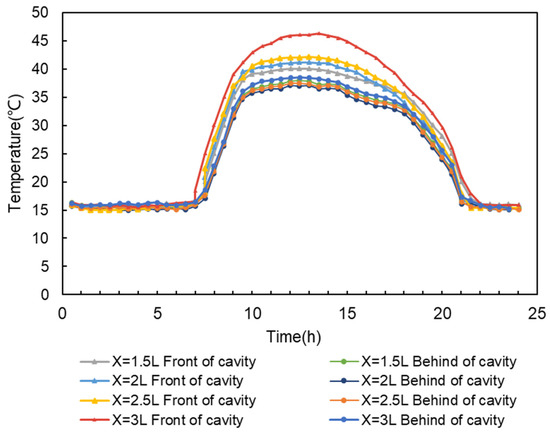
Figure 14.
DSF air-cavity temperature profiles with different ratios of cavity depth to blind width.
Based on the above analysis, Figure 15 compares the average air-cavity temperatures between the original experimental setup and the optimized design parameters. It demonstrates that adjusting a cavity width ratio of X = 2.5 L could effectively reduce the air-cavity temperature and eliminate the overheating effect during the daytime mid-season. The maximum temperature may decrease by 2.9 °C and the average cavity temperature could drop by 1.2 °C during the time period from 7:30 a.m. to ~21:30 p.m.
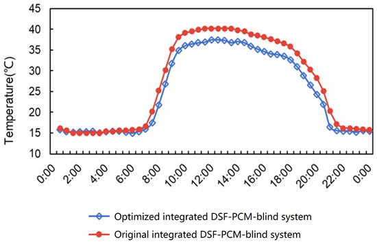
Figure 15.
Comparison of the air-cavity temperatures before and after optimization.
5. Conclusions
This study was aimed at investigating the influence of design parameters on the thermal performance of a macro-encapsulated PCM blind within a DSF system. Numerical models were developed, and CFD simulations were conducted using ANSYS Workbench FLUENT software. Experimental data were then collected from a DSF system equipped with both aluminum blinds and PCM blinds for validation of the model. The temperature distributions within the DSF cavity were compared across various blind tilt angles and cavity depth to blind width ratios. Based on these findings, optimized design parameters for the integrated system are proposed. The main conclusions are summarized as follows:
- The PCM blind was able to absorb the excessive heat in the DSF cavity for an average duration of 5.9 h, providing the smallest range of temperature change, which indicates this system can be utilized to optimize thermal environmental impacts based on real-time conditions;
- The air temperature at different positions for the previous DSF test ranged from 39 to ~40 °C. Both the surface temperature of the PCM blind and the air-cavity temperature in the DSF could be maintained within the range of 37~40 °C by optimizing the design parameters. The optimal design parameters can improve the thermal performance of the macro-encapsulated PCM-blind integrated into the DSF system;
- The lowest PCM-layer surface temperature can be achieved with a blind tilt angle of 30° in the DSF system. Moreover, the blind tilt angles of 30° and 60° are recommended, since they demonstrated better temperature adjustment effects in the DSF cavity, with cavity temperature stabilized in the range of 38~40 °C;
- The cavity depth to blind width ratio of X = 2.5 L was recommended as optimal, since it could effectively reduce the air-cavity temperature and eliminate the overheating effect during the daytime in the warm season.
This study demonstrates that macro-encapsulated PCM blinds with aluminum shells can serve as an effective passive solution for mitigating overheating in double-skin façades (DSFs) within China’s hot-summer, cold-winter climate zone. However, several limitations remain, and potential avenues for further research are outlined below. Firstly, the thermal performance of the optimized macro-encapsulated PCM and DSF system across the entire year warrants further investigation, particularly under varying seasonal conditions. This would provide a more comprehensive understanding of its effectiveness in both extreme and transitional climate phases. Additionally, a direct comparison between the performance of the macro-encapsulated system and a micro-encapsulated system is necessary to assess the relative advantages and challenges of each approach, especially in terms of efficiency, cost, and long-term durability. Furthermore, a life-cycle assessment (LCA) and cost analysis of the PCM-blind system are critical for evaluating its economic feasibility and sustainability. Such an assessment would offer valuable insights into the practical implications of adopting this technology in building design and construction, particularly for large-scale or long-term applications.
Author Contributions
Conceptualization, Y.L. (Yilin Li); Methodology, W.H., C.Y. and Y.L. (Yidong Li); Software, Y.L. (Yidong Li); Formal analysis, W.H., W.T. and C.Y.; Resources, J.D.; Data curation, W.T.; Writing—original draft, Y.L. (Yilin Li) and W.H.; Writing—review & editing, J.D.; Visualization, W.T.; Supervision, Y.L. (Yilin Li); Funding acquisition, Y.L. (Yilin Li). All authors have read and agreed to the published version of the manuscript.
Funding
This research was funded by the National Natural Science Foundation of China (grant no. 52008245), the foundation of Jiangsu Province Engineering Research Center of Construction Carbon Neutral Technology (grant no. JZTZH2023-0201), Key Laboratory of Ecology and Energy Saving Study of Dense Habitat, Ministry of Education (grant no. 20230102), and Shanghai Sailing Program (grant no. 20YF1432000).
Data Availability Statement
Dataset available on request from the authors.
Conflicts of Interest
The authors declare no conflict of interest.
List of Symbols
| Nomenclature | Subscript | ||
| A | area(m2) | net | net heat gain of DSF |
| Cp | specific heat (J/(kg·K)) | sol | total solar radiation on DSF |
| Q | heat (J) | refl | reflected solar radiation |
| H | enthalpy (J) | ref | reference value |
| ΔH | latent heat (J) | abs | absorbed solar radiation |
| T | temperature (K) | tra | transmitted solar radiation |
| ΔT | temperature difference (K) | 1 | external glass skin of the DSF |
| h | convective heat transfer coefficient (W/(m2·K))/specific enthalpy (J/kg) | 2 | internal glass skin of the DSF |
| k | thermal conductivity (W/(m·K)) | rad | radiative heat transfer |
| ρ | density (kg/m3) | b | blind |
| ν | kinematic viscosity | k | turbulence kinetic energy |
| α | absorption coefficient/expansion coefficient of air | i | indoor |
| τ | transmittance of the DSF outer glass skin/time | o | outdoor |
| λ | thermal conductivity coefficient [W/(m·K)] | m | phase transformation |
| β | thermal expansion coefficientliquid fraction | s | solid |
| Si | simulated temperature | l | liquid |
| Mi | measured temperature | cex | air near the external glass wall |
| n | number of comparison values | cin | air near the internal glass wall |
| convp | convective heat transferof PCM layer of the blind | ||
References
- Srithapon, C.; Månsson, D. Predictive control and coordination for energy community flexibility with electric vehicles, heat pumps and thermal energy storage. Appl. Energy 2023, 347, 121500. [Google Scholar] [CrossRef]
- Yun, B.Y.; Park, J.H.; Yang, S.; Wi, S.; Kim, S. Integrated analysis of the energy and economic efficiency of PCM as an indoor decoration element: Application to an apartment building. Sol. Energy 2020, 196, 437–447. [Google Scholar] [CrossRef]
- Dardouri, S.; Mankai, S.; Almoneef, M.M.; Mbarek, M.; Sghaier, J. Energy Performance Based Optimization of Building Envelope Containing PCM Combined with Insulation Considering Various Configurations. Energy Rep. 2023, 10, 895–909. [Google Scholar] [CrossRef]
- Lee, S.M.; Kim, D.Y.; An, J.H.; Lee, C.S.; Shin, U.C. Availability Evaluation of Korea Window Energy Consumption Efficiency Rating System for the Office Building. Korean J. Air-Cond. Refrig. Eng. 2019, 31, 464–472. [Google Scholar] [CrossRef]
- Grynning, S.; Gustavsen, A.; Time, B.; Jelle, B.P. Windows in the Buildings of Tomorrow; Energy Losers or Energy Gainers. Energy Build. 2013, 61, 185–192. [Google Scholar] [CrossRef]
- Tanimoto, J.; Kimura, K.I. Simulation study on an air flow window system with an integrated roll screen. Energy Build. 1997, 26, 317–325. [Google Scholar] [CrossRef]
- Bruno, R.; Bevilacqua, P. Bio-PCM to Enhance DynAMic Thermal Properties of Dry-Assembled Wooden Walls: Experimental Results. Build. Environ. 2023, 242, 110526. [Google Scholar] [CrossRef]
- Abilkhassenova, Z.; Memon, S.A.; Ahmad, A.; Saurbayeva, A.; Kim, J. Utilizing the Fanger Thermal Comfort Model to Evaluate the Thermal, Energy, Economic, and Environmental Performance of PCM-Integrated Buildings in Various Climate Zones Worldwide. Energy Build. 2023, 297, 113479. [Google Scholar] [CrossRef]
- Izadi, M.; Afsharpanah, F.; Mohadjer, A.; Shobi, M.O.; Ajarostaghi, S.S.M.; Minelli, F. Performance enhancement of a shell-and-coil ice storage enclosure for air conditioning using spiral longitudinal fins: A numerical approach. Heliyon 2025, 11, e42786. [Google Scholar] [CrossRef]
- Yasiri, Q.; Szabó, M. Incorporation of Phase Change Materials into Building Envelope for Thermal Comfort and Energy Saving: A Comprehensive Analysis. J. Build. Eng. 2021, 36, 102122. [Google Scholar] [CrossRef]
- Kishore, R.A.; Bianchi, M.V.; Booten, C.; Vidal, J.; Jackson, R. Optimizing PCM-Integrated Walls for Potential Energy Savings in U.S. Buildings. Energy Build. 2020, 226, 110355. [Google Scholar] [CrossRef]
- Mokhberi, P.; Mokhberi, P.; Izadi, M.; Nesaii, M.B.; Yaici, W.; Minelli, F. Thermal regulation enhancement in multi-story office buildings: Integrating phase change materials into inter-floor void formers. Case Stud. Therm. Eng. 2024, 60, 104792. [Google Scholar] [CrossRef]
- Rathore, P.K.S.; Shukla, S.K.; Gupta, N.K. Yearly analysis of peak temperature, thermal amplitude, time lag and decrement factor of a building envelope in tropical climate. J. Build. Eng. 2020, 31, 101459. [Google Scholar] [CrossRef]
- Bao, X.; Yang, H.; Xu, X.; Xu, T.; Cui, H.; Tang, W.; Sang, G.; Fung, W. Development of a stable inorganic phase change material for thermal energy storage in buildings. Sol. Energy Mater. Sol. Cells 2020, 208, 110420. [Google Scholar] [CrossRef]
- Li, D.; Hu, W.; Zhang, C.; Liu, C.; Yang, R. Study on energy storage characteristics of phase change glass envelope and its impact on indoor thermal environment. J. Xi’an Univ. Archit. Technol. (Nat. Sci. Ed.) 2021, 53, 934–938. [Google Scholar] [CrossRef]
- Weinläder, H.; Beck, A.; Fricke, J. PCM-facade-panel for daylighting and room heating. Sol. Energy 2005, 78, 177–186. [Google Scholar] [CrossRef]
- Weinlaeder, H.; Koerner, W.; Heidenfelder, M. Monitoring results of an interior sun protection system with integrated latent heat storage. Energy Build. 2011, 43, 2468–2475. [Google Scholar] [CrossRef]
- Alawadhi, E.M. Using phase change materials in window shutter to reduce the solar heat gain. Energy Build. 2012, 47, 421–429. [Google Scholar] [CrossRef]
- Silva, T.; Vicente, R.; Rodrigues, F.; Samagaio, A.; Cardoso, C. Performance of a window shutter with phase change material under summer Mediterranean climate conditions. Appl. Therm. Eng. 2015, 84, 246–256. [Google Scholar] [CrossRef]
- Li, Y.; Darkwa, J.; Kokogiannakis, G. Heat Transfer Analysis of an Integrated Double Skin Facade and Phase Change Material Blind System. Build. Environ. 2017, 125, 111–121. [Google Scholar] [CrossRef]
- Li, Y.; Darkwa, J.; Kokogiannakis, G.; Su, W. Phase change material blind system for double skin façade integration: System development and thermal performance evaluation. Appl. Energy 2019, 252, 113376. [Google Scholar] [CrossRef]
- Cabeza, L.F.; Navarro, L.; Pisello, A.L.; Olivieri, L.; Bartolomé, C.; Sánchez, J.; Álvarez, S.; Tenorio, J.A. Behaviour of a concrete wall containing micro-encapsulated PCM after a decade of its construction. Sol. Energy 2020, 200, 108–113. [Google Scholar] [CrossRef]
- Dubey, A.K.; Sun, J.; Choudhary, T.; Dash, M.; Rakshit, D.; Ansari, M.Z.; Ramakrishna, S.; Liu, Y.; Nanda, H.S. Emerging phase change materials with improved thermal efficiency for a clean and sustainable environment: An approach towards net zero. Renew. Sustain. Energy Rev. 2023, 182, 113421. [Google Scholar] [CrossRef]
- Li, Q.; Wang, Y.; Ma, L.; Arıcı, M.; Li, D.; Yıldız, Ç.; Zhu, Y. Effect of sunspace and PCM louver combination on the energy saving of rural residences: Case study in a severe cold region of China. Sustain. Energy Technol. Assess. 2021, 45, 101126. [Google Scholar] [CrossRef]
- Rehman, O.A.; Palomba, V.; Verez, D.; Borri, E.; Frazzica, A.; Brancato, V.; Botargues, T.; Ure, Z.; Cabeza, L.F. Experimental evaluation of different macro-encapsulation designs for PCM storages for cooling applications. J. Energy Storage 2023, 74, 109359. [Google Scholar] [CrossRef]
- Zhan, H.; Mahyuddin, N.; Sulaiman, R.; Khayatian, F. Phase change material (PCM) integrations into buildings in hot climates with simulation access for energy performance and thermal comfort: A review. Constr. Build. Mater. 2023, 397, 132312. [Google Scholar] [CrossRef]
- Abdulmunem, A.R.; Hussein, N.F.; Samin, P.M.; Sopian, K.; Hussien, H.A.; Ghazali, H. Integration of recycled waste paper with phase change material in building enclosure. J. Energy Storage 2023, 64, 107140. [Google Scholar] [CrossRef]
- Atiganyanun, S.; Hasuchon, C.; Prithan, K.; Wongwan, K.; Kumnorkaew, P. Inclusion of microencapsulated phase change materials in waterborne paints to enhance radiative cooling performance. Mater. Today Proc. 2023. [Google Scholar] [CrossRef]
- Fukahori, R.; Nomura, T.; Zhu, C.; Sheng, N. Macro-encapsulation of metallic phase change material using cylindrical-type ceramic containers for high-temperature thermal energy storage. Appl. Energy 2016, 170, 324–328. [Google Scholar] [CrossRef]
- Zhou, X.; Yamashita, S.; Kubota, M.; Zhang, C.; Hong, F.; Kita, H. Macro encapsulated Cu-based phase change material for high temperature heat storage with characteristic of self-sealing and high durability. Appl. Therm. Eng. 2023, 229, 120491. [Google Scholar] [CrossRef]
- Kitagawa, H.; Asawa, T.; Kubota, T.; Trihamdani, A.R. Numerical simulation of radiant floor cooling systems using PCM for naturally ventilated buildings in a hot and humid climate. Build. Environ. 2022, 226, 109762. [Google Scholar] [CrossRef]
- Chen, W.; Liu, Y.; Liang, X.; Luo, F.; Liao, T.; Wang, S.; Gao, X.; Zhang, Z.; Fang, Y. Experimental and numerical investigations on radiant floor heating system integrated with macro-encapsulated phase change material. Energy 2023, 282, 128375. [Google Scholar] [CrossRef]
- Che-Pan, M.; Simá, E.; Ávila-Hernández, A.; Uriarte-Flores, J.; Vargas-López, R. Thermal performance of a window shutter with a phase change material as a passive system for buildings in warm and cold climates of México. Energy Build. 2023, 281, 112775. [Google Scholar] [CrossRef]
- Yang, S.; Zhang, Y.; Zhao, Y.; Torres, J.F.; Wang, X. PCM-based ceiling panels for passive cooling in buildings: A CFD modelling. Energy Build. 2023, 285, 112898. [Google Scholar] [CrossRef]
- Rešetar, I.; Jurtz, N.; Böhm, L.; Kraume, M.; Palz, N. Integrated Framework for digital design and thermal analysis of PCM macro-encapsulations for passive indoor cooling. Sustain. Cities Soc. 2021, 66, 102536. [Google Scholar] [CrossRef]
- IllAMpas, R.; Rigopoulos, I.; Ioannou, I. Influence of microencapsulated Phase Change Materials (PCMs) on the properties of polymer modified cementitious repair mortar. J. Build. Eng. 2021, 40, 102328. [Google Scholar] [CrossRef]
- Li, Y.; Fu, S.; Li, Y.; Peng, Y.; Yang, C.; Tao, W.; Wang, H. Seasonal thermal performance of a macro-encapsulated phase change material blind integrated double skin façade system: An experimental study. Energy Build. 2024, 325, 114952. [Google Scholar] [CrossRef]
- Oh, M.; Kim, C.K.; Kim, B.; Yun, C.; Kim, J.-Y.; Kang, Y.; Kim, H.-G. Analysis of minute-scale variability for enhanced separation of direct and diffuse solar irradiance components using machine learning algorithms. Energy 2022, 241, 122921. [Google Scholar] [CrossRef]
- Lucchino, E.C.; Gelesz, A.; Skeie, K.; Gennaro, G.; Reith, A.; Serra, V.; Goia, F. Modelling double skin façades (DSFs) in whole-building energy simulation tools: Validation and inter-software comparison of a mechanically ventilated single-story DSF. Build. Environ. 2021, 199, 107906. [Google Scholar] [CrossRef]
- Zeng, X.; Xin, M. Numerical enthalpy method for solving multidimensional phase change heat transfer problems with coupled enthalpy and moving boundary position. J. Chongqing Univ. (Nat. Sci. Ed.) 1992, 03, 62–67. [Google Scholar]
- ASHRAE. ASHRAE Guideline 14-2023 Measurement of Energy, Demand, and Water Savings, American Society of Heating, Refrigerating and Air-Conditioning Engineers. 2023, pp. 58–62. Available online: www.ashrae.org/G14 (accessed on 17 June 2025).
- Geng, Z.; Shi, C.; Zhao, Q.; Yang, L. Preparation of diatomite paraffin composite phase change coating and its simulation application in building wall. J. Energy Storage 2024, 83, 110543. [Google Scholar] [CrossRef]
- Chen, G.; Hang, J.; Chen, L.; Lin, Y. Comparison of uniform and non-uniform surface heating effects on in-canyon airflow and ventilation by CFD simulations and scaled outdoor experiments. Build. Environ. 2023, 244, 110744. [Google Scholar] [CrossRef]
- Hazem, A.; AMeghchouche, M.; Bougriou, C. A numerical analysis of the air ventilation management and assessment of the behavior of double skin facades. Energy Build. 2015, 102, 225–236. [Google Scholar] [CrossRef]
- Mojumder, J.C.; AMinossadati, S.M.; Leonardi, C.R. Performance analysis of a concentrated direct absorption solar collector (DASC) with nanofluids using computational fluid dynamics and discrete ordinates radiation modelling (CFD-DORM). Renew. Energy 2023, 205, 30–52. [Google Scholar] [CrossRef]
- JGJ/T 151-2018; Calculation specification for thermal performance of windows and doors. Ministry of Housing and Urban-Rural Development of the People’s Republic of China. China Architecture & Building Press: Beijing, China, 2018.
- Lucchino, E.C.; Gennaro, G.; Favoino, F.; Goia, F. Modelling and validation of a single-storey flexible double-skin façade system with a building energy simulation tool. Build. Environ. 2022, 226, 109704. [Google Scholar] [CrossRef]
- U.S. Department of Energy. Federal Energy Management Program, Measurement and Verification Guidelines: Measurement and Verification for Federal Energy Projects Version 3.0; U.S. Department of Energy: Washington, DC, USA, 2008.
Disclaimer/Publisher’s Note: The statements, opinions and data contained in all publications are solely those of the individual author(s) and contributor(s) and not of MDPI and/or the editor(s). MDPI and/or the editor(s) disclaim responsibility for any injury to people or property resulting from any ideas, methods, instructions or products referred to in the content. |
© 2025 by the authors. Licensee MDPI, Basel, Switzerland. This article is an open access article distributed under the terms and conditions of the Creative Commons Attribution (CC BY) license (https://creativecommons.org/licenses/by/4.0/).