1. Introduction
The VNS is envisioned as a complementary facility to major fusion experiments like ITER and DONES [
1,
2,
3], focusing on distinct but synergistic objectives. ITER aims to explore burning plasma physics, while DONES specialises in developing neutron-resistant structural materials. In contrast, the VNS is dedicated to testing and qualifying fully integrated in-vessel components built with essential fusion technologies [
4]. First conceptualised in 1985 [
5] and formally proposed in 1995 as a support initiative for ITER [
6], the VNS seeks to address a unique set of challenges with a more streamlined approach to plasma performance. Unlike ITER, where achieving high plasma temperatures is critical, the VNS relies on an external neutral beam (NB) system to provide the energy required for fusion reactions, reducing the complexity of plasma performance requirements [
6]. The device is designed with a major radius of 2.53 m, a single-null divertor configuration, and four tangential 120 keV beamlines capable of generating approximately 30 MW of fusion power. These beamlines also sustain steady-state plasma conditions via current drive. A compact minor plasma radius of a = 0.55 m ensures a high neutron wall load, reaching up to 0.5 MW/m
2, comparable to ITER’s benchmarks. The VNS provides approximately 25 m
2 of blanket testing area, including four port plugs, offering substantial flexibility for diverse testing scenarios, instrumentation setups, and experimental conditions. Although the plasma volume is smaller, the tokamak allocates significant space for neutron shielding structures, which are comparable in size to those in ITER. To minimise construction risks, the design incorporates many ITER-inspired concepts while also introducing customised or innovative solutions informed by ITER’s operational experience. With its relatively modest fusion power output, the VNS is expected to consume less than 1 kg of tritium annually, an amount that can be supplied from external sources [
7]. This combination of innovative design, efficient resource use, and a focused mission highlights the VNS’s role as an essential complement to broader fusion research efforts. The main features of the VNS tokamak are reported in
Table 1.
VNS tokamak, just like other fusion reactors, requires robust thermal shielding to protect sensitive components (especially superconducting magnets) from intense heat and radiation. Thermal shields serve as a heat barrier between hot structures (like the vacuum vessel and plasma-facing components) and the cryogenically cooled magnet systems. Thermal shields (TS) in superconducting fusion reactors have the primary role of minimising thermal radiation from warm components to the magnets at ~4 K. In devices like ITER [
8,
9] and DEMO [
10], the vacuum vessel can operate at up to a few hundred °C (ITER’s vacuum vessel ~100–200 °C, DEMO’s ~200 °C) while the surrounding cryostat wall is at room temperature. Without shielding, these hot surfaces would radiate large heat loads to the 4 K magnets. Key design requirements and challenges include:
High Thermal Performance: To minimise radiative heat transfer, thermal shields must function as optically opaque barriers, achieved through low-emissivity surfaces (typically silver-coated with ε < 0.05) and active cooling to intermediate temperatures (80–100 K). This reduces thermal radiation by several orders of magnitude. The primary heat load on the shields arises from radiation emitted by the vacuum vessel, with minor contributions from conductive heat transfer through structural supports. Consequently, conductive pathways (e.g., mounting brackets and support struts) must be minimised or constructed from low-thermal-conductivity materials to mitigate heat leakage.
Material Selection: Materials must balance thermal conductivity (for cooling effectiveness) with electrical resistivity (to limit eddy currents), structural strength at cryogenic temperatures, and compatibility with vacuum. Common choices are stainless steel (used in ITER/DEMO shields [
8,
9,
10]), which is structurally robust and has moderate conductivity, or copper alloys (used in W7-X [
11]), which have high thermal conductivity but require careful design to avoid large electromagnetic loads. Surfaces are typically silver-plated to maintain low emissivity. Multi-layer insulation (dozens of layers of aluminised Kapton or Mylar) is often added on shield surfaces to further cut radiation.
Active Cooling: Thermal shields are actively cooled, typically using gaseous helium at ~80 K circulated through welded cooling tubes. For instance, ITER employs pressurised helium at ~80 K [
8] and W7-X utilises helium flow through pipes connected to shield panels [
11]. The cooling system must accommodate steady-state and transient heat loads while maintaining shield temperatures within the 80–120 K range. Design considerations include uniform cooling distribution and manageable pressure drops for cryoplant efficiency.
Electromagnetic Loads: In tokamaks, transient events such as plasma disruptions or magnet quenches induce substantial eddy currents in conductive structures. Stellarators like W7-X (which lack plasma disruptions) still experience eddy currents during rapid magnet energy dumps [
11]. These currents generate Lorentz forces, necessitating design strategies to mitigate mechanical stress. Key approaches include Segmentation of the shield to restrict eddy current loops and Use of high-resistivity materials (e.g., W7-X selected brass [CuZn37] over copper for its lower eddy current generation [
11]). Tokamaks such as ITER inherently limit eddy currents through sector-based assembly, but careful structural design remains essential to withstand forces during fast discharges or asymmetric events [
8].
Neutron Irradiation and Integration: Although primarily a thermal component, the shield operates in a nuclear environment (particularly in ITER and DEMO), requiring resistance to neutron/gamma irradiation and associated heating. DEMO’s shield must additionally account for nuclear heating of the magnets—a factor absent in current experiments [
8]. The shield’s design must also accommodate spatial constraints imposed by neutron shielding blankets and vacuum vessel integration, while ensuring long-term reliability of cooling systems under cyclic thermal and radiation-induced stresses.
Table 2 reviews thermal shield technology in several major fusion devices like ITER, W7-X, and the planned DEMO reactor, highlighting key design challenges, materials and cooling strategies.
2. Aim of This Study
The primary aim of this study is to develop, evaluate, and optimise the design of the Thermal Shield (TS) for the Volumetric Neutron Source (VNS) tokamak using a multidisciplinary simulation approach. The TS is a critical component within the VNS architecture, responsible for minimising radiative heat transfer from high-temperature components to the cryogenically cooled superconducting magnets. Given the challenging operational environment of fusion reactors, the TS must simultaneously satisfy three key performance criteria: thermal insulation efficiency, electromagnetic compatibility, and mechanical robustness.
To achieve these objectives, this work integrates electromagnetic (EM), structural, and thermal finite element analyses to guide an iterative design and optimisation process. The approach emphasises the realistic assessment of the following:
Electromagnetic loading, arising from rapid coil discharges and transient magnetic field variations;
Structural integrity, particularly in relation to stress distribution, displacement, and buckling stability under pre-stressed conditions;
Thermal performance, with a focus on maintaining the TS operational temperature (approximately 80 K) and minimising temperature gradients.
3. Design Concepts
This study investigates multiple design configurations, including the following:
A Simple Panel Design without reinforcements;
A Reinforced Panel Design incorporating longitudinal and transverse stiffening ribs;
A Smaller Panel Design with strategically placed cuts to disrupt eddy current paths and reduce EM forces.
Each design was subjected to a series of parametric analyses, exploring variations in material selection (e.g., Al-1100, Al-7075), panel thickness, support layout, and rib geometry, to determine optimal configurations that meet the demanding operational constraints of the VNS. Ultimately, this study aims to propose a feasible and integrable TS design that can withstand the coupled thermal, mechanical, and electromagnetic conditions of the VNS environment.
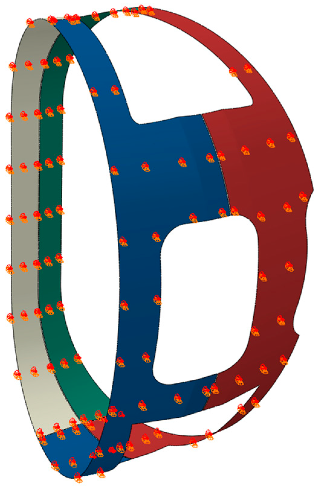
3.1. Simple Panel Design
The initial design concept of the Thermal Shield was based on the use of a lightweight material with high thermal conductivity, leading to the selection of aluminium alloy 1100 (Al-1100) as the reference material. Al-1100 offers excellent thermal conduction characteristics, making it well-suited for minimising radiative heat transfer. However, its mechanical strength is relatively limited, which presents challenges under structural loading conditions. This preliminary configuration, referred to as the
Simple Panel Design, consists of four discrete panels arranged with a single division in both the toroidal and poloidal directions, as illustrated in
Figure 1. The panels are supported by a total of 122 support points (connections between TS and VV), whose spatial distribution is illustrated by red points. The design ensures that each panel remains electrically isolated from adjacent ones to prevent the formation of closed-loop paths for induced currents, thereby mitigating the generation of electromagnetic (EM) loads during transient magnetic events. Several iterations of analyses were performed using this design, varying the panel thickness to investigate its influence on mechanical performance. Additionally, a second set of simulations was conducted using aluminium alloy 7075 (Al-7075), which provides significantly improved mechanical properties, to assess its potential in addressing the limitations observed with Al-1100.
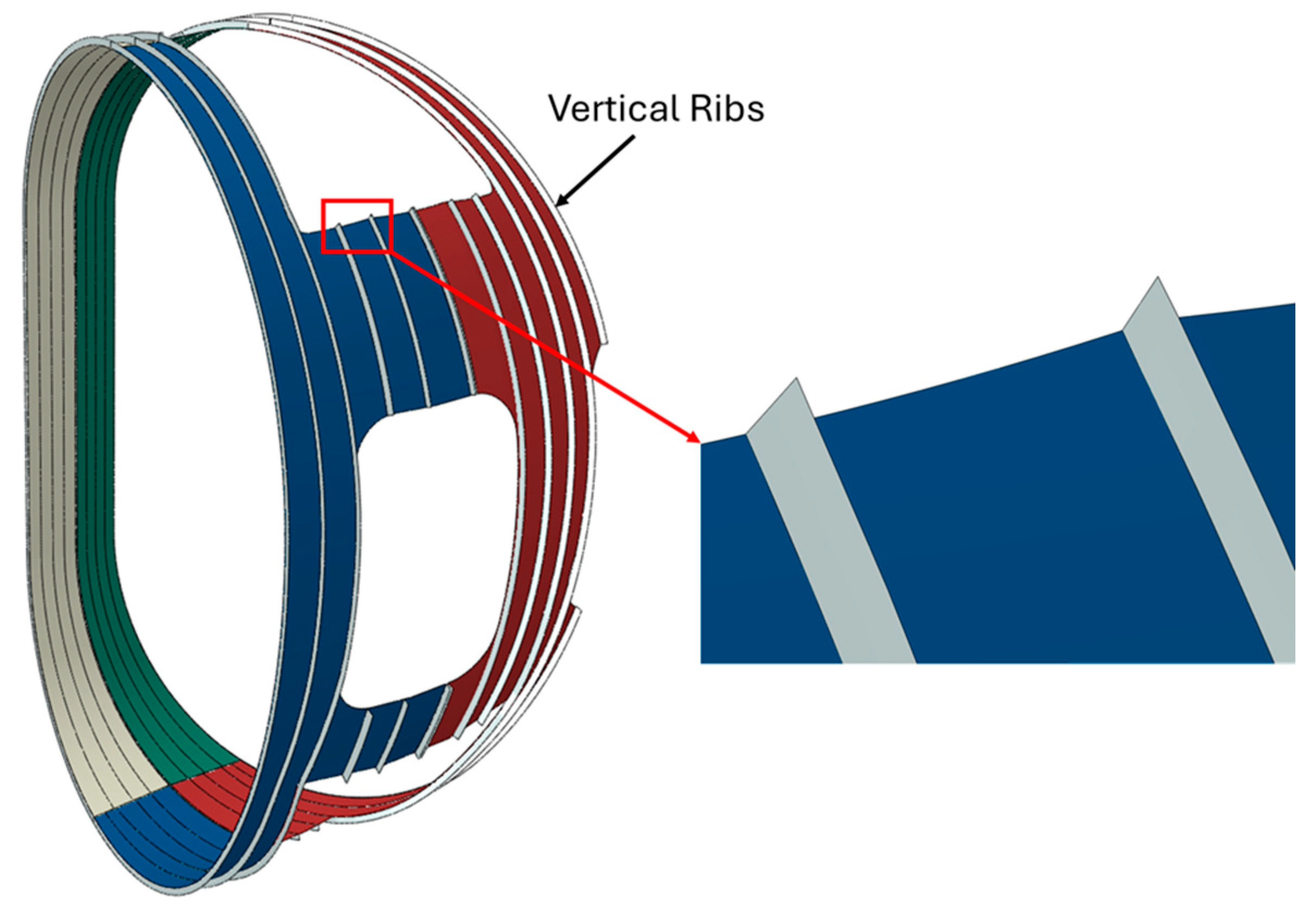
3.2. Panel + Ribs Design
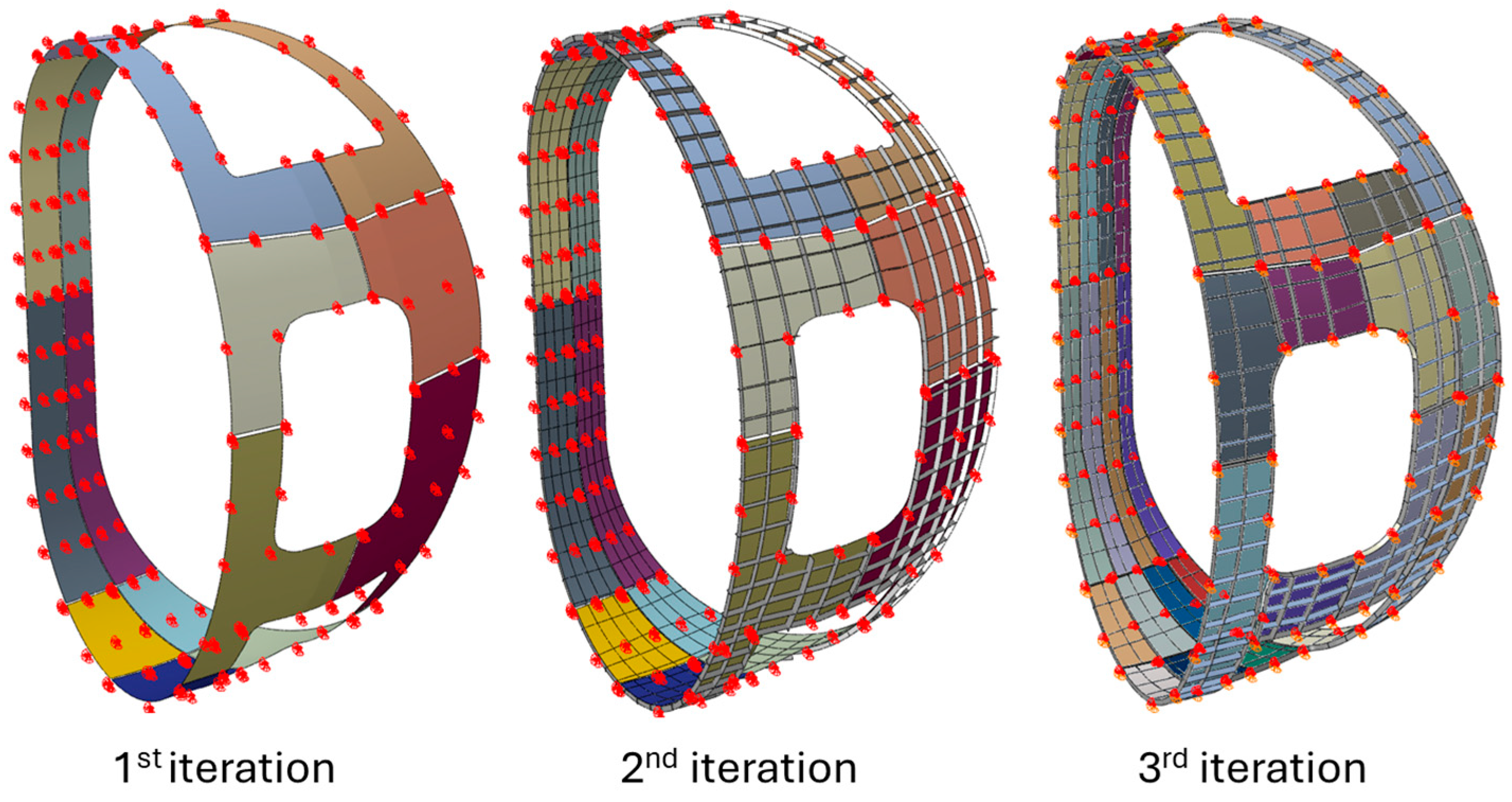
In this design concept, the configuration progressively evolved through the introduction of structural reinforcements in the form of stiffening ribs. Three iterations were developed and analysed to evaluate the impact of reinforcement strategies on mechanical performance:
First Iteration: Reinforcement ribs were introduced exclusively in the vertical direction to enhance structural rigidity while maintaining a constant panel thickness of 4 mm. The ribs, made from aluminium alloy 7075 (Al-7075), were spaced at approximately 200 mm intervals, with a height of 40 mm and a thickness of 10 mm. A total of 122 support points were distributed across the structure, as illustrated in
Figure 2.
Second Iteration: This iteration expanded upon the previous design by incorporating both vertical and transverse ribs. The rib network follows a 200 mm spacing pattern in both directions, with the same geometric parameters as in the first iteration (40 mm height, 10 mm thickness). The panel thickness remained fixed at 4 mm, considered optimal from a manufacturability perspective. The number of supports increased to 227, all strategically located at the intersections of the rib grid to maximise structural effectiveness. (
Figure 3)
Third Iteration: Building on the second iteration, this configuration retained the same rib layout but significantly increased the number of supports to 587, aiming to further improve buckling resistance and load distribution. The support layout for all three iterations is detailed in
Figure 4.
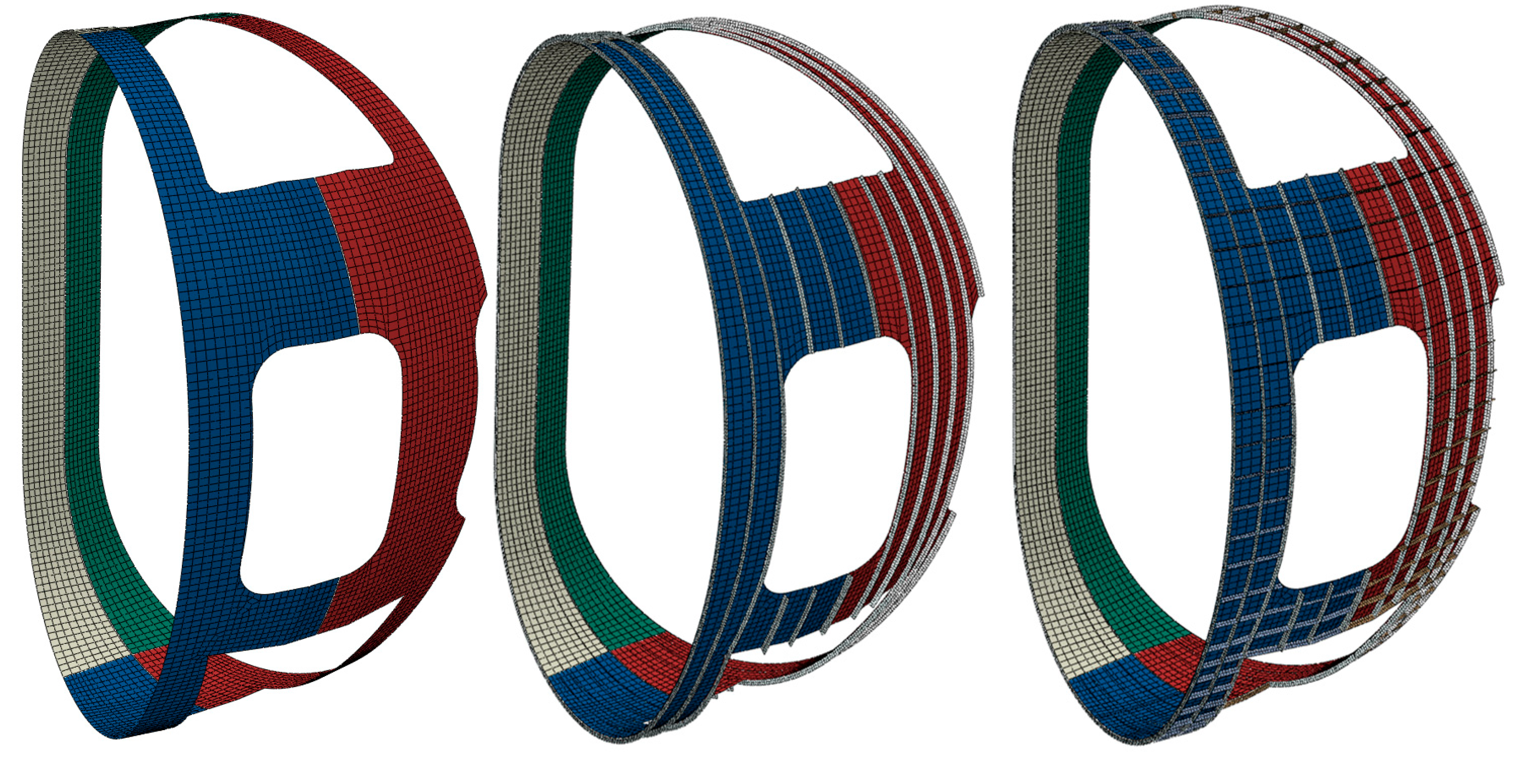
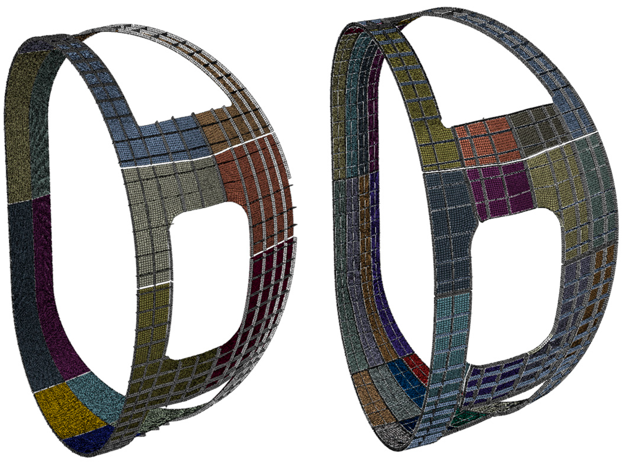
3.3. Smaller Panel Design
To mitigate the electromagnetic forces induced during transient events, additional cuts were introduced into the panels, segmenting them into smaller subsections as illustrated in
Figure 5. This strategy effectively disrupts closed-loop current paths, thereby reducing the magnitude of induced currents and the resulting Lorentz forces. Both aluminium alloy 1100 and 7075 are evaluated as the material for both the panels and reinforcement ribs. Four iterative configurations of this design concept were developed and evaluated, as described below:
First Iteration: The first intervention consisted of a toroidal cut. In this step, the TS is divided into 16 smaller panels to reduce electromagnetic load coupling. A total of 151 supports are implemented across the configuration.
Second Iteration: Building on the first configuration, this iteration incorporates reinforcement ribs to enhance mechanical stability. The ribs are uniformly distributed at 200 mm intervals, with each rib having a height of 40 mm and a thickness of 10 mm. The support count remains at 151.
Third Iteration: In this step, the panel segmentation is further refined by adding vertical cuts, resulting in a total of 32 smaller panels. The reinforcement rib layout remains consistent with previous iterations—spaced at 200 mm with 40 mm height and 10 mm thickness. To accommodate the new geometry and improve structural integrity, the number of supports is increased to 170. The list of design concepts is reported in
Table 3.
4. Analysis Methodology
To ensure the functional reliability and integrative performance, a comprehensive multiphysics simulation framework was developed. This methodology encompasses electromagnetic (EM), structural, and thermal analyses, each addressing a critical aspect of the TS behaviour under operational conditions. The analysis process is structured to reflect the sequential interaction between physical phenomena: electromagnetic simulations are first conducted to quantify induced current densities and resulting Lorentz forces generated during dynamic magnetic events such as coil charge and discharge. These forces serve as input for the structural simulations, which evaluate deformation, stress distribution, and buckling stability of the TS components. Finally, a steady-state thermal analysis is carried out to assess the heat transfer characteristics of the shield, including the influence of radiative exchanges and active cooling systems. This integrated approach allows for the systematic evaluation of design trade-offs, enabling optimisation of panel geometry, material selection, reinforcement strategies, and support configurations. It also ensures that the design meets stringent safety, performance, and integration criteria under the complex coupling of magnetic, thermal, and mechanical fields that define the VNS operating environment. The assumptions and methods adopted for each kind of analysis are explained in the following sections.
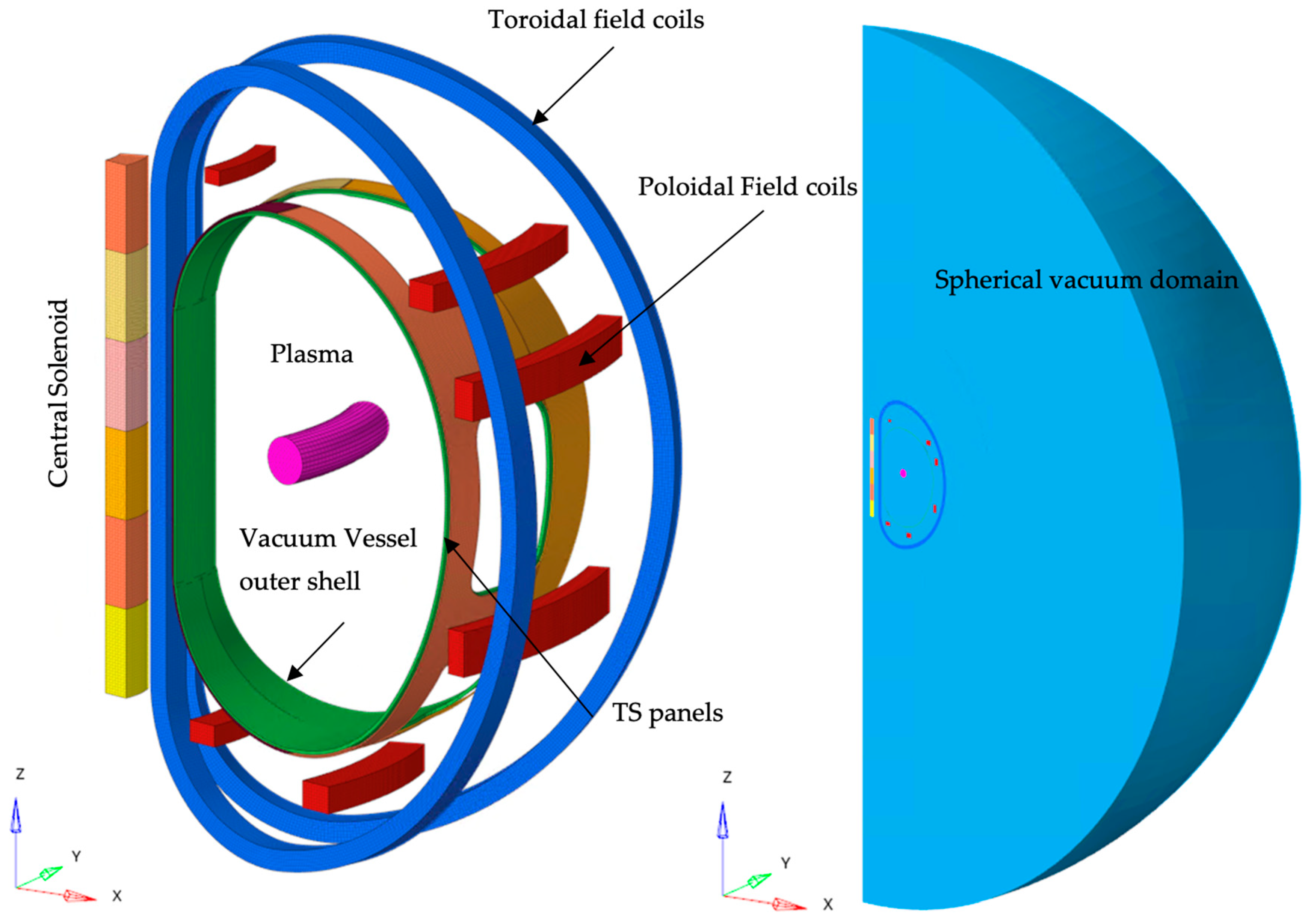
4.1. EM FE Modelling Methodology
A 30° FE model is developed, which consists of three major assemblies (
Figure 6) within a spherical vacuum domain, with a relative magnetic permeability of 1 assigned to all components.
Excitation Component: Represents the combined coils and plasma current, serving as the primary source of applied current loads.
TS Component: Corresponds to the panels. To maintain element aspect ratio integrity, an effective thickness of 0.01 m is assumed, leading to an assigned electrical resistivity of 4.8 × 10−⁸ Ω·m (with a nominal value of 4.8 × 10−⁹ Ω·m) to properly account for Lorentz force distribution.
Vacuum Vessel outer shell Component: Represents the Vacuum Vessel, which is electrically insulated from the TS panels but interacts inductively due to proximity. Its electrical resistivity is set at 7.65 × 10−⁷ Ω·m.
The finite element simulations were conducted using the ANSYS EMAG module, utilising the SOLID236 element type. A series of three-dimensional transient analyses were performed based on the magnetic vector potential formulation. In this formulation, the primary degrees of freedom are the electric potential (VOLT) and the magnetic edge-flux (AZ), where AZ corresponds to the line integrals of the magnetic vector potential along the edges of each element.
To accurately evaluate the peak Lorentz forces for subsequent structural assessments, an aluminium layer with an equivalent resistivity corresponding to a 0.01 m thickness was assumed. This simplification is justified by the observation that the thermal shield thickness is significantly smaller than the electromagnetic skin depth—ranging between 110 mm and 220 mm—under coil charge and discharge conditions at frequencies between 25 [mHz] and 100 [mHz]. For metallic sheets where the thickness “
d” is much less than the skin depth “
δ”, the induced current density can be considered nearly uniform throughout the thickness. Accordingly, the total current per unit length is obtained by integrating the current density over the sheet thickness
d:
For small
, a first-order Taylor expansion yields the following:
This last formula demonstrates that, when the thickness of the metal is smaller than the skin depth, the current is proportional to the product between the induced current density and the metal thickness. Considering a constant electromotive force (emf) defined by the relationship |emf| = RI, where “R” is the electrical resistance of the plate, and “I” is the induced current. This expression indicates that, for a constant emf, any change in resistance R must be accompanied by a corresponding change in current I to maintain the constancy of their product.
From this principle, the following considerations arise:
Equivalent emf through geometric and material adjustments: An increase in the plate thickness by a certain factor, coupled with a decrease in material resistivity by the same factor, yields the same emf magnitude. Consequently, the induced force remains unchanged. This enables the generation of thicker finite element meshes without altering the electromagnetic response.
Linear scaling of force with thickness: Given the linear dependence of the emf on thickness, the resulting electromagnetic force scales linearly and proportionally with the plate thickness. This property facilitates the rescaling of electromagnetic forces on panels of varying thicknesses, which is particularly advantageous in structural assessments.
This structured FEM approach allows for precise assessment of electromagnetic interactions, particularly Lorentz forces, which serve as critical input for thermal and structural analyses. The following loading conditions are analysed:
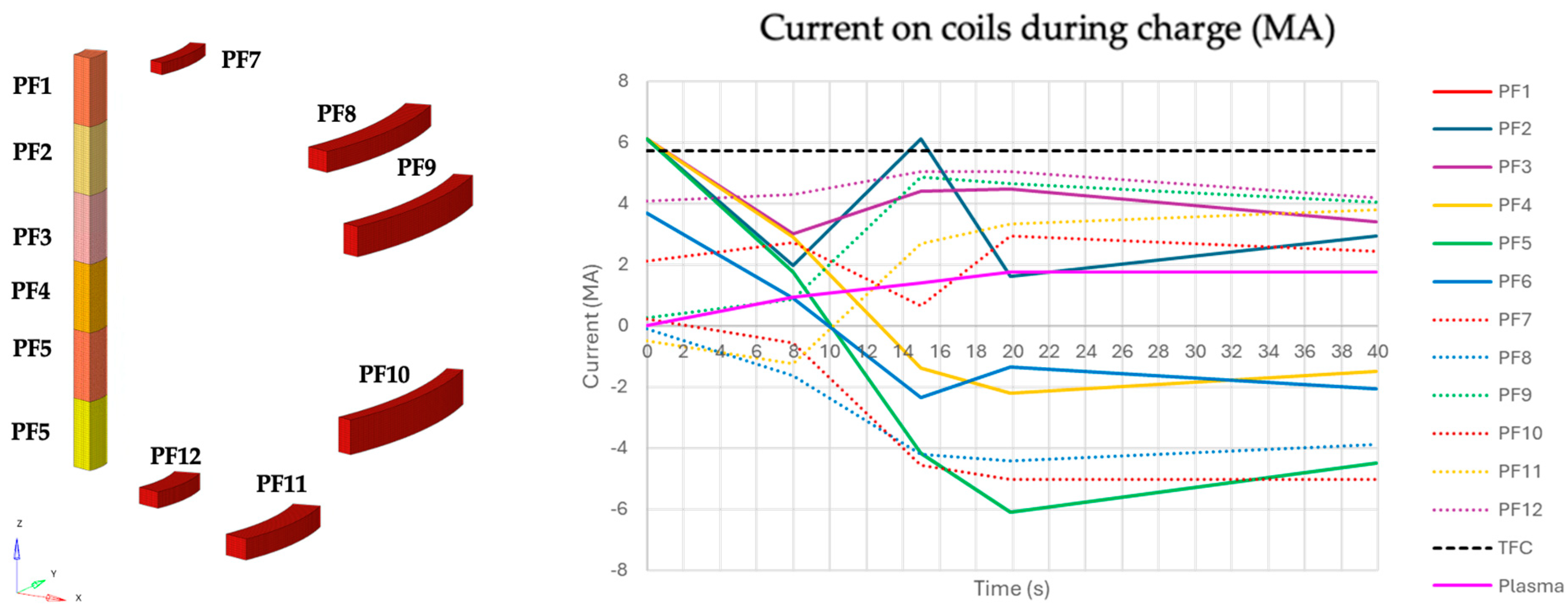
Ramping Load Condition (Charge): Poloidal Field (PF) and Central Solenoid (CS) coils, along with plasma, experience monotonically increasing current ramps until full load, while Toroidal Field (TF) coils maintain a constant current.
Discharge State (Discharge): All coils are fully discharged with no plasma present.
Figure 7 and
Figure 8 show the coils’ nomenclature (on the left) and the behaviour of coils and plasma current during charge and discharge events (on the right).
4.2. Structural FE Modelling
The entire modelling process was developed within the CAE environment of ABAQUS 2024 [
12]. The modelling assumptions and methods adopted to evaluate the structural integrity of the TS designs are explained in this section.
4.2.1. Analysis Type
A first step involves a static structural analysis that includes all mechanical loads, including self-weight and electromagnetic loads. The objective is to investigate the displacement and stress fields, and this step also serves to define the pre-stressed state for the subsequent step, which consists of a linear buckling analysis under pre-stress conditions.
The purpose of the buckling analysis is to investigate structural stability under pre-stressed conditions, accounting for the effects of self-weight and, most importantly, the electromagnetic loads.
4.2.2. Mesh
Given the geometry of the system, the panels and the reinforcements were modelled using shell-type elements described in
Table 4. In
Figure 9 and
Figure 10, the mesh developed for various design concepts is shown, respectively, for a simple panel (with and without ribs) and smaller panel designs. Details are reported in
Table 4. The mesh quality check is performed on the first model by doubling the node numbers to confirm that the variation in the results is less than 3%, once it is confirmed that the same mesh size is used in all other designs.
4.2.3. Loads
The mechanical loads acting on the thermal shield are, as expected, the gravitational load and the electromagnetic (EM) loads. The design was developed considering the deadweight and one electromagnetic (EM) event as the most critical scenario, referred to as the Discharge Event. With these loads, the optimisation process focused on defining the panel dimensions, thickness, number of supports, material properties, and the reinforcement ribs required to ensure structural integrity. To apply the EM loads on the structural model, an interpolation routine is used for transferring the EM loads to the nodes of the structural model. The interpolation routine uses a triangulation method with additional corrections to ensure the mapping has an error of less than 1%.
4.2.4. Boundary Conditions
Each support is simulated as a boundary condition applied to a single node where the three translational degrees of freedom are constrained.
4.2.5. Mechanical Properties of Materials
The mechanical properties of the materials used in this study are reported in
Table 5. Allowable stress is calculated by selecting the lower value between two-thirds of the material yield strength and one-third of its ultimate tensile strength, with the material properties evaluated at the design temperature according to the instructions of RCC-MR.
4.2.6. Static and Stability Criteria
RCC-MR rules are used to assess the structural integrity of the TS designs. The rules used for evaluating static failures are summarised in
Table 6. To perform this check, the Von-Mises stress distribution is screened using a legend with the upper limit set to 1.5 times the allowable stress, which helps us to identify overstressed zones.
According to the RCC-MR code, for linear buckling analyses under pre-stressed conditions, a load amplification factor of at least 2.5 is required to ensure adequate safety margins against instability when geometric imperfections are considered. Given that the present analyses are at the conceptual design stage, the influence of imperfections is conservatively accounted for by applying a factor of 5. As a result, the minimum load amplification factor necessary to validate the design under pre-stressed buckling conditions is set to 10.
4.3. Thermal FE Modelling Methodology
The entire modelling process was developed within the CAE environment of Abaqus. The modelling assumptions and methods adopted to evaluate the structural integrity of the TS designs are explained in this section.
4.3.1. Analysis Type
The thermal analysis methodology adopts a steady-state approach, incorporating boundary conditions that account for radiative heat exchange and localised cooling effects, such as those introduced by embedded cooling pipes. The primary objectives of the analysis are to evaluate the resulting temperature distribution within the system, to quantify the temperature gradients in the vicinity of the cooling elements when present, and to assess the heat flux entering and exiting the thermal shield.
4.3.2. Mesh
The same mesh developed for structural analysis is used. The elements are changed to DS4 elements. This element type is chosen as it best approximates the geometry of the panels given.
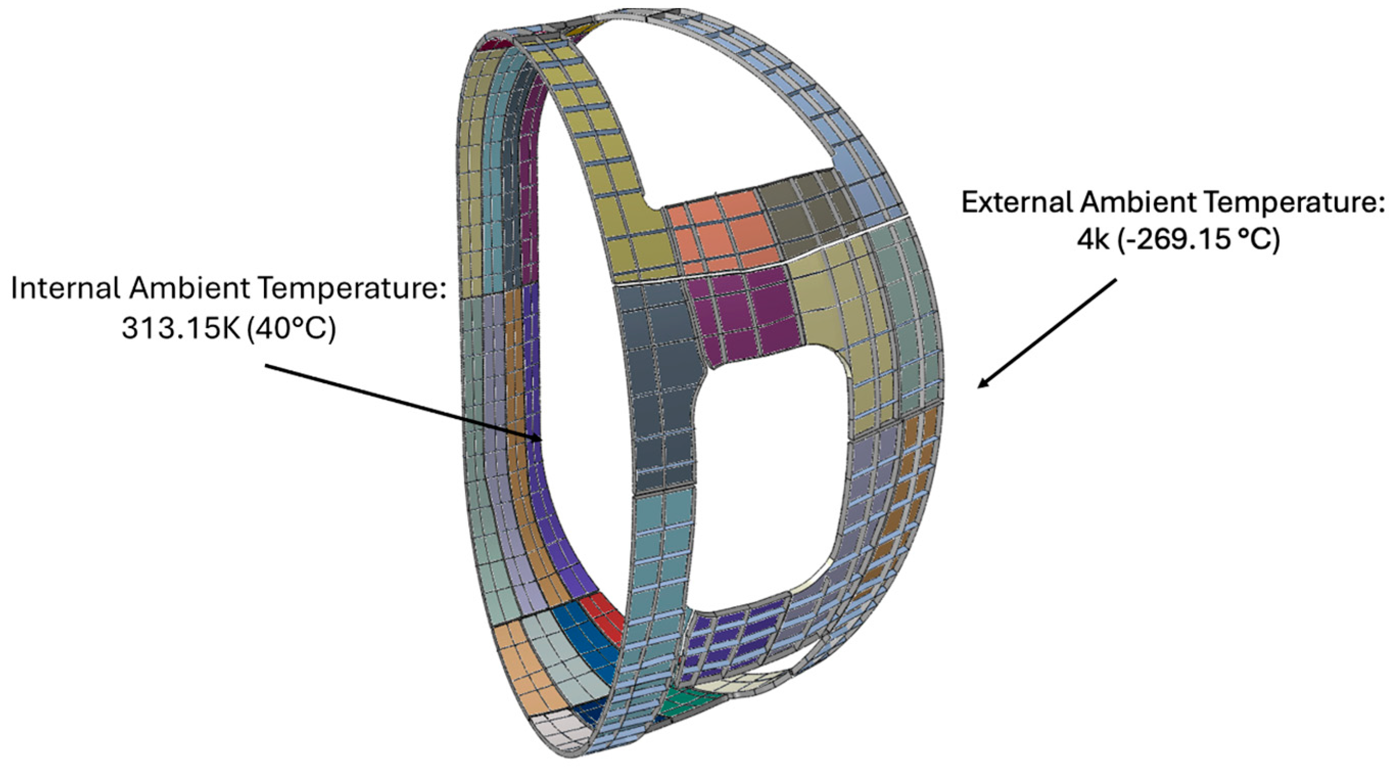
4.3.3. Loads, Interactions and Boundary Conditions
Radiation on both the internal and external surfaces was applied in this case as well; the ambient temperatures are 40 °C (313 K) for the internal side and 4 K (–269 °C) for the external side as shown in
Figure 11. The emissivity of aluminium is a critical parameter in thermal analyses. An emissivity as low as 0.01 is exceptionally rare and would only be achievable under idealised conditions, requiring an extremely polished, highly reflective, and contamination-free surface. In practice, a value of approximately 0.2 is commonly associated with well-polished aluminium surfaces that are clean and largely free from oxidation. On the other end of the spectrum, the emissivity of aluminium can reach values up to 0.9 when the surface is significantly oxidised or anodised. In such cases, the presence of an aluminium oxide layer substantially enhances the material’s ability to absorb and emit thermal radiation by decreasing its reflectivity. From a thermal management perspective, low emissivity values promote efficient thermal exchange, facilitating more uniform temperature distributions and minimising thermal gradients, particularly advantageous in configurations involving cooling channels or pipes. In contrast, high emissivity tends to increase thermal gradients due to uneven heat dissipation. For modelling purposes, an emissivity of 0.2 is adopted as a realistic and balanced reference value, avoiding overly conservative assumptions while remaining consistent with achievable surface conditions.
Cooling pipes were modelled without introducing their geometry; we modelled them with the boundary conditions applied to rows of nodes, as shown in yellow in the
Figure 12 with a fixed temperature of 80 K (–193 °C).
5. Results and Discussion
This section presents the results of the electromagnetic, structural, and thermal analyses for various studied configurations. For the electromagnetic analysis, the total forces acting on the panels under the most critical loading scenario are reported, along with plots of the induced current density. In the structural analysis, stress distributions are provided. The stress plots include a defined maximum stress value in the legend, above which the regions are displayed in grey to indicate areas of potential failure. Additionally, the load factors obtained from the buckling analyses are reported to assess structural stability. For the thermal analysis, the temperature distribution resulting from the applied thermal loads is shown. The results are evaluated by investigating the temperature distribution, with particular attention to the presence and magnitude of thermal gradients.
5.1. Simple Panel Design
5.1.1. Electromagnetic FE Model and Results
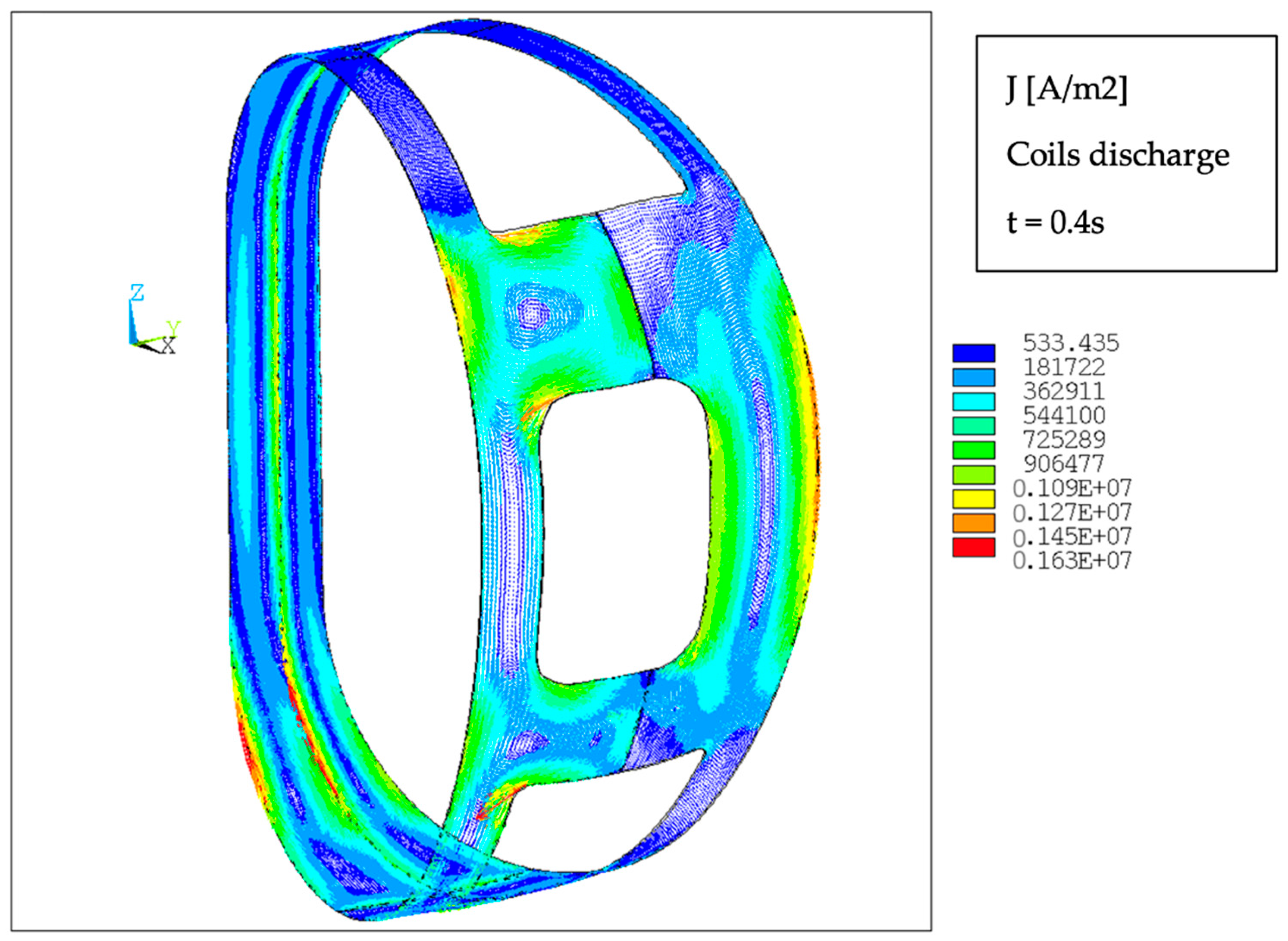
For this configuration, the coil charge and discharge are studied since it is the most demanding. Here, the results of discharge are reported; the total force and moment, in the global coordinate system, are shown in
Table 7 for the most demanding time instant. The behaviour of the induced current is shown in
Figure 13. On each panel, a current loop is generated due to the magnetic field variation orthogonal to the panel surface.
5.1.2. Structural FE Model and Results
The first parameter investigated was the aluminium panel thickness. Various thicknesses ranging from 1 mm to several tens of millimetres were analysed. However, a structurally stable and reliable configuration could not be achieved within this design framework. This limitation arises from the volumetric nature of electromagnetic (EM) loads. As panel thickness increases, the volume—and hence the total EM force—increases proportionally. Attempts to improve structural integrity or buckling resistance by simply increasing thickness result in greater EM loading, which, in turn, exacerbates the structural challenges. Despite extensive iterations, a thickness of 100 mm yielded the best performance in terms of structural strength and buckling resistance. Nonetheless, this value is clearly impractical, as it significantly exceeds feasible manufacturing and integration limits. A realistic thickness is identified in the range of from 4 mm to 5 mm. However, designs within this feasible range failed to meet the structural requirements: neither buckling stability nor stress distribution satisfied the necessary criteria to ensure the thermal shield’s performance and reliability. These findings highlight the difficulty of achieving a viable structural design using thin aluminium panels when subjected to volumetric electromagnetic loads.
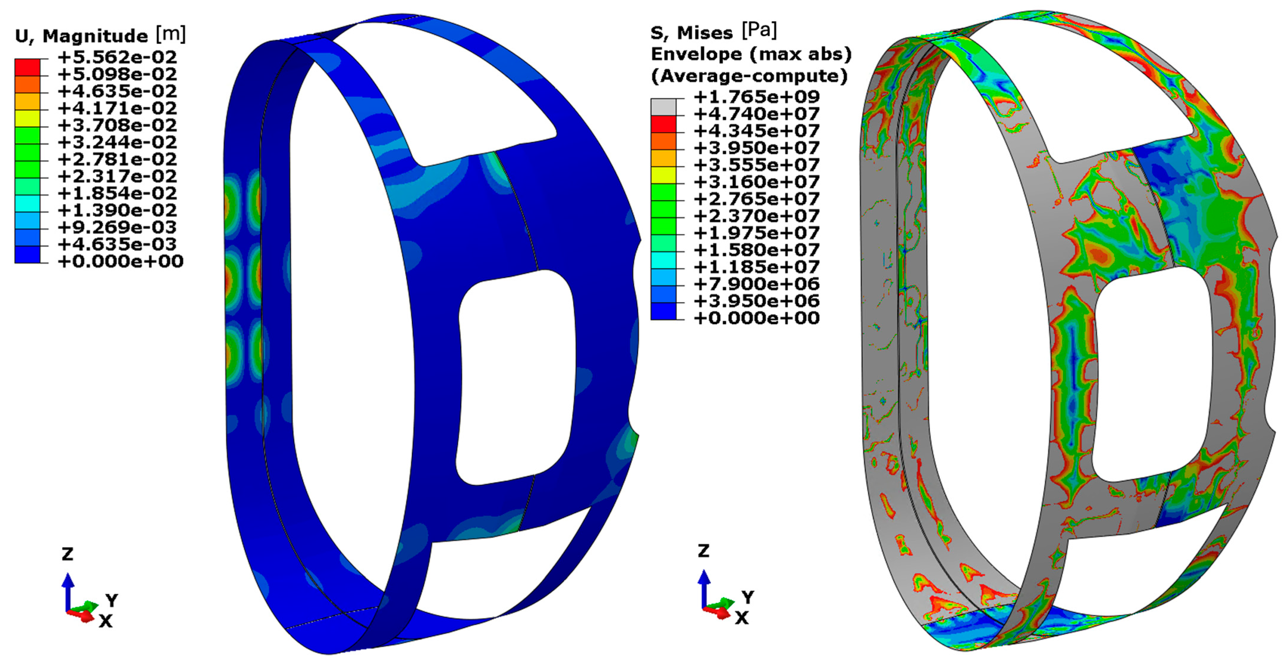
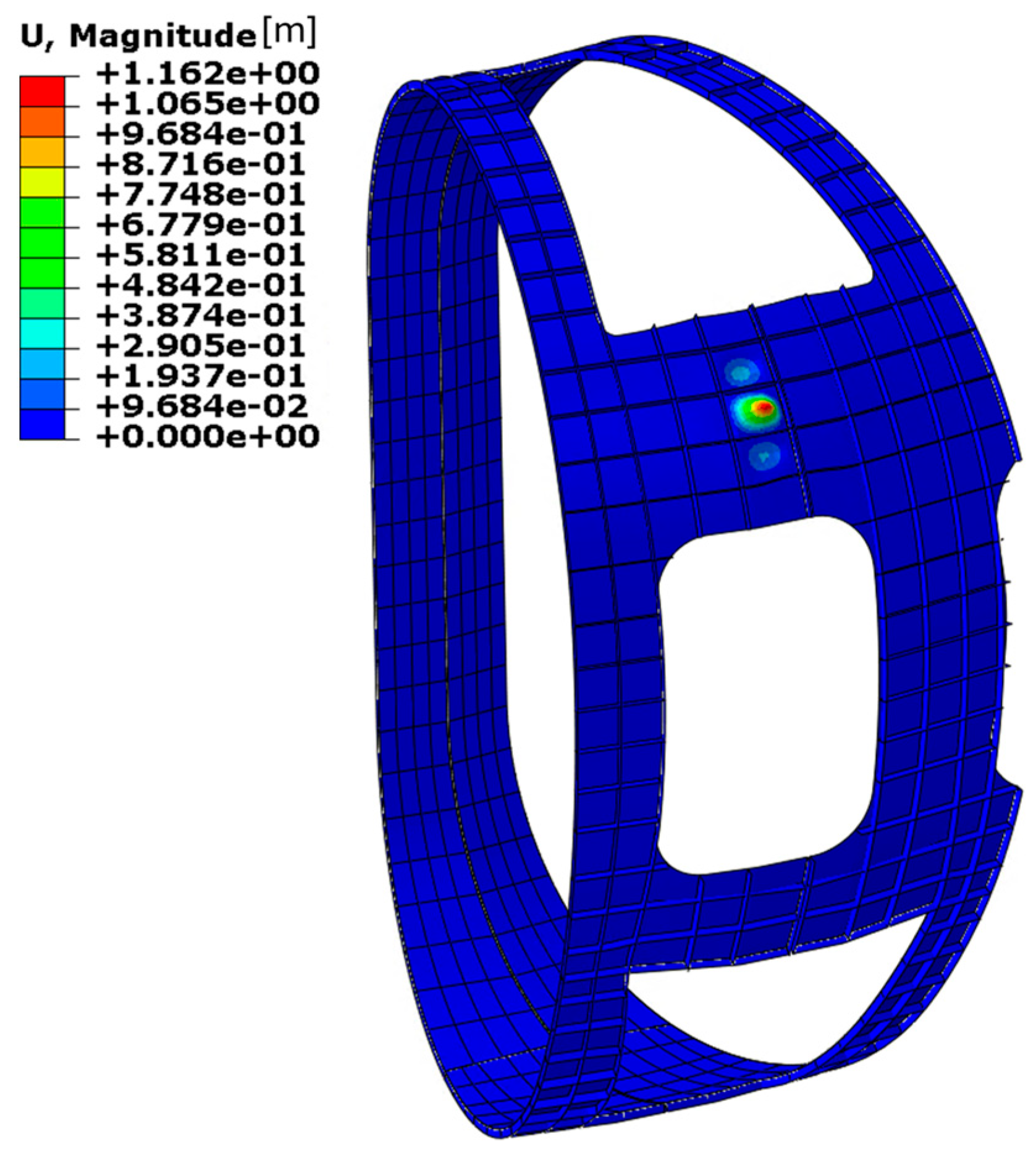
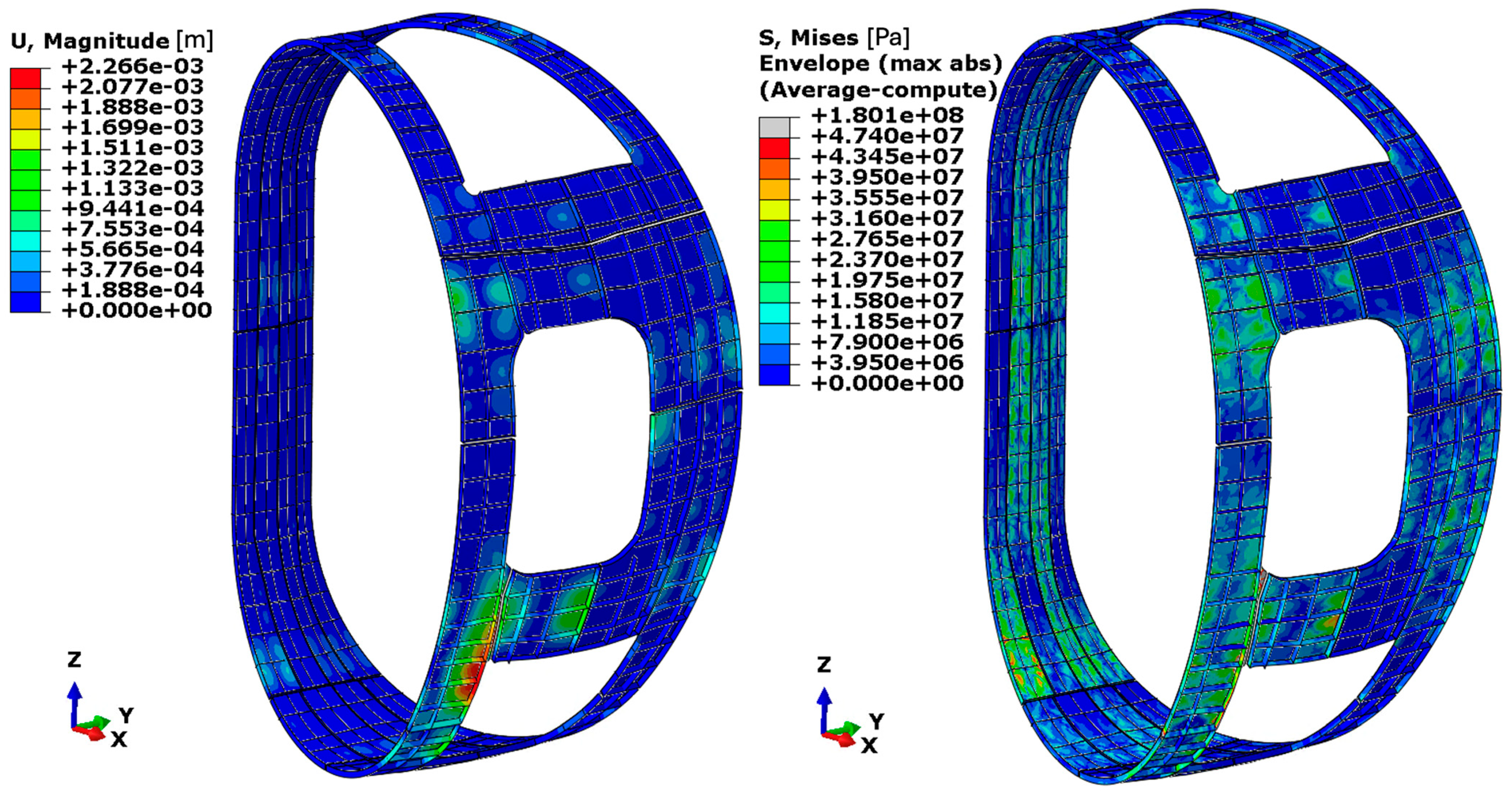
The results are presented in terms of displacement fields and Von Mises equivalent stress distributions (
Figure 14) for panels with a thickness of 5 mm. In the stress plots, the colour scale is defined such that the zones in grey correspond to zones where the stress exceeds the allowable stress limit for aluminium alloy 1100. Since the analysis is conducted using a shell model, the stress distributions represent the envelope between the inner and outer surfaces of the shell elements. This approach captures both membrane and bending contributions, providing a comprehensive view of the stress state across the panel thickness.
Due to the inability to achieve a structurally feasible design using aluminium alloy 1100, an alternative material—aluminium alloy 7075—was evaluated. Although this alloy possesses significantly higher mechanical strength, it still falls short of meeting the structural integrity requirements under the given loading conditions. Based on its mechanical properties, the minimum required panel thickness for aluminium 7075 to ensure structural adequacy is reduced from 100 mm to approximately 40 mm. Nonetheless, this thickness remains impractical, exceeding the acceptable design limit by roughly an order of magnitude. In
Figure 15, the Von Mises equivalent stress distribution for panels with a thickness of 5 mm is presented, with the stress scale calibrated such that the grey zones correspond to the zones where the stress exceeds the allowable stress limit for aluminium 7075. The summary of all iterations is presented in
Table 8. These findings lead to the conclusion that the configuration referred to as the
Simple Panel does not provide satisfactory structural performance when panel thicknesses are limited to the 4 mm–5 mm range. As a result, it becomes necessary to incorporate additional structural features—such as reinforcing ribs—to improve both the load-bearing capacity and buckling resistance of the thermal shield panels. This rationale forms the basis for the development of an alternative design configuration, herein referred to as the
Reinforced Panel with Ribs design.
5.1.3. Thermal FE Model and Results
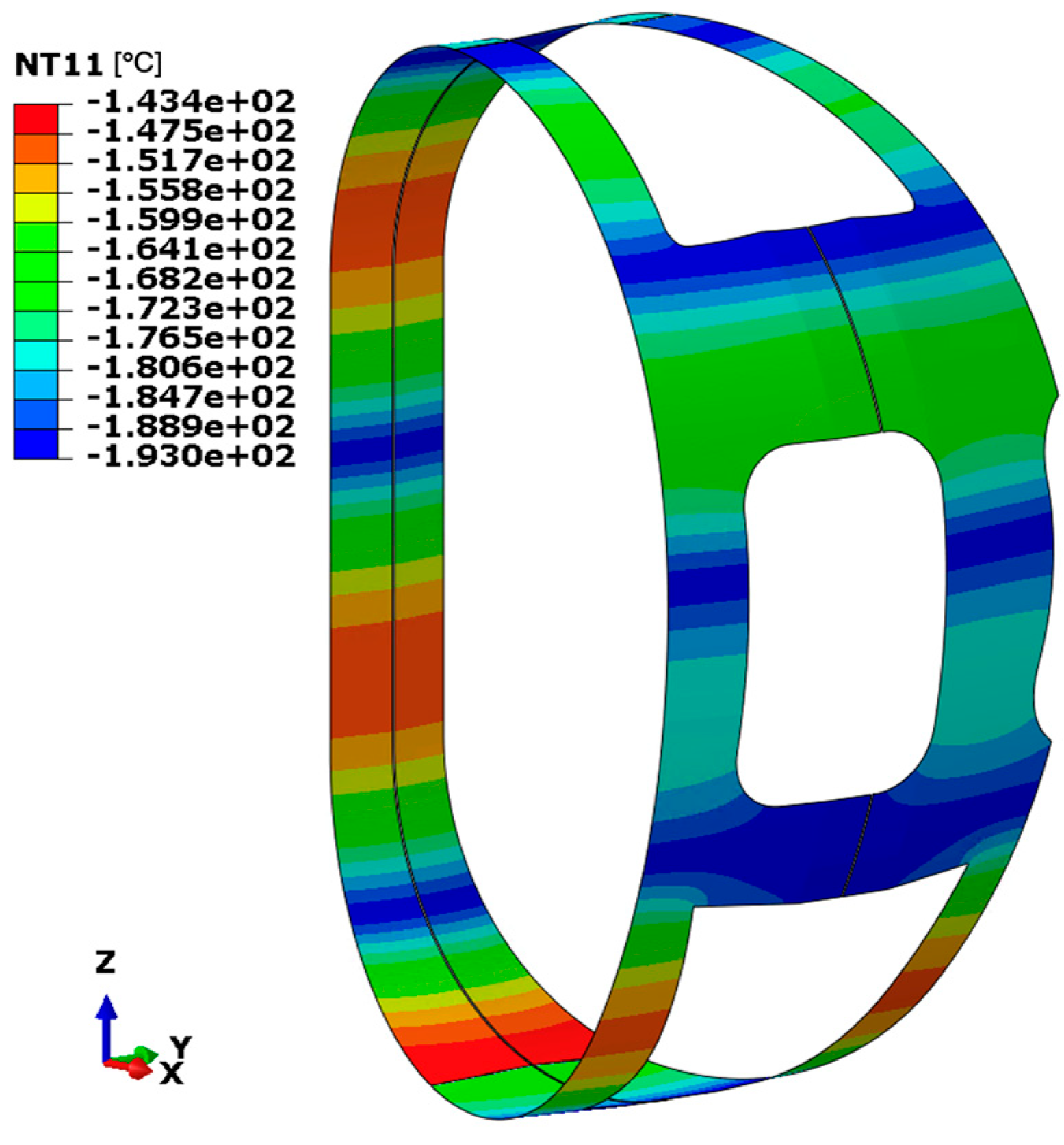
The temperature distribution illustrated in
Figure 16 reveals significant gradients near the regions where boundary conditions, modelled as imposed temperatures, simulate the presence of cooling pipes. The minimum temperature stabilises at approximately –193 °C (around 80 K), as dictated by the applied boundary condition, while the maximum temperature reaches approximately –143.4 °C (around 130 K) in areas distant from the influence of the cooling system. Despite the presence of thermal gradients, the overall temperature distribution within the thermal shield remains within acceptable limits. This performance is primarily attributed to the high thermal conductivity of aluminium, which facilitates efficient temperature equalisation throughout the structure.
5.2. Reinforcement with Ribs Design
5.2.1. Electromagnetic FE Model and Results
As the panel dimensions and their connection interfaces remain unchanged, the same electromagnetic volumetric forces computed for the simple panel concept are applied to this configuration as well.
5.2.2. Structural FE Model and Results
First Iteration: Following the introduction of vertical stiffening ribs, the minimum required panel thickness was assessed by incrementally increasing the thickness from 1 mm up to 4 mm. At a thickness of 4 mm, the maximum displacement stabilises at approximately 10 mm, while the overall distribution of Von Mises equivalent stress remains well below the allowable limit for aluminium alloy 7075, as illustrated in
Figure 17. This threshold is indicated in the stress plots by the grey colour in the legend. Despite the favourable stress distribution, the corresponding load amplification factor is approximately 3, which is insufficient to ensure an adequate safety margin. As a result, this configuration is deemed unsuitable from a buckling resistance perspective.
Second Iteration: To enhance the structural performance, an additional set of transverse reinforcing ribs was introduced, complementing the existing longitudinal reinforcements. This modification aimed to achieve a buckling-resistant design while maintaining minimal panel thickness. As in previous iterations, the panel thickness was varied from 1 mm to a maximum of 4 mm. At a thickness of 4 mm, the structural response is satisfactory with respect to stress distribution. No localised stress concentrations were observed that might compromise the integrity of the aluminium 7075 material. The maximum displacement recorded is approximately 5.6 mm, and the Von Mises equivalent stress remains well below the allowable limit as plotted in
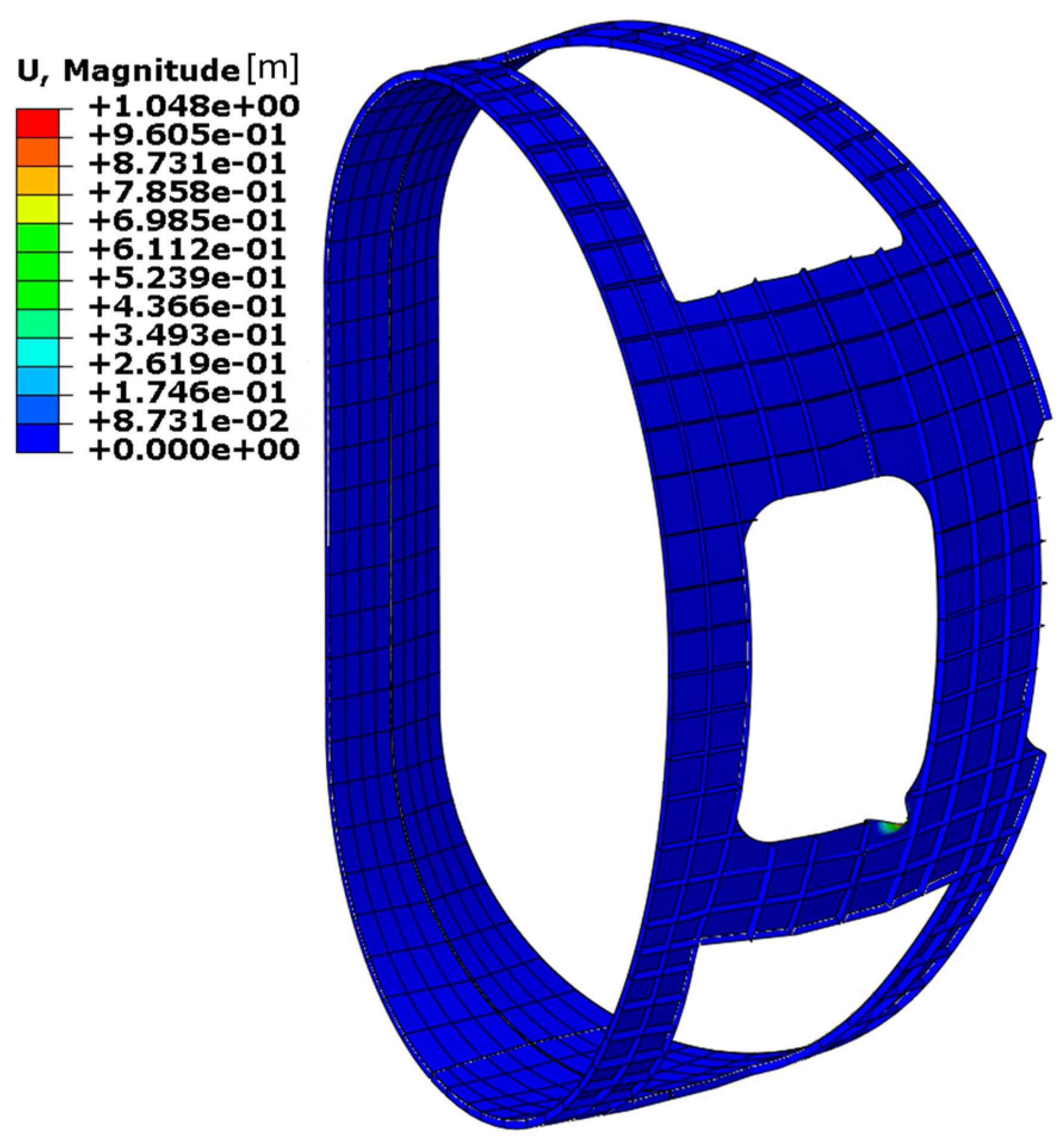
Figure 18. However, despite the addition of transverse reinforcements, the structure still exhibits instability (shown in
Figure 19) under electromagnetic loads associated with the discharge scenario, with an amplification factor of 4.66. Thus, while the design is acceptable in terms of strength, it remains inadequate from the perspective of buckling resistance.
Third iteration: An attempt was made to improve buckling stability by progressively increasing the number of supports until a stable configuration was achieved. The structural response is satisfactory with respect to stress distribution as shown in
Figure 20. The buckling (shown in
Figure 21) analysis under prestressed conditions resulted in a load amplification factor of 27, which is considered sufficient to meet structural requirements. However, attaining this level of stability required the implementation of 587 supports, more than twice the number used in previous configurations. The summary of the results for reinforced design is presented in
Table 9. As with the
Simple Panel design, this approach presents significant feasibility challenges. The required number of supports is unrealistic from a manufacturing and integration standpoint. Consequently, this second design iteration is also deemed unviable. This outcome led to the conclusion that a fundamental geometric redesign is necessary to reduce the generation of electromagnetic loads and achieve a feasible and structurally stable solution.
5.2.3. Thermal FE Model and Results
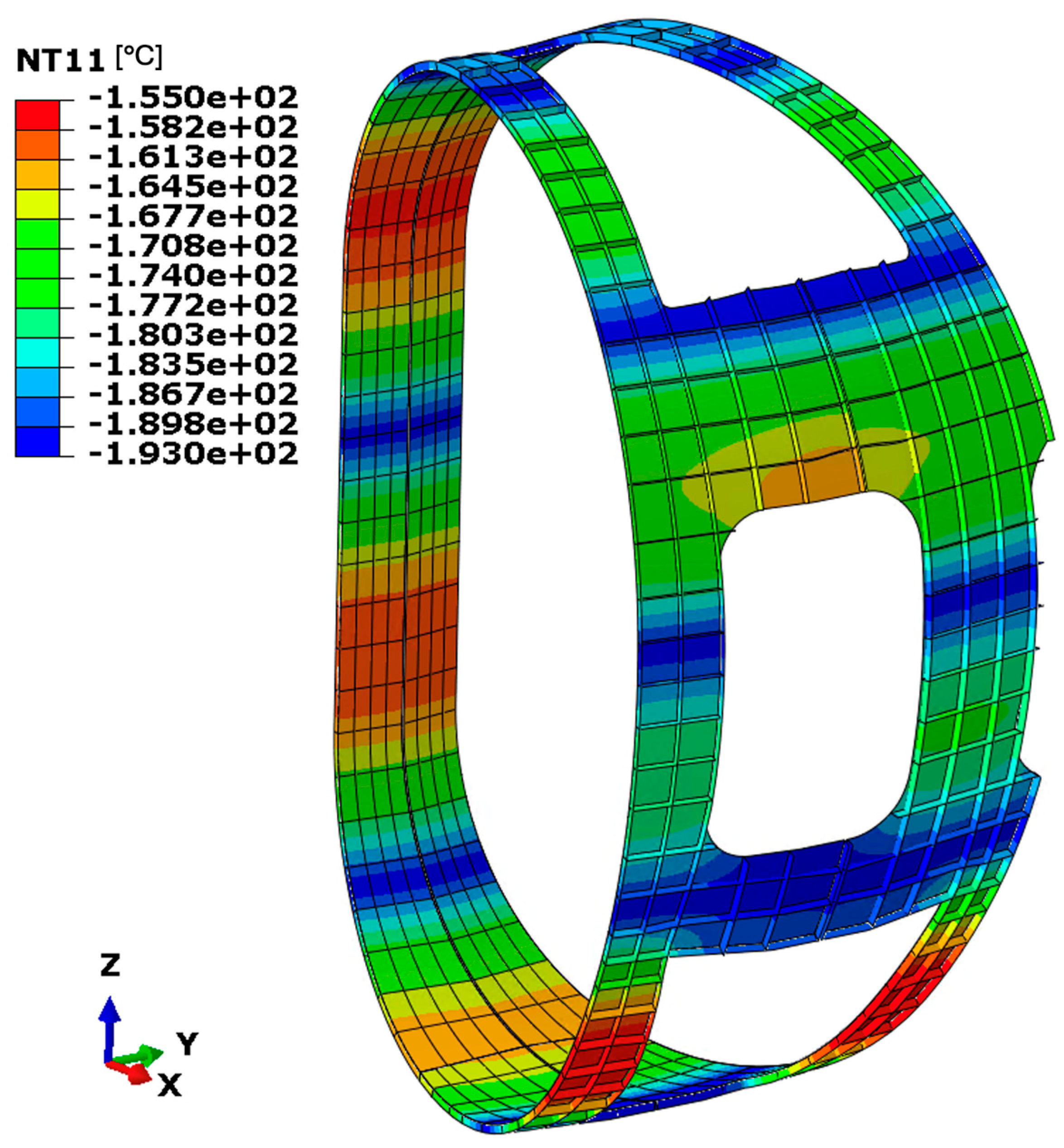
The maximum temperature stabilises around –155 °C (approximately 118 K), while the minimum value, as expected near the cooling pipes, is 80 K (approximately –193 °C) as shown in
Figure 22. Temperature gradients are observed between adjacent cooling pipes. Also in this scenario, thanks to the good thermal conductivity of aluminium, the temperature distribution is acceptable, with limited thermal gradients.
5.3. Smaller Panel Design
5.3.1. Electromagnetic FE Model and Results
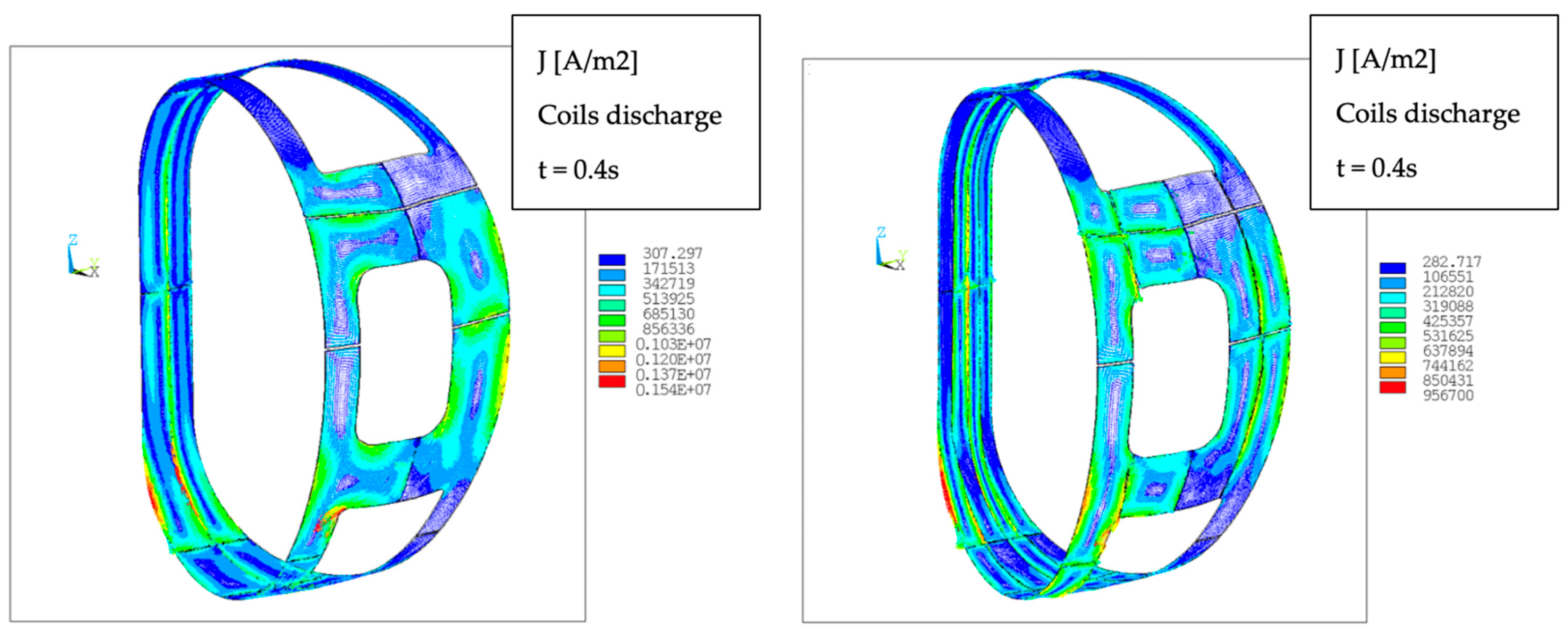
The electromagnetic analysis was repeated following the introduction of strategic cuts in both the toroidal and poloidal directions of the thermal shield. These modifications were designed to disrupt the formation of closed-loop current paths within each panel, thereby mitigating the induced EM loads. By reducing the effective surface area exposed perpendicular to the time-varying magnetic flux, the induced electromotive force (emf) is diminished, which, in turn, leads to a corresponding decrease in induced currents and Lorentz forces.
The first intervention consisted of a toroidal cut (corresponding to iterations 1 and 2), as illustrated in
Figure 5. This alteration effectively interrupted current circulation paths, resulting in a significant reduction in EM loads as shown in
Figure 23. Subsequently, a vertical was introduced, as shown in which further attenuated the EM loads (corresponding to iteration 3). The outcomes associated with this final configuration are summarised in
Table 10 and
Table 11. As observed, the main component of the volume forces generated by the electromagnetic loads is in the X direction, resulting in a reduction of 40% in the discharge event.
5.3.2. Structural FE Model and Results
First Iteration: In this configuration, the panel thickness was set to 4 mm, and an initial design lacking reinforcements was evaluated while maintaining a practical number of supports. A total of 151 supports were employed, as illustrated in
Figure 5. Nonetheless, the resulting stress distribution reveals that the structural performance is unsatisfactory. Even with the use of a high-strength aluminium alloy from the 7000 series, extensive areas of the panel exceed this threshold, as shown in
Figure 24. These findings highlight that, despite significant reductions in electromagnetic loads achieved through earlier design changes, unreinforced panels with a 4 mm thickness remain structurally insufficient. Consequently, the addition of reinforcing ribs, as previously adopted in earlier design stages, is, again, essential to ensure structural integrity.
First Iteration: The updated design features smaller panels of iteration 1 reinforced with ribs and structural supports. The panel thickness is set to 4 mm. The results presented in
Figure 25 show that the maximum displacement is approximately 4.3 mm, and the stress distribution remains within permissible limits, even when using the lower-grade aluminium alloy 1100. In the equivalent stress plot, a grey colour marks the zone with stress higher than the allowable stress of aluminium alloy 1100, showing that the material stays safely within its operational range under the current loading conditions. However, the primary drawback of this setup is its limited buckling stability. The calculated load amplification factor is 3.3, which falls significantly short of the safety margin necessary for structural dependability. Therefore, further design optimisation is required, particularly through the subdivision of panels into smaller sub-panels, to reduce electromagnetic forces and improve buckling resistance.
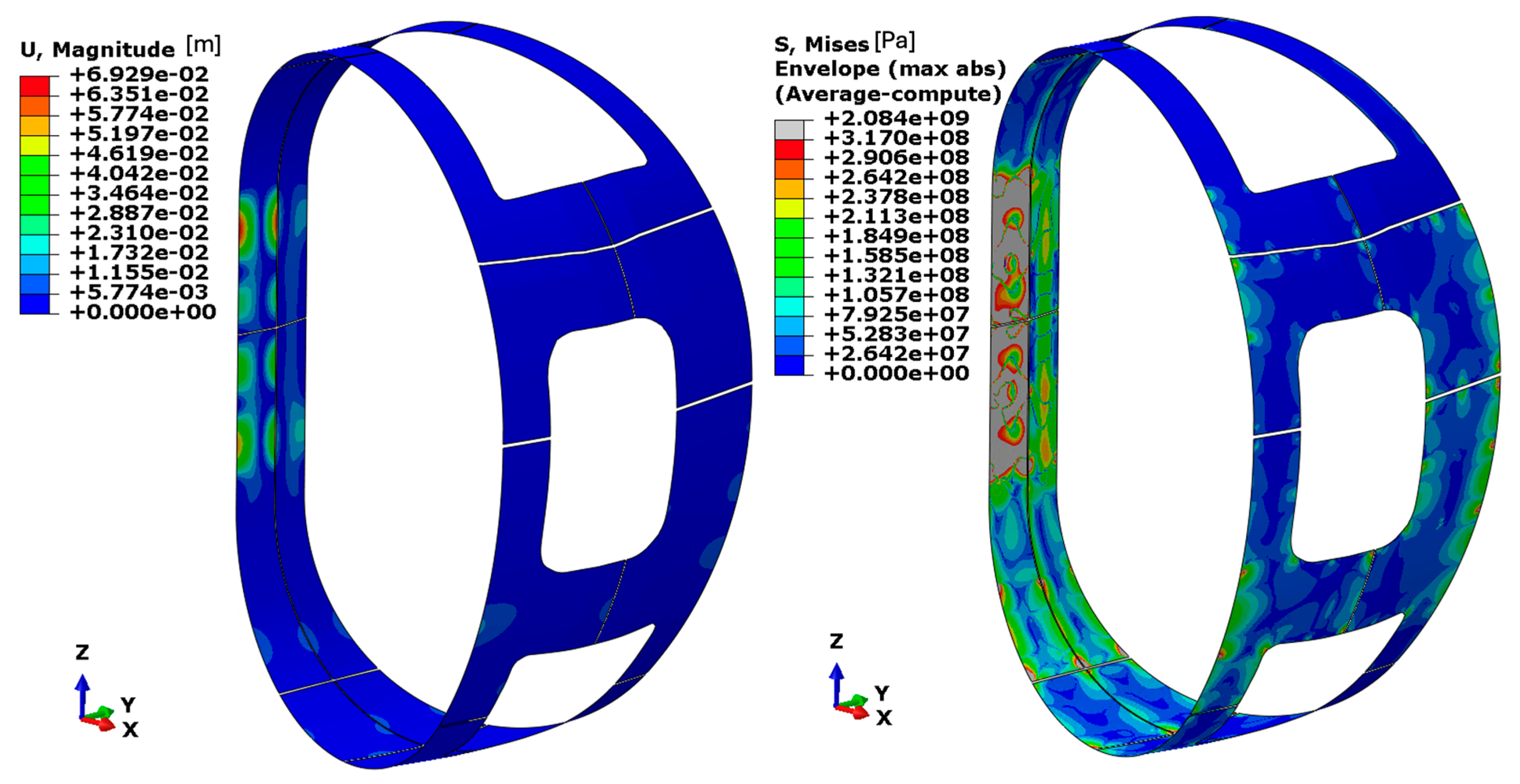
Third iteration: In this step, the geometry is further refined by increasing the subdivision of the panels by the introduction of vertical cuts. This configuration features reinforcement ribs and a panel thickness of 4 mm. The results show a maximum displacement of approximately 2.3 mm, and the stress distribution remains within acceptable limits for both aluminium 7075 and 1100, as plotted in
Figure 26. In the equivalent stress plot, a grey colour marks the zone with stress higher than the allowable stress of aluminium alloy 1100, showing that the material stays safely within its operational range under the current loading conditions. A buckling analysis, accounting for both electromagnetic and gravitational loads, reveals a load amplification factor of approximately 12, indicating a significantly improved stability margin. The summary of results is presented in
Table 12.
In
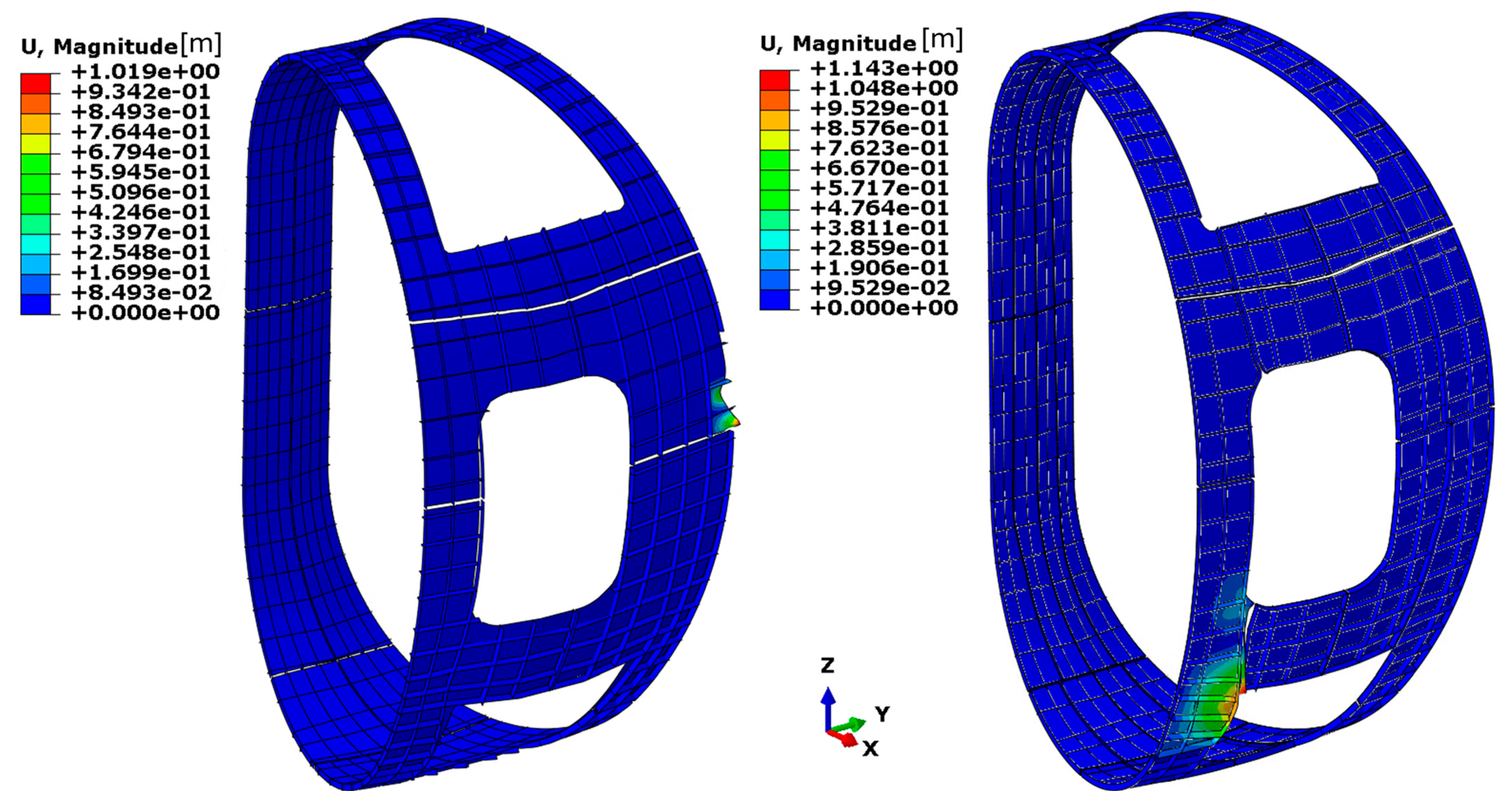
Figure 27, the buckling results for the second and third iterations of the smaller panel design are presented.
5.3.3. Thermal FE Model and Results
The maximum temperature stabilises around –9.16 °C (approximately 263 K), while the minimum value, as expected near the cooling pipes, is 80 K (approximately –193 °C) as shown in
Figure 28.
The maximum temperature value is localised in one of the regions farthest from the cooling pipe. This results in a significant temperature gradient, and that area tends to reach a thermal equilibrium governed by both the internal and external radiative exchanges. The corresponding equilibrium temperature is approximately –10 °C.
6. Summary and Conclusions
This study presents a comprehensive, multidisciplinary approach to the design and optimisation of the TS for the VNS tokamak. Due to the unique environment in the VNS—including intense magnetic fields, neutron flux, and cryogenic operating temperatures—an effective thermal shield must balance stringent requirements for thermal insulation, electromagnetic load mitigation, and structural stability. Three main design configurations were developed and analysed:
Simple Panel Design using aluminium (Al-1100 and Al-7075);
Reinforced Panel Design with Ribs;
Smaller Panel Design with Strategic Cuts and Ribs.
A systematic Finite Element Method (FEM) workflow was implemented using ANSYS EMAG 2024 for electromagnetic analysis and ABAQUS 2024 for structural and thermal assessments. Each configuration underwent multiple iterations, evaluating panel thickness, material properties, support schemes, reinforcement geometries, and electromagnetic force response due to coil discharge events. Initial results showed that while aluminium offered favourable thermal conductivity, its high electrical conductivity led to severe electromagnetic loading. Reinforcing the panels with ribs improved stress distribution, but buckling stability remained a challenge. A configuration employing smaller subdivided panels with both vertical and toroidal cuts succeeded in reducing induced currents and electromagnetic forces, offering a balance between structural and thermal performance.
Key conclusions include:
Aluminium’s Limitations: Despite its excellent thermal conductivity, aluminium—especially in unreinforced form—cannot meet the structural demands due to excessive electromagnetic forces. Even high-strength variants such as Al-7075 require impractical thicknesses to maintain structural integrity.
Importance of Reinforcements: Introducing structural ribs significantly improves stress management and reduces displacement. However, without addressing electromagnetic load origins, even reinforced configurations face buckling limitations unless supported by an unfeasible number of mechanical supports.
Electromagnetic Load Mitigation: Segmenting panels and introducing poloidal and toroidal cuts proved highly effective in reducing closed-loop currents and their associated forces. This design evolution allowed for lower stresses and improved stability, even at feasible thicknesses and support counts.
Thermal Viability: Across all configurations, the high thermal conductivity of aluminium contributed to acceptable thermal gradients. Nevertheless, thermal performance must be balanced with structural constraints in future designs.
Future Directions: The design process is currently underway, with ongoing research dedicated to exploring alternative solutions to optimise the Thermal Shield’s performance and manufacturability. Key areas of investigation include:
Composite Panel Structures: These may provide superior thermal insulation while minimising eddy current generation, offering potential improvements over conventional designs.
Passive Cooling Techniques: The adoption of passive cooling methods could streamline the thermal management system, reducing complexity and enhancing reliability.
Furthermore, the analysis is being expanded to assess Vertical Displacement Events (VDEs), a critical category of off-normal operational scenarios that pose significant electromagnetic and mechanical challenges. To validate the structural resilience of proposed designs under extreme conditions. By addressing these aspects, the ongoing efforts seek to refine the Thermal Shield design, ensuring its effectiveness and feasibility for fusion applications.
Author Contributions
Conceptualization, F.V., I.P., G.F., I.M., L.G., C.L., and F.L.,; methodology, F.V. and L.G.; software, S.T., P.H., G.F., and I.P.; resources, F.L.; writing—original draft preparation, F.V., S.T., P.H., and I.P.; writing—review and editing, P.H.; visualization, S.T., P.H., and I.P.; supervision, F.V. and L.G., project administration, F.V., C.L., L.G., and F.L.; funding acquisition, F.L. All authors have read and agreed to the published version of the manuscript.
Funding
This research was funded by EUROfusion (Project 101052200).
Data Availability Statement
The original contributions presented in this study are included in the article; further inquiries can be directed to the corresponding author.
Conflicts of Interest
Authors Fabio Viganò, Irene Pagani, Simone Talloni, Pouya Haghdoust, Giovanni Falcitelli and Flavio Lucca were employed by the LTCalcoli S.r.l. The remaining authors declare that the research was conducted in the absence of any commercial or financial relationships that could be construed as a potential conflict of interest.
References
- Aymar, R.; Barabaschi, P.; Shimomura, Y. The ITER design. Plasma Phys. Control. Fusion 2002, 44, 519. [Google Scholar] [CrossRef]
- El-Guebaly, L.A. Fifty Years of Magnetic Fusion Research (1958–2008): Brief Historical Overview and Discussion of Future Trends. Energies 2010, 3, 1067–1086. [Google Scholar] [CrossRef]
- Królas, W.; Ibarra, A.; Arbeiter, F.; Arranz, F.; Bernardi, D.; Cappelli, M.; Castellanos, J.; Dézsi, T.; Dzitko, H.; Favuzza, P.; et al. The IFMIF-DONES fusion oriented neutron source: Evolution of the design. Nucl. Fusion 2021, 61, 125002. [Google Scholar] [CrossRef]
- Federici, G. Testing needs for the development and qualification of a breeding blanket for DEMO. Nucl. Fusion 2023, 63, 125002. [Google Scholar] [CrossRef]
- Abdou, M.A. A volumetric neutron source for fusion nuclear technology testing and development. Fusion Eng. Des. 1995, 27, 111–153. [Google Scholar] [CrossRef]
- Abdou, M.A.; Berk, S.E.; Ying, A.; Martin Peng, Y.K.; Sharafat, S.; Galambos, J.D.; Hollenberg, G.W.; Malang, S.; Proust, E.; Booth, S.J.; et al. Results of an international study on a high-volume plasma-based neutron source for fusion blanket development. Fusion Technol. 1996, 29, 1–57. [Google Scholar] [CrossRef]
- Bachmann, C.; Siccinio, M.; Acampora, E.; Aiello, G.; Bajari, J.; Boscary, J.; Bruschi, A.; Claps, V.; Cufar, A.; Elbez-Uzan, J.; et al. Engineering concept of the VNS-a beam-driven tokamak for component testing. Fusion Eng. Des. 2025, 211, 114796. [Google Scholar] [CrossRef]
- Noh, C.H.; Nam, K.; Kwon Kang, D.; Kang, K.O.; Chung, W.; Ahn, H.J.; Her, N.I.; Yu, J.; Hamlyn-Harris, C.; Utin, Y.; et al. Final design of ITER vacuum vessel thermal shield. Fusion Eng. Des. 2013, 88, 1896–1899. [Google Scholar] [CrossRef]
- Nam, K.; Her, N.; Hur, J.; Park, W.W.; Kang, K.O.; Lim, K.; Kim, I.J.; Kang, Y.; Arzoumanian, T.; Panchal, M.; et al. Manufacturing study of lower cryostat thermal shield cylinder component for ITER tokamak. Fusion Eng. Des. 2019, 146, 1171–1175. [Google Scholar] [CrossRef]
- Koncar, B.; Garrido, O.C.; Draksler, M.; Brown, R.; Bachmann, C. Development of DEMO thermal shield concept: Design requirements and initial design. In Proceedings of the International Conference Nuclear Energy for New Europe, Bled, Slovenia, 11–14 September 2017. [Google Scholar]
- Khokhlov, M.; Bykov, V.; Lorenz, A.; Nagel, M.; Falcitelli, G.; Haghdoust, P.; Lucca, F. W7-X Magnet System Thermal Insulation Analysis Under Fast Plasma Decay Conditions. IEEE Trans. Appl. Superconductivity 2024, 34, 4207105. [Google Scholar] [CrossRef]
- ABAQUS/Standard User's Manual, Version 2024. Dassault Systèmes Simulia Corp.: Providence, RI, USA, 2024.
Figure 1.
Simple panel design and location of supports (shown in red dots).
Figure 1.
Simple panel design and location of supports (shown in red dots).
Figure 2.
Panel + rib design; first iteration.
Figure 2.
Panel + rib design; first iteration.
Figure 3.
Panel + rib design; second iteration.
Figure 3.
Panel + rib design; second iteration.
Figure 4.
Panel + rib design; support locations for each iteration (shown in red dots).
Figure 4.
Panel + rib design; support locations for each iteration (shown in red dots).
Figure 5.
Smaller panel design and location of supports (shown in red dots).
Figure 5.
Smaller panel design and location of supports (shown in red dots).
Figure 7.
Coil nomenclature (left) and coil charge current used in FE analysis (right).
Figure 7.
Coil nomenclature (left) and coil charge current used in FE analysis (right).
Figure 8.
Coil nomenclature (left) and coil discharge current used in FE analysis (right).
Figure 8.
Coil nomenclature (left) and coil discharge current used in FE analysis (right).
Figure 9.
Simple panel design mesh.
Figure 9.
Simple panel design mesh.
Figure 10.
Smaller panel design mesh: 16 panels (left) and 32 panels (right).
Figure 10.
Smaller panel design mesh: 16 panels (left) and 32 panels (right).
Figure 11.
Thermal conditions for the FE model.
Figure 11.
Thermal conditions for the FE model.
Figure 12.
Cooling pipes modelled as boundary conditions (shown by yellow circles).
Figure 12.
Cooling pipes modelled as boundary conditions (shown by yellow circles).
Figure 13.
Current density distribution on panels during coil discharge (at 0.4 s).
Figure 13.
Current density distribution on panels during coil discharge (at 0.4 s).
Figure 14.
Simple panel design: displacement (left) and equivalent stress distribution (right).
Figure 14.
Simple panel design: displacement (left) and equivalent stress distribution (right).
Figure 15.
Simple panel design: equivalent stress distribution (MPa) considering aluminium class 7075.
Figure 15.
Simple panel design: equivalent stress distribution (MPa) considering aluminium class 7075.
Figure 16.
Simple panel design: obtained temperature distribution.
Figure 16.
Simple panel design: obtained temperature distribution.
Figure 17.
Reinforced panel design, first iteration: displacement (left) and equivalent stress distribution (right).
Figure 17.
Reinforced panel design, first iteration: displacement (left) and equivalent stress distribution (right).
Figure 18.
Reinforced panel design, second iteration: displacement (left) and equivalent stress distribution (right).
Figure 18.
Reinforced panel design, second iteration: displacement (left) and equivalent stress distribution (right).
Figure 19.
Reinforced panel design, second iteration: buckling results (scale result 0.1).
Figure 19.
Reinforced panel design, second iteration: buckling results (scale result 0.1).
Figure 20.
Reinforced panel design, third iteration: displacement (left) and equivalent stress distribution (right).
Figure 20.
Reinforced panel design, third iteration: displacement (left) and equivalent stress distribution (right).
Figure 21.
Reinforced panel design, third iteration: buckling results (scale result 0.1).
Figure 21.
Reinforced panel design, third iteration: buckling results (scale result 0.1).
Figure 22.
Reinforced panel design, third iteration: obtained temperature distribution.
Figure 22.
Reinforced panel design, third iteration: obtained temperature distribution.
Figure 23.
Current density distribution in discharge at 0.4 s. (Left) Panels with toroidal cuts, (Right) panels with vertical and toroidal cuts.
Figure 23.
Current density distribution in discharge at 0.4 s. (Left) Panels with toroidal cuts, (Right) panels with vertical and toroidal cuts.
Figure 24.
Smaller panel design, first iteration: displacement (left) and equivalent stress distribution (right).
Figure 24.
Smaller panel design, first iteration: displacement (left) and equivalent stress distribution (right).
Figure 25.
Smaller panel design, second iteration: displacement (left) and equivalent stress distribution (right).
Figure 25.
Smaller panel design, second iteration: displacement (left) and equivalent stress distribution (right).
Figure 26.
Smaller panel design, third iteration: displacement (left) and equivalent stress distribution (right).
Figure 26.
Smaller panel design, third iteration: displacement (left) and equivalent stress distribution (right).
Figure 27.
Smaller panel design, second iteration: buckling result (right) vs. third iteration buckling result (right) (scale result 0.1).
Figure 27.
Smaller panel design, second iteration: buckling result (right) vs. third iteration buckling result (right) (scale result 0.1).
Figure 28.
Temperature distributions.
Figure 28.
Temperature distributions.
Table 1.
Main features of VNS tokamak taken from [
7].
Table 1.
Main features of VNS tokamak taken from [
7].
| Component/System | Key Feature/Parameter |
|---|
| Plasma Major/Minor Radius | 2.53 m/0.55 m |
| Aspect Ratio (A) | 4.6 |
| Magnetic Field (B0) | 5.4 T |
| Fusion Power (Plus) | 29 MW |
| Heating Systems | NB: 42 MW, EC: 10 MW |
| Pulse Length | Steady state |
| Plasma Current (Ip) | 1.76 MA |
| Neutron Wall Load | ≥0.5 MW/m2 |
| Neutron Fluence Goal | 30–50 dpa |
| VV Dimensions/Weight | Ø 8.8 m, Height 4.5 m, Total ~940 tons |
| Blanket Segments | 24 inboard, 36 outboard, modular, actively cooled |
| Divertor | 36 cassettes, tungsten monoblocs, ~6 MW/m2 heat flux |
| Ports | 12 upper, 12 equatorial, 12 lower |
| Neutral Beam Injection | 4 injectors, 13.5 MW each, 3 operational at once |
| Electron Cyclotron Launcher | 10 MW, 12 waveguides (8 fixed, 4 steerable) |
| Cooling Conditions | VV and Blanket: 1.0 MPa @ 50–70 °C; Divertor: 3.5 MPa @ 85 °C |
| Remote Maintenance | RH for all IVCs, NBIs; cask-based access; in situ blanket handling |
Table 2.
Comparison of the key features of thermal shields in different fusion reactors.
Table 2.
Comparison of the key features of thermal shields in different fusion reactors.
| Reactor | Materials | Cooling Method | Design Concept |
|---|
| ITER [8,9] | Stainless steel panels, silver-coated | Helium gas at ~80–100 K | Panels with integrated cooling pipes |
| DEMO [10] | Stainless steel panels (planned), silver coated | Helium gas (~80–120 K) | Segmented panels with cooling pipes |
| W7-X [11] | Composite panels (glass-fiber/epoxy), brass (CuZn37), multilayer insulation | Helium gas (~70–80 K) | Panels with copper braids |
Table 3.
Comparison of investigated design concepts.
Table 3.
Comparison of investigated design concepts.
| Design Concepts | Key Features | Materials | N° Supports | Thickness |
|---|
| Simple Panel | 4 Panels without ribs | Al 1100
Al 7075 | 22 | From 1 to 100 [mm] |
| Panels + Ribs | 4 Panels with | Al 7075 | | 4 [mm] |
| 1. Vertical Ribs | 120 |
| 2. Vertical and Transversal ribs | 227 |
| 3. Vertical and Transversal ribs | 587 |
| Smaller Panels | 16 Panels | Al 7075 | 151 | 4 [mm] |
| 16 Panels with ribs | Al 1100 | 151 |
| 32 Panels with ribs | Al 1100 | 170 |
Table 4.
Mesh details for each design configuration.
Table 4.
Mesh details for each design configuration.
| # | Design Version | Element Type | Element Shape | Geometric Order | # Elements |
|---|
| 1 | Simple Panel Design | S4R | quadrilateral | linear | 84,051 |
| S3 | triangular | linear | 31 |
| 2 | Panel + Ribs Design, first iteration | S8R | quadrilateral | quadratic | 5237 |
| STRI65 | triangular | quadratic | 31 |
| S4R | quadrilateral | linear | 11,194 |
| 3 | Panel + Ribs Design second and third iteration | S4R | quadrilateral | linear | 17,582 |
| S4 | quadrilateral | linear | 59,900 |
| S3 | triangular | linear | 29 |
Table 5.
Mechanical properties implemented in the structural FE model.
Table 5.
Mechanical properties implemented in the structural FE model.
| Material | Elastic Modulus
[GPa] | Poisson Ratio | Yield Strength
Sy [MPa] | RCC/MR Allowables
Sm [MPa] |
|---|
| Aluminium class 1100 | 76.5 | 0.33 | 75 | 95 |
| Aluminium class 7075 | 76.5 | 0.33 | 483 | 634 |
Table 6.
Adopted RCC-MR rules for assessment of static failures.
Table 6.
Adopted RCC-MR rules for assessment of static failures.
| Symbol | Explanation |
|---|
| Primary membrane stress |
| Local primary membrane stress |
| Local membrane plus bending stress |
| Maximum allowable of the stress at the average temperature of |
| Assessment Type | Rules for Criteria A |
P-type
RB3251.112 | |
|
Table 7.
EM analysis results, total force, and moments acting on each panel for simple panel design.
Table 7.
EM analysis results, total force, and moments acting on each panel for simple panel design.
| Coils Discharge 0.4 s | Fx [N] | Fy [N] | Fz [N] | Mx [Nm] | My [Nm] | Mz [Nm] |
|---|
| Inboard left panel | −851 | −1939 | −218 | −6807 | 156 | 128 |
| Inboard right panel | −1513 | 1466 | −91 | −5933 | 1133 | 137 |
| Outboard left panel | 5152 | 2257 | −535 | 159 | 1331 | −4347 |
| Outboard right panel | 3479 | −1563 | 720 | 75 | −2286 | 2575 |
Table 8.
Summary of structural verification on simple panel design iterations.
Table 8.
Summary of structural verification on simple panel design iterations.
| N° | Thickness of Aluminium
[mm] | Material | Supports N° | Structural Verification | Buckling Verification (Load Fact.) |
|---|
| 1 | 1 | Aluminium class 1100 | 122 | Not Ok | 0.01 |
| 2 | 5 | Aluminium class 1100 | 122 | Not Ok | 0.35 |
| 3 | 10 | Aluminium class 1100 | 122 | Not Ok | 0.83 |
| 4 | 20 | Aluminium class 1100 | 122 | Not Ok | 6.50 |
| 5 | 30 | Aluminium class 1100 | 122 | Not Ok | 16.10 |
| 6 | 40 | Aluminium class 1100 | 122 | Not Ok | 22.84 |
| 7 | 50 | Aluminium class 1100 | 122 | Not Ok | 29.88 |
| 8 | 100 | Aluminium class 1100 | 122 | Ok | 64.88 |
| 9 | 1 | Aluminium class 7075 | 122 | Not Ok | 0.35 |
| 10 | 5 | Aluminium class 7075 | 122 | Not Ok | 0.83 |
| 11 | 10 | Aluminium class 7075 | 122 | Not Ok | 6.50 |
| 12 | 20 | Aluminium class 7075 | 122 | Ok | 0.35 |
| 13 | 40 | Aluminium class 7075 | 122 | Ok | 22.84 |
Table 9.
Summary of structural verification on reinforced panel design iterations.
Table 9.
Summary of structural verification on reinforced panel design iterations.
| N° | Thickness of Aluminium | Design | Supports N° | Structural Verification | Buckling Verification
(Amp.Fact) |
|---|
| 1 | 4 [mm] | Vertical Ribs | 122 | Ok | 3 |
| 2 | 4 [mm] | Vertical + Transversal ribs | 227 | Ok | 4.66 |
| 3 | 4 [mm] | Vertical + Transversal ribs | 587 | Ok | 27 |
Table 10.
EM load on panels with toroidal cut.
Table 10.
EM load on panels with toroidal cut.
| Coils Discharge 0.4 s | Fx [N] | Fy [N] | Fz [N] | Mx [N.m] | My [N.m] | Mz [N.m] |
|---|
| Inboard left panel (4 panels) | −704 | −1756 | −254 | −5206 | 161 | 117 |
| Inboard right panel (4 panels) | −1252 | 1336 | −133 | −4406 | 785 | 98 |
| Outboard left panel (4 panels) | 3858 | 1594 | −384 | 32 | 561 | −3031 |
| Outboard right panel (4 panels) | 1810 | −772 | −534 | 1124 | 1035 | 2321 |
Table 11.
EM load on panels with vertical and toroidal cut.
Table 11.
EM load on panels with vertical and toroidal cut.
| Coils Discharge 0.4 s | Fx [N] | Fy [N] | Fz [N] | Mx [N.m] | My [N.m] | Mz [N.m] |
|---|
| Inboard left panel (8 panels) | −559.3 | −211.7 | −69.4 | −1419.0 | 129.3 | 270.9 |
| Inboard right panel (8 panels) | −737.9 | 37.5 | −37.0 | −1037.4 | 359.4 | −270.0 |
| Outboard left panel (8 panels) | 1059.2 | 325.1 | −112.2 | 212.9 | 329.9 | −1367.2 |
| Outboard right panel (8 panels) | 993.3 | −367.9 | −239.9 | 733.0 | 398.4 | 1811.1 |
Table 12.
Summary of structural verification on smaller panel design iterations.
Table 12.
Summary of structural verification on smaller panel design iterations.
| N° | Thickness of Aluminium | Design | Supports N° | Structural Verification | Buckling Verification |
|---|
| 1 | 4 [mm] | Smaller panel design first set of panel cuttings | 151 | Not Ok | 6.5 |
| 2 | 4 [mm] | Smaller panel design first set of panel cuttings with ribs | 151 | Ok for Al 1100 and Al 7075 | 3.3 |
| 3 | 4 [mm] | Smaller panel design second set of panel cuttings with ribs | 170 | Ok for Al 1100 and Al 7075 | 12 |
| Disclaimer/Publisher’s Note: The statements, opinions and data contained in all publications are solely those of the individual author(s) and contributor(s) and not of MDPI and/or the editor(s). MDPI and/or the editor(s) disclaim responsibility for any injury to people or property resulting from any ideas, methods, instructions or products referred to in the content. |
© 2025 by the authors. Licensee MDPI, Basel, Switzerland. This article is an open access article distributed under the terms and conditions of the Creative Commons Attribution (CC BY) license (https://creativecommons.org/licenses/by/4.0/).


 ,
, 


