Article

Electrostatic Dual-Layer Solvent-Free Cathodes for High-Performance Lithium-Ion Batteries

by
Haojin Guo
,
Chengrui Zhang
,
Yujie Ma
,
Ning Liu
* and
Zhifeng Wang
*
School of Materials Science and Engineering, Hebei University of Technology, Tianjin 300130, China
*
Authors to whom correspondence should be addressed.
Energies 2025, 18(12), 3112; https://doi.org/10.3390/en18123112
Submission received: 20 May 2025 / Revised: 11 June 2025 / Accepted: 12 June 2025 / Published: 12 June 2025

Abstract

:
Slurry-cast (SLC) electrode manufacturing faces problems such as thickness limitation and material stratification, which are caused by applying toxic organic solvents. Solvent-free electrode technology, as a sustainable alternative, could get rid of issues generated by solvents. In this study, dual-layer NCM811 solvent-free electrodes (DLEs) are fabricated via an electrostatic powder deposition method with an active material-rich upper layer to provide high energy output, while the more binder–conductor content base layer improves conductivity and contact with current collectors. The dual-layered structure overwhelms the single-layer electrode (SE) with stable cycling performance caused by more regulated pore structures. DLE maintains 74% capacity retention after 100 cycles at 0.3 C, while the SLC shows only 60% capacity retention. Additionally, DLE shows excellent rate performance at various rates, with 207.3 mAh g−1, 193.9 mAh g−1, 173.9 mAh g−1, 157.3 mAh g−1, and 120.4 mAh g−1 at 0.1 C, 0.2 C, 0.5 C, 1.0 C, and 2.0 C, respectively. The well-designed DLE cathodes exhibit superior discharge-specific capacities, rate performance, and improved cycling stability than traditional SLC cathodes. It enlightens the path toward new structure innovations of solvent-free electrodes.

1. Introduction

The escalating global focus on green technologies and environmental protection has been significantly propelled by the development of energy storage devices [1,2,3]. Lithium-ion batteries (LIBs) have become indispensable components in portable electronic devices, electric vehicles, and large-scale energy storage systems due to their outstanding energy density, long cycle life, and reliability [4,5,6,7]. However, as the demand for more efficient, economical, and environmentally friendly energy solutions continues to rise, current LIB technologies face significant challenges in terms of energy density, production costs, and environmental impact [8,9,10,11]. Traditional slurry-cast electrode manufacturing processes heavily rely on the use of organic solvents such as N-methylpyrrolidone (NMP), which not only increases production costs but also leads to significant environmental pollution and potential safety risks. Additionally, these processes require extensive drying and solvent recovery procedures, significantly contributing to the overall cost and energy consumption of battery manufacturing [12,13,14]. Consequently, there is an urgent need to explore more sustainable and cost-effective electrode manufacturing methods [15,16,17,18].
Solvent-free electrode technology, with its solvent-free manufacturing process, has emerged as a promising eco-friendly and economic alternative. Compared to traditional slurry-cast (SLC) electrode methods, dry processes prevent using organic solvents, thereby minimizing environmental pollution, simplifying production processes, and lowering overall production costs. Moreover, by eliminating solvent residue issues, dry processes address a critical challenge in solid-state battery manufacturing, where pristine solid-solid interfaces are essential for optimal ionic conductivity and long-term stability. Currently, leading solvent-free technologies include the Maxwell fibrillation method and electrostatic powder deposition [19,20,21,22]. The Maxwell fibrillation method requires a sufficiently soft and deformable binder for the fibrillation process and gradually compresses the fibrillated materials into a free-standing film [23,24]. It limits the choice of binders and requires a glue layer to combine free-standing film with the current collector [25,26]. Electrostatic powder deposition, as another representative solvent-free technique, utilizes gas-carried particles that are uniformly deposited onto current collectors with the aid of a high-voltage electrostatic field, achieving excellent powder transfer efficiency and particle adhesion [27,28]. Despite the significant environmental and economic advantages of solvent-free electrodes, challenges remain in terms of electrochemical performance, interface stability, mechanical strength, and solid-state electrodes caused by unique materials and structures of solvent-free techniques [29,30].
Multi-layer electrodes, which vary the composition of each layer, such as the different conductive agents, binders, or active particles, can create active component gradient electrodes [31,32]. The vertical distribution of conductive agents significantly impacts battery performance, and a well-designed multilayer electrode structure can enhance both energy and power density [33,34,35]. Liu et al. fabricated bilayer LiFePO4 (LFP) electrodes using a sequential coating method and found a higher concentration of conductive agents near the current collector, with a total content of 5 wt% [36]. Chen et al. produced bilayer LiNi0.5Mn0.3Co0.2O2 cathodes with different conductive agent formulations in each layer, demonstrating that cells with more conductive graphite in the lower layer and more carbon black in the upper layer achieved higher specific capacity and longer cycle life [37]. These reports initiate the concern of charge carrier transport networks during the electrode fabrication process, but the solvent-assisted methods limit the choice of materials and interactions between layers. However, current research on solvent-free dual-layer electrodes for high-loading applications remains limited [38].
In this study, electrostatic spray deposition technology was employed to fabricate dual-layer LiNi0.8Mn0.1Co0.1O2 (NCM811) cathode electrodes. The layer with more active material is deposed on the surface of the basic layer with more binder–conductor content. The upper layer is in charge of enhancing energy output, while the lower layer improves mechanical stability and conductivity, thereby enhancing cycle life and rate performance. The half-cell exhibits excellent charge rate performance at various rates. The double-layer solvent-free electrodes prepared by electrostatic spraying also contributes to the improved cycling performance of the battery, maintaining 74% of their capacity after 100 cycles at 0.3 C, which is significantly better than the slurry-cast electrodes, which only achieves a capacity retention of 60%. In summary, our findings validate the capability of solvent-free dual-layer electrodes to deliver excellent electrochemical performance in high-loading applications, holding potential for enhancements in performance and sustainability without increasing production complexity, paving the way for new structures that might revolve around the development of lithium-ion batteries.

2. Materials and Methods

2.1. Material Preparation

The active material was polycrystalline NCM811 (Tianli, Tianjin, China), the binder material was HSV 1810 (Arkema, Paris, France), and the conductive agents were a mixture of C65 and VGCF (Macklin, Shanghai, China). These materials were preheated and dried in a vacuum oven at 80 °C for 12 h to eliminate moisture. Subsequently, the dried materials were mixed in a high-speed mechanofusion mixer EL01 (Eirich, Hardheim, Germany) with mass ratios of 90:6:2:2 and 80:12:4:4 (NCM811:HSV 1810:Super C65:VGCF), marked as mechanofusion powders MFP-1 and MFP-2, respectively. The mixing procedure was initiated at room temperature and performed at a linear speed of 20 m s−1 for 30 min.

2.2. Electrode Fabrication

Single-layer electrodes SE-1 and SE-2 were fabricated by spraying powder mixtures onto carbon-coated aluminum foil using a GA03 corona electrostatic sprayer (Gema, St. Gallen, Switzerland). The sprayer dispersed the powder mixture into the corona field at the end of the spray gun, charging the particles with a current of 10 μA and a voltage of 25 kV. The charged powder was then deposited onto the grounded collector foil to achieve the desired loading. The deposited powder film was compacted using an H2300-E calendaring roller (MTI, Beijing, China) with gradually improved compressive force to form a dense electrode.
For the dual-layer electrode (DLE), the mixed powder MFP-2 with higher binder–conductor content was first deposited on the carbon-coated aluminum foil, and hot-rolling compression at 80 °C under a load of 300 kg was carried out until densification. Then, the light calendared sheet was used as a substrate, and MFP-1 powder was sprayed as the upper layer. For single-layer solvent-free electrodes (SEs), SE-1 cathodes were fabricated by depositing MFP-1 powder, while SE-2 cathodes were fabricated by depositing MFP-2 powder, and they shared the same calendar processes as the DLE electrodes. The average mass loading of solvent-free electrodes was controlled at 20 mg cm−2, with a compaction density of 3.0 g cm−3 through the final 1.5 tons of 80 °C hot-rolling compression. For the slurry-cast (SLC) method comparison samples, the MFP-2 powder was first coated on the carbon aluminum foil using a wet film coater, and then vacuum-dried at 60 °C for 12 h. Subsequently, the MFP-1 powder was coated on the MFP-2 layer using a wet film coater and vacuum-dried at 60 °C for 12 h. Finally, the entire electrode was pressed to a density of 3.0 g cm−3, consistent with DLE, and the total load of the active substance was controlled at 20 mg cm−2. The relevant parameters of each electrode are shown in Table S1.

2.3. Electrochemical Characterization

Electrochemical characterization was conducted as follows: The prepared DLE, SE-1, SE-2, and SLC electrodes were punched into circular discs with a diameter of 12 mm and assembled into CR2032 coin cells inside an argon-filled glovebox (H2O, O2 < 0.01 ppm). The cells were assembled using a double-sided ceramic separator and 1 M LiPF6 in DEC:EC = 1:1 (vol%) as the electrolyte. In half-cell tests, lithium metal (300 μm) was used as the anode. The cycling performance was tested on a battery cycler (Neware, Shenzhen, China) at a constant temperature of 25 °C within a voltage range of 2.8–4.3 V (vs. Li/Li+). Charge/discharge tests were performed at various C-rates (0.1 C, 0.2 C, 0.5 C, 1.0 C, 2.0 C), and galvanostatic intermittent titration technique (GITT) tests were conducted at 0.1 C. Cyclic voltammetry (CV) and electrochemical impedance spectroscopy (EIS) measurements were performed on a CHI660E electrochemical workstation (Chenhua, Shanghai, China). The CV tests were carried out at a scan rate of 0.1 mV s−1, and the EIS measurements were conducted over a frequency range of 10−2 Hz to 105 Hz. The fitting of electrochemical impedance spectrometry data and the calculation of tortuosity of lithium-ion transportation are stated in Supporting S1 and S2, respectively.

2.4. Experimental Instrument

Systematic physical and chemical characterization of the cathodes was performed in this study. First, scanning electron microscopy (JEOL, Tokyo, Japan) was employed to analyze the surface and cross-sectional morphology of DLE, SE-1, and SE-2. Micro-CT (Siemens, Munich, Germany) was used to analyze electrode structures and component distribution (voltage 60 kV, current 60 μA, resolution 1.2 μm), where red denotes pores, green indicates low-density phases, and orange signifies high-density phases. Additionally, X-ray photoelectron spectroscopy (XPS) measurements were conducted using a K-Alpha system (Thermo Fisher Scientific, Birmingham, UK) to characterize the chemical composition of current collectors and identify side reaction by-products at the electrolyte–electrode interface.

3. Results

The fabrication process of the dual-layer electrode is schematically illustrated in Figure 1a. The process begins with depositing the base layer onto the current collector, followed by low-pressure rolling to compact the powder film. This step serves a dual function: compacting the powder film and enhancing adhesion between the film and the current collector. As shown in the SEM images of the electrode (Figure S1), high-speed mechanofusion ensures uniform and continuous coating of NCM811 particles with binder and conductive agents, resulting in homogeneous component distribution among particles and thickness-wise uniformity of the electrode film. The binder-conductive agent mixture is uniformly distributed on the surface of polycrystalline NCM811 active particles. This uniform distribution enhances interlayer adhesion and provides mechanical anchoring at three critical interfaces: electrode–electrode, electrode–current collector, and electrode–separator, thereby contributing to improved overall mechanical strength. Notably, this microstructural homogeneity is critical for maintaining stable ion transport pathways during electrochemical cycling. The choice of compression temperatures, pressures, and layer thicknesses are described in Supporting S3.
A cross-sectional SEM image of the dual-layer electrode (DLE) is shown in Figure 1b. The active material (AM)-rich upper layer is directly deposited onto the surface of the densified base layer. After low-pressure rolling, the dual-layer film is further compacted by a high-pressure hot roller at 80 °C. The step-by-step electrostatically sprayed electrode shown in Figure S2 exhibits strong adhesion between the base layer and the current collector. Notably, the DLE layers form a tight interlock without distinct interfacial boundaries, with interconnected pore structures observed across both layers. EDX mapping of fluorine in the DLE cross-section (Figure 1c) reveals a gradient in binder content, with lower concentration in the upper layer and higher concentration in the lower layer. This confirms the successful fabrication of a dual-layer electrode with distinct component ratios in each layer, providing direct evidence for the structural integrity and compositional accuracy of the solvent-free DLE.
To optimize the dual-layer electrode (DLE) for superior electrochemical performance, the thickness ratio of the upper (SE-1-like, AM-rich) and lower (SE-2-like, FM-rich) layers was systematically adjusted. With a fixed total loading of 20 mg cm−2, the thickness ratios of AM-rich to FM-rich layers were optimized at 1:1, 1:2, and 2:1 for 0.5 C cycling tests. As depicted in Figure 2a, the DLE with a 1:1 thickness ratio exhibited optimal performance, delivering an initial discharge capacity of 207.1 mAh g−1 at 0.1 C and maintaining the highest capacity of 160 mAh g−1 after 40 cycles at 0.5 C, significantly outperforming DLEs with other thickness ratios. Rate capability tests at 0.1 C, 0.2 C, 0.5 C, 1.0 C, 2.0 C, and back to 0.1 C further validated its superiority (Figure 2b). The 1:1 DLE delivered discharge capacities of 207.3, 193.9, 173.9, 157.3, 120.4, and 193.6 mAh g−1 at the respective rates. Across all tested rates, its performance significantly exceeded that of 1:2 and 2:1 DLEs, indicating excellent rate adaptability. These results collectively confirm that the 1:1 thickness ratio yielded the optimal electrochemical performance for the dual-layer solvent-free electrode.
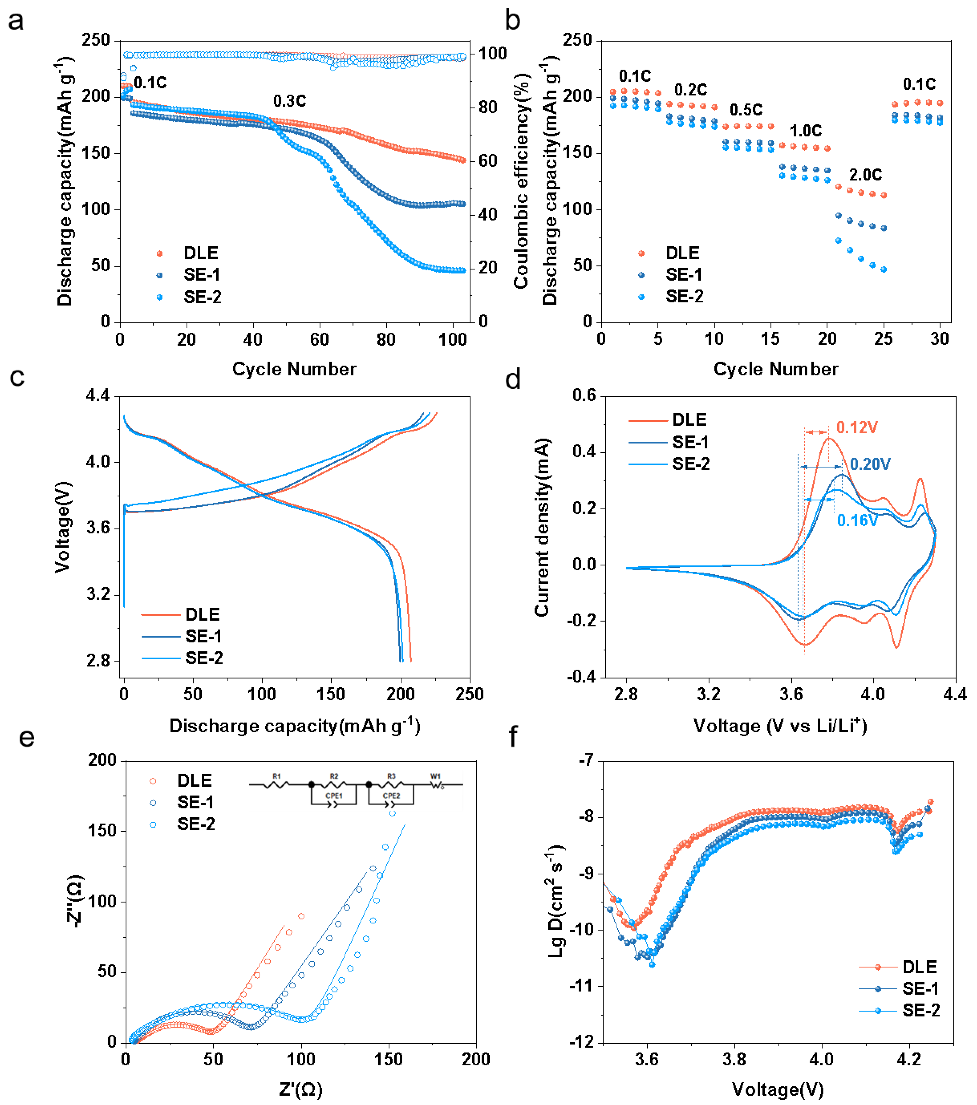
The electrochemical performance of the SE-1 and SE-2 electrodes was evaluated and compared against that of the DLE (DLE1:1). As depicted in Figure 3a, each electrode had a loading of 20 mg cm−2, and cycle tests at 0.3 C were conducted. The results reveal that the DLE demonstrated significantly better stability at higher cycle counts. In contrast, SE-1 started to exhibit noticeable capacity fade around 60 cycles, and SE-2 showed similar degradation around 40 cycles. Rate capability tests were also performed on the DLE, SE-1, and SE-2 electrodes at various rates: 0.1 C, 0.2 C, 0.5 C, 1.0 C, 2.0 C, and back to 0.1 C. Figure 3b illustrates that the DLE consistently delivered higher discharge-specific capacities across all tested rates compared to SE-1 and SE-2, with particularly notable differences at 1.0 C and 2.0 C. Additionally, Figure S3 shows the 0.1 C cycling and rate performance of electrodes after 300 kg hot-rolling at 80 °C, with trends consistent with those from samples compressed at 1.5 tons. This confirms the robustness of the dual-layer design across different compaction pressures.
The phenomena above are mainly caused by the charge accumulation of electrostatic force powder repulsion when less electron-conductive powders are deposited on a conductive surface. As the thickness of the deposited power layer increases, the total electron resistance increases. In addition, the more polymer binder contained, the higher the dielectric coefficient those powders possess. These two facts result in a more serious “orange peel effect,” meaning that deposited powders propel the incoming powders with the same type of charge, leading to roughness on the surface and therefore less regulated pore distribution, which is more vulnerable to polarization during cycling. The DLE preparing process could interrupt the accumulation of electrostatic force by applying a conductive roller to compress the base-layer surface, then deposit another thin layer to alleviate the orange peel effect, which could significantly increase the uniformity of pore distribution and acquire a better cycle performance. Furthermore, this superior high-ionic-diffusion process in DLE samples also can be attributed to the pore gradient formed by the upper- and base-layer design, which facilitates the insertion and extraction of lithium ions during cycling.
The charge and discharge curves of each electrode in the first cycle are shown in Figure 3c. The discharge-specific capacity of the DLE in the first cycle could reach 207.3 mAh g−1, while those of SE-1 and SE-2 were only 199.4 mAh g−1 and 201.4 mAh g−1, respectively. Cyclic voltammetry (CV) tests before cycling were carried out on the DLE, SE-1, and SE-2 at a scanning rate of 0.1 mV s−1, as shown in Figure 3d. By calculating the difference between the oxidation peak position and the reduction peak position, it was found that the value for the DLE was 0.12 V, while those for SE-1 and SE-2 were 0.20 V and 0.16 V, respectively. The oxidation peak position and the reduction peak position correspond to the charging voltage and discharging voltage platforms, respectively. DLE presents the highest coulombic efficiency with the smallest difference between the oxidation and reduction peak.
Furthermore, electrochemical impedance spectroscopy (EIS) tests were conducted on each electrode before cycling. The equivalent circuit, featuring two time-dependent Randles units and an open Warburg unit, is shown in Figure 3e as an inset. The main resistances of the DLE, SE-1, and SE-2 samples were 41.81 Ω, 65.08 Ω, and 96.52 Ω, respectively. The DLE showed the lowest electrochemical impedance, thereby reducing heat generation during high-rate charge/discharge operations.
Galvanostatic intermittent titration technique (GITT) tests were carried out on each electrode, and the results are presented in Figure 3f. During the electrochemical cycling process, the lithium-ion diffusion coefficient of the DLE electrode was measured at 1.11 × 10⁻⁸ cm2 s−1, which is higher than those of the SE-1 (1.06 × 10⁻⁸ cm2 s−1) and SE-2 (9.59 × 10⁻⁹ cm2 s−1) electrodes. The inflection point for the DLE in the first cycle was observed at 3.57 V, while those for SE-1 and SE-2 in their first cycles were located at 3.60 V and 3.61 V, respectively. These GITT data suggest that the more regulated pore structure of the DLE sample enhanced the lithium-ion insertion–extraction diffusion rate and lowered the activation potential required for lithium-ion transport. As shown in Figure S4a, after long-term testing, the lithium-ion diffusion coefficient of DLE was still higher than that of SE-1 and SE-2. Meanwhile, it can be seen from Figure S4b that the relaxation voltage of DLE was relatively small, which confirms that the bilayer structure could maintain an effective ion transport path even after long-term cycling. Figure S5 shows the electrode peel strength of DLE, SE-1 and SE-2 electrodes after rolling at 25 °C and 80 °C, and the results indicate that the design of the double-layer electrode improved the bonding strength of the electrode at room temperature and normal temperature. This is because an overly thick FM layer will cause the overall shedding of the electrode film, and an overly thick AM layer will result in low bonding strength of the electrode. When the thicknesses of the two layers is balanced, the optimal peeling strength of the electrode is achieved.
To evaluate the performance of the double-layer solvent-free electrode (DLE) against the traditional slurry-cast (SLC) electrode, a comparative study was performed. As shown in Figure 4a, at 0.3 C cycling, the DLE exhibited a capacity retention rate of 74% after 100 cycles, surpassing the 60% retention of the SLC. Figure S6 presents a comparison of EIS data for DLE and SLC samples, revealing a resistance of 52.11 Ω for the SLC samples. Rate capability tests were conducted on the DLE and SLC at rates of 0.1 C, 0.2 C, 0.5 C, 1.0 C, 2.0 C, and back to 0.1 C. As depicted in Figure 4b, the DLE demonstrated superior performance, particularly during high-rate cycling at 2.0 C. At this rate, the DLE achieved a discharge-specific capacity of 120.4 mAh g−1, which is significantly higher than the 58.2 mAh g−1 recorded for the SLC.
To investigate the internal structure of the electrodes, computed tomography (CT) scans were performed on both the slurry-cast (SLC) and the dual-layer solvent-free (DLE) electrodes, as shown in Figure 5a,b. In the CT imaging, orange/yellow regions depict high-density materials (active materials), green regions represent low-density materials (binders and conductive agents), and red regions show the pores within the electrodes. The CT images indicate a higher concentration of binders and conductive agents on the surface of the SLC electrode. This excess can result in poorer electrolyte wettability and may hinder lithium-ion transport pathways. Conversely, the DLE electrode demonstrated a uniform distribution of pores and low-density materials across its entire depth. This finding confirms that the mechanofusion coating remained intact during electrode fabrication, ensuring homogeneous component distribution. Such uniformity is essential for sustaining electrode performance and ensuring effective electrolyte wettability.
Furthermore, analysis of the orange regions in the CT images indicates that active materials were more uniformly distributed in the DLE than in the SLC cathodes. This uniformity stems from the dry-mixing process used in fabricating the DLE, which effectively prevents the uneven distribution and aggregation of active materials. In slurry-based methods, such issues can arise due to liquid solvents like NMP. Additionally, the dry process avoids electrode sheet shrinkage, which commonly occurs during the drying phase of slurry-cast coating processes due to solvent evaporation [39,40]. The pore, AM, and FM volume fractions of each electrode are shown in Table S2. The porosity of the DLE was lower than that of the SLC, which is due to the densification effect of the double-layer gradient hot-pressing process. The AM volume proportion of DLE was higher, directly supporting its higher energy density. The double-layer structure improved the electrochemical performance of the DLE compared with that of traditional slurry electrodes by reducing porosity and optimizing the pore size distribution and conductive network. The uniform and interconnected pore structure facilitated Li+ diffusion, and the optimized structure improved electrolyte wettability. In contrast, SE and SLC could not match the DLE’s optimized structure for electron and Li+ transmission.
As shown in Figure 5c, the tortuosity of the traditional SLC was 6.88, compared to 4.83 for the DLE, and the corresponding tortuosity calculation formula is shown as Equation S1. The lower tortuosity of the solvent-free samples can likely be attributed to the reduced local component variation during electrostatic spray deposition and roll-pressing. These processes ensure a uniform distribution of each component within the electrode. The regulated pore distribution from electrostatic deposition resulted in lower overall tortuosity for the DLE compared to the SLC electrode. Figure S7a,b show the captured images of the wettability tests for the DLE and SLC electrodes, respectively. Figure 5c presents the contact angles of the two electrodes, which were 33.7° and 44.2°, respectively. The lower contact angle of the DLE suggests better electrolyte absorbance, facilitating lithium-ion insertion and extraction from the active materials.
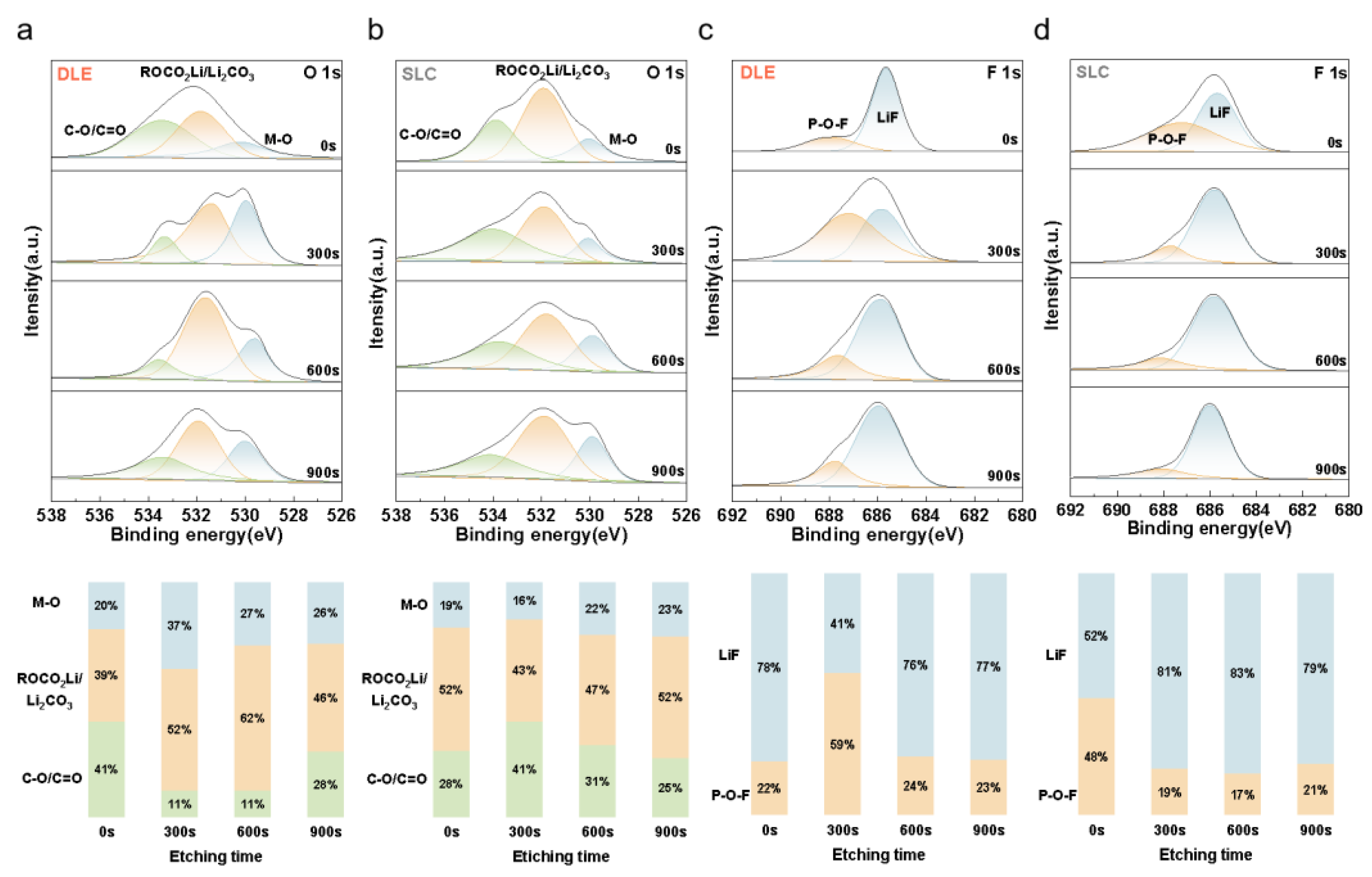
The XPS analysis of the cycled DLE and SLC samples is presented in Figure 6. Figure 6a,b show the O 1s XPS spectra and the corresponding component proportions for the DLE and SLC after cycling, with etching times of 0 s, 300 s, 600 s, and 900 s. The DLE exhibited higher proportions of metal–oxygen (M-O) bonds at all etching times (20%, 37%, 27%, and 26%) compared to the SLC (19%, 16%, 22%, and 23%). The ~532 eV peak is a characteristic peak typical of CEI components (such as ROCO2Li, Li2CO3), resulting from the reduction decomposition of the electrolyte on the positive electrode surface. Through the in-depth XPS analysis of the DLE and SLC electrodes after cycling, it was found that the peak intensity of the DLE electrode at ~532 eV increased compared with the initial state, indicating moderate growth of CEI. The peak intensity at ~534 eV slightly decreased, suggesting that solvent adsorption decreased due to the passivation effect of CEI. After the DLE cycle, the intensity of the peak (ROCO2Li/Li2CO3) at ~532 eV increased moderately, indicating the stable formation of CEI. The peak of SLC was significantly enhanced, revealing continuous electrolyte decomposition, which was consistent with its high impedance and capacity attenuation. The double-layer design reduced the electrolyte penetration through the rich binder bottom layer and inhibited the excessive growth of CEI, which is one of the key factors for improving the cycling stability.
Figure 6c,d display the F 1s XPS spectra and component proportions for the DLE and SLC after cycling at the same etching times. The LiF proportions of DLE were 78%, 41%, 76% and 77%, respectively, while those of SLC were 52%, 81%, 83%, and 79%. The initial high LiF content on the DLE surface was due to the fluorine element in the binder, which formed a fluorine-rich passivation layer on the electrode surface, stabilized the interface, and reduced the initial impedance. The LiF in the deep layer of SLC mainly came from the decomposition of the electrolyte (LiPF6) and gradually accumulated in the deep layer of CEI as the cycle proceeded, forming a thick and high-impedance interface layer. The root cause of the structural differences lies in the double-layer design of DLE, which restricted the formation of LiF to the surface through a rich binder base layer (FM layer), while the uniform structure of SLC led to deeper penetration of the electrolyte, triggering the global decomposition of CEI [41]. The time-of-flight secondary ion mass spectrometry (TOF-SIMS) analysis of the intermediate products during the electrode cycling process is shown in Figure S8. The gradient structure of DLE reduced the generation of by-products such as F and PO2 through the dual mechanisms of physical barrier and electrochemical stabilization. This is one of the core reasons why its cycling life and impedance characteristics are superior to those of traditional electrodes.
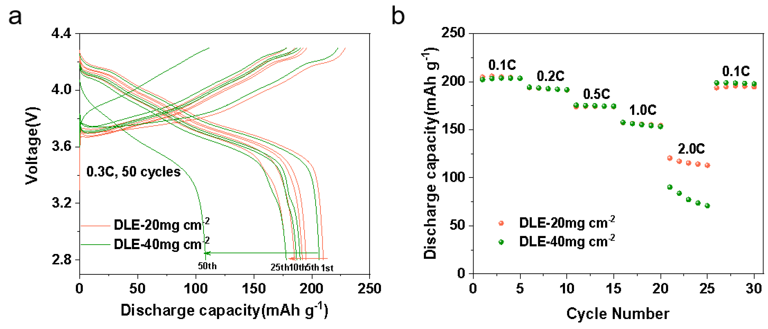
A performance comparison was conducted between DLE electrodes with high and low loading amounts. The thickness ratios of AM-rich to FM-rich were kept at 1:1 to achieve an overall electrode loading of 40 mg cm−2, as shown in Figure 7a, and cycling tests were performed at 0.3 C. Compared to the DLE with a loading amount of 20 mg cm−2, the DLE with 40 mg cm−2 exhibited noticeable capacity attenuation after approximately 25 cycles.
Similarly, the rate cycling results in Figure 7b show that at high rates (>2.0 C), the discharge-specific capacity of the high-loading DLE was lower than that of the low-loading DLE. This may be attributed to two factors: First, electrode expansion and swelling took place due to increased electrolyte absorption during cycling. Second, the “orange peel effect” (electrostatic repulsion effect) became more pronounced as each layer was thickened to achieve higher mass loading, leading to a less regulated pore structure in the electrostatically sprayed electrode. To address this issue of charge accumulation, future work will explore the use of ionizing air guns to remove excess charge from the base layer [42].

4. Conclusions

In this study, dual-layer NCM811 cathode electrodes were successfully fabricated via electrostatic spray deposition, showcasing their viability as a sustainable and high-performance alternative to traditional slurry-cast electrodes. The DLE’s distinctive structure, featuring an active material-rich upper layer and a binder–conductor-rich base layer, effectively boosted energy output, mechanical robustness, and electrochemical performance. The dual-layer solvent-free electrodes exhibited 14% higher discharge-specific capacities, better rate performance, and 14% higher cycling stability at 0.3C after 100 cycles compared to commercial slurry-cast electrodes, validating the efficacy of the solvent-free fabrication approach. Notwithstanding these advancements, significant challenges persist in scaling this technology for high-loading applications. Capacity attenuation and electrode detachment under heavy loading conditions remain critical issues that demand urgent attention. Future research endeavors should prioritize the optimization of electrode architecture, the mitigation of volumetric fluctuations, and the refinement of manufacturing protocols to suppress electrostatic charge buildup. These strategies are pivotal for achieving enhanced electrochemical performance and long-term stability. Overall, this study provides valuable insights into the development of next-generation lithium-ion battery technology, underscoring the crucial role of innovative electrode manufacturing methods in advancing sustainable green energy solutions.

Supplementary Materials

The following supporting information can be downloaded at: https://www.mdpi.com/article/10.3390/en18123112/s1, Supporting S1: Fitting of electrochemical impedance spectrometry data; Supporting S2: Calculation of tortuosity of lithium-ion transportation; Supporting S3: The choice of compression temperatures, pressures, and layer thicknesses; Table S1: Parameters related to each electrode; Table S2: The porosity of each electrode and the proportion of phase volume; Figure S1: Scanning electron microscope images of (a) single particle after mechanofusion mixing, (b) cross-section of the electrostatically sprayed deposited electrodes; Figure S2: Photo images: (a) the first layer of the electrode after cold pressing, (b) the second layer sprayed with the first layer as the target, (c) the final double-layer electrode after high temperature and high pressure; Figure S3: Half-cells assembled with DLE, SE-1, and SE-2 electrodes under a pressure of 300 kg: (a) cyclic curve at 0.1C, (b) cyclic curves at different magnifications; Figure S4: GITT curves of DE, SE-1, and SE-2: (a) relaxation curve during the first cycle, (b) lithium-ion diffusion curve over three cycles; Figure S5: Electrode peel strength of DLE, SE-1, and SE-2 electrodes after roller pressing at 25 °C and 80 °C; Figure S6: EIS tests and equivalent circuit simulation spectra of DLE and SLC electrodes; Figure S7: (a) Contact angle of the DLE for electrolyte wettability, (b) contact angle of the SLC for electrolyte wettability; Figure S8: The distribution of intermediate products F, PO2, NiF3, and MnF3 of each electrode.

Author Contributions

Conceptualization, N.L. and Z.W.; methodology, N.L. and Z.W.; investigation, H.G., C.Z. and Y.M.; data curation, H.G., C.Z. and Y.M.; writing—original draft, H.G.; writing—review and editing, N.L. and Z.W.; visualization, H.G., C.Z. and Y.M.; supervision, N.L. and Z.W.; project administration, N.L. and Z.W.; funding acquisition, Z.W. All authors have read and agreed to the published version of the manuscript.

Funding

This study was financially supported by the Science and Technology Program of Tianjin, China (24YDTPJC00140), and the Natural Science Foundation of Hebei Province, China (E2023202253).

Data Availability Statement

The data presented in this study are available upon request from the corresponding author.

Conflicts of Interest

The authors declare no conflicts of interest.

References

  1. Tarascon, J.M.; Armand, M. Issues and challenges facing rechargeable lithium batteries. Nature 2001, 414, 359–367. [Google Scholar] [CrossRef] [PubMed]
  2. Zhong, Y.J.; Cao, C.C.; Zhao, L.Q.; Tadé, M.O.; Shao, Z.P. Optimization of two-dimensional solid-state electrolyte–anode interface by integrating zinc into composite anode with dual-conductive phases. Green Carbon 2024, 2, 94–100. [Google Scholar] [CrossRef]
  3. Liu, C.C.; Jia, S.e.; Yang, T.Z.; Liu, J.B.; Zhou, X.R.; Wang, Z.F.; Dong, H.C.; Shi, Z.J.; Zhang, Y.G.; Chen, Z.W. Scalable and ultrathin dual entangled network polymer electrolytes for safe solid-state sodium batteries. Angew. Chem. 2025, e202505938. [Google Scholar] [CrossRef]
  4. Yang, H.J.; Naveed, A.; Li, Q.Y.; Guo, C.; Chen, J.H.; Lei, J.Y.; Yang, J.; Nuli, Y.; Wang, J.L. Lithium sulfur batteries with compatible electrolyte both for stable cathode and dendrite-free anode. Energy Storage Mater. 2018, 15, 299–307. [Google Scholar] [CrossRef]
  5. Liu, I.P.; Chen, Y.Y.; Cho, Y.S.; Wang, L.W.; Chien, C.Y.; Lee, Y.L. Double-layered printable electrolytes for highly efficient dye-sensitized solar cells. J. Power Sources 2021, 482, 228962. [Google Scholar] [CrossRef]
  6. Meng, Z.Y.; Xu, Z.Q.; Li, H.; Xiong, H.Q.; Liu, X.J.; Qin, C.L.; Wang, Z.F. Silicon/biomass carbon composite as a low-cost anode for lithium-ion batteries. Energies 2025, 18, 972. [Google Scholar] [CrossRef]
  7. Qi, W.; Lai, Y.Q.; Liu, F.Y.; Jiang, L.X.; Ming, J.; Wang, X.L. Sb2S3 nanorods/porous-carbon composite from natural stibnite ore as high-performance anode for lithium-ion batteries. Trans. Nonferrous Met. Soc. China 2021, 31, 2051–2061. [Google Scholar] [CrossRef]
  8. Houache, M.S.; Yim, C.-H.; Karkar, Z.; Abu-Lebdeh, Y. On the current and future outlook of battery chemistries for electric vehicles—Mini review. Batteries 2022, 8, 70. [Google Scholar] [CrossRef]
  9. Liu, L.J.; Wang, T.; Sun, L.; Song, T.L.; Yan, H.; Li, C.L.; Mu, D.B.; Zheng, J.C.; Dai, Y. Stable Cycling of All-Solid-State Lithium Metal Batteries Enabled by Salt Engineering of PEO-Based Polymer Electrolytes. Energy Environ. Mater. 2024, 7, e12580. [Google Scholar] [CrossRef]
  10. Liu, Z.D.; Wang, C.Y.; Zhang, J.C.; Luo, J.W.; Zeng, C.H.; Liu, W.D.; Liu, R.; Chen, Y.N. Co-free/Co-poor high-Ni cathode for high energy, stable and low-cost lithium-ion batteries. Rare Met. 2023, 42, 2214–2225. [Google Scholar] [CrossRef]
  11. Mi, C.; Wang, Z.G.; Yang, S.B.; Liu, X.J.; Wang, Y.C.; Wang, Z.F. Porous Al11Ce3 intermetallics as effective sulphur host networks for stable lithium–sulphur batteries. J. Mater. Chem. C 2025, 13, 9014–9026. [Google Scholar] [CrossRef]
  12. Yang, X.; Tat, T.; Libanori, A.; Cheng, J.; Xuan, X.X.; Liu, N.; Yang, X.; Zhou, J.H.; Nashalian, A.; Chen, J. Single-atom catalysts with bimetallic centers for high-performance electrochemical CO2 reduction. Mater. Today 2021, 45, 54–61. [Google Scholar] [CrossRef]
  13. Liu, Q.; Wang, L.; He, X.M. Toward practical solid-state polymer lithium batteries by in situ polymerization process: A review. Adv. Energy Mater. 2023, 13, 2300798. [Google Scholar] [CrossRef]
  14. Wang, Z.F.; Wang, H.Y.; Liu, X.L.; Chen, Y.X.; Zhao, Y.; Zhang, Y.G.; Han, Q.Q.; Qin, C.L.; Bakenov, Z.; Wang, Y.C. Single Zn atoms anchored on hollow carbon nanofiber network for dendrite-free lithium metal anode of flexible Li–S full cell. Rare Met. 2023, 42, 3705–3717. [Google Scholar] [CrossRef]
  15. Fei, F.; Wen, Z.G.; De Clercq, D. Spatio-temporal estimation of landfill gas energy potential: A case study in China. Renew. Sustain. Energy Rev. 2019, 103, 217–226. [Google Scholar] [CrossRef]
  16. Awasthi, S.; Moharana, S.; Kumar, V.; Wang, N.; Chmanehpour, E.; Sharma, A.D.; Tiwari, S.K.; Kumar, V.; Mishra, Y.K. Progress in doping and crystal deformation for polyanions cathode based lithium-ion batteries. Nano Mater. Sci. 2024, 6, 504–535. [Google Scholar] [CrossRef]
  17. Sun, X.; Qin, C.L.; Zhao, B.Y.; Jia, S.F.; Wang, Z.F.; Yang, T.Z.; Liu, X.C.; Pan, L.N.; Zheng, L.L.; Luo, D. A cation and anion dual-doping strategy in novel Li-rich Mn-based cathode materials for high-performance Li metal batteries. Energy Storage Mater. 2024, 70, 103559. [Google Scholar] [CrossRef]
  18. Wang, Z.F.; Yan, Y.J.; Zhang, Y.G.; Chen, Y.X.; Peng, X.Y.; Wang, X.; Zhao, W.M.; Qin, C.L.; Liu, Q.; Liu, X.J. Single-atomic Co-B2N2 sites anchored on carbon nanotube arrays promote lithium polysulfide conversion in lithium–sulfur batteries. Carbon Energy 2023, 5, e306. [Google Scholar] [CrossRef]
  19. Kim, N.Y.; Kim, J.H.; Koo, H.; Oh, J.; Pang, J.H.; Kang, K.D.; Chae, S.S.; Lim, J.; Nam, K.W.; Lee, S.Y. Material challenges facing scalable dry-processable battery electrodes. ACS Energy Lett. 2024, 9, 5688–5703. [Google Scholar] [CrossRef]
  20. Tao, R.M.; Steinhoff, B.; Sawicki, C.H.; Sharma, J.; Sardo, K.; Bishtawi, A.; Gibbs, T.; Li, J.L. Unraveling the impact of the degree of dry mixing on dry-processed lithium-ion battery electrodes. J. Power Sources 2023, 580, 233379. [Google Scholar] [CrossRef]
  21. Ryu, M.; Hong, Y.K.; Lee, S.Y.; Park, J.H. Ultrahigh loading dry-process for solvent-free lithium-ion battery electrode fabrication. Nat. Commun. 2023, 14, 1316. [Google Scholar] [CrossRef] [PubMed]
  22. He, R.J.; Zhong, W.; Cai, C.Y.; Li, S.P.; Cheng, S.J.; Xie, J. Flour-infused dry processed electrode enhancing lithium-ion battery performance. Adv. Energy Mater. 2024, 14, 2402109. [Google Scholar] [CrossRef]
  23. Horst, M.; Beverborg, F.; Bahlmann, L.; Schreiber, S.; Gerk, J.; Michalowski, P.; Kwade, A. Effect of active material morphology on PTFE-fibrillation, powder characteristics and electrode properties in dry electrode coating processes. Powder Technol. 2025, 451, 120451. [Google Scholar] [CrossRef]
  24. Ma, Y.J.; Guo, H.J.; Yang, T.; Wang, Z.F. Structural design of dry-processed lithium-rich Mn-based materials with high loading for enhanced energy density. Batteries 2025, 11, 146. [Google Scholar] [CrossRef]
  25. Kirsch, D.J.; Lacey, S.D.; Kuang, Y.D.; Pastel, G.; Xie, H.; Connell, J.W.; Lin, Y.; Hu, L.B. Scalable dry processing of binder-free lithium-ion battery electrodes enabled by holey graphene. ACS Appl. Energy Mater. 2019, 2, 2990–2997. [Google Scholar] [CrossRef]
  26. Liu, J.; Ludwig, B.; Liu, Y.T.; Zheng, Z.F.; Wang, F.; Tang, M.; Wang, J.J.; Wang, J.; Pan, H.; Wang, Y. Scalable dry printing manufacturing to enable long-life and high energy lithium-ion batteries. Adv. Mater. Technol. 2017, 2, 1700106. [Google Scholar] [CrossRef]
  27. Ludwig, B.; Zheng, Z.F.; Shou, W.; Wang, Y.; Pan, H. Solvent-free manufacturing of electrodes for lithium-ion batteries. Sci. Rep. 2016, 6, 23150. [Google Scholar] [CrossRef]
  28. Oh, H.; Kim, G.S.; Bang, J.; Kim, S.; Jeong, K.M. Dry-processed thick electrode design with a porous conductive agent enabling 20 mAh cm−2 for high-energy-density lithium-ion batteries. Energy Environ. Sci. 2025, 18, 645–658. [Google Scholar] [CrossRef]
  29. Park, D.; Kim, S.; Ha, S.; Hwa, Y.; Kim, J.; Park, J.; Son, Y. Pitch-based quasi-dry thick electrode fabrication process of NCM cathode for lithium-ion batteries. J. Power Sources 2024, 614, 235037. [Google Scholar] [CrossRef]
  30. Yonaga, A.; Kawauchi, S.; Mori, Y.; Xuanchen, L.; Ishikawa, S.; Nunoshita, K.; Inoue, G.; Matsunaga, T. Effects of dry powder mixing on electrochemical performance of lithium-ion battery electrode using solvent-free dry forming process. J. Power Sources 2023, 581, 233466. [Google Scholar] [CrossRef]
  31. Zhang, Y.D.; Wang, D.H.; Liang, C.F.; Han, Y.; Li, Z.; Huang, Y.H. Design of double layer cathode electrode for improving the safety and stability of lithium-ion batteries. Chem. Eng. J. 2024, 495, 153344. [Google Scholar] [CrossRef]
  32. Chen, W.B.; Wang, K.; Li, Y.L.; Chen, J.; Wang, H.B.; Li, L.W.; Li, H.; Ren, X.Z.; Ouyang, X.P.; Liu, J.H. Minimize the electrode concentration polarization for high-power lithium batteries. Adv. Funct. Mater. 2024, 34, 2410926. [Google Scholar] [CrossRef]
  33. Kang, J.; Lim, J.; Lee, H.; Park, S.; Bak, C.; Shin, Y.; An, H.; Lee, M.; Lee, M.; Lee, S. Sequential effect of dual-layered hybrid graphite anodes on electrode utilization during fast-charging Li-ion batteries. Adv. Sci. 2024, 11, 2403071. [Google Scholar] [CrossRef]
  34. Shi, H.F.; Niu, S.Z.; Lv, W.; Zhou, G.M.; Zhang, C.; Sun, Z.H.; Li, F.; Kang, F.Y.; Yang, Q.H. Easy fabrication of flexible and multilayer nanocarbon-based cathodes with a high unreal sulfur loading by electrostatic spraying for lithium-sulfur batteries. Carbon 2018, 138, 18–25. [Google Scholar] [CrossRef]
  35. Song, K.F.; Zhang, C.; Hu, N.F.; Wu, X.K.; Zhang, L. High performance thick cathodes enabled by gradient porosity. Electrochim. Acta 2021, 377, 138105. [Google Scholar] [CrossRef]
  36. Liu, T.; Li, X.C.; Sun, S.M.; Sun, X.L.; Cao, F.T.; Ohsaka, T.; Wu, J.F. Analysis of the relationship between vertical imparity distribution of conductive additive and electrochemical behaviors in lithium ion batteries. Electrochim. Acta 2018, 269, 422–428. [Google Scholar] [CrossRef]
  37. Chen, L.C.; Liu, D.; Liu, T.J.; Tiu, C.; Yang, C.R.; Chu, W.B.; Wan, C.C. Improvement of lithium-ion battery performance using a two-layered cathode by simultaneous slot-die coating. J. Energy Storage 2016, 5, 156–162. [Google Scholar] [CrossRef]
  38. Wulandari, T.; Fawcett, D.; Majumder, S.B.; Poinern, G.E. Lithium-based batteries, history, current status, challenges, and future perspectives. Battery Energy 2023, 2, 20230030. [Google Scholar] [CrossRef]
  39. Yang, X.P.; Cheng, F.; Ka, O.; Wen, L.; Gu, X.Y.; Hou, W.T.; Lu, W.; Dai, L.M. High-voltage lithium-ion capacitors enabled by a multifunctional phosphite electrolyte additive. Energy Storage Mater. 2022, 46, 431–442. [Google Scholar] [CrossRef]
  40. Jaiser, S.; Sanchez Salach, N.; Baunach, M.; Scharfer, P.; Schabel, W. Impact of drying conditions and wet film properties on adhesion and film solidification of lithium-ion battery anodes. Dry. Technol. 2017, 35, 1807–1817. [Google Scholar] [CrossRef]
  41. Zhong, W.H.; Tao, J.M.; Chen, Y.; White, R.G.; Zhang, L.; Li, J.X.; Huang, Z.G.; Lin, Y.B. Unraveling the evolution of Cathode–Solid electrolyte interface using operando X-ray Photoelectron spectroscopy. Adv. Powder Mater. 2024, 3, 100184. [Google Scholar] [CrossRef]
  42. Liu, W.B.; Li, D.Y.; Liu, Y.Q.; Luo, D.; Xu, R. A critical review of single-crystal LiNixMnyCo1-x-yO2 cathode materials. Renewables 2024, 2, 25–51. [Google Scholar] [CrossRef]
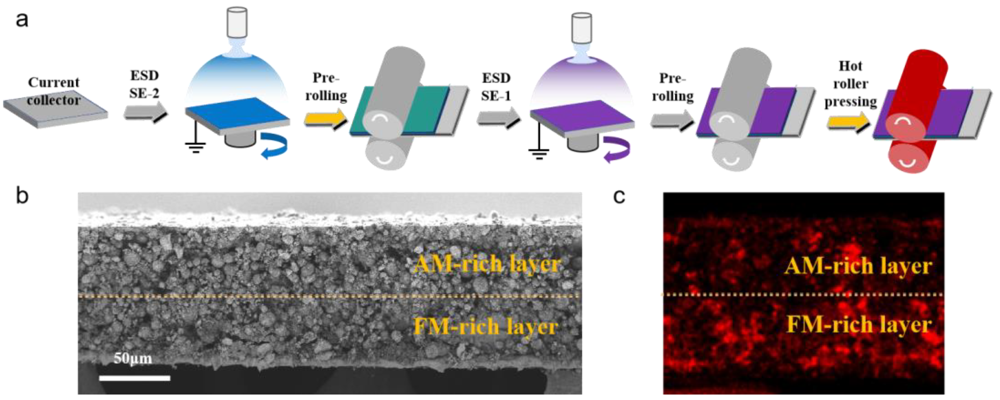
Figure 1. (a) Schematic of the electrostatic spraying process. (b) SEM and (c) EDX images of the dual-layered cross-section with an active material-rich layer and a functional material-rich layer, where red represents the distribution of fluorine.
Energies 18 03112 g001
Figure 2. Semi-cells were assembled using DLE electrodes with thickness ratios of 1:1, 1:2, and 2:1 (AM-rich:FM-rich). (a) Cycling curves at 0.5 C. (b) Rate cycling curves at different C-rates.
Energies 18 03112 g002
Figure 3. Performance evaluation of half-cells assembled with DLE, SE-1, and SE-2 electrodes. (a) Discharge capacity curves at a rate of 0.3 C. (b) Discharge capacity curves at different rates. (c) First charge–discharge curve at 0.1 C. (d) Cyclic voltammetry (CV) curve at a scan rate of 0.1 mV s−1. (e) Electrochemical impedance spectroscopy (EIS) curve; the inset image shows the equivalent circuit used for simulating EIS data. (f) Lithium-ion diffusion coefficient curve during 0.1 C cycling.
Energies 18 03112 g003
Figure 4. Performance evaluation of half-cells assembled with DLE and SLC electrodes. (a) Cycling curves at 0.3 C. (b) Cycling curves at different rates.
Energies 18 03112 g004
Figure 5. Performance evaluation of half-cells assembled with DLE and SLC electrodes. (a) Micro-CT scans of the DLE electrode. (b) Micro-CT scans of the SLC electrode. (c) Comparison of electrode tortuosity and contact angle, reflecting electrolyte wettability.
Energies 18 03112 g005
Figure 6. O 1s and F 1s XPS spectra of cycled electrodes: (a) O 1s for DLE, (b) O 1s for SLC, (c) F 1s for DLE, and (d) F 1s for SLC.
Energies 18 03112 g006
Figure 7. (a) Charge and discharge curves of DLE at high and low loadings. (b) Discharge-specific capacity curves at different rates for DLE under high and low loadings.
Energies 18 03112 g007
Disclaimer/Publisher’s Note: The statements, opinions and data contained in all publications are solely those of the individual author(s) and contributor(s) and not of MDPI and/or the editor(s). MDPI and/or the editor(s) disclaim responsibility for any injury to people or property resulting from any ideas, methods, instructions or products referred to in the content.