1. Introduction
Precise temperature control in high-temperature thermal processes remains a critical challenge across various sectors in industry and research. PID control systems find extensive use in applications such as pasteurization systems employing report pouches for food safety [
1]. In metal heat treatment, PID controllers facilitate accurate heating profiles, critical for achieving desired material properties and structural integrity. Similarly, in glass production, precise temperature management ensures product consistency, optical clarity, and structural uniformity, while chemical manufacturing processes depend on PID control for reaction efficiency and product purity [
2]. Additionally, electrical furnaces rely on advanced PID strategies like the RPIDD2 controller to enhance stability and achieve rapid thermal response in industrial processes [
3]. Nuclear power systems employ PID controllers to effectively manage reactor temperature, ensuring safe operation and maintaining stability during transient conditions [
4]. In electric vehicle battery thermal management, PID control is essential for optimizing charging processes and battery lifespan by precisely regulating battery temperatures [
5]. Hybrid maritime microgrids utilize PID controllers to balance thermal and electrical loads, enhancing operational reliability and efficiency [
6]. PID control strategies are also critical in managing thermal dynamics in high-temperature superconducting (HTS) magnets, used in advanced research facilities to maintain stable operation conditions [
7]. Precise temperature regulation in small-pressurized water reactors (SPWRs) via PID control contributes significantly to maintaining operational safety and efficiency under dynamic load conditions [
8]. These diverse applications underline the versatility and critical importance of PID control in modern engineering systems dealing with complex thermal processes. In all these applications, maintaining precise temperature control is essential to ensure product quality, energy efficiency and safety, prevent material degradation, and maintain process efficiency. The PID controller is the workhorse of industrial temperature control, used in most control loops due to its simplicity and reliability [
6,
9]. It is estimated that over 90% of industrial controllers employ PID or a PID-based architecture [
10,
11].
PID controllers adjust process behavior via three gains: proportional (Kp), integral (Ki), and derivative (Kd) to achieve fast and stable regulation with minimal steady-state error. In practice, PID loops are indeed very effective at reacting quickly to disturbance and setpoint changes, which is why they dominate industrial furnace control. However, high-temperature processes present unique challenges that can push conventional PID control to its limits. Industrial equipment that works at high temperatures often exhibits strongly nonlinear dynamics, time-varying parameters, sensor limitations, and significant thermal inertia that make fixed PID settings suboptimal [
12]. Nonlinearities arise prominently in radiative heat transfer, where thermal flux adheres to the Stefan–Boltzmann temperature relationship [
13], creating complex interdependencies between temperature and energy exchange. Time-varying parameters, such as convection coefficients, exhibit significant variability across operational temperatures ranges, as quantified by Dittus–Boeter correlations [
14]. Sensor limitations further exacerbate control challenges, for instance, K-type thermocouples demonstrate accuracy degradation (
) at subzero temperatures due to nonlinearities in their Seabeck coefficients [
15]. The tendency of a material or system to resist changes in temperature due to its stored thermal energy can severely affect the dynamic response of a control system, resulting in significant deviation from the desired temperature setpoint, particularly during transient phases. Collectively, these factors lead to sluggish response, significant overshoot, or oscillations during transients [
16], and, in extreme cases, safety-critical failures in applications such as nuclear reactor pressure vessel heating or risk damaging equipment [
4,
17]. These challenges underscore the need for adaptive and intelligent online control strategies capable of handling nonlinearities and time-varying behavior in high-temperature thermal systems.
Traditional PID tuning rules (Ziegler–Nichols, Cohen–Coon) often produce inadequate robustness in delay-dominated systems. Modern optimization-based methods embed robustness criteria directly into the tuning process, typically via constraints on maximum sensitivity or gain/phase margins. The research in [
18] introduced an optimal disturbance rejection PI tuning method by constraining the relative delay margin, demonstrating superior load disturbance attenuation and stability compared to classic rules. Fuzzy logic controllers employ a model-free approach that facilitates seamless control by assigning degrees of truth between 0 and 1. In fuzzy-PID schemes, if-then rules grounded in linguistic terms such as “high error” are used to adjust PID gains in real time, thereby enabling effective management of nonlinear dynamics. The main advantage of fuzzy control is its capacity to function without an exact process model, thereby accommodating nonlinearities through the utilization of expertly defined rules. Nevertheless, its efficacy is contingent upon a meticulously designed rule base and membership functions, which might necessitate recalibration in the event of alterations in operating conditions. The research in [
19] applied a fuzzy self-turning PID controller to an electric resistance furnace, achieving improved stability and eliminating steady-state error. More recently, ref. [
20] developed a fuzzy PID control system for an industrial heating furnace, demonstrating better temperature tracking and reduced overshoot compared to the conventional PID. Furthermore, Ref. [
21] combined genetic algorithm optimization with a fuzzy PID controller in a vacuum annealing furnace, significantly improving temperature response speed and stability compared to both conventional PID and a standard fuzzy-PID approach. Evolutionary optimization algorithms provide a data-driven way to automatically search for optimal PID gains by mimicking natural selection processes. Methods such as genetic algorithms (GAs) iteratively evaluate candidate solutions to improve performance. The research in [
16] used GA to optimize furnace PID gains, achieving faster settling and reduced overshoot compared to classical tuning. The research in [
22] proposed a refined metaheuristic method that enhanced the furnace’s dynamic response. While evolutionary tuning can outperform manual PID adjustments, these methods typically incur high computational cost and are often applied offline, limiting their real-time adaptability. A comparative study in [
12] evaluated several adaptive controllers: adaptive PID, dual-adaptive PID and adaptive gain fractional-order PID (FO-PID) on a nonlinear thermal system. Among the tested controllers, the FO-PID achieved the shortest settling time with zero overshoot under disturbances. This outcome aligns with recent reviews indicating that fractional-order PID controllers provide superior control flexibility and robust disturbance rejection in heating applications [
23]. These results highlight the performance gains offered by advanced PID designs in complex thermal processes. In recent years, interest in adaptive PID control has continued to grow, with modern approaches exploring rule-based self-tuning, Lyapunov-based adaptation, and reinforcement learning for automatic PID gain adjustment [
24].
Artificial neural networks provide a learning-based approach for adaptive PID control by approximating nonlinear relationships between system states and optimal controller gains. Once trained to represent process data, ANN can continuously adjust PID parameters in real time, enabling rapid adaptation to varying thermal conditions. Early implementations [
25] demonstrated an early ANN-based PID controller for a resistance furnace, confirming improved temperature regulation compared to manual tuning. In terms of more architectures, Ref. [
26] proposed a double-layer backpropagation ANN that outperformed a conventional single-layer design in adaptive PID control, and ref. [
27] integrated an ANN-based Smith predictor with a PID loop to manage a multi-zone thermal system, significantly improving temperature tracking and stability. Similarly, ref. [
28] demonstrated that an ANN-based controller on a rubber extrusion line could correct temperature deviations and maintain markedly more stable control than a fixed-gain PID. ANN-driven controllers can learn complex process dynamics and maintain performance even as system parameters drift; however, they require sufficient training data, proper network design to ensure stability, and adequate computational resources for real-time inference.
Model-based methods like the Smith predictor and model predictive control (MPC) use explicit process models to anticipate system behavior and optimize control actions over a future horizon. The Smith predictor compensates for known delays using a parallel model, while MPC solves an optimization problem at each step to determine the best control input. These methods can achieve excellent performance when the process model is accurate, but model mismatches can degrade controller effectiveness. For example, Ref. [
29] implemented a Smith-predictor-based scheme on a refinery furnace and found that the controller had to be re-tuned at different operating temperatures to account for changes in the plant gain, underscoring the need for model updates. Similarly, Ref. [
30] used a neural network to replace the process model within an MPC framework, improving real-time performance in a complex annealing system. In their design, the neural network forecasts the strip temperature in the heating section of the furnace, which is then used by a three-layer optimization controller composed of a set-point optimizer, a timing optimizer, and a steady-state compensator. This approach enhanced tracking accuracy and reduced control variability while operating under realistic industrial constraints. The research in [
31] applied a nonlinear MPC with a Takagi–Sugeno fuzzy inference system (functionally analogous to a shallow neural network) to a high-temperature rector, achieving faster responses and greater robustness than a fixed PID. Model-based schemes offer predictive control and systematic constraint handling, but they are computationally intensive and sensitive to model errors. Hybrid strategies have been explored to address drifting conditions, such as periodically re-optimizing PID parameters via particle swarm optimization [
32]. Another innovative approach involves cascade control combining a conventional PID loop with an outer model-free controller; ref. [
33] reported that this scheme outperformed standard cascades in accuracy and adaptability on a challenging furnace system. In general, a trend in the field is toward hybrid controllers that combine the reliability of classic PID loops with auxiliary intelligence such as AI or advanced algorithms to handle regimes where the PID alone falls short. This trend reflects the broader industry 4.0 movement to introduce learning and adaptation into traditional control systems for improved flexibility.
In this context, the present work contributes a fully validated design and implementation of an adaptive PID controller enhanced by a pretrained artificial neural network for temperature regulation in a high-temperature resistive furnace. Unlike prior studies limited to simulation or software in the loop evaluations, our solution was developed and field-tested on a retrofitted 18 kW industrial furnace for more than 120 h of cumulative operation. Due to the limitations of LabVIEW in executing neural inference natively, we adopted a non-intrusive Python (version 3.12, 2014)-LabVIEW (version. 12.01, 2012) file exchange bridge that preserves the legacy HMI while enabling online gain updates. A benchmark on commodity CPU hardware confirmed an inference latency of 0.0536 ms per prediction (≈18,800 predictions s−1), satisfying soft real-time constraints by three orders of magnitude. The entire furnace system, including the heating resistors, fan motor, and cooling damper, was redesigned and automated to facilitate precise thermal control. Finally, experiments showed that our ANN-tuned PID outperforms both fixed-gain PID and a rule-based fuzzy controller. Importantly, this work lays a solid foundation for validated construction and deployment of intelligent thermal control systems that can be adapted to broader applications, such as nuclear cooling processes or aerospace test environments, where thermal dynamics must be precisely and safely managed.
Finally, the article is structured as follows.
Section 1 introduces the background and motivation for adaptive PID control in high-temperature environments.
Section 2 presents the methodology, including the equipment retrofitting, hardware implementation, control architecture, ANN training strategy, and real-time implementation.
Section 3 discusses experimental results about neural network training, PID dynamic and adaptative control.
Section 4 outlines the conclusions and highlights future directions to enhance early-phase control and dynamic accuracy. This structured approach reflects a validated path from theory to application, emphasizing the practical viability of ANN-assisted PID control in demanding high-temperature thermal systems.
2. Methodology
2.1. Description of Thermal Equipment
The equipment used corresponds to a Blue-M type electric furnace, which was completely repowered both in its mechanical part and in its control system. Originally, this furnace had a manual heating system, so it was completely redesigned to automate its operation and allow more precise control of the temperature by means of PID control techniques and neural networks.
During the heating stage, the heat flow is generated by industrial-type electrical resistors distributed on the sides of the thermal chamber. This heat is mobilized by a centrifugal fan coupled to a three-phase squirrel cage motor, whose speed is kept constant during this phase to allow uniform heat distribution without generating significant temperature losses. In the cooling stage, an automated system based on a servomotor that opens a heat exhaust damper was implemented. This damper allows the hot air to escape to the environment, facilitating a gradual and controlled reduction in the temperature in the furnace chamber. The opening of this damper is synchronized with the speed variation of the fan motor, controlled by a SIEMENS SINAMICS G110 variable frequency drive, which receives 0–10 V analog signals from the NI USB-6009 data acquisition card.
The overall control of the system, including the fan drive, the resistors and the exhaust damper, is managed from a graphical interface developed in LabVIEW, which allows the computer to communicate with the actuators through a Data Acquisition (DAQ) card, thus facilitating real-time monitoring and automatic data acquisition during the entire thermal process.
Figure 1 shows the representative schematics of the furnace during its two operational phases: (a) heating and (b) cooling. In both operational phases, the system guarantees effective thermal control, regulating both heat input during heating and heat removal during cooling.
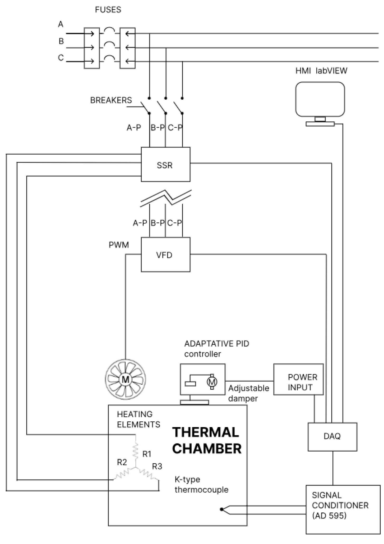
2.2. System Architecture and Hardware Implementation
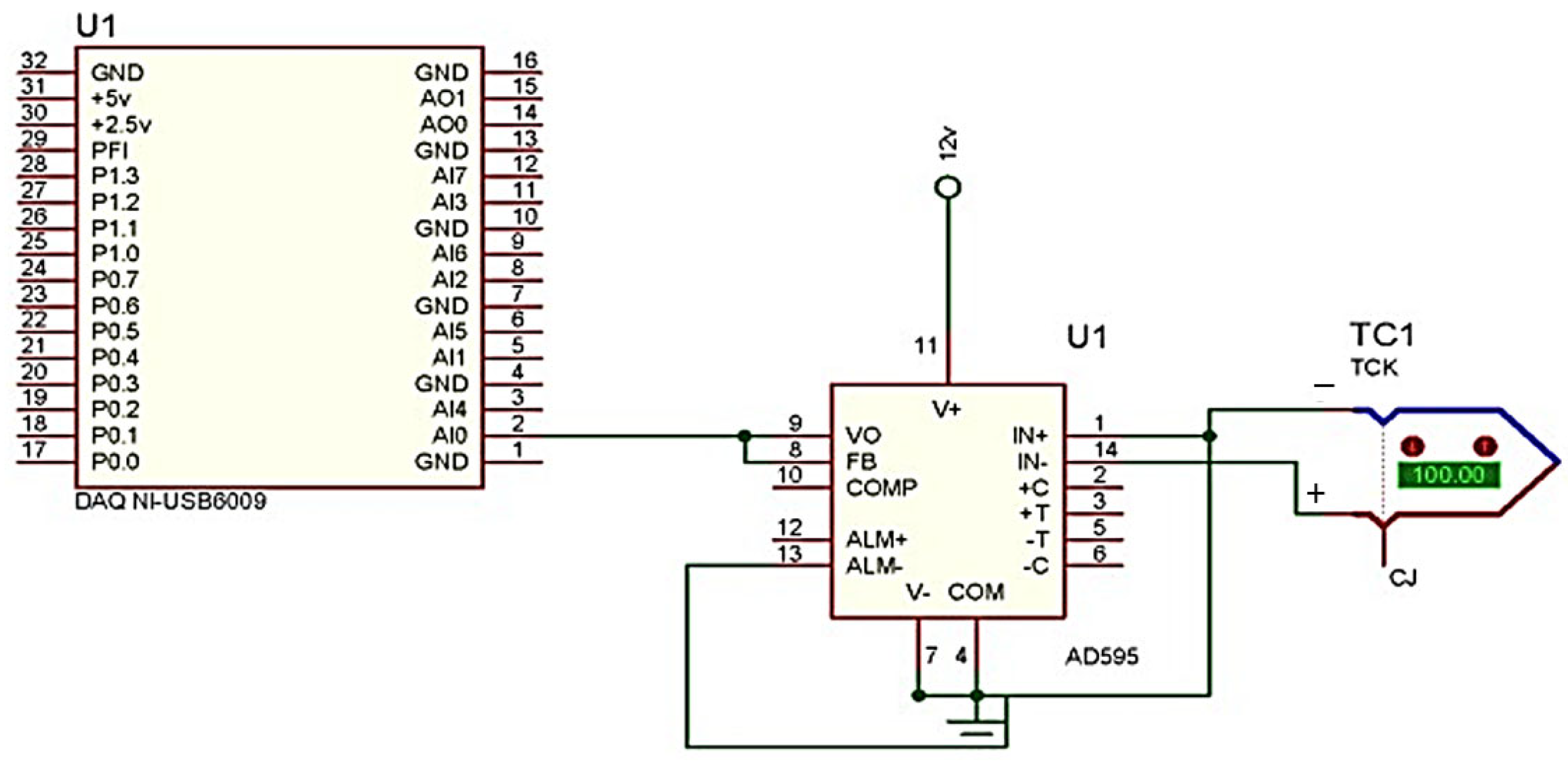
The control system is composed of multiple hardware and software components integrated to regulate the internal temperature of a repowered Blue-M convection furnace. The system includes the furnace chamber (the plant), a PID controller with coefficients dynamically tuned using a neural network, a data acquisition card (NI USB-6009), K-type thermocouples for temperature measurement, electric heating elements serving as actuators, a variable frequency drive (VFD) to control the speed of the ventilation motor, and a servomechanism that actuates the thermal exhaust flap. The control loop begins with the temperature acquisition using a K-type thermocouple, whose signal is conditioned via an AD595 signal conditioning circuit; see
Figure 2.
This conditioned analog signal is then transmitted to a virtual instrumentation interface developed in LabVIEW, which enables real-time visualization and logging of process variables. Additionally, this interface facilitates the execution of a custom-defined temperature-versus-time profile and the dynamic adjustment of the PID control parameters.
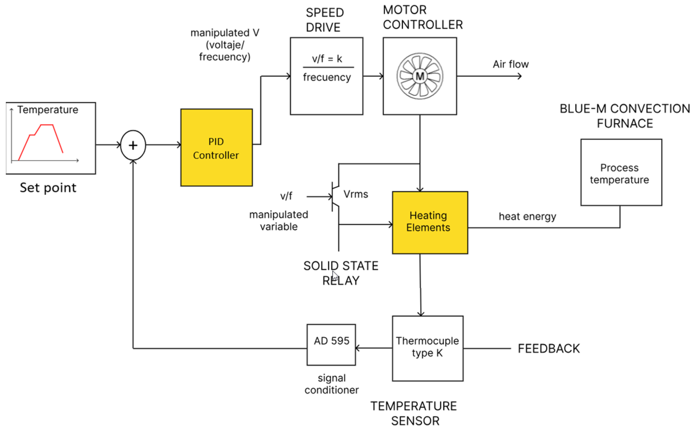
Figure 3 shows that the PID controller generates control signals that modulate two main actuators in the system:
A voltage signal that regulates the VFD, which in turn adjusts the speed of the airflow motor using a predefined voltage-to-frequency (V/f) ratio;
A separate voltage signal delivered to a solid-state relay, which controls the power supplied to the heating elements.
These control actions allow for precise adjustment of both the heating power and the air circulation within the furnace chamber, ensuring stable thermal conditions and rapid response to deviations from the set temperature.
The physical implementation of the thermal control system consists of several fundamental components that work together to achieve precise temperature regulation within the Blue-M furnace chamber. The main elements of the system are detailed below:
Heating system: The heating setup is composed of three 1000 W industrial electric resistors, connected in a delta configuration to ensure a balanced three-phase load. These resistors are controlled via a solid-state relay (SSR) operating under an integral-cycle switching scheme, which modulates the power delivered to the resistors based on the control signal generated by the PID controller [
34,
35,
36].
Cooling system: The cooling phase is managed by an automated exhaust flap, which facilitates the release of hot air from the chamber. This flap is actuated by a HITEC HS-311 servomotor, which receives pulse-width modulated (PWM) signals triggered by the LabVIEW interface. The mechanical design includes a chain, sprocket, and transmission shaft to ensure proper operation without overheating the servomotor [
36,
37,
38].
Internal thermal distribution: To ensure thermal homogeneity within the furnace chamber, a centrifugal fan driven by a three-phase squirrel cage induction motor was installed. The fan’s speed is regulated by a SIEMENS SINAMICS G110 VFD, which receives an analog 0–10 V signal from the DAQ card. This control enables real-time adjustment of airflow, enhancing the system’s thermal stability during the heating and cooling cycles.
Data acquisition: An NI USB-6009 data acquisition card was used to read analog and digital signals and to issue control outputs to the system’s actuators. Signal conditioning circuits were implemented to protect the DAQ inputs by limiting voltage and current levels. This device serves as the communication bridge between the system hardware and the LabVIEW-based software interface, allowing real-time data acquisition and control [
36,
39,
40].
Human–machine interface: A LabVIEW HMI was developed to allow the operator to monitor the system in real time, configure temperature ramps, and visualize the evolution of both PID and fuzzy control parameters. It also provides logging capabilities and supports simulation scenarios prior to physical operation.
The overall architecture of the system is shown in
Figure 4, where the interconnection between key physical components is illustrated, including the adaptive PID controller, DAQ system, actuators (SSR, VFD, servomotor), heating elements, fan motor, and the LabVIEW interface [
36,
41].
2.3. Thermal Profile and Setpoint Definition
To evaluate the behavior of the repowered furnace under controlled conditions, a thermal profile composed of multiple heating, stabilization and cooling sections was designed. This profile, represented in
Figure 5, was implemented using the LabVIEW interface and used as a reference for the PID-based control system. Each point in the profile establishes a target temperature that the system must reach and maintain during a specific time interval. These values are referred to as setpoints, i.e., setpoint values that represent the desired state of the system at each stage of the thermal process.
The profile starts with a heating ramp of 8 °C/min to reach 200 °C in 10 min, followed by a more gradual rise of 5 °C/min to reach 300 °C, where it is maintained for 15 min. Subsequently, it continues to a new setpoint of 500 °C with the same slope of increase, also followed by a stabilization phase of 15 min. The final stage consists of a controlled descent to 400 °C at a rate of −5 °C/min, and a free fall to room temperature. This profile represents a thermal challenge that tests the accuracy and stability of the control system. Each transition between setpoints forces the PID controller to reset its outputs to minimize the error, which is essential to validate the proposed predictive model using neural networks.
2.4. Overview of the Control Strategy
The control strategy developed for the thermal system aims to maintain the internal temperature of the furnace according to user-defined setpoints and ramp profiles (see
Figure 5), under varying operating conditions. This is achieved through the implementation of a PID controller with adaptive tuning, in which the gains Kd and Kc are dynamically adjusted in real time by a pretrained multilayer artificial neural network, while Ki remains constant [
36].
The control architecture is structured as a closed-loop system, where the process variable—temperature—is continuously measured by a K-type thermocouple. The error signal, computed as the difference between the target setpoint and the actual temperature, is processed by a PID controller whose parameters are adaptively adjusted by the neural network. This network was previously trained offline using a dataset generated from experiments under various thermal ramp conditions [
36,
41].
This control logic is implemented in real time on a LabVIEW platform, which integrates both the controller and the graphical HMI interface. During execution, the ANN receives instantaneous errors and its derivative as inputs and outputs optimized PID gains. This architecture enables rapid response to thermal variations, improving the system’s performance compared to conventional fixed-gain controllers.
The control strategy operates in two clearly defined modes:
Offline training mode: The ANN is trained using historical thermal system data that include predefined temperature setpoints and ramp profiles. The training is conducted outside the real-time control environment, allowing the network to learn the thermal behavior of the system and determine optimal PID gains for different scenarios.
Online execution mode: After the training phase, the ANN is integrated into the control loop. In this mode, the network continuously computes and delivers PID gain values based on the current system error and its rate of change, enabling adaptive control during runtime. No further learning takes place during this phase, ensuring stable and efficient operation.
This hybrid control approach combines the learning capability of neural networks with the simplicity and robustness of classical PID control, resulting in a flexible and high-performance thermal regulation system [
34,
35,
36].
2.5. Plant Identification and Transfer Function
To design and validate the proposed control strategies, it was first necessary to identify the thermal dynamics of the plant. For this purpose, experimental data were collected from the operation of the furnace during both the heating and cooling phases. The system’s input–output behavior was recorded, where the input corresponds to the control signal (power applied via the solid-state relay), and the output corresponds to the measured temperature inside the furnace chamber. Using MATLAB’s (version R2024a) System Identification Toolbox, multiple dynamic models were evaluated and fitted to the experimental data. The identification process aimed at obtaining transfer functions that accurately represent the behavior of the system under different operating conditions, the documentation and methodology used for this step is documented in [
36].
Equation (1) is used for the heating process, where power is applied to the resistive elements and heat accumulates within the furnace chamber; the plant was modeled as a second-order overdamped system with an integrator, described by the following transfer function:
This model captures the thermal inertia of the system, and the slow dynamics associated with energy accumulation, which are typical in electric heating systems with distributed mass.
During the cooling phase, Equation (2), an open-circuit fan is activated to evacuate hot air through the upper exhaust flap. The system’s response to this action was identified as a second-order system without an integrator, expressed as:
This model reflects the behavior of the furnace when exposed to forced convection, where temperature decays more rapidly due to air exchange, and the system’s dynamics are dominated by the fan’s effect and the chamber’s thermal mass. These identified models were later used in simulation environments to:
Predict system responses under different control conditions;
Evaluate the performance of fixed-gain PID tuning;
Design the training dataset for the artificial neural network responsible for adaptive control.
The availability of accurate transfer function models was essential to validate the proposed architecture before real-time deployment.
Although the identified transfer functions do not explicitly include a time delay term, this decision was supported by step response experiments. The observed delay between the activation of the input and the onset of the temperature change was systematically small compared to the dominant time constants of the system (e.g., <15%) and was therefore considered negligible following classical tuning guidelines used in [
42]. Furthermore, although the nominal behavior may resemble that of a first-order system under fixed conditions, the plant dynamics vary significantly with the operating point. Factors such as temperature-dependent material properties, adjustable forced convection (via fan speed and damper position) and external thermal disturbances introduce nonlinearities and parameter drift. These variations affect system gain and response time in ways that cannot be captured by a fixed PID controller. Therefore, instead of applying static gain scheduling, an adaptive PID strategy based on neural networks was proposed in this work to obtain performance throughout the entire operation.
2.6. Neural Network Design and Training
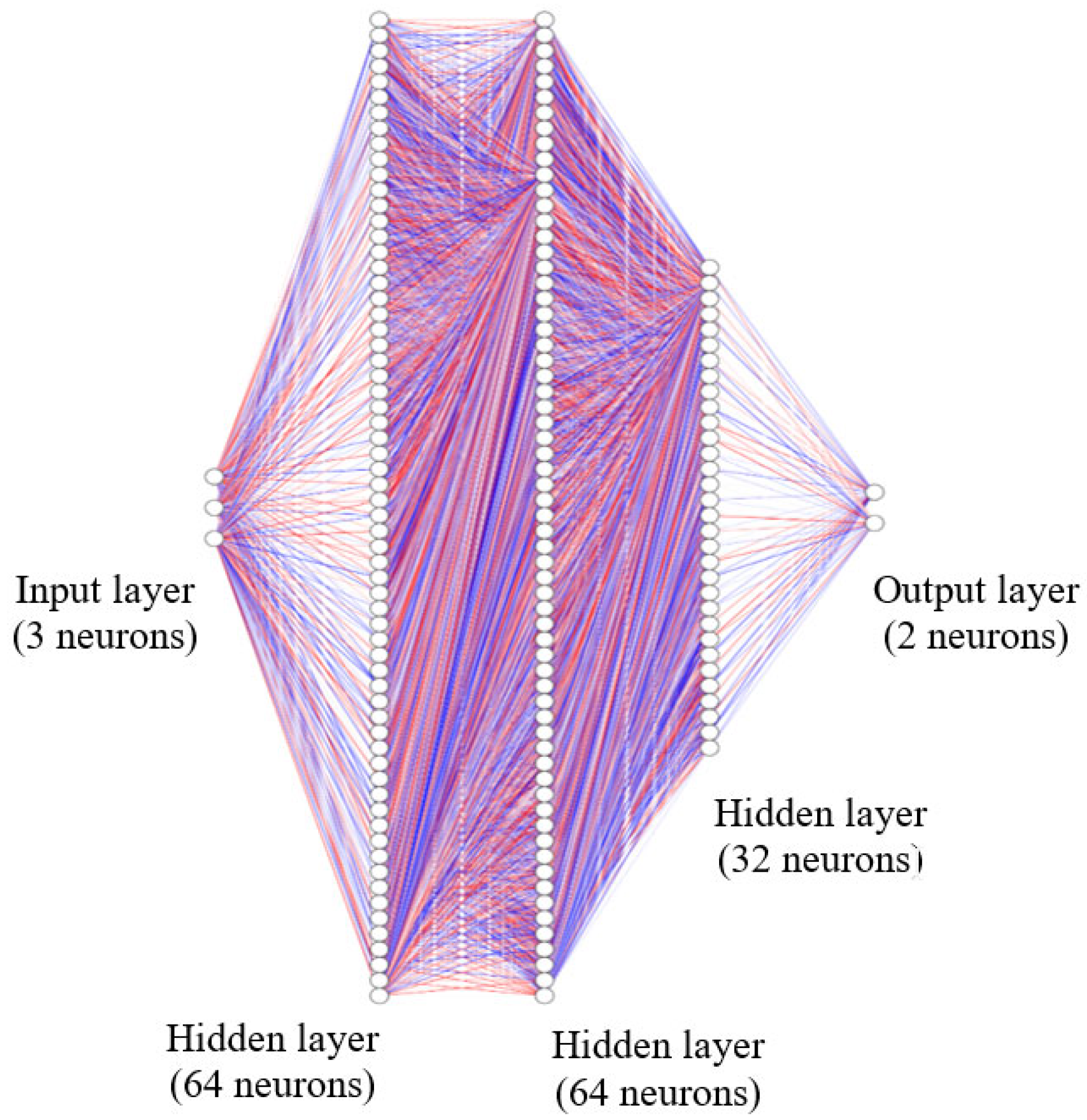
The neural network model was implemented using TensorFlow/Keras and consisted of a single input layer with three neurons (representing control error, measured temperature, and time), followed by two hidden layers with 64 neurons each, and a third hidden layer with 32 neurons, all using ReLU activation functions; see
Figure 6. The output layer comprised two neurons corresponding to the predicted values of the proportional gain (Kc) and the derivative gain (Kd). The model was trained using the Adam optimizer, implemented via TensorFlow/Keras (Google Inc., Mountain View, CA, USA), and the mean squared error (MSE) loss function, with a total of 200 training epochs and a batch size of 16. Prior to training, all input and output data were standardized using StandardScaler function from Scikit-learn (INRIA, Paris, France) to enhance learning efficiency and ensure numerical stability during optimization.
To enable real-time adaptation of the PID controller, a supervised learning approach using an ANN was adopted. The main objective was to train the model to predict optimal PID parameters (specifically Kc and Kd) as a function of the thermal process behavior over time, considering the control error and measured temperature as inputs. The integral gain Ki was kept constant throughout all test cycles and was therefore not included in the learning process, based on preliminary self-tuning experiments in which Ki showed minimal variation across configurations.
The dataset used to train the ANN was constructed from 8 experimental runs, in which multiple fixed PID configurations were applied to the system (see
Table 1). At each
time step, the configuration with the lowest control error was selected. This process is described in Equation (3).
where
is the control error associated with the
PID configuration at time
and
is the total number of tested configurations. From the selected configuration, the values
,
, the corresponding control error
and the measured temperature
were extracted and used to construct the dataset. The model’s input features consisted of the triplet:
while the target outputs were:
Before training, all features and target outputs were normalized using standardization (zero mean and unit variance). The transformation is defined by Equation (6).
where
and
are the mean of feature x and the standard deviation of feature x, respectively. This was applied to both input and output variables to ensure faster convergence and balanced training.
The neural network function approximating the nonlinear mapping is defined by Equation (7).
where
denotes the set of all network weights and biases.
The model was trained to minimize the MSE loss function, as defined by Equation (8).
where
is the normalized input at index
,
is the normalized target output vector at index
and
is the network prediction. The backpropagation algorithm with the Adam optimizer was used to update the weights and early stopping or validation monitoring was applied to avoid overfitting.
For the inference and inverse scaling, after training, predictions
from the network were converted back to their real-world values using the inverse transformation; see Equation (9).
where
and
are the mean of feature x and the standard deviation of feature x, respectively. This was applied to both input and output variables to ensure faster convergence and balanced training.
2.7. Real-Time Implementation of the Adaptive Controller
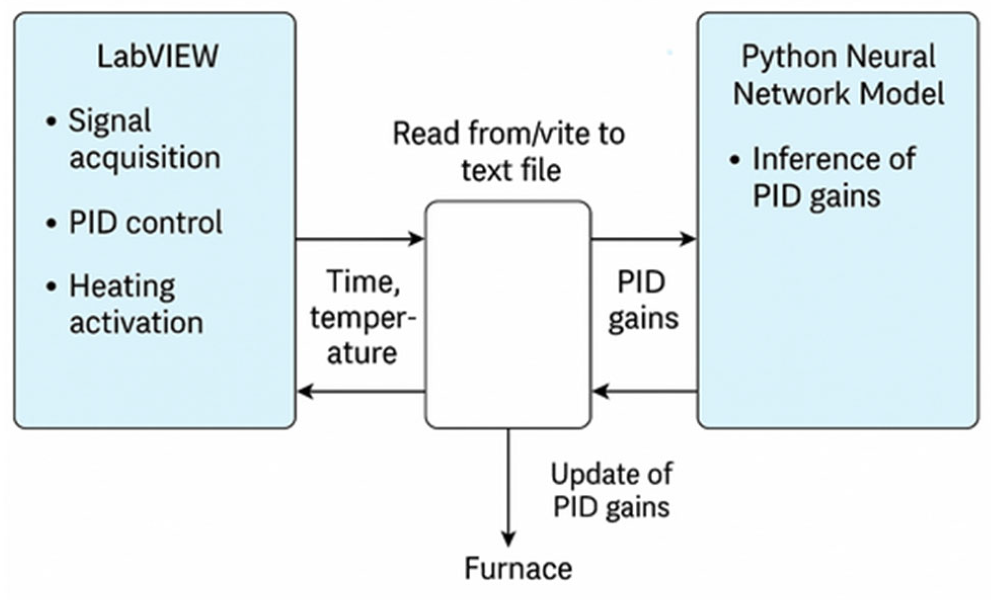
The real-time adaptive PID controller was implemented using LabVIEW and an NI USB-6009 data acquisition system from National Instruments. LabVIEW was responsible for temperature acquisition, PID control, and heating triggering. However, due to limitations in the native execution of Python within LabVIEW, the trained neural network was executed externally through a Python script. The communication between LabVIEW and the neural model was managed using a file-based data exchange protocol.
Figure 7 shows the communication scheme between LabVIEW and the neural network model. In this setup, LabVIEW retrieves the current process time and writes it to a text file. The Python script reads this input, loads the trained neural network model, performs inference to predict the optimal PID parameters, and writes the results back to the same file. LabVIEW reads the updated PID values and applies them in real time to the control loop.
Algorithm 1 shows the detailed step-by-step interaction, which outlines the operational logic underlying the adaptive control loop. The proportional and derivative gains (, ) are updated in real time, while the integral gain () remains constant throughout. This architecture allows adaptive control of the furnace without the need for direct Python-LabVIEW integration.
This hybrid structure allows for the dynamic adjustment of the proportional (Kc) and derivative (Kd) gains, while keeping the integral gain (Ki) fixed, based on insights gained during the auto-tuning phase. The selected approach effectively circumvents the need for direct LabVIEW-Python integration, offering a flexible and scalable solution for real-time adaptive control.
| Algorithm 1: Real-time PID adaptation using neural network and LabVIEW. |
Input: Process time t
Output: PID gains (Kc, Kd) |
| 1: | while control loop is running do |
| 2: | Acquiring process time t from LabVIEW control system |
| 3: | Execute external Python script with t as input argument |
| 4: | Python loads trained neural network model |
| 5: | Python normalizes input t |
| 6: | Predict PID parameters: [Ki, Kd, Kc, Error, Temp] |
| 7: | Save predicted values to output file (output_pid.txt) |
| 8: | LabVIEW reads output_pid.txt |
| 9: | Extract Kc and Kd from file |
| 10: | Update LabVIEW PID controller with new Kc and Kd |
| 11: | Waiting for next cycle |
| 12: | end while |
This implementation successfully decouples the neural inference from the primary control loop, ensuring that the system remains responsive and deterministic from the LabVIEW environment’s perspective.
3. Results and Discussion
In this section, the adaptive PID control based on neural networks was implemented. It was validated using experimental data obtained from the high-temperature furnace. The results show good agreement with the temperature setpoints defined by the computer, as indicated by the low associated error values in the results.
It is important to clarify that the term “real-time integration” in this work refers to a smooth real-time operation, where the PID gains are updated at each control cycle fast enough to satisfy the dynamic requirements of the thermal system. Although a real-time operating system (RTOS) was not used, ANN inference was performed via Python within a window of 0.0536 ms per cycle, which is negligible compared to thermal time constants (on the order of several seconds). The file-based exchange between LabVIEW and Python allows synchronous execution within a one-second control loop, maintaining a stable and responsive system for the intended application. This architecture provides a practical and adaptive solution for systems with moderate dynamic demands.
3.1. Neural Network Training
3.1.1. PID Controller Auto-Tuning Using MATLAB Simulink
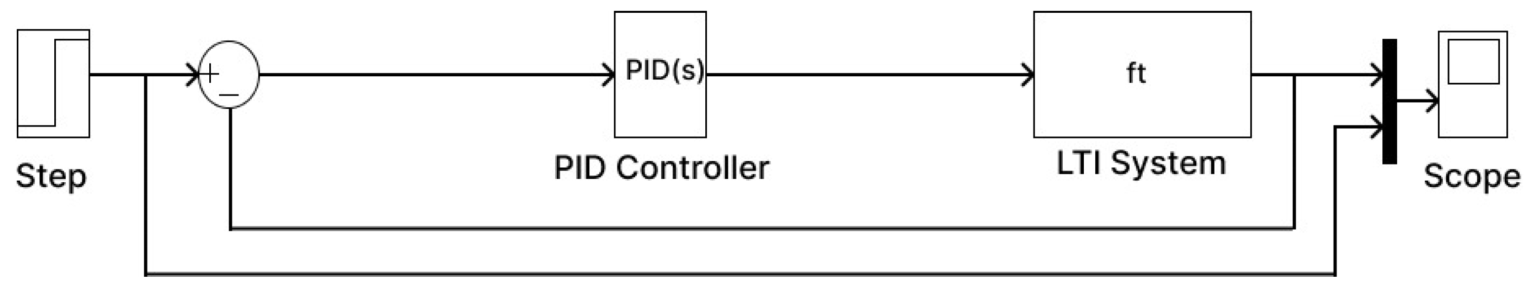
Subsequently, the PID controller coefficients were simulated and calculated using the Simulink tool in MATLAB, which provides a built-in PID auto-tuning function. This tool allows tuning based on predefined criteria such as maximum overshoot and settling time. A block diagram was constructed as shown in
Figure 8, integrating the furnace model and the PID controller. Based on this configuration, the PID Controller block’s auto-tuning function was used. This feature allows for interactive adjustment of the desired settling time while simultaneously generating automatically tuned values for the PID gains.
Eight datasets provided by this tool were used to train the neural network, enabling dynamic adjustment of the controller parameters in real time; see
Table 1.
3.1.2. Experimental Evaluation of Fixed PID Configurations for Neural Network Training
To generate representative data sets for neural network training, eight fixed PID configurations were experimentally tested in the high-temperature furnace (see
Table 1). Each configuration corresponds to a specific set of gains. For each test, the furnace was subjected to a standard thermal profile with defined set points, and the system response was recorded.
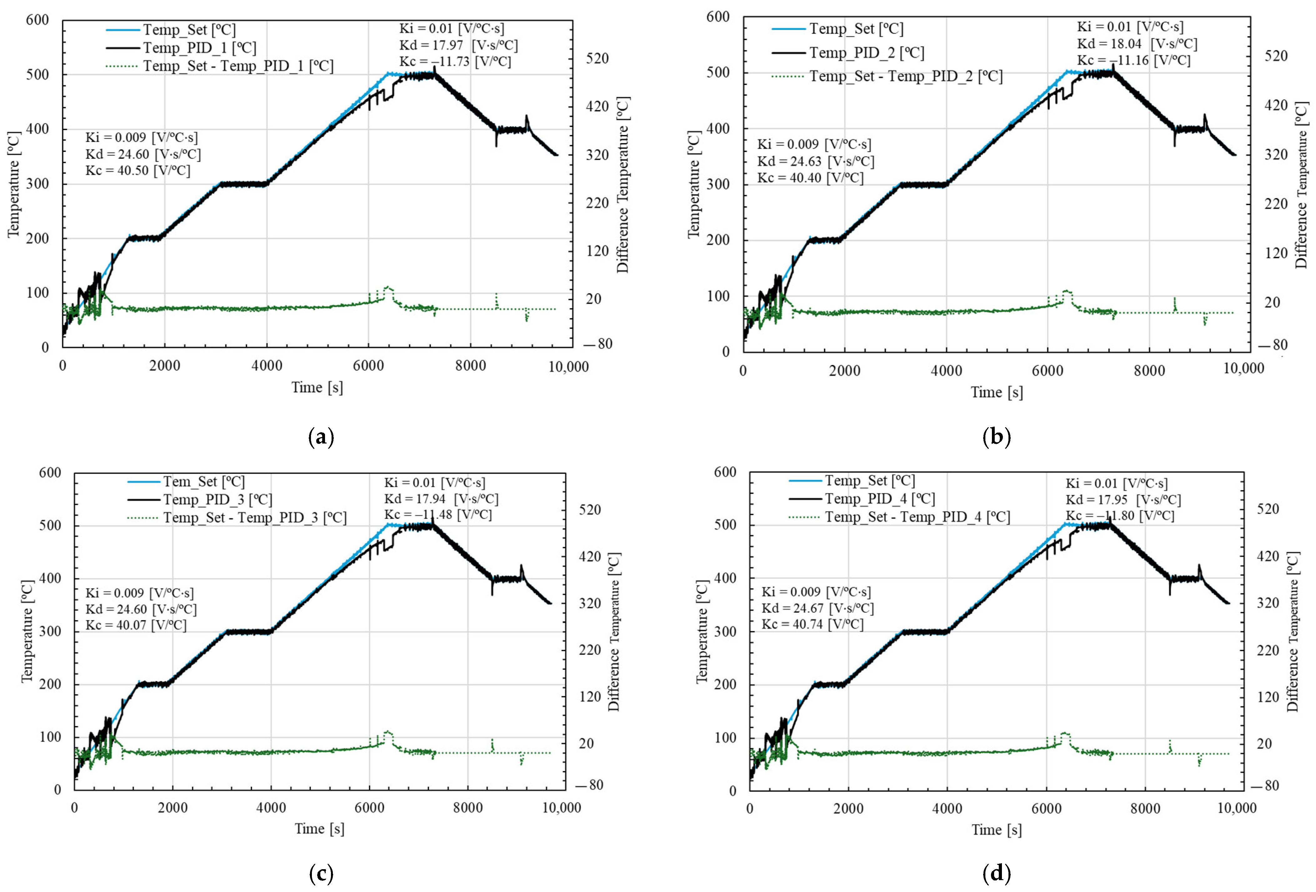
Figure 9 shows the results of four sets, where fixed PID gains were applied for the heating and cooling phases. The resulting temperature response and associated error were used as part of the training data set for the neural controller.
Figure 9 presents only the first four datasets. It can be observed that during the initial heating phase, the temperature curve struggles to stabilize, and the error is noticeably significant. In the first heating stage (up to approximately 1350 min), the system reaches a temperature of around 200 °C, where the greatest error differences occur.
In the third heating phase, discrepancies are also evident, particularly between seconds 6013 and 6733. Across all subfigures, the measured experimental temperature remains consistently lower than the setpoint defined by the computer.
During the cooling phase, temperature instability is also observed; however, there is no significant associated error. In these cases, the peaks of both the measured and setpoint temperatures tend to align closely.
These discrepancies, especially during heating, may be explained by the thermal inertia of the system, which causes a delay in the furnace’s temperature response. Additionally, the use of fixed PID parameters may not be optimal during transient phases, leading to modeling errors or insufficient gain tuning in the early stages of heating. The slower stabilization rate may also be influenced by energy losses, which were not considered in this study.
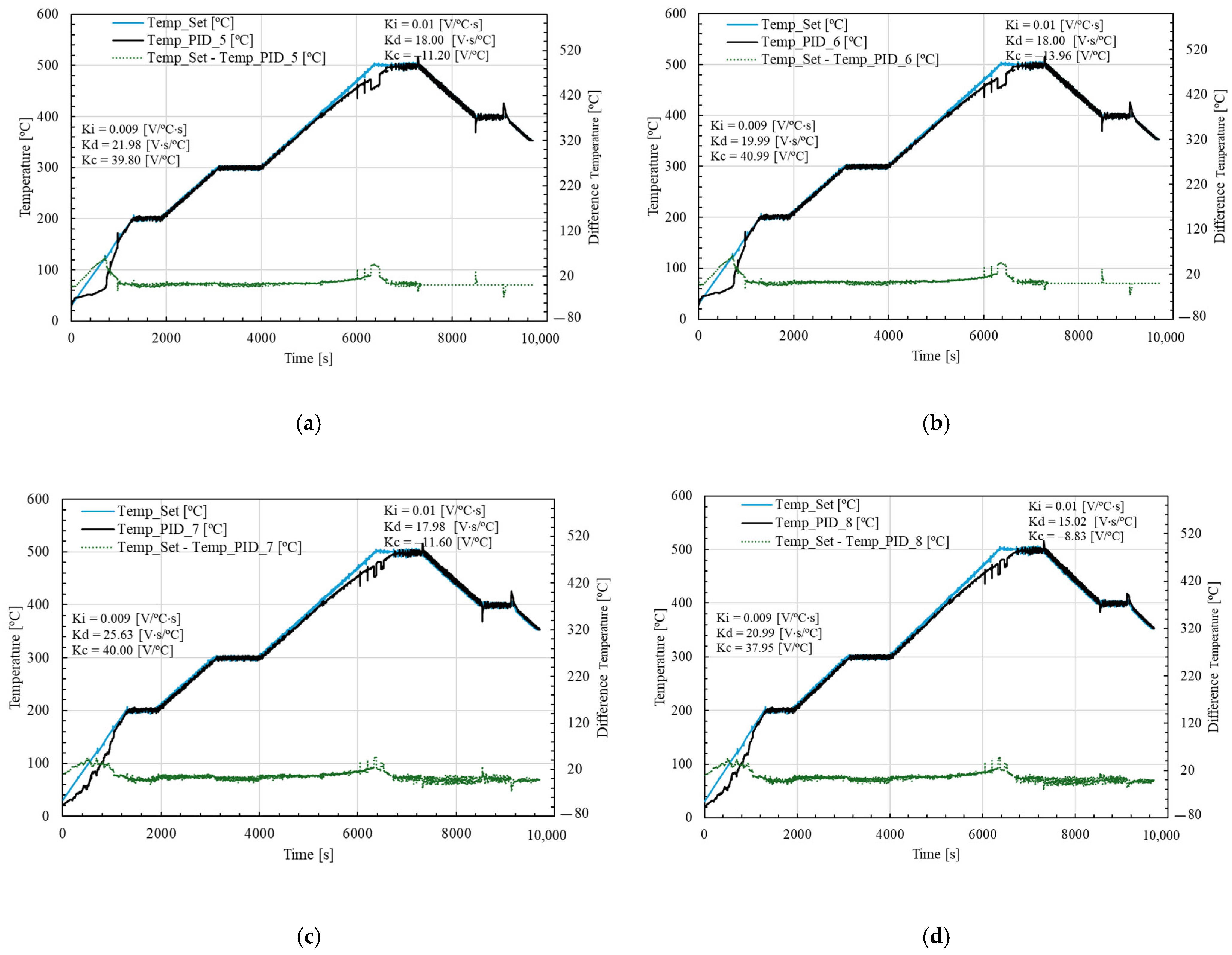
Figure 10 shows the remaining four datasets of temperature and error used for training the neural network. It can be observed that in
Figure 10a,b, corresponding to sets 5 and 6, the first heating phase exhibits a significantly lower error compared to
Figure 9a,b. This indicates that the PID parameters
and
used in sets 5 and 6 perform better during the initial heating stage. However, in the final heating phase, the error and discrepancies begin to increase, suggesting a degradation in control performance as the system approaches higher temperature levels.
In the cases of (c) and (d), corresponding to sets 7 and 8, a larger error margin is observed during the initial heating phase. Nevertheless, during the third heating stage (between seconds 6046 and 7158), a slight improvement in error behavior can be noted. Overall, these results confirm that the PID gains
and
have a strong influence during the heating phase, and in sets 5 to 8, the response shows noticeable improvements compared to the previous sets shown in
Figure 9.
The observed discrepancies, especially during the heating stages, may be attributed to the thermal inertia of the system, which delays the temperature response, and to the limited quantification of energy losses, which were not explicitly modeled in this study. These factors introduce dynamic effects that fixed PID parameters cannot fully compensate for, especially in transient conditions.
These experimental results will be used as training data for the neural network to enable dynamic and adaptive control.
3.2. Artificial Neural Network Training and Validation
Figure 11 shows the training and validation loss curves of the artificial neural network model over 200 epochs. The loss function used was the mean square error. It can be observed that both training and validation losses decrease rapidly during the initial epochs and tend to stabilize after approximately 50 epochs. The closeness between training and validation losses throughout the learning process indicates that the model generalizes well and does not suffer from overfitting. Small fluctuations in the validation curve can be attributed to variations present in the training data set and remain within acceptable limits.
The artificial neural network model was trained to predict the optimal PID controller parameters Kd and Kc based on three inputs, including control-associated error, temperature, and time. Past research [
5,
16,
22] shows the performance metrics for each predicted output, including mean absolute error (MAE), root mean square error (RMSE), maximum absolute error (MaxAE), integral absolute error (IAE), mean bias error (MBE) and coefficient of determination (R
2). The results show that the model achieves good predictive accuracy, with R
2 values of 0.9634 for Kd and 0.9990 for Kc, respectively. These values are summarized in
Table 2. The high R
2 values obtained for both results indicate that the ANN model can explain most of the variance of the optimal Kd and Kc parameters in the data set. The MAE and RMSE values are relatively low for both results, and the Maximum Absolute Error (MaxAE) values, although higher than MAE, remain within operating ranges that do not significantly affect the overall prediction performance. Although the IAE values for Kd and Kc appear numerically high, this is a direct consequence of the large number of validation samples (971). Normalized by the number of samples, the mean absolute error per sample corresponds exactly to the reported MAE values (0.3546 for Kd and 0.4084 for Kc), which are low relative to the output quantities.
Finally, MBE values close to zero indicate that the ANN model does not systematically overestimate or underestimate the predicted gains; consequently, one has an unbiased model.
3.3. Dataset Description and Inference Time Analysis
Table 3 shows the data set used to train and validate the artificial neural network model. The corresponding outputs are the optimal PID controller parameters Kd and Kc. These optimal gains were selected from a set of 10 candidate configurations per sample based on the minimum control error, ensuring that the ANN was trained with the most representative data points (see
Figure 9 and
Figure 10). A simple splitting strategy was employed to partition the data set:
Cross-validation techniques such as k-fold were not employed in this study to prioritize computational efficiency and focus on establishing a robust benchmark performance for the ANN model. A single random training/test split was con sufficient for the intended analysis. The inference time of the trained ANN model was evaluated to be over 1000 consecutive prediction cycles. The average inference time per prediction was 0.0536 ms. This extremely low inference time demonstrates that the model is suitable for real-time or near-real-time deployment scenarios, where it is critical to quickly update the PID controller gains based on evolving system conditions. The ANN was trained with Python 3.12 and TensorFlow (Google Inc., Mountain View, CA, USA) on a computer equipped with an AMD Ryzen 9 5000 series CPU (Advanced Micro Devices, Inc., Santa Clara, CA, USA), without GPU acceleration. Total training time was approximately 3 min, although training time may vary depending on hardware.
3.4. Sensitivity Analysis of Input Features
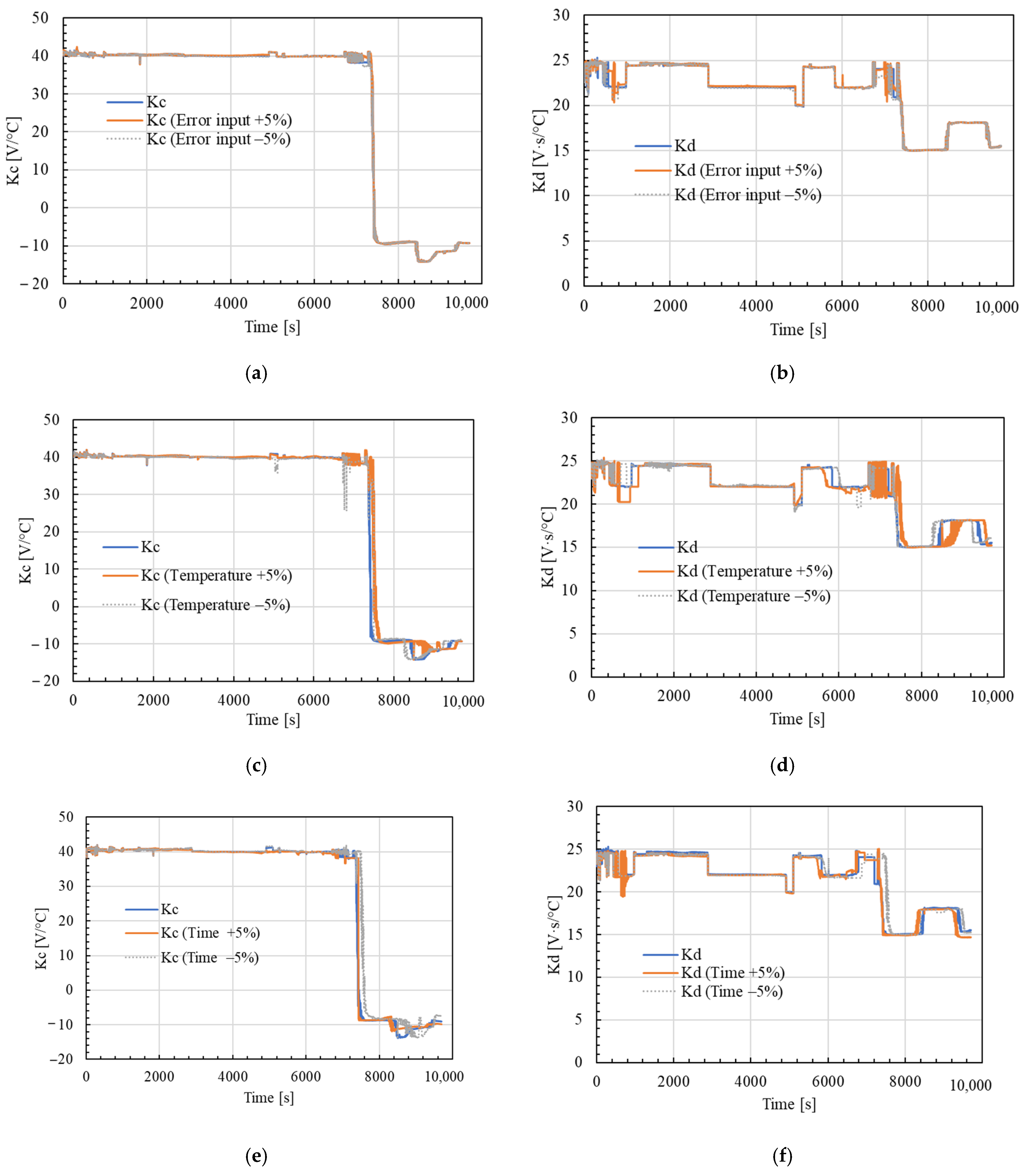
Figure 12 compares the neural network predictions for the gains Kc and Kd (blue solid traces) with the same predictions after perturbing each input variable by ±5% (green and red dashed traces).
In
Figure 12a,b, small variations in the PID error (input variable
) barely affect both gains; the ±5% curves remain close to the original prediction, indicating that the network does not overreact to noise in the PID error signal.
Figure 12c,d show similarly limited sensitivity to the measured PID temperature (
); appreciable deviations only appear in the transition zone around 7000 s, where the training data are sparser.
Finally,
Figure 12e,f show that the time coordinate t is the least influential input after perturbing the PID error input.
Overall, the six plots demonstrate that the neural network remains robust as long as small uncertainties in the three inputs are introduced. Residual sensitivity is restricted to dynamic transients where a steeper adaptation of the gains is, in fact, desirable.
3.5. PID Dynamic and Adaptative Control
Figure 13 illustrates the temperature regulation performance of the furnace using the adaptive PID controller powered by the trained neural network. In this phase, only the parameters
and
were adjusted in real time, while
was kept constant. This decision was based on observations during the autotuning phase, where the integral gain showed minimal variation across all test sets, indicating a low sensitivity to system dynamics.
The results show that the experimental temperature closely follows the setpoint curve, with minimal steady-state error. During the initial heating phase, between 0 and approximately 470 s, some deviations are present; however, after this point, the control system stabilizes and maintains good performance. Unlike the irregular responses seen in the first heating phase of
Figure 9 and
Figure 10, the temperature curve in
Figure 13 exhibits a much smoother and more linear behavior during this stage, particularly when compared to the response in
Figure 10, where the early heating trend was notably nonlinear. In the third heating phase (specifically between 6217 and 6608 s), some discrepancies persist, yet they are significantly reduced compared to the datasets used to train the neural network. This demonstrates the neural controller’s ability to generalize beyond the training data and adapt to new operating conditions effectively.
Furthermore, in the cooling phase, the system maintains stable behavior, and the characteristic temperature peaks observed in previous figures with fixed PID control are no longer present. The setpoint and measured temperature curves remain well aligned throughout this phase, indicating that the adaptive controller avoids oscillations. Overall, these results validate the effectiveness of the proposed neural network-based adaptive PID control strategy (using fixed ) in achieving accurate, stable, and responsive temperature regulation in high-temperature thermal systems.
Table 4 compares the performance of the proposed dynamic PID controller trained using an artificial neural network with eight fixed PID configurations under identical thermal conditions, which were used for neural network learning previously.
The strategy named Temp_PID_Dynamic achieved the lowest overshoot percentage (41.12%) among all the controllers tested, significantly outperforming the fixed configurations, which consistently showed values of about 53.3%. This result indicates a smoother control response with reduced overshoot, which is beneficial in thermal applications where overheating can compromise safety or efficiency.
The dynamic controller also yielded a slightly lower MAE (5.08 °C) and RMSE (9.41 °C) than all the fixed strategies, except for Temp_PID_3 and Temp_PID_4, whose errors were slightly smaller but have larger overshoot compared to the proposed dynamic PID. These results demonstrate that the ANN-PID controller reduces overshoot and maintains competitive tracking accuracy, validating the potential of data-driven adaptive control strategies in temperature regulation systems.
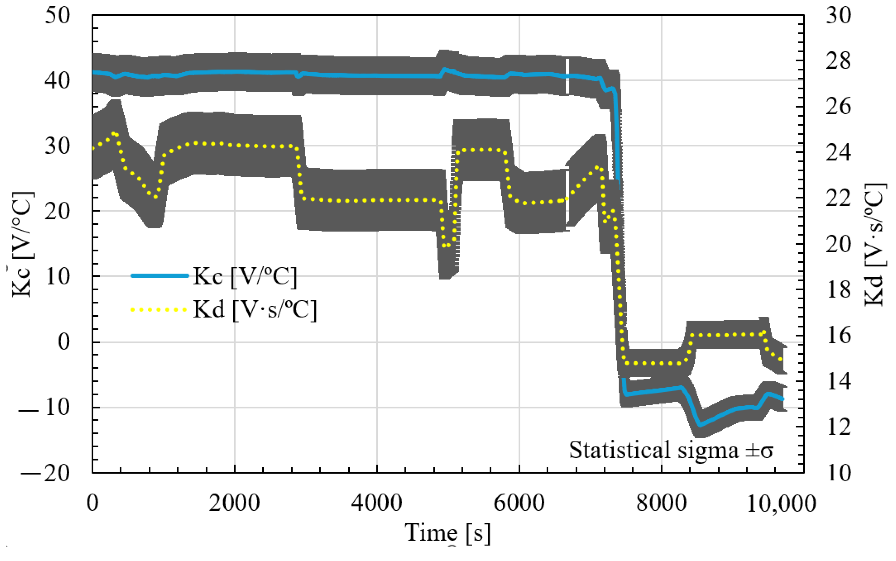
Figure 14 shows the evolution of the proportional (
) and derivative (
) over time, tuned by the neural network-based adaptive PID controller. These parameters were updated in real time as a function of the furnace thermal behavior and dynamic conditions.
During the first 7000 s, Kc remains within relatively stable ranges while Kd varies within the values 19.99 and 24.6 , with slight adjustments to adapt to the different heating and holding phases.
However, after about 7500 s, there is an abrupt change in both parameters. It drops rapidly and even takes negative values, while it decreases to about 14–16 for Kd and −12.7 to −8.13 for Kc, respectively. This behavior corresponds to the cooling phase, where the control strategy needs to reverse or attenuate its action due to the different thermal dynamics of heat loss versus heat input.
This abrupt transition demonstrates the ability of the neural network to distinguish between heating and cooling conditions and adapt the controller parameters accordingly. Overall, this plot confirms that the neural controller effectively modulates the PID gains in real time, responding to changes in system behavior and optimizing the control effort at different phases of operation.
Table 5 shows a summary of the statistical behavior of the Kc and Kd values generated by the neural network during real-time operation. In this, the mean and standard deviation (σ) of each parameter throughout the control phase can be seen.
In the heating mode, the mean values of the gains were Kc = 40.3564 [V/°C] and Kd = 22.8523 [V·s/°C], with standard deviations of 3.8330 and 1.4136, respectively. These values reflect relatively stable behavior with moderate variability. During cooling, the regulator showed lower gains with mean values of Kc = −9.1833 [V/°C], Kd = 15.4150 [V·s/°C], and respective standard deviations of 1.7316 and 0.6643. This reduction is expected, since thermal inertia and control sensitivity usually differ between the heating and cooling phases.
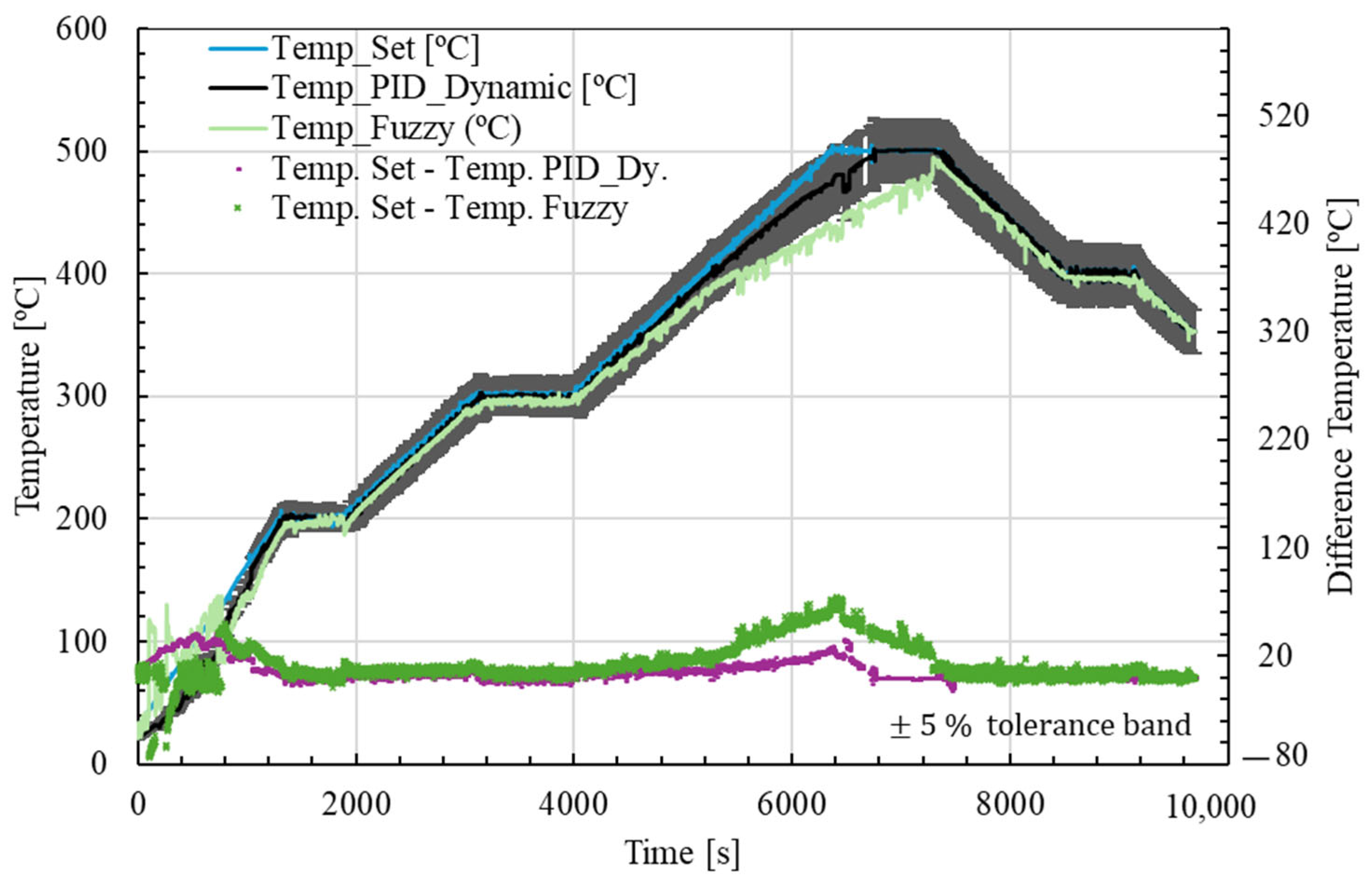
Figure 15 shows a further comparative analysis between the neural network-based adaptive PID controller and a fuzzy logic controller. Both controllers were tested with identical thermal setpoint profiles.
The temperature setpoint is shown in blue, while the system responses with adaptive PID control and fuzzy control are represented in black and green, respectively. The associated control errors are shown in magenta (PID) and light green (fuzzy). The adaptive PID controller shows superior tracking performance throughout the cycle, with lower steady-state error and faster stabilization during warm-up phases. In the third heating phase and in the cooling phase, the fuzzy controller shows larger deviations from the setpoint, while the PID controller maintains better alignment.
These results indicate that the neural network-based adaptive PID controller provides better generalization and control accuracy than the fuzzy controller for this thermal process. However, both controllers achieve acceptable performance, validating the potential of intelligent control strategies for complex thermal systems.
Table 6 presents a comparative analysis between the ANN-based dynamic PID controller and a fuzzy logic controller in terms of control accuracy and performance metrics. The dynamic PID controller achieved significantly better performance, with an MAE of 5.08 °C and RMSE of 9.41 °C, outperforming the fuzzy logic strategy, which showed much higher error values (15.27 °C MAE and 22.64 °C RMSE). This improvement indicates a more accurate tracking of the setpoint temperature throughout the cycle.
In addition, the overshoot percentage was also lower for the dynamc PID (41.12%) than for the fuzzy controller (48.04%). This shows that the neural network-based control strategy provides higher accuracy by improving stability and reducing the risk of overshoot during transient phases.
4. Conclusions
This work presents the design, implementation and validation of an intelligent control system for a high-temperature furnace for heat treatment with an approximate accuracy of ±10 °C error. The control system integrates custom designed electrical, electronic and control subsystems, providing full automation and acceptable temperature regulation. The proposed architecture enables the execution of advanced thermal processes, such as annealing, with high precision, while allowing user-defined heating and cooling ramps.
An adaptive PID controller based on a neural network has been developed and experimentally tested. The proportional controller () and derivative () were tuned in real time based on the system behavior, while the integral gain () was kept constant due to its low sensitivity over the entire operating range. The neural network was trained using eight sets of PID experiments, each of which selected the configuration with the lowest control error. This training strategy allowed the controller to generalize across different phases of the thermal cycle, compensating for nonlinearities and thermal inertia effects.
Experimental results show that the adaptive PID controller achieved superior performance to traditional fixed-gain PID control and fuzzy logic control. The adaptive controller showed faster response time, lower steady-state error and more stable behavior during critical phases, such as the initial and third heating ramps. In addition, the adaptive controller was able to eliminate the temperature spikes observed during the cooling phase, a common problem in conventional systems. Although the fuzzy controller has also been tested, it had larger error margins during heating transitions. In contrast, the neuron-based PID control system offers a flexible, model-free approach that could be retrained with new data sets to adapt to system changes, without the need for manual re-tuning.
Although the adaptive PID controller significantly improved temperature regulation throughout the thermal cycle, some limitations remain. During the initial warm-up phase, the temperature error between the adaptive controller response and the setpoint remains non-negligible. This discrepancy is likely associated with the thermal inertia of the system, fluctuating initial conditions, and unmodeled energy losses inherent in the furnace structure. Future work should incorporate these factors into the control model, either through physical modeling, additional sensor inputs, or enhanced neural network functions, to further minimize transient error and improve early-stage performance. Consideration should also be given to expanding the input space of the neural network to include variables such as rate of temperature change or heating phase indicators. The incorporation of these variables could also increase the accuracy and adaptability of the control system, especially in the first heating phase.


 ,
, 


