Abstract
There is increasing penetration of photovoltaic (PV) systems into modern power grids; however, existing centralized communication architectures for PV stations often suffer from high latency and poor scalability, and the synchronization and coordinated control of multi-inverter clusters at millisecond timescales remain unresolved challenges. Hence, this paper proposes a distributed communication-based framework integrating multi-inverter synchronization and dynamic power allocation for rapid power regulation in PV stations. The architecture employs decentralized control logic to achieve the real-time synchronization of inverter clusters, eliminating reliance on centralized controllers. A dynamic power allocation algorithm, embedded with adaptive droop characteristics, optimizes active power distribution across inverters while minimizing transient overshoot. Experimental validation confirms the efficacy and operational advantages of the proposed communication architecture and power allocation strategy.
1. Introduction
With the increasing shortage of traditional fossil energy sources, developing new power systems, mainly based on new energy sources around the world [1,2], especially the new power generation technologies represented by photovoltaic (PV) power generation, are developing rapidly. But PV systems lack the rotating mechanical components inherent to synchronous generators, rendering them incapable of supplying effective inertia or supplemental power support to the power system. These deficiencies critically impact key operational parameters, including active power balance, reactive voltage regulation, transient stability, power angle stability, and protection schemes, posing significant challenges to power system operation and control [3,4]. Furthermore, the increasing digitalization and reliance on sophisticated communication networks for controlling these distributed PV systems introduce new considerations regarding interoperability, real-time performance, and cybersecurity, which must be addressed for resilient grid operation [5]. Consequently, advancing research into PV control technologies has become a critical priority [6].
Existing control strategies for the PV system can be categorized as maximum power point tracking (MPPT) and flexible power point tracking (FPPT) [7,8,9]. MPPT enables the tracking of the maximum output power of PV. Moreover, the MPPT control problem can be formulated as an optimization problem by developing a mathematical model of the PV system, thereby facilitating better control [6]. In [7], the particle swarm optimization algorithm was introduced into the MPPT control of the PV system to decentralize the initial positions of the particles to locate at the possible peak point voltages, which reduces the risk of falling into the local extreme points. And ref. [8] used an improved bat algorithm for the MPPT control of the PV system, and introduced Levy flight on the basis of the bat algorithm to make the algorithm able to jump out of the local optimum quickly. An MPPT control strategy based on the memetic salp swarm algorithm was proposed in [9], which introduced the cultural gene algorithm into the memetic salp swarm algorithm and effectively improved the local search capability of the original algorithm. To compensate for the defects and shortcomings of single-control methods, many studies have proposed control strategies for hybrid MPPT [10,11,12]. Although most of the hybrid control methods have better control effects, they have higher complexity and are not easy to realize. On the other hand, when the PV system is perturbed, it will immediately make a passive or active response in an attempt to offset or weaken the effects of the perturbation and try to maintain the system’s power angle, frequency, voltage, etc., within a permissible range, which poses a new challenge for the transient stability control strategies of the PV system [13]. Based on the traditional control strategy of the PV system, the rapid power control technology can respond to perturbations in transient time scales and reduce the amount of machine and load cuts. However, the FPPT control is a control method that can realize any power output at the maximum power point and below, balance the energy relationship between the PV, energy storage, and loads, and is increasingly replacing the MPPT control method [14]. An adaptive FPPT algorithm was proposed in [15], which adaptively adjusts the voltage step according to the dynamic and steady-state conditions in which the system is located. Ref. [16] proposed an FPPT control method based on the maximum power curve, which utilized the maximum power curve information of the PV characteristics to approximate the reference voltage value corresponding to the reference power. This response aims to maintain system parameters—such as power angle, frequency, and voltage—within permissible limits, but it inherently limits their ability to supply active or reactive power support to the grid during faults. If overcurrent or overvoltage conditions are detected, inverters may initiate high- or low-voltage ride-through protocols, reduce the active power output, or disconnect entirely from the grid. Such actions result in a sudden cessation of power output, imposing secondary power imbalances that adversely affect emergency power control and grid stability management systems [17]. Moreover, as these control systems become more interconnected, ensuring their cybersecurity against potential threats is crucial for maintaining grid integrity [18]. Consequently, developing rapid power control methods for photovoltaic systems at a transient timescale and enabling their active participation in grid frequency and voltage regulation enhances power grid operational stability [19,20,21].
More importantly, existing research on PV systems in power grid transient control primarily focuses on frequency regulation in single-machine and single-station systems, virtual synchronization-based frequency control, and microgrid applications. Studies on rapid power control strategies for PV stations remain limited. Ref. [22] proposed a hardware optimization method for inverters, which facilitated the fast reactive power response of multi-machine paralleled inverter units in a microgrid system, but it did not address the rapid regulation of new energy sources at the system level. Ref. [23] provided an experimental test study in the northwest grid for the individual fast frequency response of the PV inverters, realizing the individual inverter’s second-level primary frequency regulation power response, but this is far from the speed requirements. Ref. [24] studied the technology of the fast response of the active power of the PV system under the demand of primary frequency regulation of the power grid, and there existed much space to improve the power response speed of the individual inverter, and due to the influence of communication delays, this method cannot achieve the rapid power control of PV systems at the power station level. Recent advancements in areas such as decentralized consensus protocols and edge computing offer promising avenues to address these limitations by enabling more resilient coordination and faster local decision-making for inverter clusters. However, comprehensive frameworks that effectively integrate these emerging technologies for station-level, millisecond-timescale rapid power control, while also considering high-speed communication standards like IEC 61850-90-7 for enhanced interoperability and robust cybersecurity measures, are still under active investigation.
In summary, the rapid power control of PV stations faces the following two challenges:
Existing research lacks a comprehensive framework for coordinating multi-inverter clusters in PV stations at millisecond timescales. The autonomous regulation capability of individual PV stations is constrained by communication latency and the absence of a systematic coordination mechanism, often without fully leveraging the potential of decentralized control paradigms (e.g., consensus-based approaches) or high-performance, standardized communication architectures (e.g., compliant with IEC 61850-90-7 principles), leading to a suboptimal transient response and stability margins.
Current research on transient stability control strategies in photovoltaic systems exhibits notable limitations, particularly regarding rapid power control mechanisms. The absence of fast power regulation functionality in system control architecture, potentially exacerbated by the lack of localized intelligence (which could be enhanced by edge computing) and unaddressed cybersecurity vulnerabilities in increasingly connected systems, significantly constrains dynamic response capabilities during grid transients. Furthermore, while the integration of distributed energy storage systems (DESSs), particularly battery energy storage systems (BESSs), is increasingly common in modern PV stations to enhance flexibility and provide ancillary services like improved frequency regulation, this study primarily focuses on the rapid power control capabilities achievable through the coordinated control of PV inverters themselves. The synergistic operation with DESSs, including their role in providing sustained up-regulation reserves, represents an important avenue for future research, building upon the foundational control architecture proposed herein.
To enhance rapid power control in PV stations, an efficient communication architecture and an equipment-level power allocation strategy were developed. The proposed layered relay communication framework, which aligns with the principles of distributed control and facilitates rapid information exchange akin to the goals of high-speed communication standards, significantly reduces intra-station latency. While this work primarily focuses on the communication and control logic, its architecture provides a foundation for the future integration of advanced decentralized consensus algorithms, edge intelligence, and comprehensive cybersecurity protocols. Building on existing rapid power control systems, an upgraded power adjustment strategy was formulated, incorporating an optimized PV inverter response scheme. Simulations demonstrate that the proposed architecture and allocation strategy ensure millisecond-level coordination and consistency in output power across all station equipment, effectively addressing grid demands for active and reactive power balance while improving the PV station’s rapid power response capability.
The remainder of this paper is structured as follows: Section 2 details the communication architecture design for PV stations; Section 3 outlines the principles of rapid power control of the PV equipment; Section 4 presents the intra-station power allocation strategy; Section 5 and Section 6 provide the simulation results and conclusions, respectively.
2. Communication Architecture for Rapid Power Control of PV Stations
2.1. Power Control Flow for PV Stations
The power control system of a photovoltaic station is primarily composed of an automatic generation control (AGC) system and an automatic voltage control (AVC) system, both of which are deployed at the substation level. These systems coordinate the operation of PV inverters, static var compensators (SVCs), static var generators (SVGs), and other reactive power compensation equipment. Together, they form the foundational infrastructure required to manage the station’s real and reactive power output, ensuring compliance with grid codes and operational reliability. The overall system architecture is designed to provide centralized control over distributed devices, as illustrated in Figure 1.
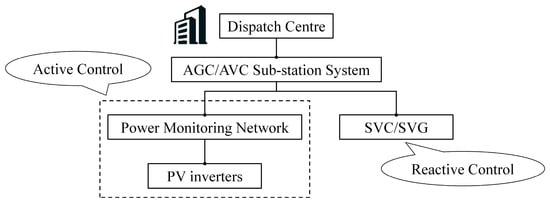
Figure 1.
Power control flow for PV stations.
Despite the structural integration of the AGC and AVC systems, there are critical limitations that hinder their responsiveness, particularly under dynamic grid conditions. Notably, the AGC/AVC platforms typically operate on non-real-time operating systems, which introduce latency in command execution and data processing. Furthermore, the communication protocols employed between the AGC/AVC systems and field devices—such as PV inverters and reactive power compensators—are often based on legacy standards or bandwidth-limited channels, resulting in significant delays during information exchange and control signal transmission.
These combined factors lead to an overall control latency that is generally in the order of seconds. While this may be sufficient for slow-changing operational scenarios, it is far from adequate in situations requiring rapid responses, such as grid emergencies, fault ride-through events, or transient voltage fluctuations. Under such conditions, the slow response of the AGC/AVC system becomes a bottleneck, making it difficult to meet the stringent requirements imposed by modern power systems for fast frequency regulation, voltage stability, and dynamic dispatch coordination.
2.2. Communication Architecture for Rapid Power Control
To address the deficiencies in the existing strategies for power control in the PV power stations, combined with the benefits of the stability control system in transient control and the demand for the rapid regulation of PV power, this paper proposes a novel communication architecture of the rapid power regulation system for PV, which is shown in Figure 2. This architecture is fundamentally designed to achieve low-latency, high-reliability data exchange, essential for sub-second control responses. By establishing direct communication pathways and minimizing intermediate processing layers, the proposed architecture aims to significantly reduce the end-to-end communication delay typically encountered in conventional, hierarchically layered SCADA systems, thereby facilitating the rapid power adjustments discussed in this work.
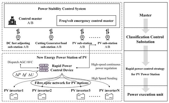
Figure 2.
A novel communication architecture for the rapid power control of PV stations.
First, the stability control system of the grid is used as the control master, and commands are relayed layer by layer through the stability control transmission. Secondly, the rapid power decomposition and communication of the whole power station is sent down by the rapid power control device in the PV power station. Finally, the rapid power regulation and control are quickly received and executed by the PV inverters.
The primary aim of this method is to substation the conventional operational mode of the power stability control system, which is characterized by “tripping off the entire station” in PV power stations. This is achieved through the rapid regulation of power, either by decreasing power or increasing it. The intended outcome is a decrease in load shedding, with the ultimate goal of eliminating it entirely, and a reduction in generator tripping, again with the aspiration of complete elimination. The objective is to meet or even surpass the power regulation response speed of 200~300 ms mandated by the power system. At present, the power stability control system achieves this speed through the execution of direct tripping and shedding in reaction to perturbations or malfunctions.
According to the design principle of layering, partitioning, and rotation, the rapid power control system for PV can be divided into two primary layers: the power stability control system layer and the PV power station layer. In particular, the stability control system layer, as the first layer, which includes (1) the station layer of the stability coordination control master, (2) the conventional generator tripping load-shedding substation, (3) the DC regulation substation/slave station, (4) the classified control layers, which include the PV renewable energy substation/slave station, etc. And then, the second layer is the renewable energy station, which includes the renewable energy rapid power control devices of the station and power control execution units, including PV inverters.
According to the above architecture, the PV station’s rapid power control should be required to obey the following control flow:
Step 1: Based on the voltage and current signals of the high-voltage side of the grid-connection point, use the real-time tracking method to collect the changes in the voltage and frequency of the grid-connection point.
Step 2: Based on the power index of the dispatching master station, calculate the corresponding total reactive power or active power regulation in real time for the overrun voltage or frequency (PV power stations must reserve spare capacity for frequency regulation to realize active up-regulation).
Step 3: Based on the online state of the PV inverters and the power regulating capacity, develop strategies and send out real-time reactive power or active power remote control commands.
Step 4: The fiber-optic ring network forwards real-time telecontrol commands to the PV inverter side, and the PV inverters respond to the telecontrol commands in real time and perform power regulation.
The results of the regulation are tracked by rapid power control devices, resulting in a closed-loop power regulation process.
3. Rapid Power Control Technology for PV Stations
3.1. Rapid Power Control and Regulation Algorithm
The rapid power control of the PV system can be mainly divided into two parts: active power control and reactive power control.
The active power control is achieved as follows: First, remote control commands are sent to the inverter communication board via the PV zone monitoring network, and then to the inverter actuator board, which drives the insulated gate bipolar transistor (IGBT) to respond to the power. The overall response time of the communication link between the AGC and inverters is on the second level without optimization. On the basis of the AGC system of the PV power station, adding the active-frequency sag control of the PV power station can realize the primary frequency control function of the PV power station.
Reactive power control uses inverters combined with capacitors or dynamic var compensator devices for a reactive power response. Among them, dynamic var compensator devices are mainly responsible for completing transient voltage support and steady-state reactive power regulation, and when its reactive power capacity is insufficient, it adopts inverter auxiliary regulation for reactive power support.
3.1.1. Active Power Control of PV Station
The rapid power control system participates in the frequency response of the system by regulating the active power, which is achieved by means of a sag control strategy as shown in Figure 3. And is the rated power, is the initial value of the active power, is the percentage of the increase in the output of the PV power station from frequency regulation that is not larger than the rated power under downward frequency perturbation, is the percentage of the reduction in the output of the PV power station from the frequency regulation that is not larger than the rated power under upward frequency perturbation, and is the minimum power percentage for the active power regulation of the PV power station under upward frequency perturbation. is the deadband value for the rapid frequency response with upper and lower limits and , respectively.
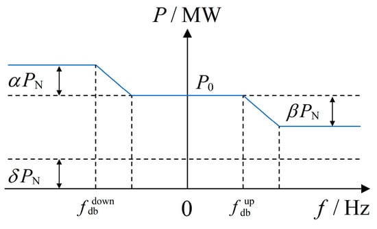
Figure 3.
Frequency sag characteristics of the PV station.
After calculating the total active regulation capacity by combining the primary frequency regulation parameters of the PV power station, the system frequency fluctuation, and the frequency sag characteristics, the information on the inverter side must be quickly collected, mainly including the current active power, the inverter capacity, and the inverter status. Considering that most of the inverters adopt the MPPT algorithm [25], they can only operate with limited power without reserving the frequency regulation backup. However, in this paper, we can reserve the frequency regulation backup for the PV power station and cooperate with a sample inverter (predicting the upper limit of the inverter’s active power) or appropriately increase part of the energy storage to complete the active up-regulation.
For the case of upward frequency perturbation, the active regulation is calculated according to the frequency sag characteristic, and the active target value of the k-th inverter can be expressed as follows:
where is the current active power of the k-th inverter, and is the current active power lower limit of the k-th inverter, representing the minimum permissible output power for the inverter, or a strategically set reserve margin for downward regulation. is an equal proportionality factor, Num denotes the number of inverters in the normal operation of the PV power station, and is the amount of active power regulation.
Similarly, for the case of downward frequency perturbation, the active regulation is calculated according to the frequency sag characteristic, and can be calculated as
where is the current active power upper limit of the k-th inverter, typically corresponding to its maximum available power under current operating conditions. is the calibration parameter intended to account for potential variations in the actual power generation capabilities among different PV arrays or inverter units. It is set to 1 by default, assuming uniform performance across the participating inverters.
3.1.2. Reactive Power Control of PV Station
The rapid power control system participates in the voltage response of the system by regulating reactive power, specifically calculating the amount of reactive power regulation of the PV power station in real time according to the grid-connected point voltage, the system impedance parameters, and the target voltage, power factor, or reactive power target value of the grid, and then decomposing it according to the inverter reactive power margins.
Considering the difference in the inverter models and capacities in the PV power station, assume that the maximum absorbed reactive power of the k-th inverter is and the maximum emitted reactive power is . Set the reactive power required to be absorbed and emitted as and , respectively; then, the target value of the reactive power output of the inverter can be indicated as follows:
where is the current reactive power output of the k-th inverter, k = 1, 2, …, Num, and and are the percentages of the reactive power output emitted and absorbed by the inverter, respectively.
When the system is initialized, the inverter group works according to the power factor of 1, i.e., . When the system needs reactive power support, in order to avoid some inverters fully generating while others are in reactive power no-load imbalance, this paper adopts the equal proportional balance distribution algorithm to assign the target value of reactive power regulation [26,27]. The algorithm can balance the heat dissipation of the inverter on the one hand, and on the other hand, it can reduce the number of iterations of reactive power regulation and shorten the closed-loop time from dynamic to the steady state.
3.2. Rapid Power Control Technology for PV Stations
Within the field of power electronics, the PV inverter, a key device based on IGBTs, demonstrates its excellent performance in terms of fast response. Especially in PV systems, PV inverters have a significant advantage in rapid power regulation due to the absence of rotating inertial mechanical parts in their structure. It should be noted that in certain inland areas of China, the installed capacity and power generation of PV have already exceeded that of wind energy. Based on this, this section addresses the rapid power control technology for PV power stations.
Currently, the AGC systems of the PV power stations have limitations in rapid power control, and there is an urgent need to develop a novel rapid power control device that can communicate and interact with hundreds of PV inverters in an efficient way. As shown in Figure 4, the device is responsible for receiving power adjustment commands (including both upward and backward modes) from the higher-level stability control system (or dispatch center, AGC/AVC station, etc.) and feeding back the current total adjustable power range of the PV power station. At the lower level, the device coordinates with numerous PV inverters in the power station via high-speed communications for centralized control and cluster scheduling.
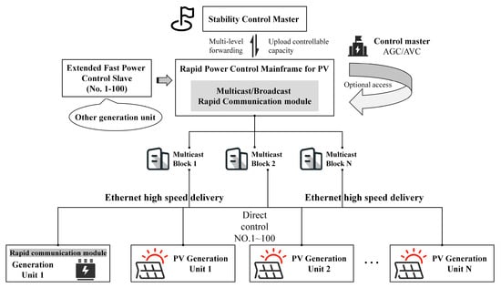
Figure 4.
A novel rapid power control technology for PV stations.
Considering the difference in the size of the PV power stations, for most small- and medium-sized PV power stations (i.e., those with an installed capacity of up to 50 MW), a single rapid power control master is generally sufficient to satisfy their operational requirements. However, for larger-scale PV power stations with an installed capacity of more than 100 MW, it is recommended to adopt a master–slave multi-machine structure, as shown in Figure 4, in order to improve the reliability of the system and the flexibility of power regulation.
In this section, an Ethernet-based multicast or broadcast protocol communication mechanism is proposed as a bridge for information interaction between a rapid power control device and a large number of PV inverters, as shown in Figure 4. The device can effectively control a large number of inverter units quickly by using a “one-to-many” sending mechanism and a high-importance communication strategy that does not require acknowledgement. This approach is conceptually designed to minimize communication overhead on the master controller and reduce network congestion by eliminating acknowledgement traffic from numerous inverters, which is particularly beneficial in large-scale PV stations with hundreds or thousands of inverters. The choice of modern Ethernet, especially when implemented over a dedicated fiber optic network typically used within PV power stations, offers high bandwidth potential and inherently lower latency compared to older serial or fieldbus technologies. The multicast/broadcast nature further reduces the source load as a single message and can reach multiple destinations, contributing to the efficient use of network resources. Since this transmission method does not require acknowledgement from the inverters, it not only solves the problem of communication blockage caused by simultaneous acknowledgement from multiple inverters but also reduces the communication computational burden caused by a large number of acknowledgement messages on the common receiving master.
To manage the impact of transient communication disturbances, such as packet loss, the control logic at the inverter level incorporates a hold-last-valid-command mechanism. If a new control command is not received within an expected timeframe , the inverter continues to operate based on the last successfully received and validated command :
This provides a degree of resilience against intermittent packet loss. For more persistent communication disruptions, such as a localized network outage isolating a group of inverters, a fail-safe operational mode is triggered. This mode typically involves the affected inverters reverting to a pre-defined autonomous control strategy (e.g., local voltage or frequency droop control with conservative parameters) to maintain local stability until communication is restored or a higher-level emergency protocol is enacted. The transition to this mode can be governed by a timeout counter for unacknowledged critical keep-alive signals from the master.
To protect against unauthorized access and malicious command injection, the communication protocol incorporates a message authentication scheme. Control commands, , originating from the rapid power control device are appended with a Message Authentication Code (MAC), , generated using a shared secret key, , known only to the control device and authorized inverters:
The transmitted message becomes . Upon reception, each inverter independently verifies the integrity and authenticity of the command by re-computing the MAC using its stored and comparing it with the received .
Only if is true is the command accepted for execution. This mechanism, , significantly reduces the risk of executing spoofed or tampered commands. While more complex cryptographic solutions like full encryption or digital signatures offer higher security, the chosen MAC-based approach provides a balance between security and the low-latency requirements of rapid power control. Further, periodic key rotation and monitoring for anomalous communication patterns are considered integral parts of the operational security posture.
4. Promotion Strategies and Allocation Algorithms for Rapid Power Control
Within the framework of the existing power system, new energy power stations are often cut off first as the second line of defense, or third line of defense, high-frequency cut-off, for emergency measures. However, once new energy stations have the ability to regulate and respond rapidly, they will provide diverse operation and control strategies for the grid, and this requires critical functional upgrades to the transient stability control system in order to support these new operation strategies.
4.1. Enhancement Plan for Transient Stability Control System
The enhancement plan for the transient stability control system is designed to determine the adjustable power of new energy power stations with rapid power regulation capabilities [28,29], including step-down power and step-up power. Taking the former as an example, when the power system exceeds the expectation and needs to step down, the following measures are taken: (1) cut off the conventional new energy power stations; (2) cut off the hydroelectric and thermal power stations; (3) continuously adjust the new energy power station with rapid power adjustment capability to achieve accurate power drop control; this process is also known as “adjusting instead of cutting”. This philosophy of “adjusting instead of cutting” is particularly pertinent in emergency scenarios where the indiscriminate shedding of generation or load can exacerbate system instability or lead to wider blackouts. By enabling precise and rapid power adjustments, new energy stations, equipped with the proposed control, can offer a more nuanced and effective response to contingencies like sudden generation loss or transmission line overloads (often a consequence of fault-induced tripping). This capability is foundational to strategies aiming to minimize the impact of disturbances, maintain critical infrastructure, and potentially support the system during the initial phases of restoration by providing controlled power blocks.
In addition, when facing a system power shortage due to damage, the problem of transient power imbalance in the grid can be solved by the rapid power boosting of new energy power stations in the stability control system. However, the traditional load-shedding method of the stability control system is less economical and has a poor impact.
4.2. Allocation Algorithm for Regulatable Capacity
Based on the existing allocation rules of the stability control system, an improved average allocation strategy is developed to allocate the regulable power of the new energy power station that has the capability of rapid power regulation. The regulatable power is distributed according to priority, while other special cases (no priority or same priority) are distributed randomly, and the model of regulatable power is formulated as follows:
where S indicates the total number of new energy cluster areas under the grid system. indicates the adjustable power allocated to region l, and is the total adjustable power capacity of the new energy power stations in region l that can be quickly regulated. indicates the amount of regulable power required by the regional power grid. indicates the rapid power regulation capacity allocated to the m-th new energy station in region l. n/k is the number of PV stations involved in the rapid regulation in region l. denotes the current maximum rapidly adjustable power capacity of the m-th PV station in region l.
(7) is the equation for the calculation of , and (8) shows the equation constraint to be satisfied in the power regulation allocation process. (9) represents the rapid power regulation capacity allocated to the m-th new energy station in region l. Compared to Equations (9)–(11), the strategy of the full allocation of the PV stations is given one by one according to their maximum adjustable capacity and their convergence conditions.
5. Case Study
The communication architecture design and power allocation strategy proposed in this paper for PV stations, considering fast power control techniques, is tested in a real system.
The hierarchical control principles inherent in our proposed architecture and the regional allocation strategy provide a conceptual framework for such scalability. For a PV station significantly exceeding 100 MW, it can be conceptualized as comprising multiple ‘new energy cluster areas’ or regions. The power stability control system would issue a total required regulatable power, , for the entire large-scale station. This total demand would then be allocated among these cluster areas as , using the proportional distribution logic described in Equation (15):
where is the total adjustable power capacity of new energy power stations in region that can be quickly regulated. However, extreme non-uniform conditions (e.g., widespread partial shading across different large clusters) would test the limits of simple proportional allocation, potentially necessitating more adaptive inter-cluster coordination logic.
The primary frequency regulation parameters of the PV station can be defined according to the local grid demand, and in the field test parameter setting, , , and are selected to be 10%, and is 0.06 Hz. The rated frequency of the system is 50 Hz, and the PV rapid response frequency tuning rate is 3%. In order to verify the effectiveness of the proposed rapid power control strategy, the following four working conditions are set in the paper, which are shown in Table 1. These cases represent different initial power output levels relative to the station’s rated capacity (PN) and varying constraints on power limits (indicated by ‘√’ for limit active, ‘x’ for no limit active). Specifically, Cases 1 and 2 explore scenarios with a lower initial power output (20–30% PN) with and without active power limits, respectively, while Cases 3 and 4 investigate higher initial power output scenarios (50–90% PN) under similar limit conditions. This selection allows for the testing of the control strategy’s adaptability across a range of generation levels and operational boundaries.

Table 1.
The settings of 4 working conditions.
5.1. Frequency Step Disturbance
Firstly, the frequency step disturbance test is carried out under four working conditions using step disturbance signals to test the response characteristics of the PV power station under step disturbance, and the test results are shown in Table 2. Among them, T1 and T2 are the step-up and step-down disturbances. The table presents data for various test instances (T1–T6), which correspond to different combinations of the working conditions from Table 1 and the direction/magnitude of the frequency step. For instance, T1 and T2 represent upward and downward frequency steps under specific initial power and limit settings. The ‘Pre-step active power’ and ‘Post-step active power’ columns show the active power before and after the control action, respectively, while ‘Control deviation’ quantifies the accuracy of the response.
Table 2.
Frequency step disturbance test results of the PV power station.
The results indicate minimal control deviations across all conditions, with values ranging from 0.02% to 0.31%. For instance, in T1, the active power decreased from 5.64 MW to 3.26 MW with a response lag time of 0.08 s and a regulation time of 0.90 s, achieving a control deviation of 0.02%. Similarly, under T6, the active power reduced from 14.07 MW to 13.38 MW with a response time of 0.11 s and a deviation of 0.04%. These findings, especially the sub-second response lag time (0.05 s to 0.11 s in the T1–T6 tests) and fast overall regulation time, are critical from a practical grid operation perspective. This fast and accurate active power modulation directly contributes to enhanced primary frequency control. In practice, as the penetration of inverter-based resources (IBRs) continues to increase and system inertia continues to decrease, the ability of PV plants to provide this level of fast and accurate frequency support is critical to quickly suppress frequency deviations, minimize the rate of change of frequency (RoCoF), and improve the overall grid frequency minima/maxes during disturbances. This capability not only helps maintain grid stability but also enables PV plants to more effectively participate in ancillary service markets, potentially generating additional revenue sources while supporting grid reliability. The consistent performance at various initial power output levels further highlights the robustness and practical applicability of the proposed control strategy under a wide range of operating conditions encountered by PV plants.
5.2. Simulation of Actual Frequency Disturbances
In order to simulate the frequency perturbation in the actual grid, the grid frequency perturbation signal is used in the paper under Case 1 and Case 3 to test the characteristics of the PV station under the simulation of the actual frequency perturbation in the grid. Figure 5 and Figure 6 show the test curves of the upper and lower grid frequency disturbances, respectively. By comparison, it can be found that the actual output power can quickly track the theoretical value changes.
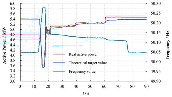
Figure 5.
Simulation of frequency increase caused by the disturbance.
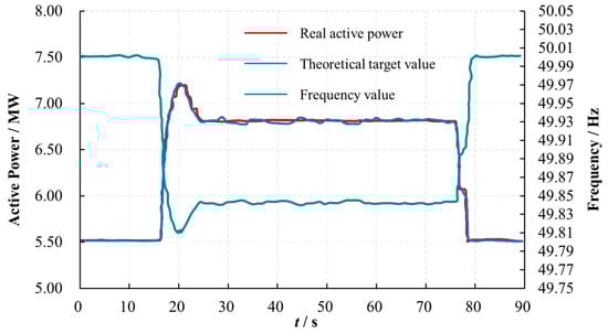
Figure 6.
Simulation of frequency decrease caused by the disturbance.
In Figure 5, a frequency increase to 50.25 Hz triggered a rapid reduction in active power from 5.9 MW to 3.5 MW, aligning closely with the theoretical target trajectory. The system achieved near-instantaneous tracking, with a response lag time of <0.1 s and negligible deviation. In Figure 6, a frequency decrease to 49.75 Hz prompted an active power increase from 7.25 MW to 5.5 MW, demonstrating symmetrical adaptability. The real power consistently matched the theoretical values within 0.2 s, underscoring the system’s bidirectional responsiveness. This precise tracking of complex frequency profiles (Figure 5 and Figure 6) signifies the system’s capability to enable PV stations to act as reliable grid-supportive assets, contributing to damping frequency oscillations under realistic conditions.
These results confirm that the proposed control strategy enables precise and rapid power adjustments during both over- and under-frequency events, effectively stabilizing grid frequency while maintaining a minimal tracking error. The inverse correlation between active power and frequency, power reduction during frequency rise, and vice versa, aligns with grid stability requirements, validating the system’s suitability for real-world transient scenarios.
5.3. Dynamic Reactive Power Response Test
To evaluate the dynamic reactive power response capability, simulation tests were conducted for two critical scenarios: a sudden voltage rise and a sudden voltage drop at the grid-connection point. Figure 7 and Figure 8 show the reactive power dynamic response curves obtained from these simulations under these two cases, i.e., voltage rise and drop, respectively. Among them, the voltage rises to 513 V and recovers after 27.12 ms, and the maximum voltage drops to 508 V and recovers after 23.15 ms, the voltage overshoot is less than 0.5% UN, and the stability regulation accuracy is less than 0.2% UN, where UN is the positive sequence voltage of the grid point.
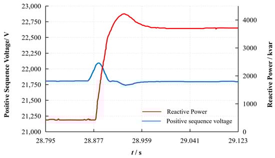
Figure 7.
Reactive dynamic response curve during voltage rise.
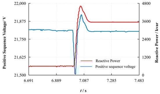
Figure 8.
Reactive dynamic response curve during voltage drop.
5.4. Analysis of Field Operation Data
The performance of the proposed system was also validated using actual online operational data obtained after its commissioning in a real-world PV station. This allows for an assessment of the system’s behavior under continuous, real-world conditions, as opposed to the specific, controlled disturbance scenarios investigated via simulation. Figure 9 shows the actual operating curve for a single day. From Figure 9, it can be seen that the voltage at the grid-connected point strictly follows the target voltage curve of the grid, with an accuracy of less than 0.2% UN, and there is no voltage overrun during the working time.
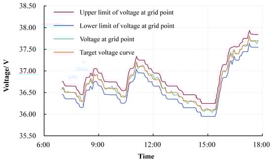
Figure 9.
Simulation of frequency decrease caused by the disturbance.
The transient stability control strategy and architectural design for the PV system, considering rapid power control technology in this paper, can meet the actual requirements in the field test.
Among them, the maximum response time of the primary frequency step disturbance test is 0.15 s, the maximum regulation time is 1.73 s, and the maximum control deviation is 0.34%. The qualification rate of the simulated actual network frequency minimum output response is 73.71%, the qualification rate of the minimum output integral power is 96.53%, and the minimum qualification rate is 85.12%. The dynamic reactive power response time is 27.12 ms and 23.15 ms for the two cases of absorbing and emitting reactive power, respectively. The maximum regulation accuracy of reactive power control capability is 1.91%, and the maximum response time is 24.36 ms.
6. Conclusions
This paper proposes a new type of rapid power control strategy for photovoltaic power stations, combining an efficient communication architecture with an improved rapid response mechanism, achieving an innovative “adjusting instead of cutting” active power regulation mode. Unlike conventional methods, this system ensures grid stability by dynamically balancing power output during transient disturbances, achieving sub-second response times and minimal tracking errors. Experimental validation demonstrates robust adaptability to both over- and under-frequency scenarios, with real-time power adjustments closely aligning theoretical and operational trajectories and effectively addressing the challenge of achieving rapid power control in photovoltaic stations and isolated grid operation, offering a scalable solution for enhancing power system resilience under dynamic grid conditions. However, it is important to acknowledge certain practical limitations and considerations for the proposed distributed communication framework. The reliance on high-speed, low-latency local communication networks is crucial for achieving the reported millisecond-timescale responses. The deployment or retrofitting of such infrastructure could present cost and logistical challenges in some existing or large-scale PV stations.
Author Contributions
Conceptualization, M.W. and M.C.; methodology, M.W. and Y.Z. (Yayao Zhang); software, M.W. and M.C.; validation, M.W. and Y.Z. (Yuanfu Zhu); writing—original draft preparation, M.W.; writing—review and editing, M.W. and J.Y.; resources, formal analysis, Y.Z. (Yihua Zhu). All authors have read and agreed to the published version of the manuscript.
Funding
This work was supported by the Innovation Project of China Southern Power Grid—Research on Transient Stability and Control Technology of Power Systems with High Penetration of Renewables and Power Electronics (YNKJXM20222169).
Data Availability Statement
The data that support the findings of this study are available from the corresponding author upon reasonable request.
Conflicts of Interest
Authors Mingkang Wu, Jiawei Yu and Yihua Zhu were employed by the State Key Laboratory of HVDC (Electric Power Research Institute, China Southern Power Grid). Authors Min Cheng and Yuanfu Zhu were employed by the Yunnan Electric Power Dispatching and Control Center, Yunnan Power Grid Co., Ltd. The remaining authors declare that the research was conducted in the absence of any commercial or financial relationships that could be construed as a potential conflict of interest.
References
- Zhang, Y.; Zang, C.; Xiao, J.; Zhou, Z.; Li, X. Key technologies and equipment of new power system based on renewable energy. J. Glob. Energy Interconnect. 2022, 5, 215–220. [Google Scholar]
- Li, Y.; Zhang, T.; Zhang, H.; Cui, P.; Fu, Z.; Gao, Z.; Geng, Q.; Liu, Z.; Zhu, Q.; Li, H.; et al. Efficient and comprehensive photovoltaic/photothermal utilization technologies for solar energy. Power Gener. Technol. 2022, 43, 373. [Google Scholar]
- Zhang, J.; Li, J.; Tang, Z.; Chen, Q.; Hao, L.; Li, Y.; Xu, Z. Local measurement based unbalanced active power estimation and supplementary power modulation for power systems with high proportions of renewable energy. J. Electr. Power Sci. Technol. 2022, 37, 50–60. [Google Scholar]
- Zhong, C.; Gui, Q.; Jiang, Q. Data-driven distributed voltage control for high-penetration renewable power clusters without complete model. J. Glob. Energy Interconnect. 2022, 5, 254–263. [Google Scholar]
- Ding, J.; Qammar, A.; Zhang, Z.; Karim, A.; Ning, H. Cyber threats to smart grids: Review, taxonomy, potential solutions, and future directions. Energies 2022, 15, 6799. [Google Scholar] [CrossRef]
- Kumar, N.; Hussain, I.; Singh, B.; Panigrahi, B.K. Peak power detection of PS solar PV panel by using WPSCO. IET Renew. Power Gener. 2017, 11, 480–489. [Google Scholar] [CrossRef]
- Zhu, Y.; Shi, X.; Dan, Y.; Li, P.; Liu, W.; Wei, D.; Fu, C. Application of PSO algorithm in global MPPT for PV array. Proc. CSEE 2012, 32, 42–48. [Google Scholar]
- Wu, Z.; Yu, D. Application of improved bat algorithm for solar PV maximum power point tracking under partially shaded condition. Appl. Soft Comput. 2018, 62, 101–109. [Google Scholar] [CrossRef]
- Yang, B.; Zhong, L.; Zhang, X.; Shu, H.; Yu, T.; Li, H.; Jiang, L.; Sun, L. Novel bio-inspired memetic salp swarm algorithm and application to MPPT for PV systems considering partial shading condition. J. Clean. Prod. 2019, 215, 1203–1222. [Google Scholar]
- Shang, L.; Zhu, W. Photovoltaic system global maximum power point tracking method based on the global learning adaptive bacteria foraging algorithm. Trans. China Electrotech. Soc. 2019, 34, 2606–2614. [Google Scholar]
- Priyadarshi, N.; Azam, F.; Sharma, A.K.; Vardia, M. An Adaptive Neuro-Fuzzy Inference System-Based Intelligent Grid-Connected Photovoltaic Power Generation. In Advances in Computational Intelligence; Proceedings of Second International Conference on Computational Intelligence 2018; Springer: Singapore, 2020; pp. 3–14. [Google Scholar]
- Kulaksız, A.A.; Akkaya, R. A genetic algorithm optimized ANN-based MPPT algorithm for a stand-alone PV system with induction motor drive. Sol. Energy 2012, 86, 2366–2375. [Google Scholar]
- Cai, M.; Sun, G.H.; Wu, X.C.; Liu, C.; Chen, S. Analysis and application of AC fault criterion in power system stability control. Autom. Electr. Power Syst. 2007, 31, 46–51. [Google Scholar]
- Tafti, H.D.; Konstantinou, G.; Townsend, C.D.; Farivar, G.G.; Sangwongwanich, A.; Yang, Y. Extended functionalities of photovoltaic systems with flexible power point tracking: Recent advances. IEEE Trans. Power Electron. 2020, 35, 9342–9356. [Google Scholar] [CrossRef]
- Shi, Y.; Don, Z. Adaptive tracking control algorithm for flexible power point of photovoltaic system considering dynamic environment. Proc. Chongqing Univ. 2021, 44, 59–75. [Google Scholar]
- Zhong, C.; Zhou, Y.; Zhang, X.P.; Yan, G. Flexible power-point-tracking-based frequency regulation strategy for PV system. IET Renew. Power Gener. 2020, 14, 1797–1807. [Google Scholar] [CrossRef]
- Chen, Y.; Luo, A.; Zhou, J.; Bai, L.; Tu, C. A rapid reactive power control method for parallel inverters using resistive-capacitive output impedance. In Proceedings of the 2013 1st International Future Energy Electronics Conference (IFEEC), Tainan, Taiwan, 3–6 November 2013; pp. 98–102. [Google Scholar]
- Mohamed, N. Renewable Energy in the Age of AI: Cybersecurity Challenges and Opportunities. In Proceedings of the 2024 15th International Conference on Computing Communication and Networking Technologies (ICCCNT), Kamand, India, 24–28 June 2024; IEEE: Kamand, India, 2024; pp. 1–6. [Google Scholar]
- Sun, X.; Liu, X.; Cheng, S.; Duan, N.; Chu, Y.; Zhang, L.; Yan, B. Actual measurement and analysis of fast frequency response capability of PV-inverters in northwest power grid. Power Syst. Technol. 2017, 41, 2792–2798. [Google Scholar]
- Hoke, A.F.; Shirazi, M.; Chakraborty, S.; Muljadi, E.; Maksimovic, D. Rapid active power control of photovoltaic systems for grid frequency support. IEEE J. Emerg. Sel. Top. Power Electron. 2017, 5, 1154–1163. [Google Scholar] [CrossRef]
- Ding, M.; Wang, W.; Wang, X.; Song, Y.T.; Chen, D.Z.; Sun, M. A review on the effect of large-scale PV generation on power systems. Proc. CSEE 2014, 34, 1–14. [Google Scholar]
- Shu, Y.; Zhang, Z.; Guo, J.; Zhang, Z.L. Study on key factors and solution of renewable energy accommodation. Proc. CSEE 2017, 37, 1–8. [Google Scholar]
- Chen, W.; Ai, X.; Wu, T.; Liu, H. Influence of grid-connected photovoltaic system on power network. Electr. Power Autom. equipment 2013, 33, 26–32. [Google Scholar]
- Lei, Y.; Zhao, Z. Overview of large-scale PV integration key technologies and its impact. Power Electron. 2010, 3, 16–23. [Google Scholar]
- Wei, H.E.; Tuoxin, C.H.; Weizhe, Z.H. Active power standby photovoltaic system based on improved droop control strategy. Power Capacit. React. Power Compens. 2021, 42, 251–260. [Google Scholar]
- Chen, S.; Liang, F.; Li, Y. Research on reactive power supply optimization method in photovoltaic power station. Electrotech. Electr. 2017, 27–31. [Google Scholar]
- Liu, Y.; Zhang, H. Variable step size MPPT method based on variable scaling factor. Chin. J. Power Sources 2017, 41, 777–779. [Google Scholar]
- Cao, M.; Shao, C.; Hu, B.; Xie, K.; Li, W.; Peng, L.; Zhang, W. Reliability Assessment of Integrated Energy Systems Considering Emergency Dispatch Based on Dynamic Optimal Energy Flow. IEEE Trans. Sustain. Energy 2022, 13, 290–301. [Google Scholar] [CrossRef]
- Xu, L.; Hu, B.; Shao, C.; Xie, K.; Pan, C.; Tai, H.M.; Li, W. A fully analytical approach for the real-time dynamic reliability evaluation of composite power systems with renewable energy sources. Engineering, 2024; in press. [Google Scholar] [CrossRef]
Disclaimer/Publisher’s Note: The statements, opinions and data contained in all publications are solely those of the individual author(s) and contributor(s) and not of MDPI and/or the editor(s). MDPI and/or the editor(s) disclaim responsibility for any injury to people or property resulting from any ideas, methods, instructions or products referred to in the content. |
© 2025 by the authors. Licensee MDPI, Basel, Switzerland. This article is an open access article distributed under the terms and conditions of the Creative Commons Attribution (CC BY) license (https://creativecommons.org/licenses/by/4.0/).